1
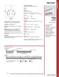
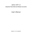
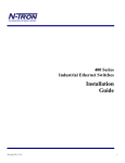
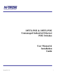
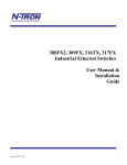
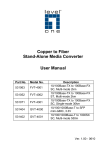
Copper to Fiber Stand-Alone Media Converter Quick Installation Guide Model No. FVT-2001 FVT-2002 FVT-2201 FVT-2401 GVT-2000 GVT-2001 Description 10/100BASE-TX to 100BASE-FX MMF SC Converter, 2km 10/100BASE-TX to 100BASE-FX MMF ST Converter, 2km 10/100BASE-TX to 100BASE-FX SMF SC Converter, 20km 10/100BASE-TX to 100BASE-FX SMF SC Converter, 40km 10/100/1000BASE-T to 1000BASE-X SFP Converter 10/100/1000BASE-T to 1000BASE-SX MMF SC Converter, 550m Ver. 1.2 - 1305 Table of Contents 1. INTRODUCTION ................................................... 1 1.1. 1.2. 2. FEATURES ............................................................ 1 PACKAGE CONTENTS ........................................... 2 HARDWARE DESCRIPTION .............................. 3 2.1. 2.2. 2.3. 2.4. FRONT PANEL ...................................................... 3 REAR PANEL ........................................................ 4 LED INDICATORS ................................................ 5 DIP-SWITCH......................................................... 7 3. CABLING ................................................................ 9 4. SPECIFICATION ................................................. 11 5. OPTIONAL SFP MODULES............................... 13 1. Introduction LevelOne media converters are Fast Ethernet 100Base-TX to 100Base-FX and 1000Base-T to 1000Base-SX/LX converters to provide the flexibility required in network integration. The TX port auto-sense connection speed, auto-negotiates half/full duplex modes and auto-selects MDIX media type. The fiber connectors come with multimode or singlemode, SC, ST or SFP connector to provide necessary connection interface and distance capabilities. LevelOne have designed 19” racks to organize media converters the smart way by providing a single power supply. With the Plug-and-play technology, the converter is easy to set-up and run. For simple, cost-effective network design, LevelOne converter series is the perfect solution to bridge the complex network infrastructure. 1.1. Features Fast Ethernet Module Comply with IEEE 802.3, 802.3u, and 802.3x standards. Convert between UTP cabling and Fiber-optic cabling. One RJ-45 connector, Auto-MDI/MDIX for UTP port. Support 10/100 Mbps Auto-negotiation for UTP port. Fiber cabling connectivity up to 40Km. Store-and-forward switching to separate two collision domains. One fiber connector (SC/ ST) for 100Base-FX. 6DIP-switches to set the operation mode Link- Lost-Forwarding function. 1 Gigabit Ethernet Module Comply with IEEE 802.3, 802.3u, and 802.3x, IEEE 802.3ab, 1000BaseT, 802.3z, 1000BaseSX/LX standards Convert between UTP cabling and Fiber-optic cabling. One RJ-45 connector, Auto-MDI/MDIX for UTP port. Support 10/100/1000 Mbps Auto-negotiation for UTP port Fiber cabling connectivity up to 80Km. Store-and-forward switching to separate two collision domains. One fiber connector (SC / SFP) for 1000Base-SX/LX DIP-switches to set the operation mode function. Link- Lost-Forwarding function. 1.2. Package Contents - Stand-alone Media Converter Power Adapter (10/100M 5V,1A; 10/100/1000M 5V,2A) User Manual Compare the contents of your converter module with the checklist above. If any item is damaged or missing, please contact your local dealer for service. 2 2. Hardware Description 2.1. Front Panel FVT-2001 / FVT-2002 / FVT-2201 / FVT-2401 GVT-2000 GVT-2001 3 (1) RJ-45 Port (2) LED Indicators 1 4 (3) Fiber/SFP Connector (4) DIP-Switch 2 3 2.2. Rear Panel 4 Power Adapter: (10/100M DC 5V, 1A; 10/100/1000M DC 5V, 2A) The rear panel contains a power socket. This power socket accepts DC 5V voltage and minimum 1A & 2A supplied current. 4 2.3. LED Indicators Fast Ethernet Module LED Status PWR On Power on FX 100 On 100Mbps Fiber Speed On 100Mbps UTP Speed OFF 10 Mbps UTP Speed TX 100 FDX FX LINK/ACT On Converter works in the full duplex mode OFF Converter works in the half duplex mode On Connection status display for fiber link. “ON” indicates that Fiber link is in correct connection. Blinks TX LINK/ACT Meaning On Blinks Active status display of fiber link “Blink” indicates packet goes through FX end. Connection status display for electric link. “ON” indicates that electric link is in correct connection. Active status display of fiber link “Blink” indicates packet goes through TX end 5 Gigabit Ethernet Module LED Status PWR On Power on 1000 On 1000Mbps UTP Speed 100 On 100Mbps UTP Speed On Converter works in the full duplex mode Off Converter works in the half duplex mode FDX Meaning LINK/ACT (UTP) Blinks Active status display of electrical interface link Blink” indicates packet goes through TP LNK/ACT (Fiber) Blinks Active status display of fiber interface link “Blink” indicates packet goes through FX 6 2.4. DIP-switch The DIP-switch is used to configure operation mode for LLF (Link Lost Forwarding) and operation mode for UTP/Fiber port. The default value of DIPswitch is OFF. Fast Ethernet Module No 1 2 3 4 5 6 Status ON OFF ON OFF ON OFF ON OFF ON OFF ON Description LFP is Enable LFP is Disable Modified cut-through switch mode is enable Store and forward switch is enable force the TX port work 10/100Mbps,full/half duplex auto-negotiation mode is enable TX is 10Mbps TX is 100Mbps TX is half duplex TX is full duplex Normally close Gigabit Ethernet Module No 1 Status ON OFF Pin 2 Pin3 ON OFF Description LFP Enable LFP Disable ON OFF Pass through Modified cut through 7 Smart pass through Store and forward Link Lost Forwarding: When LLF is enable, allow UTP link failures to be reported to the fiber side and also allow Fiber link failure to be reported to the UTP side. Therefore, A link loss forward feature is provided in both UTP and Fiber side. Pure Converter mode (Fast Ethernet Module): When pure converter mode is enabling (on), it operates with the minimum latency. The transmission flow does not wait until entire frame is ready, but instead it forwards the received data immediately after the data being received. And TP port should be forced at 100M in this application. When DIP-Switch is in Switch Converter mode (off), the converter function is same as Switch Hub. Note: Please don’t change the DIP-switch setting when UTP or fiber port is transmitting or receiving data. It may cause some data error. 8 3. Cabling Fast Ethernet Module Twisted-pair segment can be use unshielded twisted pair (UTP) or shielded twisted pair (STP) cabling. The cable must comply with the IEEE 802.3u 100Base TX standard for Category 5. The cable between the converter and the link partner (switch, hub, workstation, etc.) must be less than 100 meters (328 ft.) long. Fiber segment using multi-mode connector type must use 50 or 62.5/125 um multi-mode fiber cable. You can connect two devices up to a 2-kilometer (6,562 ft.) distance. Fiber segment using single-mode connector type must use 8/125 or 9/125 um single-mode fiber cable. You can connect two devices in the distance of 30 Kilometers in full duplex operation. For half-duplex operation, the recommended maximum distance is 412 meters (1,352 ft.) Gigabit Ethernet Module Using four twisted-pair, Category 5 cabling for RJ-45 port connection. The cable between the converter and the link partner (switch, hub, workstation, etc.) must be less than 100 meters (328 ft.) long. Fiber segment using multi-mode connector type must use 50 or 62.5/125 um multi-mode fiber cable. You can connect two devices up to 550m distances. Fiber segment using single-mode connector type must use 8/125 or 9/125 um single-mode fiber cable. You can connect two devices in the distance of 10 Kilometers in full duplex operation. For half-duplex operation, the recommended maximum distance is 412 meters (1,352 ft.) 9 Optical Fiber Module Name Wavelength Avg. Launch Avg. Power Sensitivity >-21dBm -31dBm 100Base-FX Fiber SC MM 1310 (nm) 100Base-FX Fiber ST MM 100Base-FX Fiber SC SM 20KM 100Base-FX Fiber SC SM 40KM 1000Base-SX Fiber SC MM 1310 (nm) >-21dBm -31dBm 1310 (nm) >-15dBm -34dBm 1310 (nm) >-10dBm -37dBm 850 (nm) >-10.5dBm -20dBm Module Name Max. FDX Avg. Power Fiber Loss Budget Distance 100Base-FX Fiber SC MM 10 (dBm) 2 (Km) 100Base-FX Fiber ST MM 10 (dBm) 2 (Km) 100Base-FX Fiber SC SM 19 (dBm) 20(Km) 100Base-FX Fiber SC SM 27 (dBm) 40(Km) 1000Base-SX Fiber SC MM 9.5 (dBm) 550 (m) 10 Fiber Size (um) 62.5/125 50/125 62.5/125 50/125 9/125 8/125 9/125 8/125 62.5/125 50/125 4. Specification Fast Ethernet Module Standard Connector Switch architecture IEEE802.3 10BASE-T IEEE802.3u 100BASE-TX/100BASE-FX IEEE802.3x Flow Control and Back pressure Fiber: Duplex ST/SC RJ-45 Socket: CAT-3/5 (10/100Mbps) Twisted Pair cable, Auto MDI/MDI-X, Auto-Negotiation Store and Forward Fiber Core: Fiber parameters Multi-Mode (62.5/125um, 50/125um) Single-Mode (8/125um, 9/125um) Wavelength: 1310nm(Multi-mode) 1310nm(Single-mode) Fiber Distance: Multi-Mode Fiber 2KM Single-Mode Fiber (20KM or 40KM) Transparent packet 64 to 1600 Bytes for Non-VLAN Ethernet packet UTPFiber: If UTP port link down, then converter will forced Link Fault fiber to link down. Pass through Fiber UTP: If Fiber port link down, the media converter will force UTP port to link down. DIP Switch DIP Switch 1: LFP function DIP Switch 2: Transmission Mode DIP Switch 3: Auto/Force the UTP port work mode DIP Switch 4: 10/100M for UTP port DIP Switch 5: Full/Half Duplex mode for UTP port DIP Switch 6: Normally close LED Power, UTP (100Mbps, LINK/ACT, FDX) Fiber (LINK/ACT, 100Mbps) Power DC5V / 1A Dimension 71mm x 94mm x 26mm EMI & safety CE, FCC Class A 11 Gigabit Ethernet Module Standard Connector IEEE802.3 10BASE-T IEEE802.3u 100BASE-TX/100BASE-FX IEEE 802.3ab 1000BaseT IEEE 802.3z 1000BaseSX/LX standards IEEE802.3x Flow Control and Back pressure Fiber: SC / SFP RJ-45 Socket: CAT-5 (10/100/1000Mbps or pure 1000Mbps) Twisted Pair cable, Auto MDI/MDI-X, Auto-Negotiation Switch architecture Store and Forward Fiber parameters Fiber Core: Multi-Mode (62.5/125um, 50/125um) Wavelength: 1310nm(Multi-mode) Fiber Distance: 550M (Multi-Mode Fiber) Transparent packet 64 to 9000 Bytes for Ethernet packet Power UTPFiber: If UTP port link down, then converter will forced fiber to link down. Fiber UTP: If Fiber port link down, the media converter will force UTP port to link down. DIP Switch 1: LFP function DIP Switch 2 and 3 performance 4 types work mode DIP Switch 2 and 3 is OFF = Store and forward DIP Switch 2 is OFF, 3 is ON = Cut through mode DIP Switch 2 is ON, 3 is OFF = Smart pass through DIP Switch 2 and 3 is ON = Pass through mode Power, UTP (LINK/ACT, 100Mbps, 1000Mbps FDX) Fiber (LINK/ACT) DC5V / 2A Dimension 71mm x 94mm x 26mm Link Lost Forward DIP Switch LED EMI & safety CE, FCC Class A 12 5. Optional SFP Modules CVH-2000 supports 3.3V mini-GBIC module Model No. Description GVT-0300 1.25G MMF SFP Transceiver, 550 m, 850nm GVT-0301 1.25G SMF SFP Transceiver, 10 km, 1310nm GVT-0302 1.25G SMF SFP Transceiver, 80 km, 1550nm 13