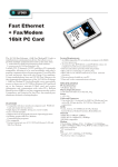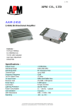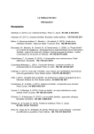
1
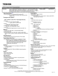
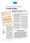
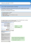
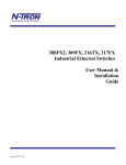
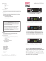
Installation Guide: MIL-S311X Series
r‡‰š‘ƒ™”—Ÿ@a••—”›ƒ‘
-
FCC Class A
UL 1950
CSA C22.2 Number 950
EN60950
CE
- EN55022 Class B
- EN55024
pR
pQ
mdiMxOmdi
pR
cƒ“ƒ†‹ƒ“@emi@n”™‹…‡
This Class A digital apparatus meets all the requirements of the Canadian Interference-Causing Equipment Regulations.
Cet appareil numerique de la classe A respecte toutes les exigences du Reglement sur le materiel brouilleur du Canada.
eš—”•‡ƒ“@n”™‹…‡
Products with the CE Marking comply with both the EMC Directive (89/336/EEC) and the Low Voltage
Directive (73/23/EEC) issued by the commission of the European Community Compliance with these directives
implies conformity to the following European Norms:
-
mdiMxOmdi
MIL-S3110
tx
MiLAN Technology makes no express or implied warranties including, but not limited to, any
implied warranty of merchantability or fitness for a particular purpose, except as expressly set
forth in this warranty. In no event shall MiLAN Technology be liable for incidental or
consequential damages, costs, or expenses arising out of or in connection with the performance
of the product delivered hereunder. MiLAN Technology will in no case cover damages arising
out of the product being used in a negligent fashion or manner.
t—ƒ†‡’ƒ—Ž˜
© 2000 MiLAN, the MiLAN logo and MiLAN Technology are either trademarks or registered
trademarks of Digi International, Inc. in the United States and/or other countries. All other
trademarks are the property of their respective holders.
pR
pQ
rx
mdiMxOmdi
pR
MIL-S3112
f‹›‡My‡ƒ—@l‹’‹™‡†@wƒ——ƒ“™Ÿ
QPOQPPbaseMtx
MIL-S3110 provides 10/100BASE-TX to 10/100BASE-TX
EN55022 (CISPR 22) - Radio Frequency Interference
EN61000-X - Electromagnetic Immunity
EN60950 (IEC950) - Product Safety
MiLAN Technology warrants to the original consumer or purchaser that each of itís products, and
all components thereof, will be free from defects in material and/or workmanship for a period of
five years from the original factory shipment date. Any warranty hereunder is extended to the
original consumer or purchaser and is not assignable.
pQ
lnk act fdx spd
QPOQPPbaseMtx
QPPbaseMfx@HstI
mmf@Rk’
pQ
lnk act fdx spd
QPOQPPbaseMtx
MIL-S3112 provides 10/100BASE-TX to 100BASE-FX, MMF with ST connector.
tx
pR
pQ
rx
mdiMxOmdi
pR
MIL-S3113
QPPbaseMfx@HscI
mmf@Rk’
pQ
lnk act fdx spd
QPOQPPbaseMtx
MIL-S3113 provides 10/100BASE-TX to 100BASE-FX, MMF with SC connector.
MIL-S3113-15 provides 10/100BASE-TX to 100BASE-FX, SMF with SC connector.
MIL-S3113-40 provides 10/100BASE-TX to 100BASE-FX, SMF with SC connector.
MIL-S3113-60 provides 10/100BASE-TX to 100BASE-FX, SMF with SC connector.
MIL-S3113-100 provides 10/100BASE-TX to 100BASE-FX, SMF with SC connector.
t”@c”“™ƒ…™@m‹lan@t‡…Š“”‘”‰Ÿ
For prompt response when calling for service information, have the following information ready:
- Product serial number and revision
- Date of purchase
- Vendor or place of purchase
MIL-S3114
QPPbaseMfx@HmtMrjI
mmf@Rk’
pQ
lnk act fdx spd
QPOQPPbaseMtx
MIL-S3114 provides 10/100BASE-TX to 100BASE-FX, MMF with MT-RJ connector.
MIL-S3114-15 provides 10/100BASE-TX to 100BASE-FX, SMF with MT-RJ connector.
MiLAN Technology
1299 Orleans Drive
Sunnyvale, CA 94089-1138
United States of America
Telephone: +1.408.744.2775
Fax: +1.408.744.2793
http://www.milan.com
[email protected]
© Copyright 2000 MiLAN Technology
mdiMxOmdi
pR
You can reach MiLAN Technology technical support at:
E-mail: [email protected]
Telephone: +1.408.744.2751
Fax: +1.408.744.2771
pQ
pR
P/N: 90000221 Rev. B
The MIL-S311X series are stand-alone Ethernet media and rate
converters. The series provides packet switch functions between 10Mbps
and 100Mbps using store and forward architecture at full wire speed.
They also support auto-negotiation on a per-port basis; more than 8k
MAC addresses; Packet buffer memory of 2Mbytes, backpressure in halfduplex mode and VLAN Tag packet size feature.
To maximize the fiber cable distance, use one meter of CAT 5 UTP cable
when connecting directly to a node (subject to fiber budget of 16dBm and
collision domain restrictions). In full-duplex environments, use up to
100m of CAT 5 UTP and:
4 2Km of multi-mode optical fiber for MIL-S3412, S3413, S3414
4 15Km of single-mode optical fiber for MIL-S3413-15, S3414-15
4 40Km of single-mode optical fiber for MIL-S3413-40
4 70Km of single-mode optical fiber for MIL-S3413-70
4 100Km of single-mode optical fiber for MIL-S3413-100
Multi-mode fiber (2Km)
4 1300nm wavelength
4 62.5/125 micron diameter
4 Launch power: -19dBm minimum
4 -31dBm receive sensitivity
Single-mode fiber (15Km)
4 1300nm wavelength
4 9/125 micron diameter
4 Launch power: -15dBm
4 -31dBm receive sensitivity
Single-mode fiber (40Km)
4 1300nm wavelength
4 9/125 micron diameter
4 Launch power: -4dBm minimum
4 -34dBm receive sensitivity
Single-mode fiber (60Km)
4 1550nm wavelength
4 9/125 micron diameter
4 Launch power: 0dBm minimum
4 -37dBm receive sensitivity
In s ta lla tio n
1. Make any configuration changes to the module DIP switch settings.
2. Remove cover plate from MCS chassis.
3. Slide module into a slot through the card guides.
4. Firmly seat module into card-edge connector.
5. Secure module with thumbscrews located on module faceplate.
6. Plug in network connections.
Note: There is no need to power off the Media Conversion System.
Dia g n o s tic LEDs a n d Co n d itio n s In d ica te d
There are four LEDs for both UTP and fiber ports:
4 D = Duplex; On indicates Full Duplex.
4 A = Activity; On indicates receiving packets at port.
4 S = Speed; On indicates rate is 100 Mbs.
4 L = LINK; On indicates an active connection at port.
1
2
3
4
5
6
7
Single-mode fiber (100Km)
4 1550nm wavelength
4 9/125 micron diameter
4 Launch power: 1.8dBm minimum
4 -37dBm receive sensitivity
7- pin DIP Switch
MDI-X/MDI
Switch
MDI-X/MDI
Switch
M DI-X / M DI S w itch (Fig u r e 1 )
LEDs
The MDI-X/MDI switch allows for quick configuration of the
100BASE-TX port. Cables used when the switch is in the MDI-X
position (the "left" position:
4 For a hub/repeater, use a swap cable (pins are
connected 1 to 3, 2 to 6, 3 to 1, and 6 to 2).
4 For a workstation/PC, use a straight-through cable
(pins are connected 1 to 1, 2 to 2, 3 to 3, and 6 to 6).
Cables used when the switch is in the MDI position (the"right"
position):
4 For a hub/repeater, use a straight-through cable (pins
are connected 1 to 1, 2 to 2, 3 to 3, and 6 to 6).
4 For a workstation/PC, use a swap cable (pins are
connected 1 to 3, 2 to 6, 3 to 1, and 6 to 2).
MDI-X
p‹“@Q]rxK
p‹“@R]rxM
p‹“@S]txK
p‹“@V]txM
3 4
1 2
Fig u r e 2 . In s id e o f th e M IL-S 3 4 1 0
Dip S w itch Fe a tu r e s (Fig u r e 2 )
Speed and Half/Full Duplex or Auto Negotiation may be manually
selected using the seven-position DIP switch.
All switches must be in the up position to utilize SNMP feature selection.
Fiber ports operate at 100Mbs only.
Port 1 is on the left. Port 2 is on the right.
f‹‰š—‡@QN@rjMTU@p‹“”š™˜
Switch 2
Auto-Negotiation
Switch 3
Speed
100Mbs Port 1
Up Position
Switch 1
Auto-Negotiation
Enable Port 1
Down Position
Disable Port 1
Enable Port 2
Disable Port 2
Switch 4
Speed
Switch 5
Duplex
Switch 6
Duplex
Switch 7
Packet size
100Mbs Port 2
10Mbs Port 2
FDX Port 1
HDX Port 1
FDX Port 2
HDX Port 2
1518 Bytes
1522 Bytes
5 6 7 8
MDI
@@@@@@@@@@@@@@@@@@@p‹“@Q]txK
p‹“@R]txM
p‹“@S]rxK
p‹“@V]rxM
RJ -45
Connector
RJ -45
Connector
Up Position
Down Position
10Mbs Port 1