1
X-1000VL
X-2000V / X-2000V Zip
X-2300E / X-2300ZE
X-3200 / X-3200Z
X-3200E / X-3200ZE
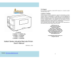
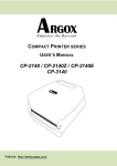
Xellent Series Industrial Barcode Printer
User’s Manual
Argox website: http://www.argox.com
I
Table of Contents
1. Getting Started
5
Unpacking
Connecting the Power Cord
Internal Parts and Features
Loading Ribbon
Switching Ribbon Wound Ink-side in or Ink-side out
Loading Media
Standard Mode Loading Media
Peel Off Mode Loading Media
Cutter Mode Loading Media
Adjust Position of Label Sensor
2. Printer Operation
5
8
10
13
17
19
20
24
28
31
32
Front Panel
LED Indicators
Buttons
LCD Display
Setting Display Language
Changing Settings from the Panel
Media Calibration
Printing a Configuration Report
Resetting to Factory Default Settings
3. Computer Connections
32
33
34
35
37
38
46
47
51
52
USB Interface Requirements
Centronics Parallel Port
Serial (RS-232) Port
Ethernet 10/100 Internal Printer Server Option
Ethernet Module Status Indicators
Communicating with the Printer
Installing a Plug and Play printer driver (for USB only)
II
52
52
53
54
54
56
56
Installing a Printer Driver (for other interfaces except USB)
62
4. Troubleshooting
69
LED and LCD Diagnosis
Media Problems
Ribbon Problems
Other Problems
Printer Status
Transmission Problems
Recovery
Printer Maintenance
Cleaning the Print Head
Cleaning Interval
Cleaning Material
Cleaning Direction
Cleaning the Roller
Cleaning the Media Compartment
5. Advanced Installation and Adjustment
Print Head Pressure
Print Head Print Line Position
Ribbon Tension Adjustment
Printing Wrinkle
Rotary Cutter and Guillotine Cutter Installation
Rotary Cutter and Guillotine Cutter Settings
Rotary Cutter with Paper Jam
Guillotine Cutter with Paper Jam
Dispenser Installation
RTC Battery Replacement
Stand-alone with Keyboard
Stand-alone with Barcode Reader
III
69
69
70
70
71
72
72
73
74
74
74
75
75
75
76
76
79
82
84
87
90
93
94
95
98
99
105
6. Technical Reference
109
General Specifications
Printer Programming Language A, PPLA
Printer Programming Language B, PPLB
Printer Programming Language Z, PPLZ
Interface Specifications
USB
PS/2
Serial Interface
Connection with Host:
Parallel (Centronics)
Ethernet Interface
Auto Polling
ASCII TABLE
IV
109
113
114
116
118
118
118
119
120
122
123
123
124
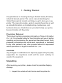
1. Getting Started
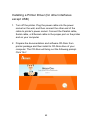
Congratulations on choosing the Argox Xellent Series (X-Series)
industrial barcode printer. This user’s manual describing the
Xellent Series printer models, will help you get to know your new
printer. The manual includes a guide to operate the printer as well
as related information on troubleshooting, maintenance, and
technical reference. Illustrations are provided to help you quickly
become familiar with the printer.
Proprietary Statement
This manual contains proprietary information of Argox Information
Co., Ltd. It is intended solely for the information and use of parties
operating and maintaining the equipment described herein. Such
proprietary information may not be used, reproduced, or disclosed
to any other parties for any other purpose without the expressed
written permission of Argox Information Co., Ltd.
CAUTION:
Any changes or modifications not expressly approved by the party
responsible for compliance could void the user's authority to
operate the equipment.
Unpacking
After receiving your printer, please check for possible shipping
damage:
1. Inspect the outside of both the box and the printer for
5
possible damage.
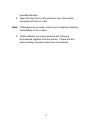
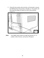
2. Open the top cover of the printer to see if the media
compartments are in order.
Note: If damage has occurred, contact your shipping company
immediately to file a claim.
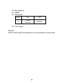
3. Check whether you have received the following
accessories together with the printer. If there are any
items missing, please contact your local dealer.
6
Printer
Quick
Guide
Power Cord
USB Cable
CD ROM
1” ID Core for
Ribbon
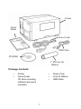
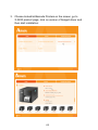
Package Contents
Printer
Quick Guide
CD Rom (including
software and user’s
manuals)
7
Power Cord
Core for Ribbon
USB Cable
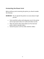
Connecting the Power Cord
Before setting up and connecting the printer you should consider
the following.
WARNING! Do not operate the printer in an area where it might
get wet.
Find a solid flat surface with adequate room for the printer
and enough space above for media and ribbon access.
Place the printer within cable distance of the host and
printer (serial or parallel cable.)
Isolate the power cord from other electrical cables.
8
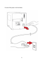
Connect the power cord as below.
9
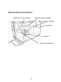
Internal Parts and Features
Ribbon Supply Spindle
Ribbon Pick-up Spindle
Media Supply Spindle
Feed Slot
Bracket
Thermal Print Head
10
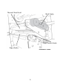
Thermal Print Head
Head Latch
Paper Sensor Guide
Paper Roller
Standard Mode
11
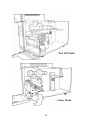
Peel Off Mode
Cutter Mode
12
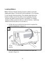
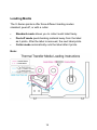
Loading Ribbon
Note: Thermal Transfer printing requires media to print with
appropriate ribbon. This section can be referred to, for X-Series
to use transfer thermal printing. The sample steps below are
based on ribbon wound ink-side in as an example.(X series
printers use ribbon wound ink-side in as default. To change
setting to ribbon would ink-side out, refer to Section - Switching
Ribbon Wound Ink-side out or Ink-side in)
1. Lift the top cover and front access door to expose the
media compartment. (Figure 1)
1
2. Turn the head latch counter-clockwise and open the
bracket. (Figure 2)
13
2
Head
Latch
Bracket
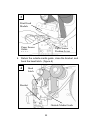
3. Unwrap the ribbon and separate the ribbon roll from the
bare core. Insert the ribbon roll onto the ribbon supply
spindle. (Figure 3)
3
Ribbon Supply
Spindle
14
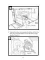
4. Lead the ribbon through the print head module. (Figure 4)
5. Attach the edge of the ribbon onto the bare core and wind
it a bit onto the core. Make sure the coating side of the
ribbon is face down.
4
Print
Head
Module
Bare Core
15
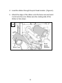
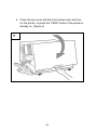
6. Insert the core onto the ribbon pick-up spindle. (Figure 5)
5
Ribbon
Ribbon
Pick-up
Pick-up
Spindle
Spindle
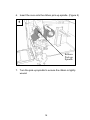
7. Turn the pick-up spindle to ensure the ribbon is tightly
wound.
16
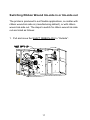
Switching Ribbon Wound Ink-side in or Ink-side out
The printer is produced to suit flexible applications, no matter with
ribbon wound ink-side in (manufacturing default), or with ribbon
wound ink-side out. The steps to switch for ribbon wound ink-side
out are listed as follows:
1. Pull and move the SHAFT RIBBON ADJ to “Outside”:
17
2. After the adjustment above, ribbon wound ink-side out can be
used. Then install the ribbon:
3. If ribbon wound ink-side in is in use, pull and move the
SHAFT RIBBON ADJ to “Inside”. Then install the ribbon:
18
Loading Media
The X-Series printers offer three different loading modes:
standard, peel-off, or with a cutter.
Standard mode allows you to collect each label freely.
Peel-off mode peels backing material away from the label
as it prints. After the label is removed, the next label prints.
Cutter mode automatically cuts the label after it prints.
Note:
19
Standard Mode Loading Media
1. Insert the media roll into the media supply spindle and
move the media guide to the inside. (Figure 1)
1
Media
Guide
Media Supply
Spindle
20
2. Turn the head latch counter-clockwise and open the
bracket. Remove the outside media guide. (Figure 2)
2
Head
Latch
Outside
Media
Guide
Bracket
3. Lead the media through the print head module and under
the paper sensor guide. (Figure 3)
21
3
Print Head
Module
Paper Sensor
Guide
Module
Paper Sensor
Position Lever
4. Return the outside media guide, close the bracket, and
hook the head latch. (Figure 4)
4
Head
Latch
Bracket
Outside Media Guide
22
5. Close the top cover and the front access door and turn
on the printer, or press the “FEED” button if the printer is
already on. (Figure 5)
5
23
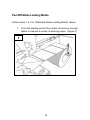
Peel Off Mode Loading Media
Follow steps 1 to 3 in “Standard Mode Loading Media” above.
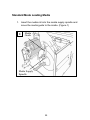
1. From the leading end of the media roll remove enough
labels to expose 6-inches of backing paper. (Figure 1)
1
Backing Paper
24
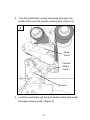
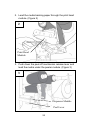
2. Lead the media backing paper through the print head
module. (Figure 2)
2
Print Head
Module
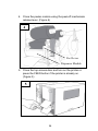
3. Push down the peel-off mechanism release lever and
lead the media under the peeler module. (Figure 3)
3
Dispenser Module
Peel Lever
25
4. Close the peeler module using the peel-off mechanism
release lever. (Figure 4)
4
Peel Lever
Dispenser Module
5. Close the top access door and turn on the printer or
press the FEED button if the printer is already on.
(Figure 5)
5
26
Notes:
1. The FEED button does not make the printer peel. To
enable Peeling function, set by the LCD panel.
2. Make sure the peeler sensor is out of the ribbon path
when installed.
27
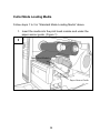
Cutter Mode Loading Media
Follow steps 1 to 3 in “Standard Mode Loading Media” above.
1. Insert the media into the print head module and under the
paper sensor guide. (Figure 1)
1
Print Head Module
Paper Sensor Guide
28
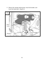
2. Return the outside media guide, close the bracket, and
hook the head latch. (Figure 2)
2
Head
Latch
Outside Media
Guide
Bracket
29
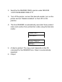
3. Close the top access door and turn on the printer or press
the FEED button if the printer is already on. The printer will
then feed the labels through the cutter automatically.
(Figure 3)
Cutter
Note:
3
The FEED button does not make the printer cut. To
enable Cutter function, set by the LCD panel
30
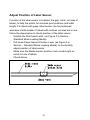
Adjust Position of Label Sensor
Function of the label sensor is to detect the gap, notch, or holes of
labels, to help the printer for accurate print positions and label
length. For labels with gaps, label sensor can be positioned
wherever media locates. If labels with notches or holes are in use,
follow the steps below to check position of the label sensor:
- Unlatch the Print head Latch. (as Figure 2 in Section –
Standard Mode Loading Media)
- Pull down Paper Sensor Position Lever (as Figure 3 in
Section – Standard Mode Loading Media), to horizontally
adjust position of label sensor.
- Make sure the Media sensor position mark locates right on
notch or hole of labels.
Check below.
31
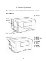
2. Printer Operation
The illustrations below describe parts and features of X-Series.
Front Panel
X-1000VL
LEDs and
Buttons
Top Access Door
Front Access Door
X-2000V
X-2000V Zip
X-2300E
X-2300ZE
X-3200
X-3200Z
X-3200E
X-3200ZE
LCD Display
32
The front panel includes:
3 LED indicators (READY, MEDIA and RIBBON)
3 buttons (FEED, PAUSE and CANCEL)
LCD display (except X-1000VL)
Top Access Door
Front Access Door
LED Indicators
There are three LED indicators on the front panel - READY,
MEDIA and RIBBON. These indicators display operation status of
the printer.
READY
On – Normal operation
Off – Error conditions including ribbon out, media
out, print tasks cancelled, printing errors, printer
paused, printer receiving data
MEDIA
On – Normal operation
Blinking – Media is used out; install new media.
Print head overheat (LCD will indicate “Print Head
Heat”; printer will resume printing automatically
later.)
RIBBON
On – thermal transfer mode with ribbon installed.
Off – direct thermal mode with no ribbon installed.
Blinking – Ribbon is used out; install new ribbon.
For the X-2000V / X-2000V Zip / X-2300E /
X-2300ZE / X-3200 / X-3200Z / X-3200E /
X-3200ZE models, modes of thermal transfer and
33
direct thermal can be set via the printer panel.
For the X-1000VL model, set via Printer Utility,
Windows driver or printer commands.
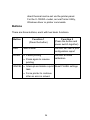
Buttons
There are three buttons, each with two basic functions.
Button
FEED
PAUSE
Function 1
(Press the button)
Feed a label
Function 2
(Press the button and
power switch together)
Perform self test & print
configuration report
Pause printing
Press again to resume
printing
Perform a media
calibration
CANCEL Interrupt and delete a print Reset FLASH settings
task
Force printer to continue
after an error is solved.
34
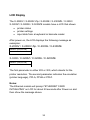
LCD Display
The X-2000V / X-2000V Zip / X-2300E / X-2300ZE / X-3200 /
X-3200Z / X-3200E / X-3200ZE models have a LCD that shows:
printer status
printer settings
input data from a keyboard or barcode reader
After power-on, the LCD displays the following message as
examples:
X-2000V / X-2000V Zip / X-2300E / X-2300ZE
READY (203,PPLB)
X-3200 / X-3200Z / X-3200E / X-3200ZE
READY (300,PPLB)
The first parameter is either 203 or 300, which stands for the
printer resolution. The second parameter indicates the emulation
(printer language), PPLA, PPLB or PPLZ.
Notes:
The Ethernet models will prompt “ETHERNET CARD
INITIALIZING” on LCD for about 20 seconds after Power-on and
then show the message above.
35
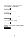
If a keyboard is plugged in, the LCD display will indicate:
X-2000V / X-2000V Zip / X-2300E / X-2300ZE
READY (203,PPLB)
<ESC> FOR KEYBD
X-3200 / X-3200Z / X-3200E / X-3200ZE
READY (300,PPLB)
<ESC> FOR KEYBD
If a barcode reader is connected, the LCD display will indicate:
X-2000V / X-2000V Zip / X-2300E / X-2300ZE
READY (203,PPLB)
WITH B.C. READER
X-3200 / X-3200Z / X-3200E / X-3200ZE
READY (300,PPLB)
WITH B.C. READER
If an abnormal condition occurs, the LCD display will indicate.
For example:
RIBBON OUT
36
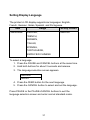
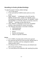
Setting Display Language
The printer’s LCD display supports six languages: English,
French, German, Italian, Spanish, and Portuguese.
Item
LANGUAGE
Range
ENGLISH,
Factory Default
ENGLISH
FRENCH,
GERMAN,
ITALIAN,
SPANISH,
PORTUGUESE,
SIMPLIFIED CHINESE
To select a language:
1. Press the PAUSE and CANCEL buttons at the same time.
2. Hold both buttons for about 3 seconds and release.
3. The language selection screen appears.
LANGUAGE
ENGLISH
4. Press the FEED button for the next language.
5. Press the CANCEL button to select and set the language.
Press PAUSE or the PAUSE+CANCEL buttons to exit the
language selection screen and enter normal standard mode.
37
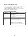
Changing Settings from the Panel
You may change settings using the buttons on the front panel of
the X-2000V, X-2000V Zip, X-2300E, X-2300ZE, X-3200,
X-3200Z, X-3200E, and X-3200ZE printer models, in addition to
changing settings via software commands.
Change settings via buttons on panel:
Buttons
PAUSE+CANCEL
Function
Press to enter setting mode. (Don’t press
over 1 second)
Press again to exit setting mode and return
to normal mode.
FEED
Press to show next parameter.
PAUSE
Press to show next setting item.
CANCEL
Selects and saves a parameter to
permanent FLASH memory. Unless
changed via panel or command the
parameter is saved even if you restart the
printer.
Note: Do not change settings during printing or sending printing
data.
38
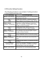
LCD Function Setting Procedure
The following procedure is an example of setting procedure
to direct thermal printing mode:
LCD indicating
READY (203,PPLB)
LCD setting steps
After printer power in on, LCD will indicate
as shown at the left.
Step 1
Press both PAUSE + CANCEL buttons.
Then release the buttons to enter settings.
LCD will then prompt LCD function
PRINT MODE
selections; default settings include the “*”
THERM. TRANSFER* sign. For example, the first option of print
modes is thermal transfer.
Keep press FEED button until LCD
Step 2
prompts the function setting needed.
PRINT MODE
For example, the second option of print
DIRECT THERMAL
modes is direct thermal.
Step 3
PRINT MODE
DIRECT THERMAL *
Step 4
Back to standard
printing mode
READY (203,PPLB)
Press CANCEL button to store the setting.
The option selected will now include the “*”
sign.
Press PAUSE button to continue the other
settings.
After LCD function settings are completed,
press both PAUSE + CANCEL and then
release them to exit from settings.
Now printer is in normal printing mode.
39
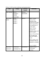
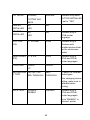
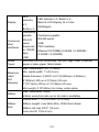
Printer LCD function settings and parameters:
Item
Range
PRINT MODE DIRECT
THERMAL/
Factory
Default
Remarks
THERM.
TRANSFER
THERM.
TRANSFER
AUTO-CAL.
MODE
MODE 1
MODE 1
MODE 2
MODE 3
MODE 4
Mode 1: Printer
performs Auto
Calibration after
printing the first label,
if label height differs
from parameters in
printer's flash.
Mode 2: Printer
performs Auto
calibration when print
head is closed.
Mode 3: Printer finds
the first label gap
when print head is
closed.
Mode 4: Mode 1/2/3
all disabled. Manual
calibration is needed.
Not for X-2000V.
CONTROL
STANDARD
CODE SET
ALTERNATIVE 1
STANDARD
40
Available only in
PPLA printer
language.
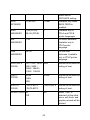
ALTERNATIVE 2
ALTERNATIVE 3
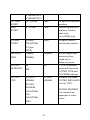
CUT PEEL
OFFSET
-15 ~ 50 mm
0 mm
To adjust cut and peel
positions.
PRINT
OFFSET
-8 ~ 15 mm
0 mm
Controls vertical print
positions. Positive
value only.
For X-2000V only.
TPH VER
OFFSET
-9~9 mm
0 mm
To adjust offset of
vertical print position.
DISABLE
Will not reprint after
recovering from
media-out or
ribbon-out errors.
NO
If “YES: is selected,
printer will then enter
CUTTER TYPE and
CUT MODE settings.
Available only when
CUTTER INSTALLED
is set to “YES”.
(PPLA/PPLB)
-3~3 mm
(PPLZ)
RECOVER
ENABLE,
PRINT
DISABLE
CUTTER
INSTALLED
NO
CUTTER
TYPE
ROTARY-
ROTARY-
NORMAL
NORMAL
YES
ROTARYREVERSE
ROTARY-REVERSE
is to recover from
paper jam in cutter
mode.
GUILLOTINEFULL
GUILLOTINEPART
41
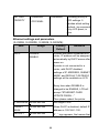
CUT MODE
NORMAL
NORMAL
CUTTER W/O
BACK
PEELER
INSTALLED
NO
READER
INSTALLED
NO
WIN. CON.
LEN.
0 ~ 254 mm
Available only when
CUTTER INSTALLED
is set to “YES”.
NO
YES
NO
Available only in
PPLB printer
language.
0 mm
Available only in
Windows with
bundled printer driver
and for continuous
media.
BASE SPEED 0 ~ 4 IPS
(IPS)
0 IPS
Available only in
PPLA and PPLB
printer languages.
COUNTING
DOWN
YES
DOWN
UP
MEDIASENSE REFLECTIVE
R TYPE
SEE-THROUGH
SEETHROUGH
To select for different
media types.
After changing sensor
setting, make sure to
calibrate before
printing.
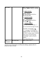
BACK FEED
DISABLE
ENABLE
DISABLE
Available only in
PPLA and PPLB
printer languages.
Once “ENABLE” is
selected, printer
42
enters BACK
DISTANCE setting.
BACK
DISTANCE
10~40 mm
21 mm
Available only when
BACK FEED is
enabled.
BASE
DARKNESS
0~99 (PPLA)
0
Available only in
PPLA and PPLB
printer languages.
ABS.
DARKNESS
0~30
0
To select darkness.
Available only in
PPLZ printer
language.
TRIM.
-30~30
0
To fine-tune
darkness. Available
only in PPLZ printer
language.
-28~28 (PPLB)
DARKNESS
BAUD RATE
(RS232)
600 / 1200 / 2400/ 9600
4800 / 9600 /
19200 / 38400 /
57600 / 115200
Should be as same as
setting of host.
PARITY
(RS232)
NONE
NONE
Should be as same as
setting of host.
8 DATA BITS
Should be as same as
setting of host.
NO
When “YES” is
selected, all the label
forms, soft fonts, and
graphics stored will be
deleted.
EVEN
ODD
LENGTH
(RS232)
8 DATA BITS
7 DATA BITS
CLEAR FLASH NO
YES
43
SETTING
PRIORITY
COMMAND/
COMMAND
LCD PANEL
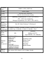
Ethernet settings and parameters
(X-2300E. X-2300ZE. X-3200E. X-3200ZE):
Item
Range
Factory
Default
DHCP
DISABLE
Choosing priority of
LCD settings. It
decides which setting
method - by command
or by LCD panel, is
prior.
Remarks
If printer has been connected to a
router, IP address will be assigned
automatically by DHCP server after
power on.
ENABLE
If printer is not connected to a
router, with DHCP disabled,
settings of IP ADDRESS, SUBNET
MASK, and DEFAULT GATEWAY
settings will be available on LCD.
Every time when DISABLE is
changed to be ENABLE, LCD will
prompt “ETHERNET CARD
UPDATE FINISH…”
IP ADDRESS xxx.xxx.xxx.xxx
Then please reboot the printer.
xxx range:0~255
SUBNET
MASK
xxx.xxx.xxx.xxx
When DHCP is disabled, default IP
address is 192.168.1.100.
DEFAULT
xxx.xxx.xxx.xxx
If “_” sign appears, that means that
44
DHCP setting is disabled. On the
contrary, DHCP setting is enabled.
GATEWAY
1. FEED/CONFIG. :
change contents.
(ex. from 000.000.000.000 to
255.255.255.255)
2. PAUSE/CALIBR. :
shift “_”sign position.
(ex. from 255.255.255.255 to
255.255.255.255)
3. CANCEL/RESET.:
Select next function setting. (“_”
sign must at the third digit of each
parameter, for example, xxx).
4. To change IP ADDRESS or
SUBNET MASK, enter DEFAULT
GATEWAY setting, press CANCEL
button once; LCD will prompt
“ETHERNET CARD UPDATE
FINISH…”
Then reboot the printer.
MAC
ADDRESS
yyyy-yyyy-yyyy
(yyyy = 0000~FFFF)
To have more information on Ethernet settings, please refer to
Ethernet User’s Guide.
45
Media Calibration
After the media is loaded, please perform media calibration to
calibrate the label sensor in advance.
1. Turn off the printer
2. Press and hold the PAUSE button and turn on the power.
3. When “CALIBRATION …” is displayed on the LCD, and
both READY and MEDIA indicators blink, release the
PAUSE button.
(The Ethernet models will first prompt “ETHERNET CARD
INITIALIZING” on LCD after Power-on and then show the
“CALIBRATION …” message as described above.)
4. The printer feeds 12-inches of blank labels.
5. When “READY” is displayed, the READY and MEDIA
indicators stop blinking but remain illuminated.
Note:
For X-1000VL, the steps about LCD can be ignored.
Important!
1. It’s suggested to perform media calibration after changing
media types.
2. Before calibration, be sure media and ribbon (for thermal
transfer printing) have been loaded correctly. The label sensor
needs to locate properly to index labels’ gaps/ notches/ holes.
3. After media calibration is finished, printer stores settings into its
flash. Without media calibration, printer may detect labels with
less accuracy, especially for small labels less than 1.5” high.
46
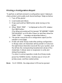
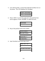
Printing a Configuration Report
To perform a self-test and print a configuration report, helping to
check printer’s print quality and internal settings. Steps as below:
1. Turn off the printer.
2. Load media and ribbon.
3. Press and hold the FEED button while turning on the
power.
4. When “SELF-TEST …” is displayed on the LCD, release
the FEED button.
(The Ethernet models will first prompt “ETHERNET CARD
INITIALIZING” on LCD after Power-on and then show the
“SELF-TEST …” message as described above.)
5. The printer now prints out a configuration report.(as the
sample in next page)
6. Printer will enter Dump mode after printing configuration.
In Dump mode, all characters will be printed in 2 columns:
the right shows characters received from your system, and
the left are the corresponding hexadecimal values of the
characters. It allows users or engineers to verify and
debug the program.
To return to normal operation mode from Dump mode,
press the CANCEL button. Another way is to turn off
printer power, and then restart printer.
Note:
For X-1000VL, the steps about LCD can be ignored.
47
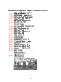
Sample of Configuration Report – based on X-2300E:
48
1.
2.
3.
4.
5.
6.
7.
8.
9.
10.
11.
12.
13.
14.
15.
16.
17.
18.
19.
20.
21.
22.
23.
24.
25.
26.
27.
28.
29.
30.
31.
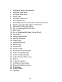
Firmware Version Information
Standard RAM Size
Available RAM Size
Flash Type
Available Flash Size
Font Symbol Set
Print Mode (Thermal Transfer or Direct Thermal)
Sensor type (See-Through or Reflective)
Label-less Calibration Value
No. of downloaded Soft Fonts
RTC Time
No. of downloaded Argox Format Fonts
Cut Count
Label Length Meter
RS232 Protocols
Check Sum
Speed/Darkness
Media Type
Print Width
Label Length
Backfeed Disable/Enable
Cutter Disable/Enable
Peeler Disable/Enable
Cutter/Peeler Offset value
R(X,Y)
H. position adjust
Calibration Type Mode
Ethernet Module Version
IP Address
Subnet Mask
Gateway
49
32. Mac Address
33. SNMP
34. DIP switch
Switch
ON
OFF
2
Direct
Thermal
Default
35. Font Image
Remark:
What continue after the parameters are test patterns of print head.
50
Resetting to Factory Default Settings
To reset the printer to factory default settings:
1. Turn off the printer.
2. Press and hold the CANCEL button and turn on the
printer.
3. When “RESET …” is displayed on the LCD and the
READY indicator blinks, release the CANCEL button.
(The Ethernet models will first prompt “ETHERNET CARD
INITIALIZING” on LCD after Power-on and then show the
“RESET …” message as described above.)
4. When “READY” is displayed on the LCD, the READY
indicator stops blinking but remains illuminated.
5. The following information is now back to defaults:
Label parameters
Heat (Darkness)
Speed
Symbol set (language)
Others for specific emulation
Notes:
1. For X-1000VL, the steps about LCD can be ignored.
2. Be cautioned that this will reset all printer settings back to
defaults; if possible, print the configuration label in
advance before reset.
3. All settings stored in FLASH memory are retained even
after turning off the printer.
4. You must perform the calibration after resetting the printer.
51
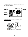
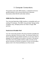
3. Computer Connections
This printer comes with USB interface, a standard Centronics
parallel interface, and a nine-pin Electronics Industries
Association (EIA) RS-232 serial data interface.
USB Interface Requirements
The Universal Serial Bus (USB) interface is compatible with your
existing PC hardware. The USB’s “plug and play” design makes
installation easy. Multiple printers can share a single USB
port/hub.
Centronics Parallel Port
You can connect the printer to the host computer’s parallel port
using any standard Centronics cable. The required cable must
have a standard 36-pin parallel connector on one end, which is
plugged into the parallel port located on the back of the printer.
The other end of the parallel interface cable connects to the
printer connector at the host computer. For pin-out information,
please refer to the Technical Reference in this manual.
52
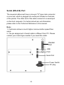
Serial (RS-232) Port
The required cable must have a nine-pin "D" type male connector
on one end, which is plugged into serial port located on the back
of the printer. The other end of the cable connects to a serial port
on the host computer. For technical and pin-out information,
please refer to the Technical Reference in this manual.
Note:
1. Centronics allows a much higher communication speed than
serial.
2. The pin assignment of serial cable is different from PC. Please
contact your local Argox reseller if you need this cable.
Parallel
Port
USB
PS/2
Serial Port
Power Switch
AC plug
53
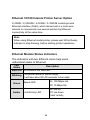
Ethernet 10/100 Internal Printer Server Option
X-2300E / X-2300ZE / X-3200E / X-3200ZE models provide
Ethernet interface (RJ45), which allows host in a local area
network to conveniently use several printers by Ethernet
connectivity at the same time.
Note:
When using Ethernet model printer, please wait till the Ready
Indicator to stop blinking, before starting printer operations.
Ethernet Module Status Indicators
The indicators with two different colors help users
understand status of Ethernet:
LED
Description
Status
Both Off No Ethernet link detected.
Blinking
Green
Amber
The printer waits for printer ready.
It will take about 20~30 seconds to be ready.
On: 100 Mbps link
Speed LED
Off: 10 Mbps link
On: link up
Off: link down
Flash: activity
Link/Activity LED
54
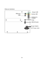
Ethernet indication:
Green LED
Ethernet
Amber LED
USB
Centronics
Parallel
PS/2
RS232 Serial
Power Switch
AC Power Jack
55
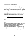
Communicating with the Printer
The bundled printer driver can be applied to all applications under
Windows XP/ Vista/ Windows 7/ Windows 8, supporting 32-bit/
64-bit operation systems. With this driver you can operate any
popular Windows software applications including Argox Bartender
UL label editing software or MS Word, etc., to print to this printer.
The following installation steps are based on X-3200 as an
example. The screens included for these steps are taken from
Windows XP; steps in other versions of operation systems are
similar. Drivers can be installed via the CD-Rom included in
printer package; or it can be downloaded from Argox website >>
Technical Support >> Download Center >> select product model
to access: http://www.argox.com/content.php?sno=0000033
Installing a Plug and Play printer driver (for USB
only)
Note:
We strongly recommend that you use the Seagull Driver Wizard
instead of the Microsoft Windows Add Printer Wizard when
installing and updating your Drivers by Seagull.
(Even though the "Add Printer Wizard" is from Microsoft, it too
easily performs a number of tasks incorrectly when updating
existing drivers. It also badly handles the situation where a printer
driver is already in use by a Windows application.)
56
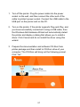
1. Turn off the printer. Plug the power cable into the power
socket on the wall, and then connect the other end of the
cable to printer's power socket. Connect the USB cable to the
USB port on the printer and on the PC.
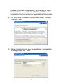
2. Turn on the printer. If the printer supports Plug-and-Play, and
you have successfully connected it using a USB cable, then
the Windows Add Hardware Wizard will automatically detect
the printer and display a dialog that allows you to install a
driver. Click Cancel and do not install the driver using this
wizard.
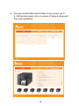
3. Prepare the documentation and software CD-Rom from
printer package and then install to CD-Rom drive of your
computer. The CD-Rom will bring out the following prompt.
Click “Go”:
57
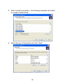
4. Choose Industrial Barcode Printers on the screen, go to
X-3200 product page, click on version of Seagull driver and
then start installation:
58
Instead of the flash prompt above, another way to install
Seagull driver is to run the DriverWizard utility from the
Installation Directory where the Seagull driver files locates.
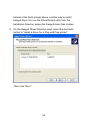
5. On the Seagull Driver Wizard prompt, select the first radio
button to “Install a driver for a Plug and Play printer”:
Then click “Next.”
59
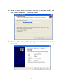
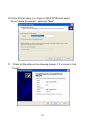
6. Enter Printer name (i.e. Argox X-3200 PPLB) and select "do
not share this printer”, and click "Next"
7. Check all the data on the showing screen, if it is correct, click
"Finish".
60
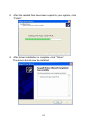
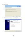
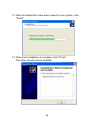
8. After the related files have been copied to your system, click
"Finish".
9. After driver installation is complete, click "Close".
The driver should now be installed.
61
Installing a Printer Driver (for other interfaces
except USB)
1. Turn off the printer. Plug the power cable into the power
socket on the wall, and then connect the other end of the
cable to printer's power socket. Connect the Parallel cable,
Serial cable, or Ethernet cable to the proper port on the printer
and on your computer.
2. Prepare the documentation and software CD-Rom from
printer package and then install to CD-Rom drive of your
computer. The CD-Rom will bring out the following prompt.
Click “Go”:
62
3. Choose Industrial Barcode Printers on the screen, go to
X-3200 product page, click on version of Seagull driver and
then start installation:
63
Instead of the flash prompt above, another way to install
Seagull driver is to run the DriverWizard utility from the
Installation Directory where the Seagull driver files locates.
4. On the prompt, Windows Printer Driver, select “I accept…”
and click "Next".
5. Assign the directory to keep Seagull driver, (for example:
C:\Seagull) and click "Next".
64
6. Click "Finish".
7. Select Install printer drivers and Click "Next"
65
8. Select model & emulation - the following examples are based
on model X-3200 PPLB:
9. Select the port of the printer and click "Next".
66
10. Enter Printer name (i.e. Argox X-3200 PPLB) and select
"do not share this printer”, and click "Next".
11. Check all the data on the showing screen, if it is correct, click
"Finish".
67
12. After the related files have been copied to your system, click
"Finish".
13. After driver installation is complete, click "Close".
The driver should now be installed.
68
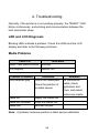
4. Troubleshooting
Normally, if the printer is in not working properly, the "READY" LED
blinks continuously, and printing and communication between the
host and printer stops.
LED and LCD Diagnosis
Blinking LEDs indicate a problem. Check the LEDs and the LCD
display and refer to the following solutions:
Media Problems
LED/LCD
Indication
READY and MEDIA LEDs
Blinking
LCD Display
MEDIA OUT
Possible Problems
Miss-detected gap
Solutions
Check the media path
Check the position of
the label sensor
Media out
Supply the media roll
Media not installed
Install the media roll
Media jam
Recover the jam
Remarks
For continuous
media, check
application and
driver, and select
continuous media.
Note: If problem continues perform a label sensor calibration.
69
Ribbon Problems
LED/LCD
Indication
READY and RIBBON LEDs Blinking
LCD Display
RIBBON OUT
Possible Problems
Solutions
Ribbon out
Supply the ribbon roll
Ribbon jam
Recover the jam
Remarks
Not applicable to
direct thermal.
Ribbon sensor error Replace ribbon sensor
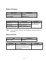
Note: If you use direct thermal, set with panel, Windows driver or
command.
Other Problems
LED
READY LED
Problems
Serial IO error
Indication
Blinking
Solutions
Remarks
Check the baud rate, format Not for Centronics
or protocol between host
and printer
70
Cutter failed
Check the media.
Check the connection
between cutter and main
board.
Call for service.
Memory full
Check graphics and soft
fonts from host. Delete by
application software for
those no longer in use.
Need to reboot the
system.
Note: After problem is solved, press CANCEL to continue printing.
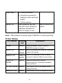
Printer Status
LCD display
PAUSE
Blinking
LED
Description
READY Printer is paused. Press PAUSE or
CANCEL to return to normal.
MEDIA OUT
MEDIA
READY
RIBBON OUT
Media is uninstalled or used up. Load new
media to the printer.
RIBBON Ribbon is uninstalled or end-of-ribbon
READY occurred. Load new ribbon to the printer.
SERIAL IO
ERROR
READY Format or baud rate of RS232
communication is inconsistent between
printer and host.
CUTTER FAILED READY Cutter cannot cut off the media, check
media and cutter.
MEMORY FULL
READY Printer buffer full due to loaded soft fonts,
71
graphics or forms. Check data format. Call
for service.
SENSOR O.R.
READY Media calibration is out of range for sensor
detection. Make sure media is loaded and
media sensor locates under media.
Printing job will start until the temperature
of TPH goes down.
PRINT HEAD
HEAT
MEDIA
HEAD OPEN
READY Print head latch is not closed. To print label
the head latch must be closed.
Transmission Problems
If the host shows "Printer Time out"
1. Check if the communication cable (parallel or serial) is
connected securely to your parallel or serial port on the PC
and to the connector on the printer at the other end.
2. Check if the printer power is turned on.
If the data has been sent, but there is no output from the printer.
Check the active printer driver, and see if Seagull Driver for your
Windows system and the label printer has been selected.
Recovery
After correcting problems, simply press the CANCEL button or
restart the printer. Make sure the LEDs are not blinking and
remember to resend your files.
72
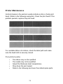
Printer Maintenance
Vertical streaks in the printout usually indicate a dirty or faulty print
head. (Refer to the following examples.) Clean the print head. If the
problem persists, replace the print head.
For unstable ribbon roll rotation, check the label path and make
sure the head latch is securely closed.
Poor printout quality:
The ribbon may not be qualified.
The media may not be qualified.
Adjust the Darkness (heat temperature).
Slow down the print speed.
Refer to the following and clean the related spare parts.
73
Cleaning the Print Head
To keep the Print Head remain in the best conditions and efficiency
and to extend duration for use, regular cleaning action is needed.
Note: Turn off the printer before cleaning.
Clean the print head as follows:
1. Turn off the printer.
2. Open the top cover to access the print head module
3. Remove the ribbon.
4. Rub the print head with a cotton bud moistened with
“Ethanol” or “IPA”.
5. Check for any traces of black coloring or adhesive on the
cotton after cleaning.
6. Repeat if necessary until the cotton is clean after it is
passed over the head.
Cleaning Interval
It’s strongly recommended to regularly clean print heads at least
when changing every one label roll (in direct thermal printing mode)
or every one ribbon roll (in thermal transfer printing mode). In
addition, if printers are operated under critical applications and
environments, or if it’s found that print quality is degraded, please
clean print heads more frequently.
Cleaning Material
Surface of print head’s heating element is very fragile. To prevent
from any possible damage, please use soft cloth/ cotton buds with
“Ethanol” or “IPA” to clean print head surface.
74
It’s strongly recommended to wear hand gloves during cleaning
progress.
Do not touch print head surface by bare hands or with any hard
equipment.
Water or spit should be kept away in case of corrosion on heating
elements.
Cleaning Direction
When cleaning the print head, always wipe in One-Way Direction from Left to Right only, or, from Right to Left only, to clean “Heating
Line” of print head gently without excessive stress.
Do not wipe back and forth, to avoid dust or dirt on cleaning cotton
would be attached onto print head again.
Special Caution:
Warranty of print heads will be void if print head serial number is
removed, altered, defected, or made illegible, under every
circumstance.
Cleaning the Roller
Using a cotton bud moistened with alcohol, clean the roll and
remove any attached glue.
Note: Clean the roller after it has been in contact with foreign
materials such as dust or adhesives.
Cleaning the Media Compartment
Clean the media compartment with a cotton bud that has been
moistened with a mild detergent. Every time a media roll is printed,
you should clean this compartment to reduce the incidence dust.
75
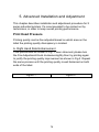
5. Advanced Installation and Adjustment
This chapter describes installation and adjustment procedure for X
series industrial printers. It’s recommended to be carried out by
technicians, in order to keep overall printing performance.
Print Head Pressure
Printing quality can be fine adjusted based on which area on the
label the printing quality discrepancy is located.
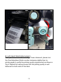
A. Right Hand Side Enhancement
If the phenomena as shown in Fig. 1 been observed, please turn
the Fine Adjustment Knob clockwise slightly then try printing again
to justify the printing quality improvement as shown in Fig.2. Repeat
the same process until the printing quality is well balanced on both
ends of the label.
Figure 1
Figure 2
76
B. Left Hand Side Enhancement
If the phenomena as shown in Fig. 3 been observed, please turn
the Fine Adjustment Knob counter-clockwise slightly then try
printing again to justify the printing quality improvement as shown in
Fig.4. Repeat the same process until the printing quality is well
balanced on both ends of the label.
77
Figure 3
Figure 4
Once the desired quality has been reached, please make note on
the new setting of the Fine Adjustment Knob and the type number
of ribbon been used in this printing task for future reference.
[Remark]:
Please note, as shown in Fig. 2 and Fig. 4, the Fine Adjustment
Knob is set to “ 0 “ as default setting when shipped from Argox
factory.
78
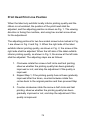
Print Head Print Line Position
When the label only exhibits locally inferior printing quality and the
ribbon is not wrinkled, the position of the print head shall be
adjusted, and the adjusting position is shown as Fig. 1. The viewing
direction is facing the machine, and using hex socket screw driver
for the adjustment.
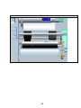
The adjusting portions for two hex socket screw locks marked in Fig.
1 are shown in Fig. 2 and Fig. 3. When the right side of the label
exhibits inferior printing quality, as shown in Fig. 2, the screw at the
right side shall be adjusted. When the left side of the label exhibits
inferior printing quality, as shown in Fig. 3, the screw at the left side
shall be adjusted. The adjusting steps are as follows:
1. Clockwise rotate the screw a half circle and test printing;
observe whether the printing quality has been gradually
improved or not; and stop the adjustment if the quality is
improved.
2. Repeat Step 1; if the printing quality has not been gradually
improved after five times, counterclockwise rotate five
circles back to the original position and then proceed Step
3.
3. Counter-clockwise rotate the screw a half circle and test
printing; observe whether the printing quality has been
gradually improved or not; and stop the adjustment if the
quality is improved.
79
Figure 1
80
Figure 2
Figure 3
81
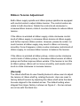
Ribbon Tension Adjustment
Both ribbon supply spindle and ribbon pickup spindle are equipped
with control knobs to adjust ribbon tension. The control knobs can
rotate to both directions. Rotate the control knob clockwise to
increase ribbon tension; rotate it counter-clockwise to reduce ribbon
tension.
If the ribbon is wrinkled at ribbon supply, rotate clockwise control
knob of ribbon supply, to increase ribbon tension at ribbon supply
and further improve ribbon wrinkle. However, please be noted, too
much tension at ribbon supply may result in ribbon not moving
smoothly. Once it happens, rotate counter-clockwise control knob of
ribbon supply, to increase ribbon tension to balance the tension.
If the ribbon is wrinkled at ribbon pickup, rotate counter-clockwise
control knob of ribbon pickup, to decrease ribbon tension at ribbon
pickup and further improve ribbon wrinkle. If the tension is too little
at ribbon pickup, ribbon will not move smoothly, and needs control
knob to rotate clockwise to increase tension.
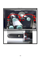
[Remark]:
The ribbon shaft has its user-friendly feature to allow users to adjust
the tension of ribbon shaft by rotating the knob. User can reset to
factory default tension by adjusting the ribbon shaft while the black
line was aligned to the marked arrows. The default setting when
shipped from Argox factory is shown as Figure 2 – the two arrows
are in line with the black line.
82
Figure 1
Figure 2
83
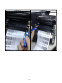
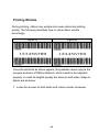
Printing Wrinkle
During printing, ribbon may wrinkle and cause abnormal printing
quality. The following describes how to solve ribbon wrinkle
accordingly.
Figure A
Figure B
Once the printouts as above appear, the possible cause may be the
unequal positions of Ribbon Bracket, which needs to be adjusted
properly to make its heights equally the same at both sides. Steps to
adjust are as below:
1. Loose the screws at both sides and rotate counter-clockwise:
84
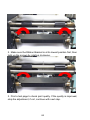
2. Make sure the Ribbon Bracket is at its lowest position first; then
tight up the screws by rotating clockwise.
3. Print a test page to check print quality. If the quality is improved,
stop the adjustment; if not, continue with next step.
85
4. If the test print appears as Figure A, remain the screw at the right
of Ribbon Bracket fixed, then loose the screw at the left, and
gradually fine-tune upward, until the print quality gets improved.
If the test print appears as Figure B, remain the screw at the left of
Ribbon Bracket fixed, and then loose the screw at the right, and
gradually fine-tune upward, until the print quality gets improved.
86
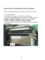
Rotary Cutter and Guillotine Cutter Installation
Refer to the following steps to install the cutter kit onto printers:
1. Turn off the printer.
2. Remove the top covers on both left and right sides.
3. Install the Cutter Baby Board to the main board JP17 socket of
X-1000VL, X-2000V, X-2000V Zip / JP15 socket of X-3200,
X-3200Z, X-3200E, X-3200ZE, X-2300E, X-2300ZE.
4. Loose the three screws from Tear-off Bracket and then remove
Tear Bracket.
Tear Bracket
screw
87
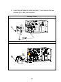
5. Insert the left side of cutter bracket (7) and secure the two
screws (6) to the print module.
Rotary Cutter
Guillotine Cutter
88
6. Thread the cutter cable through hole (8) and route it to the
JP16 connector (CUTTER) on the X-1000VL/ X-2000V/
X-2000V Zip main boards, or to the JP14 connector
(CUTTER) on the main board of X-3200/ X-3200Z/
X-3200E/ X-3200ZE/ X-2300E/ X-2300ZE.
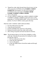
7. Turn on the printer.
8. For the X-2000V/ X-2000V Zip/ X-3200/ X-3200Z/ X-3200E/
X-3200ZE/ X-2300E/ X-2300ZE models with LCD, set the
parameter of “CUTTER INSTALLED” on the LCD to the ON
position. For the X-1000VL model, ignore this step.
After the cutter is installed, install media and ribbon.
1. Put the media end on the roller.
2. Close the print head latch.
3. Hold the PAUSE button and turn on the printer.
4. Release the button when the cutter starts cutting.
5. After cutting, the printer will feed the label for 8 inches.
Note: The procedure above is for first time installation or after
cutter jam. Normally the procedure for loading the media
through the cutter is:
1. Put the media end on the roller.
2. Close the print head latch.
3. Turn on the printer.
4. Press the FEED button to feed the media end through
the cutter.
89
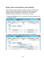
Rotary Cutter and Guillotine Cutter Settings
Before printing and cutting tasks, please make sure whether the
cutter in use is Rotary Cutter, or Guillotine Cutter. Then select
proper settings via Seagull Driver for printer. The following
installation steps are based on X-3200 as an example.
1. Check X-3200 driver. Go to the prompt of Printer Properties, click
on the tag, “Tools’:
2. Click the “Configure” setting of driver, select “Cutter Setup”:
90
3. “Cutter Setup” prompts will be indicated as below.
Check on the radio button, “Rotary” if there’s Rotary Cutter
installed.
Then click “OK“:
Check on the radio button, “Guillotine” if there’s Guillotine Cutter
installed. Then click “OK“:
91
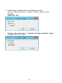
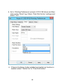
4. Go to “Printing Preference” prompt of CP-2140 driver and then
click on the “Stock” tag. Check “Post-Print Action” settings and
select “Cut”.
※ If there’s Guillotine Cutter installed and partial cut function is
needed, select “Partial Cut” in “Post-Print Action”.
92
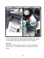
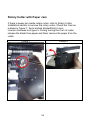
Rotary Cutter with Paper Jam
If there is paper jam inside rotary cutter, refer to Rotary Cutter
Installation section to remove the rotary cutter. Check the Cam as
marked in Figure 1, find a slotted screwdriver to turn
counter-clockwise as Figure 2. During turning the Cam of cutter,
release the blade from paper and them remove the paper from the
cutter.
Figure 1
Figure 2
93
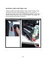
Guillotine Cutter with Paper Jam
If there is paper jam inside guillotine cutter, check in Figure 1 and
find where the screw under guillotine cutter. It is to control cut
actions of guillotine cutter. Find a Phillips screwdriver to lay down
the blade by turning the screw counter-clockwise. Then paper can
be removed from the cutter as Figure 2.
Figure 1
Figure 2
94
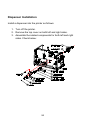
Dispenser Installation
Install a dispenser into the printer as follows:
1. Turn off the printer.
2. Remove the top cover on both left and right sides.
3. Assemble the related components for both left and right
sides. Check below:
95
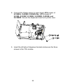
4. Connect the Peeler sensor to main board JP15 socket of
X-1000VL, X-2000V, X-2000V Zip / JP12 socket of
X-3200, X-3200Z, X-3200E, X-3200ZE, X-2300E, and
X-2300ZE. Secure the dispenser board onto printer case.
5. Insert the left side of dispenser bracket and secure the three
screws to the TPH module.
96
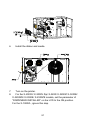
6.
7.
8.
Install the ribbon and media.
Turn on the printer.
For the X-2000V/ X-2000V Zip/ X-3200/ X-3200Z/ X-3200E/
X-3200ZE/ X-2300E/ X-2300ZE models, set the parameter of
“DISPENSER INSTALLED” on the LCD to the ON position.
For the X-1000VL, ignore this step.
97
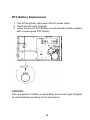
RTC Battery Replacement
1. Turn off the printer; disconnect the AC power cable.
2. Open the left cover of printer.
3. Loose the lock for RTC Battery on main board and then replace
with a known good RTC battery.
CAUTION:
Risk of explosion if battery is replaced by an incorrect type. Dispose
of used batteries according to the instructions.
98
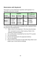
Stand-alone with Keyboard
This section covers stand-alone operation with keyboard. It is
applicable with printer models:
PS/2
Argokee
Keyboard
Printer
PPLA
PPLB
Basic
PPLB only
Language
X-1000VL X-1000VL
X-2000V
X-2000V
X-2000V
All
X-3200
Model
X-3200
X-3200
models X-2300E
X-2300E
X-2300E
X-3200E
X-3200E
X-3200E
To use the printer in stand-alone operation with a keyboard follow
the procedure described below:
1. Make a form for the keyboard. (The form should include
“ZS” command to store to flash memory. Refer to the
following command sample.)
2. Turn on the printer; download the form from PC to printer.
3. Turn off the printer.
4. Connect the keyboard to the keyboard interface.
5. Turn on the printer.
6. Check LCD for instructions of each data string/ label count/
copies; type to input data accordingly.
99
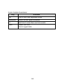
Form Control Functions:
Key
Function
Esc
Enter or exit from keyboard mode
Backspace
Delete the last typed character
F1
Next form if more than one form exists
Enter
- Select the form
- End of typed data
100
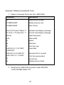
Example: Making a Keyboard Form
1. Make a command file for the form, KBD.FRM.
Command
Description
ZS
Enable store to flash
FK"KBDFORM"
Delete previous one
FS"KBDFORM"
Start of form
V00,15,N,"Product Name ?"
Variable and display message
C0,10,N,+1,"Product No. ?"
Counter and display message
Q50,24
Label dimension
q816
Label width
S2
Speed
D8
Darkness
ZT
Print from top
A550,20,0,4,1,1,R,"ABC
COMPANY"
Fixed data
B550,60,0,2,2,4,40,B,C0
Barcode I25 for counter
A540,150,0,3,1,1,N,V00
Print the input product
FE
End of form
ZN
Disable store to flash
2. Send the file, KBD.FRM to printer under MS-DOS
>COPY/B KBD.FRM LPT1:
101
3. Turn off the printer, connect the keyboard and then turn on
the printer. The LCD displays this message:
READY (203,PPLB)
<ESC> FOR KEYBD
4. Press <ESC> to enter the keyboard mode and the form
name appears. Press <ENTER> to select the form.
KBDFORM
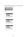
5. Key-in the product name and number.
Product Name ?
Barcode Printer
Product No. ?
0123456789
6. Input the label count and copy count.
LABEL SET NO. ?
2
COPIES PER LAB ?
3
102
7. Press <ENTER> to continue to the next label and repeat
steps 5 ~ 7, or <ESC> to exit.
ENTER to go on,
Or ESC to return
8. Output:
103
104
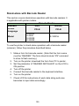
Stand-alone with Barcode Reader
This section covers stand-alone operation with barcode readers. It
is applicable with printer models:
Barcode Reader
Interface
PS/2
RS-232
Printer
PPLB
PPLB
Language
X-2000V
X-3200
Model
X-1000VL
X-2300E
X-3200E
To use the printer in stand-alone operation with a barcode reader
(scanner), follow the procedure described below
1. Make a form for barcode reader. (Note that the form name
must be “READER” The form should include “ZS” command
to store to flash memory.)
2. Turn on the printer; download the form from PC to printer.
3. Set the parameter of “READER INSTALLED” on the LCD to
ON position.
4. Turn off the printer.
5. Connect the barcode reader to the keyboard interface.
6. Turn on the printer.
7. Check LCD for instructions of each data string and scan
barcodes to input data accordingly.
105
Example: Making a Barcode Reader Form
1. Make a command file for a form, READER.FRM.
Command
Description
ZS
Enable store to flash
FK"READER"
Delete previous one
FS"READER"
Start of form
V00,15,N,"Product Name ?"
Variable and display message
C0,10,N,+1,"Product No. ?"
Counter and display message
Q50,24
Label dimension
q816
Label width
S2
Speed
D8
Darkness
ZT
Print from top
A550,20,0,4,1,1,R,"ABC
COMPANY"
Fixed data
B550,60,0,2,2,4,40,B,C0
Barcode I25 for counter
A540,150,0,3,1,1,N,V00
Print the input product
PA1
Single copy
FE
End of form
ZN
Disable store to flash
106
2. Send the file READER.FRM to printer under MS-DOS
>COPY/B READER.FRM LPT1:
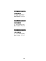
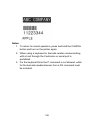
3. Turn off the printer, connect the barcode reader, turn on the
printer and set “Reader installed” on the LCD to ON
position.
4. The form READER is automatically executed. Scan product
name and number from printed bar codes using the barcode
reader.
Product No.?
11223344
Product Name?
APPLE
5. A label is printed. The copy count depends on the PA
command for the READER form. Step 4 is automatically
repeated.
6. Output:
107
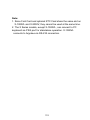
Notes:
1. To return to normal operation, press and hold the CANCEL
button and turn on the printer again.
2. When using a keyboard or barcode reader communicating
with a host through the Centronics or serial port is
prohibited.
3. For the keyboard form the P command is not allowed, while
for the barcode reader/scanner form a PA command must
be included.
108
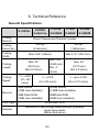
6. Technical Reference
General Specifications
X-1000VL
Printing
Method
Printing
Length
Printing
Speed
Memory
CPU Type
Sensors
X-2300E
X-3200
X-3200E
X-2000V Zip
X-2300ZE
X-3200Z
X-3200ZE
Direct Thermal and Thermal Transfer
203 dpi
300 dpi
(8 dots/mm)
(12dots/mm)
Max 4.09” (104mm)
Max 4.16” (105.7mm)
Printing
Resolution
Printing
Width
X-2000V
Max. 100”
Max. 50”
(2540 mm)
(1270 mm)
Min .2”
Min 0.2”(5mm)
2 ~ 4 IPS
(51~102
mm/s)
(5mm)
Max. 50”
(1270 mm)
Min 0.2”(5mm)
2 ~ 6 IPS
1 ~ up to 5 IPS
(51~152 mm/s)
(25.4~127 mm/s)
8MB DRAM
16 MB DRAM
(7MB User Available)
(13MB User Available)
4MB Flash ROM
8MBFlash ROM
(3MB User Available)
(6MB User Available)
32 bit RISC CPU
Reflective & See-through media sensors (movable)
Head open switch
Ribbon end sensor
109
Display
LED
indicator
x 3,
Button x 3
Centronics
parallel,
Communic
ation
interfaces
RS-232
serial
(baud rate
to 115200
bps),
LED indicator x 3, Button x 3,
Back-lit LCD Display 16 x 2-line
Multilingual
Centronics parallel,
RS-232 serial,
USB,
PS/2 interface,
Ethernet 10/100MB (X-2300E / X-2300ZE /
X-3200E / X-3200ZE)
USB
Media
Types
Roll-feed, die-cut, continuous, fan-fold, tags, ticket in thermal
paper or plain paper, fabric labels
Max. media width: 4.4” (112mm)
Maximum
Label
Roll
Diameter
Min. media width: 1” (25.4 mm)
Media thickness: 0.0025”~0.01”(0.0635mm~0.254mm)
8”(203mm) OD on a 3”(76mm) ID core
7”(177.8mm) OD on a 1.5”(38mm) ID core
Min Length: 0.79“(20mm) for rotary cutter option
Ribbon
Wax, Wax/Resin, Resin
(ribbon wound ink-side out or ink-side in available)
Ribbon width: 1”~4”(25.4 mm~101.6 mm)
Ribbon
Size
Ribbon Length: max 360m Wax, 300m Semi-Resin
Ribbon roll max OD 3” (76 mm)
Core size ID 1”(25.4 mm)
110
Compact
Size
W250 x L418 x H263 mm
Weight
24lbs(11kgs)
Power
Source
100~240 VAC, 50/60 Hz,
internal universal power supply
Operating Temperature 40 F~100F (4C~38C),
Operation
10% ~ 90% non-condensing,
Environment
Storage Temperature -4F~122F (-20C~50C)
Driver
Operating
Systems
Printer
Languages
Real Time
Clock
Win XP/ Vista/ Windows 7/ Windows 8
X-1000VL, X-2000V, X-2300E, X-3200, X-3200E: PPLA, PPLB
X-2000V Zip, X-2300ZE, X-3200Z, X-3200ZE : PPLZ
Standard
N/A
(Battery for RTC:
(RTC)
Options
and
Accessories
Agency
Listing
Type CR2032, +3V, 225mAh)
Guillotine Cutter
Rotary Cutter
Dispenser
Rewinder
Media Stacker
RTC
Font card
(Simplified Chinese,
Traditional Chinese,
Japanese, Korean)
Guillotine Cutter
Rotary Cutter
Dispenser
Rewinder
Media Stacker
CE, cULus, FCC class A, CCC, S-Mark, RoHS
111
Note:
1. Since Font Card and optional RTC Card share the same slot on
X-1000VL and X-2000V, they cannot be used at the same time.
2. The X Series models, except X-1000VL, can connect to PC
keyboard via PS/2 port for standalone operation. X-1000VL
connects to Argokee via RS-232 connection.
112
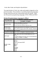
Fonts, Bar Codes and Graphics Specification
The specifications of fonts, bar codes and graphics depends on the
printer emulation. The emulation is a printer programming language
through which the host can communicate with your printer. There
are three printer programming languages, PPLA, PPLB and PPLZ.
Printer Programming Language A, PPLA
Specification
X-1000VL / X-2000V / X-3200 /
X-2300E / X-3200E
Internal Fonts
9 fonts with different point size
6 fonts with ASD smooth font.
Courier font with different symbol sets.
Symbol Sets
(Code Pages)
Courier font symbol set: Roman-8, ECMA-94, PC,
PC-A, PC-B, Legal, and PC437 (Greek), Russian.
Font Expandability 1x1 to 24x24
Character Rotation 0, 90, 180, 270 degree, 4 direction rotation
Soft Fonts
1D Bar Code
Types
True Type fonts can be downloaded by Font
Utility
(Two-byte Asian fonts also can be downloaded to
X-3200 / X-2300E / X-3200E)
Code 39
UPC-A
UPC-E
Code 128 subset A/B/C
EAN-13
EAN-8
HBIC
Codabar
Plessey
UPC2
UPC5
113
2D Bar Code
Types
Graphics
Code 93
Postnet
UCC/EAN-128
UCC/EAN-128 K-MART
UCC/EAN-128 Random Weight
Telepen
FIM
Interleave 2 of 5 (Standard/with modulo 10
checksum/with human readable check digit/with
modulo 10 checksum & shipping bearer bars)
GS1 Data bar (RSS)
MaxiCode
PDF417
Data Matrix (ECC 200 only)
QR code
Composite Codes
Aztec Barcode
Micro PDF417
PCX, BMP, IMG, GDI and HEX format files
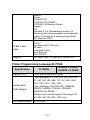
Printer Programming Language B, PPLB
Specification
Internal Fonts
X-1000VL
X-2000V / X-3200 /
X-2300E / X-3200E
5 fonts with different point sizes
8 bits code page: 437, 850, 852, 860, 863, 865,
857, 861, 862, 855, 866, 737, 851, 869, 1252,
1250, 1251, 1253, 1254, 1255
Symbol Sets
(Code Pages)
7 bits code page: USA, BRITISH, GERMAN,
FRENCH, DANISH, ITALIAN, SPANISH,
SWEDISH and SWISS.
(300dpi printer models support Code page 437,
850, 852, 860, 863, 865, 1254 only.)
Font Expandability 1x1 to 24x24
114
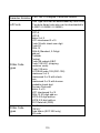
Character Rotation 0, 90, 180, 270 degree, 4 direction rotation
Soft Fonts
1D Bar Code
Types
2D Bar Code
Types
True Type fonts can be downloaded by Font Utility
(Two-byte Asian fonts also can be downloaded to
X-3200 / X-2300E / X-3200E)
Code 39
UPC-A
UPC-E
Matrx 2 of 5
UPC-Interleaved 2 of 5
Code 39 with check sum digit
Code 93
EAN-13
EAN-8 (Standard, 2 /5digit
add-on)
Codabar
Postnet
Code128 subset A/B/C
Code 128 UCC (shipping
container code)
Code 128 auto
UCC/EAN code 128 (GS1-128)
Interleave 2 of 5
Interleaved 2 of 5 with check
sum
Interleaved 2 of 5 with human
readable check digit
German Postcode
Matrix 2 of 5
UPC Interleaved 2 of 5
EAN-13 2/5 digit add-on
UPCA 2/5 digit add-on
UPCE 2/5 digit add-on
GS1 Data bar (RSS)
MaxiCode
PDF417
Data Matrix (ECC 200 only)
QR code
115
Graphics
Composite Codes
Aztec Barcode
PCX , Binary Raster, BMP and GDI
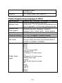
Printer Programming Language Z, PPLZ
Specification
Internal Fonts
Symbol sets
(Code pages)
Font size
X-2000V Zip / X-3200Z / X-2300ZE / X-3200ZE
8 (A~H) fonts with different point size.
8 AGFA fonts: 7 (P~V) fonts with fixed different point
size (not scalable). 1 (0) font with scaling point size.
USA1, USA2, UK, HOLLAND, DENMARK/NORWAY,
SWEDEN/FINLAND, GERMAN, FRANCE1,
FRANCE2, ITALY, SPAIN, MISC, JAPAN, IBM850.
1x1 to 10x10
Character Rotation 0, 90, 180, 270 degree, 4 direction rotation
Soft Fonts
1D Bar Code
Types
True Type fonts can be downloaded by Font Utility
(Two-byte Asian fonts also can be downloaded to
X-3200Z / X-2300ZE / X-3200ZE)
Code39
UPC-A
UPC-E
Postnet
Code128 subset A/B/C
Interleave 2 of 5
Interleaved 2 of 5 with check
sum
Interleaved 2 of 5 with human
readable check digit
Code 93
Code 39 with check sum digit
MSI
EAN-8
Codabar
Code 11
EAN-13
Plessey
116
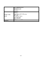
2D Bar Code
Types
Graphics
GS1 Data bar (RSS)
Industrial 2 of 5
Standard 2 of 5
Logmars
MaxiCode
PDF417
Data Matrix (ECC 200 only)
QR code
Composite Codes
Aztec Barcode
Micro PDF417
GRF, Hex and GDI
117
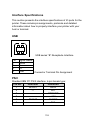
Interface Specifications
This section presents the interface specifications of IO ports for the
printer. These include pin assignments, protocols and detailed
information about how to properly interface your printer with your
host or terminal.
USB
2
1
3
4
USB series “B” Receptacle Interface
Pin
1
2
3
4
Signal Name
VBUS
DD+
GND
Connector Terminal Pin Assignment
PS/2
Standard IBM PC PS/2 interface, 6-pin female type:
Pin No.
Direction
Definition
IN/OUT
DATA
1
--N.C
2
--GROUND
3
--+5V
4
IN/OUT
CLOCK
5
--N.C
6
118
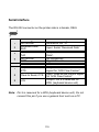
Serial Interface
The RS-232 connector on the printer side is a female, DB-9.
Pin
1
2
3
4
5
6
7
Signal
No function
Received Data,
RxD
Transmitted Data,
TxD
No function
GND
No function
Request to Send,
RTS
8
Clear to Send, CTS
9
+5V
Description
Shorted to Pin - 6
Input. Serial “Received Data”
Output. Serial “Transmitted
Data”.
No connection
Signal Ground
Shorted to Pin - 1
Output. Used as the control
signal for “H/W Flow Control “
Input. Used as the control signal
for “H/W Flow Control”
Output. Pin 9 is reserved for
KDU (keyboard device unit)
Note: Pin 9 is reserved for a KDU (keyboard device unit). Do not
connect this pin if you use a general host such as a PC.
119
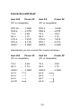
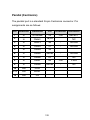
Connection with Host:
Host 25S
Printer 9P
(PC or compatible)
DTR 20
DSR 6
TX 2
RX 3
CTS 5
RTS 4
GND 7
……
……
……
……
……
……
……
1 DSR
6 DTR
2 RX
3 TX
7 RTS
8 CTR
5 GND
Host 9S
Printer 9P
(PC or compatible)
DTR 4
DSR 6
TX 3
RX 2
CTS 8
RTS 7
GND 5
……
……
……
……
……
……
……
1 DSR
6 DTR
2 RX
3 TX
7 RTS
8 CTS
5 GND
Alternatively you can connect the 3 wires as follows:
Host 25S
Printer 9P
(PC or compatible)
TX 2
RX 3
GND 7
pin 4
pin 5
pin 6
pin 20
…… 2 RX
…… 3 TX
…… 5 GND
Host 9S
Printer 9P
(PC or compatible)
TX 3
RX 2
GND 5
pin 4
pin 6
pin 7
pin 8
120
…… 2 RX
…… 3 TX
…… 5 GND
The simplest way to connect to other hosts (not PC compatible) or
terminals is:
Printer
Terminal/Host
Pin 2- RxData ………
TxData
Pin 3- TxData ………
RxData
Pin 5- Ground ………
Ground
In general, as long as the data quantity is not too large and you use
Xon/Xoff as flow control, it will be problem free.
Baud rate:
1200, 2400, 4800, 9600(default), 19200, 38400,
57600,115200 bauds. (Programmable by command)
Data format: always 8 data bits, 1 start bit and 1 stop bit.
Parity:
always non parity
Handshaking:
XON/XOFF as well as CTS/RTS (hardware flow
control).
If you run an application with the bundled printer driver under
Windows and use the serial port, you should check the above
parameters and set the flow control to "Xon/Xoff "or "hardware".
121
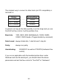
Parallel (Centronics)
The parallel port is a standard 36-pin Centronics connector. Pin
assignments are as follows:
Pin Direction
Definition
Pin
Direction
Definition
Out
SELECT
1
In
/STROBE
13
2
In
Data1
14,15
3
In
Data 2
16
-
Ground
4
In
Data3
17
-
Ground
5
In
Data4
18
6
In
Data5
19~30
-
Ground
7
In
Data6
31
8
In
Data7
32
Out
/Fault
9
In
Data8
33~36
-
NC
10
Out
/ACK
11t
Out
BUSY
12
Out
PE
122
NC
NC
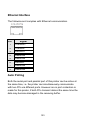
Ethernet Interface
The following port complies with Ethernet communication.
Pin
Signal
1
Transmit+
2
Transmit-
3
Receive+
4
Reserved
5
Reserved
6
Receive-
7
Reserved
8
Reserved
Auto Polling
Both the serial port and parallel port of this printer can be active at
the same time, i.e. the printer can simultaneously communicate
with two PCs via different ports. However as no port contention is
made for this printer, if both PCs transmit data at the same time the
data may become damaged in the receiving buffer.
123
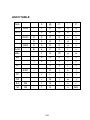
ASCII TABLE
NUL
0
@
P
'
P
!
1
A
Q
a
q
"
2
B
R
b
r
#
3
C
S
c
s
$
4
D
T
d
t
%
5
E
U
e
u
ACK
&
6
F
V
f
v
BEL
‛
7
G
W
g
w
BS
(
8
H
X
h
x
)
9
I
Y
i
y
*
:
J
Z
j
z
+
;
K
[
k
{
FF
,
<
L
\
l
I
CR
-
=
M
]
m
}
SOH
XON
STX
XOFF
NAK
LF
ESC
SO
RS
.
>
N
^
n
~
SI
US
/
?
O
_
o
DEL
124