1
Unified Access Point Administrator’s Guide
March 2012
Unified Access Point Administrator’s Guide
Page 1
Unified Access Point Administrator’s Guide
Table of Contents
Section 1 - About This Document.............................................................................................9
Document Organization.......................................................................................................................................... 9
Additional Documentation...................................................................................................................................... 9
Document Conventions.......................................................................................................................................... 9
Online Help, Supported Browsers, and Limitations.............................................................................................. 10
Section 2 - Getting Started.......................................................................................................11
Administrator’s Computer Requirements............................................................................................................. 11
Wireless Client Requirements.............................................................................................................................. 12
Dynamic and Static IP Addressing on the AP....................................................................................................... 13
Recovering an IP Address.............................................................................................................................. 13
Discovering a Dynamically Assigned IP Address........................................................................................... 13
Installing the UAP................................................................................................................................................. 13
Basic Settings....................................................................................................................................................... 16
Connecting to the AP Web Interface by Using the IPv6 Address................................................................... 17
Using the CLI to View the IP Address.................................................................................................................. 17
Configuring the Ethernet Settings........................................................................................................................ 18
Using the CLI to Configure Ethernet Settings................................................................................................ 18
Configuring IEEE 802.1X Authentication.............................................................................................................. 19
Using the CLI to Configure 802.1X Authentication Information...................................................................... 20
Verifying the Installation....................................................................................................................................... 20
Configuring Security on the Wireless Access Point.............................................................................................. 21
Section 3 - Viewing Access Point Status................................................................................22
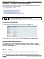
Viewing Interface Status....................................................................................................................................... 22
Wired Settings (Internal Interface)................................................................................................................. 22
Wireless Settings........................................................................................................................................... 22
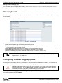
Viewing Events..................................................................................................................................................... 23
Configuring Persistent Logging Options......................................................................................................... 23
Configuring the Log Relay Host for Kernel Messages................................................................................... 24
Enabling or Disabling the Log Relay Host on the Events Page..................................................................... 24
Viewing Transmit and Receive Statistics.............................................................................................................. 25
Viewing Associated Wireless Client Information.................................................................................................. 26
Viewing TSPEC Client Associations..................................................................................................................... 26
Link Integrity Monitoring................................................................................................................................. 28
Viewing Rogue AP Detection............................................................................................................................... 28
Saving and Importing the Known AP List....................................................................................................... 30
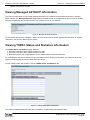
Viewing Managed AP DHCP Information............................................................................................................. 31
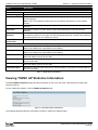
Viewing TSPEC Status and Statistics Information............................................................................................... 31
Viewing TSPEC AP Statistics Information............................................................................................................ 32
Viewing Radio Statistics Information.................................................................................................................... 33
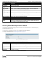
Viewing Email Alert Operational Status................................................................................................................ 34
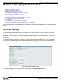
Section 4 - Managing the Access Point..................................................................................35
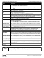
Ethernet Settings.................................................................................................................................................. 35
Wireless Settings.................................................................................................................................................. 37
Using the 802.11h Wireless Mode.................................................................................................................. 39
Enabling AeroScout™ Engine Support.......................................................................................................... 39
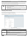
Modifying Radio Settings...................................................................................................................................... 40
Configuring Radio and VAP Scheduler................................................................................................................ 44
Scheduler Association Settings............................................................................................................................ 46
Virtual Access Point Settings................................................................................................................................ 47
None (Plain-text)............................................................................................................................................ 50
Static WEP..................................................................................................................................................... 50
IEEE 802.1X................................................................................................................................................... 51
WPA Personal................................................................................................................................................ 53
WPA Enterprise.............................................................................................................................................. 54
Configuring the Wireless Distribution System (WDS).......................................................................................... 56
WEP on WDS Links....................................................................................................................................... 58
WPA/PSK on WDS Links............................................................................................................................... 58
Unified Access Point Administrator’s Guide
Page 2
March 2012
Unified Access Point Administrator’s Guide
Controlling Access by MAC Authentication.......................................................................................................... 59
Configuring a MAC Filter and Station List on the AP..................................................................................... 59
Configuring MAC Authentication on the RADIUS Server............................................................................... 60
Configuring Load Balancing................................................................................................................................. 60
Managed Access Point Overview......................................................................................................................... 61
Transitioning Between Modes........................................................................................................................ 61
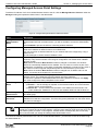
Configuring Managed Access Point Settings................................................................................................. 62
Configuring 802.1X Authentication....................................................................................................................... 63
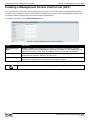
Creating a Management Access Control List (ACL)............................................................................................. 64
Section 5 - Configuring Access Point Services.....................................................................65
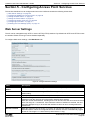
Web Server Settings............................................................................................................................................ 65
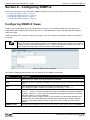
Configuring SNMP on the Access Point............................................................................................................... 66
Setting the SSH Status......................................................................................................................................... 68
Setting the Telnet Status...................................................................................................................................... 69
Configuring Quality of Service.............................................................................................................................. 69
Configuring Email Alert......................................................................................................................................... 72
Enabling the Time Settings (NTP)........................................................................................................................ 73
Section 6 - Configuring SNMPv3.............................................................................................75
Configuring SNMPv3 Views................................................................................................................................. 75
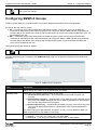
Configuring SNMPv3 Groups............................................................................................................................... 76
Configuring SNMPv3 Users................................................................................................................................. 77
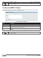
Configuring SNMPv3 Targets............................................................................................................................... 78
Section 7 - Maintaining the Access Point...............................................................................79
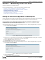
Saving the Current Configuration to a Backup File.............................................................................................. 79
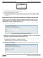
Restoring the Configuration from a Previously Saved File................................................................................... 80
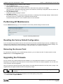
Performing AP Maintenance................................................................................................................................. 81
Resetting the Factory Default Configuration.................................................................................................. 81
Rebooting the Access Point........................................................................................................................... 81
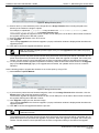
Upgrading the Firmware....................................................................................................................................... 81
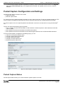
Packet Capture Configuration and Settings......................................................................................................... 83
Packet Capture Status................................................................................................................................... 83
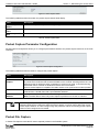
Packet Capture Parameter Configuration...................................................................................................... 84
Packet File Capture........................................................................................................................................ 84
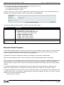
Remote Packet Capture................................................................................................................................. 85
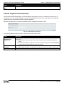
Packet Capture File Download....................................................................................................................... 87
Section 8 - Configuring Client Quality of Service (QoS).......................................................88
Configuring VAP QoS Parameters....................................................................................................................... 88
Managing Client QoS ACLs.................................................................................................................................. 89
IPv4 and IPv6 ACLs....................................................................................................................................... 89
MAC ACLs...................................................................................................................................................... 90
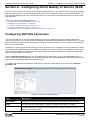
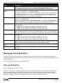
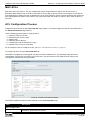
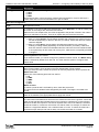
ACL Configuration Process............................................................................................................................ 90
Creating a DiffServ Class Map............................................................................................................................. 95
Defining DiffServ............................................................................................................................................ 96
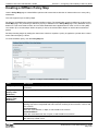
Creating a DiffServ Policy Map.......................................................................................................................... 100
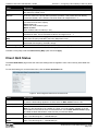
Client QoS Status............................................................................................................................................... 101
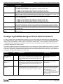
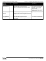
Configuring RADIUS-Assigned Client QoS Parameters.................................................................................... 102
Section 9 - Clustering Multiple APs......................................................................................104
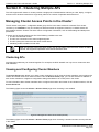
Managing Cluster Access Points in the Cluster.................................................................................................. 104
Clustering APs.............................................................................................................................................. 104
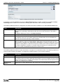
Viewing and Configuring Cluster Members.................................................................................................. 104
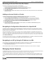
Removing an Access Point from the Cluster................................................................................................ 106
Adding an Access Point to a Cluster............................................................................................................ 106
Navigating to Configuration Information for a Specific AP........................................................................... 106
Navigating to an AP by Using its IP Address in a URL................................................................................. 106
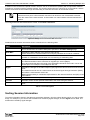
Managing Cluster Sessions................................................................................................................................ 106
Sorting Session Information......................................................................................................................... 107
Configuring and Viewing Channel Management Settings.................................................................................. 108
Stopping/Starting Automatic Channel Assignment....................................................................................... 108
Viewing Current Channel Assignments and Setting Locks.......................................................................... 109
March 2012
Unified Access Point Administrator’s Guide
Page 3
Unified Access Point Administrator’s Guide
Viewing the Last Proposed Set of Changes................................................................................................. 109
Configuring Advanced Settings.................................................................................................................... 109
Viewing Wireless Neighborhood Information..................................................................................................... 110
Viewing Details for a Cluster Member.......................................................................................................... 112
Appendix A - Default AP Settings..........................................................................................113
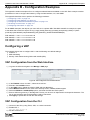
Appendix B - Configuration Examples.................................................................................115
Configuring a VAP.............................................................................................................................................. 115
VAP Configuration from the Web Interface.................................................................................................. 115
VAP Configuration from the CLI................................................................................................................... 115
VAP Configuration Using SNMP.................................................................................................................. 116
Configuring Radio Settings................................................................................................................................. 116
Radio Configuration from the Web Interface................................................................................................ 117
Radio Configuration from the CLI................................................................................................................. 117
Radio Configuration Using SNMP................................................................................................................ 118
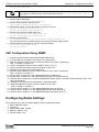
Configuring the Wireless Distribution System.................................................................................................... 118
WDS Configuration from the Web Interface................................................................................................. 118
WDS Configuration from the CLI.................................................................................................................. 119
WDS Configuration Using SNMP................................................................................................................. 119
Clustering Access Points.................................................................................................................................... 119
Clustering APs by Using the Web Interface................................................................................................. 119
Clustering APs by Using the CLI.................................................................................................................. 120
Clustering APs by Using SNMP................................................................................................................... 120
Configuring Client QoS ...................................................................................................................................... 121
Configuring QoS by Using the Web Interface.............................................................................................. 121
Configuring QoS by Using the CLI............................................................................................................... 124
Appendix C - Statements.......................................................................................................127
March 2012
Unified Access Point Administrator’s Guide
Page 4
Unified Access Point Administrator’s Guide
List of Figures
Figure 1 - Administrator UI Online Help.................................................................................................................... 10
Figure 2 - Web UI Login Prompt............................................................................................................................... 14
Figure 3 - Provide Basic Settings............................................................................................................................. 15
Figure 4 - Command Line Interface (CLI) Connection............................................................................................. 18
Figure 5 - Viewing Interface Status.......................................................................................................................... 22
Figure 6 - Viewing Events......................................................................................................................................... 23
Figure 7 - Viewing Traffic Statistics.......................................................................................................................... 25
Figure 8 - Viewing Client Association Information.................................................................................................... 26
Figure 9 - Viewing TSPEC Client Associations........................................................................................................ 27
Figure 10 - Viewing Rogue and Known Access Points............................................................................................ 28
Figure 11 - Managed AP DHCP Information............................................................................................................. 31
Figure 12 - Viewing TSPEC Status and Statistics.................................................................................................... 31
Figure 13 - View TSPEC Status and Statistics......................................................................................................... 32
Figure 14 - View Radio Statistics.............................................................................................................................. 33
Figure 15 - Email Alert Operational Status............................................................................................................... 34
Figure 16 - Modify Ethernet (Wired) settings............................................................................................................ 35
Figure 17 - Modify Wireless Settings........................................................................................................................ 37
Figure 18 - Modify Radio Settings............................................................................................................................ 40
Figure 19 - Scheduler Configuration........................................................................................................................ 45
Figure 20 - Scheduler Configuration (Modify Rule).................................................................................................. 46
Figure 21 - Scheduler Association Settings.............................................................................................................. 46
Figure 22 - Modify Virtual Access Point Settings...................................................................................................... 48
Figure 23 - Modify Virtual Access Point Settings (Static WEP)................................................................................ 50
Figure 24 - Modify Virtual Access Point Settings (IEEE802.1X)............................................................................... 52
Figure 25 - Modify Virtual Access Point Settings (WPA Personal)........................................................................... 53
Figure 26 - Modify Virtual Access Point Settings (WPA Enterprise)......................................................................... 54
Figure 27 - Configure WDS Bridges......................................................................................................................... 57
Figure 28 - Configure MAC Authentication............................................................................................................... 59
Figure 29 - Modify Load Balancing Settings............................................................................................................. 60
Figure 30 - Configure Managed AP Wireless Switch Parameters............................................................................ 62
Figure 31 - Modify 802.1X Supplicant Authentication Settings................................................................................. 63
Figure 32 - Configure Management Access Control Parameters............................................................................. 64
Figure 33 - Configure Web Server Settings.............................................................................................................. 65
Figure 34 - SNMP Configuration.............................................................................................................................. 67
Figure 35 - Set SSH Status...................................................................................................................................... 68
Figure 36 - Set Telnet Status.................................................................................................................................... 69
Figure 37 - Modify QoS Queue Parameters............................................................................................................. 70
Figure 38 - Email Alerts Configuration...................................................................................................................... 72
Figure 39 - Time Settings (NTP)............................................................................................................................... 74
Figure 40 - SNMPv3 Views Configuration................................................................................................................ 75
Figure 41 - SNMPv3 Groups Configuration.............................................................................................................. 76
Figure 42 - SNMPv3 User Configuration.................................................................................................................. 77
Figure 43 - SNMPv3 Targets Configuration.............................................................................................................. 78
Figure 44 - Manage this Access Point’s Configuration - Save (TFTP)..................................................................... 79
Figure 45 - Manage this Access Point’s Configuration - Save (HTTP)..................................................................... 79
Figure 46 - Confirmation Prompt.............................................................................................................................. 80
Figure 47 - Manage this Access Point’s Configuration - Restore (TFTP)................................................................. 80
Figure 48 - Manage this Access Point’s Configuration - Restore (HTTP)................................................................ 80
Figure 49 - Performing AP Maintenance.................................................................................................................. 81
Figure 50 - Manage Firmware (TFTP)...................................................................................................................... 82
Figure 51 - Manage Firmware (HTTP)..................................................................................................................... 82
Figure 52 - Packet Capture Configuration & Settings.............................................................................................. 83
Figure 53 - Packet Capture Status........................................................................................................................... 84
Figure 54 - Packet Capture Configuration................................................................................................................ 84
Figure 55 - Packet File Capture............................................................................................................................... 85
Figure 56 - Remote Packet Capture......................................................................................................................... 86
Figure 57 - Packet Capture File Download.............................................................................................................. 87
Figure 58 - Configure Client QoS VAP Settings....................................................................................................... 88
Figure 59 - Configure Client QoS ACL Settings....................................................................................................... 90
March 2012
Unified Access Point Administrator’s Guide
Page 5
Unified Access Point Administrator’s Guide
Figure 60 - Configure Client QoS DiffServ Class Map Settings............................................................................... 96
Figure 61 - Configure Client QoS DiffServ Policy Map Settings............................................................................. 100
Figure 62 - QoS Configuration Status For Associated Clients............................................................................... 101
Figure 63 - Manage Access Points In The Cluster (Passive)................................................................................. 104
Figure 64 - Manage Access Points In The Cluster (Active).................................................................................... 105
Figure 65 - Manage Sessions Associated With The Cluster.................................................................................. 107
Figure 66 - Automatically Manage Channel Assignments...................................................................................... 108
Figure 67 - View Neighboring Access Points...........................................................................................................111
Figure 68 - Viewing Details For A Cluster Member................................................................................................. 112
Figure 69 - VAP Configuration from the Web Interface.......................................................................................... 115
Figure 70 - Radio Configuration from the Web Interface........................................................................................ 117
Figure 71 - WDS Configuration from the Web Interface......................................................................................... 118
Figure 72 - Clustering APs by Using the Web Interface (Passive)......................................................................... 119
Figure 73 - Clustering APs by Using the Web Interface (Active)............................................................................ 120
Figure 74 - Configuring QoS by Using the Web Interface (ACL Name)................................................................. 121
Figure 75 - Configuring QoS by Using the Web Interface (Rule1)......................................................................... 121
Figure 76 - Configuring QoS by Using the Web Interface (Rule2)......................................................................... 122
Figure 77 - Configuring QoS by Using the Web Interface (VAP QoS Parameters)................................................ 122
Figure 78 - Configuring QoS by Using the Web Interface (Class Map Name)....................................................... 123
Figure 79 - Configuring QoS by Using the Web Interface (Rule)........................................................................... 123
Figure 80 - Configure Client QoS DiffServ Policy Map Settings (Policy Map Name)............................................. 123
Figure 81 - Configure Client QoS DiffServ Policy Map Settings (Rule).................................................................. 124
Figure 82 - Configure Client QoS VAP Settings..................................................................................................... 124
March 2012
Unified Access Point Administrator’s Guide
Page 6
Unified Access Point Administrator’s Guide
List of Tables
Table 1 - Typographical Conventions....................................................................................................................... 10
Table 2 - Requirements for the Administrator’s Computer........................................................................................ 12
Table 3 - Requirements for Wireless Clients............................................................................................................ 12
Table 4 - Basic Settings Page.................................................................................................................................. 17
Table 5 - CLI Commands for Ethernet Setting ......................................................................................................... 19
Table 6 - CLI Commands for the 802.1X Supplicant................................................................................................ 20
Table 7 - Logging Options........................................................................................................................................ 24
Table 8 - Log Relay Host.......................................................................................................................................... 24
Table 9 - Transmit/Receive....................................................................................................................................... 26
Table 10 - Associated Clients................................................................................................................................... 26
Table 11 - TSPEC Client Associations...................................................................................................................... 28
Table 12 - Rogue AP Detection................................................................................................................................ 30
Table 13 - TSPEC Status and Statistics................................................................................................................... 32
Table 14 - TSPEC AP Statistics................................................................................................................................ 33
Table 15 - Radio Statistics Information..................................................................................................................... 34
Table 16 - Email Alert Status.................................................................................................................................... 34
Table 17 - Ethernet Settings..................................................................................................................................... 36
Table 18 - Wireless Settings..................................................................................................................................... 39
Table 19 - Radio Settings......................................................................................................................................... 44
Table 20 - Scheduler Configuration.......................................................................................................................... 45
Table 21 - Scheduler Association Settings............................................................................................................... 47
Table 22 - Virtual Access Point Settings................................................................................................................... 50
Table 23 - Static WEP............................................................................................................................................... 51
Table 24 - IEEE 802.1X............................................................................................................................................ 53
Table 25 - WPA Personal.......................................................................................................................................... 54
Table 26 - WPA Enterprise........................................................................................................................................ 56
Table 27 - WDS Settings.......................................................................................................................................... 57
Table 28 - WEP on WDS Links................................................................................................................................. 58
Table 29 - WPA/PSK on WDS Links......................................................................................................................... 58
Table 30 - MAC Authentication................................................................................................................................. 60
Table 31 - RADIUS Server Attributes for MAC Authentication.................................................................................. 60
Table 32 - Load Balancing........................................................................................................................................ 61
Table 33 - Managed Access Point............................................................................................................................ 62
Table 34 - IEEE 802.1X Supplicant Authentication................................................................................................... 63
Table 35 - Management ACL.................................................................................................................................... 64
Table 36 - Web Server Settings................................................................................................................................ 66
Table 37 - SNMP Settings........................................................................................................................................ 68
Table 38 - SSH Settings........................................................................................................................................... 69
Table 39 - Telnet Settings......................................................................................................................................... 69
Table 40 - QoS Settings........................................................................................................................................... 72
Table 41 - Email Alert Configuration......................................................................................................................... 73
Table 42 - NTP Settings............................................................................................................................................ 74
Table 43 - SNMPv3 Views........................................................................................................................................ 75
Table 44 - SNMPv3 Groups...................................................................................................................................... 77
Table 45 - SNMPv3 Users........................................................................................................................................ 77
Table 46 - SNMPv3 Targets...................................................................................................................................... 78
Table 47 - Packet Capture Status............................................................................................................................. 84
Table 48 - Packet Capture Configuration................................................................................................................. 84
Table 49 - Packet File Capture................................................................................................................................. 85
Table 50 - Remote Packet Capture.......................................................................................................................... 87
Table 51 - Packet Capture File Download................................................................................................................ 87
Table 52 - VAP QoS Parameters.............................................................................................................................. 89
Table 53 - ACL Configuration.................................................................................................................................... 95
Table 54 - DiffServ Class Map.................................................................................................................................. 99
Table 55 - DiffServ Policy Map............................................................................................................................... 101
Table 56 - Client QoS Status.................................................................................................................................. 102
Table 57 - Client QoS RADIUS Attributes............................................................................................................... 103
Table 58 - Access Points in the Cluster.................................................................................................................. 105
Table 59 - Cluster Options...................................................................................................................................... 105
March 2012
Unified Access Point Administrator’s Guide
Page 7
Unified Access Point Administrator’s Guide
Table 60 - Session Management............................................................................................................................ 107
Table 61 - Channel Assignments............................................................................................................................ 109
Table 62 - Last Proposed Changes........................................................................................................................ 109
Table 63 - Advanced Channel Management Settings............................................................................................ 110
Table 64 - Wireless Neighborhood Information.......................................................................................................111
Table 65 - Cluster Member Details......................................................................................................................... 112
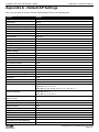
Table 66 - UAP Default Settings............................................................................................................................. 114
March 2012
Unified Access Point Administrator’s Guide
Page 8
Unified Access Point Administrator’s Guide
Section 1 - About This Document
Section 1 - About This Document
This guide describes setup, configuration, administration and maintenance for the D-Link DWL-x600AP Unified Access
Point (UAP) on a wireless network.
Document Organization
The Unified Access Point Administrator’s Guide contains the following sections:
•)“Section 1 - About This Document” on page 9
•)“Section 2 - Getting Started” on page 11
•)“Section 3 - Viewing Access Point Status” on page 22
•)“Section 4 - Managing the Access Point” on page 35
•)“Section 5 - Configuring Access Point Services” on page 65
•)“Section 6 - Configuring SNMPv3” on page 75
•)“Section 7 - Maintaining the Access Point” on page 79
•)“Section 8 - Configuring Client Quality of Service (QoS)” on page 88
•)“Section 9 - Clustering Multiple APs” on page 104
•)“Appendix A - Default AP Settings” on page 113
•)“Appendix B - Configuration Examples” on page 115
Additional Documentation
The following documentation provides additional information about Unified Access Point software:
•) The Unified Access Point CLI Command Reference describes the commands available from the command-line
interface (CLI) for managing, monitoring, and configuring the switch.
•) The User Manual for the D-Link Unified Wired and Wireless System provides information about setting up and
managing the Unified Wireless Switch (UWS), including information about how to use the switch to manage
multiple UAPs.
•) Release notes for the D-Link Unified Wired and Wireless System detail the platform-specific functionality of the
software packages, including issues and workarounds.
Document Conventions
This section describes the conventions this document uses.
Note: A note provides more information about a feature or technology and cross-references to
related topics.
Caution! A caution provides information about critical aspects of AP configuration, combinations of
settings, events, or procedures that can adversely affect network connectivity, security, and so on.
The following table describes the typographical conventions used in this guide.
Symbol
Example
Description
Bold
Click Apply to save your settings.
Menu titles, page names, and button names.
Blue Text
See “Document Conventions” on
page 9
Hyperlink text.
Courier Font
WLAN-AP# show network
Screen text, file names, commands, user-typed
command-line entries.
Courier Font
Italics
Value
Command parameter, which might be a variable or
fixed value.
Square Brackets [ ]
[Value]
Indicates an optional fixed parameter.
March 2012
Unified Access Point Administrator’s Guide
Page 9
Unified Access Point Administrator’s Guide
Section 1 - About This Document
Symbol
Example
Description
Curly Braces {}
{Choice1 | Choice2}
Indicates that you must select a parameter from the
list of choices.
Vertical Bars |
Choice1 | Choice2
Separates the mutually exclusive choices.
Braces within square
brackets [{}]
[{Choice1 | Choice2}]
Indicate a choice within an optional element.
Table 1 - Typographical Conventions
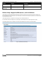
Online Help, Supported Browsers, and Limitations
Online help for the UAP Administration Web pages provides information about all fields and features available from
the user interface (UI). The information in the online help is a subset of the information available in the Unified Access
Point Administrator’s Guide.
Online help information corresponds to each page on the UAP Administration UI.
For information about the settings on the current page, click the Help link on the upper right side of a page.
The following figure shows an example of the online help available from the links on the user interface.
Figure 1 - Administrator UI Online Help
March 2012
Unified Access Point Administrator’s Guide
Page 10
Unified Access Point Administrator’s Guide
Section 2 - Getting Started
Section 2 - Getting Started
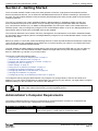
The D-Link DWL-x600AP unified access point (UAP) provides continuous, high-speed access between wireless
devices and Ethernet devices. It is an advanced, standards-based solution for wireless networking in businesses of
any size. The UAP enables wireless local area network (WLAN) deployment while providing state-of-the-art wireless
networking features.
The UAP can operate in two modes: Standalone Mode or Managed Mode. In Standalone Mode, the UAP acts
as an individual access point in the network, and you manage it by using the Administrator Web User Interface
(UI), command-line interface (CLI), or SNMP. In Managed Mode, the UAP is part of the D-Link Unified Wired and
Wireless System, and you manage it by using the D-Link Unified Wireless Switch. If an AP is in Managed Mode, the
Administrator Web UI, Telnet, SSH, and SNMP services are disabled.
This document describes how to perform the setup, management, and maintenance of the UAP in Standalone Mode.
For information about configuring the AP in Managed Mode by using the D-Link Unified Wireless Switch, see the User
Manual for the switch.
Before you power on a new UAP, review the following sections to check required hardware and software components,
client configurations, and compatibility issues. Make sure you have everything you need for a successful launch and
test of your new or extended wireless network.
The DWL-6600AP and DWL-8600AP are dual-radio access points and support the IEEE 802.11a, 802.11b, 802.11g,
and 802.11n modes. The DWL-2600AP and DWL-3600AP are single-radio access points and support the IEEE
802.11b, IEEE 802.11g, and 802.11n (2.4 GHz) modes.
This section contains the following topics:
•)“Administrator’s Computer Requirements” on page 11
•)“Wireless Client Requirements” on page 12
•)“Dynamic and Static IP Addressing on the AP” on page 13
•)“Installing the UAP” on page 13
•)“Basic Settings” on page 16
•)“Using the CLI to View the IP Address” on page 17
•)“Configuring the Ethernet Settings” on page 18
•)“Configuring IEEE 802.1X Authentication” on page 19
•)“Verifying the Installation” on page 20
•)“Configuring Security on the Wireless Access Point” on page 21
To manage the UAP by using the Web interface or by using the CLI through Telnet or SSH, the AP needs an IP
address. If you use VLANs or IEEE 802.1X Authentication (port security) on your network, you might need to configure
additional settings on the AP before it can connect to the network.
Note: The WLAN AP is not designed to function as a gateway to the Internet. To connect your
WLAN to other LANs or the Internet, you need a gateway device.
Administrator’s Computer Requirements
The following table describes the minimum requirements for the administrator’s computer for configuration and
administration of the UAP through a Web-based user interface (UI).
Required Software or Component
Description
Serial or Ethernet Connection to the
Access Point
The computer used to configure the first access point must be connected
to the access point by a serial cable or an Ethernet cable.
March 2012
Unified Access Point Administrator’s Guide
Page 11
Unified Access Point Administrator’s Guide
Section 2 - Getting Started
Required Software or Component
Description
Wireless Connection to the Network
After initial configuration and launch of the first access point on your
new wireless network, you can make subsequent configuration changes
through the Administration Web pages using a wireless connection to the
internal network.
For wireless connection to the access point, your administration device will
need Wi-Fi capability similar to that of any wireless client:
•) Portable or built-in Wi-Fi client adapter that supports one or more of
the IEEE 802.11 modes in which you plan to run the access point.
•) Wireless client software configured to associate with the UAP.
Web Browser and Operating System
Configuration and administration of the UAP is provided through a Webbased user interface hosted on the access point.
We recommend using one of the following supported Web browsers to
access the access point Administration Web pages:
•) Microsoft® Internet Explorer® version 7.x or 8.x (with up-to-date patch
level for either major version)
•) Mozilla® Firefox version 3.5 or later
•) Safari 5 and later versions
The administration Web browser must have JavaScript™ enabled to
support the interactive features of the administration interface.
Security Settings
Ensure that security is disabled on the wireless client used to initially
configure the access point.
Table 2 - Requirements for the Administrator’s Computer
Wireless Client Requirements
The UAP provides wireless access to any client with a properly configured Wi-Fi client adapter for the 802.11 mode
in which the access point is running. The UAP supports multiple client operating systems. Clients can be laptop or
desktop computers, personal digital assistants (PDAs), or any other hand-held, portable or stationary device equipped
with a Wi-Fi adapter and supporting drivers.
To connect to the access point, wireless clients need the software and hardware described in the following table.
Required Component
Description
Wi-Fi Client Adapter
Portable or built-in Wi-Fi client adapter that supports one or more of the
IEEE 802.11 modes in which you plan to run the access point.
Wireless Client Software
Client software, such as Microsoft Windows Supplicant, configured to
associate with the UAP.
Client Security Settings
Security should be disabled on the client used to do initial configuration of
the access point.
If the Security mode on the access point is set to anything other than plain
text, wireless clients will need to set a profile to the authentication mode
used by the access point and provide a valid username and password,
certificate, or similar user identity proof. Security modes are Static WEP,
IEEE 802.1X, WPA with RADIUS server, and WPA-PSK.
For information about configuring security on the access point, see “Virtual
Access Point Settings” on page 47.
Table 3 - Requirements for Wireless Clients
March 2012
Unified Access Point Administrator’s Guide
Page 12
Unified Access Point Administrator’s Guide
Section 2 - Getting Started
Dynamic and Static IP Addressing on the AP
When you power on the access point, the built-in DHCP client searches for a DHCP server on the network in order
to obtain an IP Address and other network information. If the AP does not find a DHCP server on the network, the AP
continues to use its default Static IP Address (10.90.90.91) until you re-assign it a new static IP address (and specify a
static IP addressing policy) or until the AP successfully receives network information from a DHCP server.
To change the connection type and assign a static IP address by using the CLI, see “Configuring the Ethernet
Settings” on page 18 or, by using the Web UI, see “Ethernet Settings” on page 35.
Caution! If you do not have a DHCP server on your internal network, and do not plan to use one,
the first thing you must do after powering on the access point is change the connection type from
DHCP to static IP. You can either assign a new static IP address to the AP or continue using the
default address. We recommend assigning a new static IP address so that if you bring up another
WLAN AP on the same network, the IP address for each AP will be unique.
Recovering an IP Address
If you experience trouble communicating with the access point, you can recover a static IP address by resetting the AP
configuration to the factory defaults (see “Resetting the Factory Default Configuration” on page 81), or you can get
a dynamically assigned address by connecting the AP to a network that has a DHCP server.
Discovering a Dynamically Assigned IP Address
If you have access to the DHCP server on your network and know the MAC address of your AP, you can view the new
IP address associated with the MAC address of the AP.
If you do not have access to the DHCP server that assigned the IP address to the AP or do not know the MAC address
of the AP, you might need to use the CLI to find out what the new IP address is. For information about how to discover
a dynamically assigned IP address, see “Using the CLI to View the IP Address” on page 17.
Installing the UAP
To access the Administration Web UI, you enter the IP address of the AP into a Web browser. You can use the default
IP address of the AP (10.90.90.91) to log on to the AP and assign a static IP address, or you can use a DHCP server
on you network to assign network information to the AP. The DHCP client on the AP is enabled by default.
To install the UAP, use the following steps:
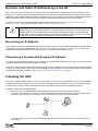
1.) Connect the AP to an administrative PC by using a LAN connection or a direct-cable connection.
•)To use a LAN connection, connect one end of an Ethernet cable to the network port on the access point and
the other end to the same hub where your PC is connected, as shown in the following figure.
The hub or switch you use must permit broadcast signals from the access point to reach all other devices on
the network.
March 2012
Unified Access Point Administrator’s Guide
Page 13
Unified Access Point Administrator’s Guide
Section 2 - Getting Started
•)To use a direct-cable connection, connect one end of an Ethernet straight-through or crossover cable to the
network port on the access point and the other end of the cable to the Ethernet port on the PC, as shown in
the following figure. You can also use a serial cable to connect the serial port on the AP to a serial port on the
administrative computer.
For initial configuration with a direct Ethernet connection and no DHCP server, be sure to set your PC to a
static IP address in the same subnet as the default IP address on the access point. (The default IP address for
the access point is 10.90.90.91.)
If you use this method, you will need to reconfigure the cabling for subsequent startup and deployment of the
access point so that the access point is no longer connected directly to the PC but instead is connected to the
LAN (either by using a hub or directly).
Note: It is possible to detect access points on the network with a wireless connection. However,
we strongly advise against using this method. In most environments you may have no way
of knowing whether you are actually connecting to the intended AP. Also, many of the initial
configuration changes required will cause you to lose connectivity with the AP over a wireless
connection.
2.) Connect the power adapter to the power port on the back of the access point, and then plug the other end of the
power cord into a power outlet.
3.) Use your Web browser to log on to the UAP Administration Web pages.
•)If the AP did not acquire an IP address from a DHCP server on your network, enter 10.90.90.91 in the address
field of your browser, which is the default IP address of the AP.
•)If you used a DHCP server on your network to automatically configure network information for the AP, enter the
new IP address of the AP into the Web browser.
•)If you used a DHCP server and you do not know the new IP address of the AP, use the following procedures to
obtain the information:
•)Connect a serial cable from the administrative computer to the AP and use a terminal emulation program to
access the command-line interface (CLI).
•)At the login prompt, enter admin for the user name and admin for the password. At the command prompt,
enter get management.
•)The command output displays the IP address of the AP. Enter this address in the address field of your browser.
For a more detailed explanation about how to log on to the CLI by using the console port, see “Using the CLI
to View the IP Address” on page 24.
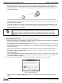
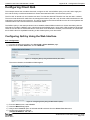
4.) When prompted, enter admin for the user name and admin for the password, then click Logon.
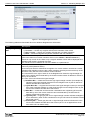
Figure 2 - Web UI Login Prompt
When you first log in, the Basic Settings page for UAP administration is displayed, as the following figure
shows.
March 2012
Unified Access Point Administrator’s Guide
Page 14
Unified Access Point Administrator’s Guide
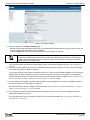
Section 2 - Getting Started
Figure 3 - Provide Basic Settings
5.) Verify the settings on the Basic Settings page.
•)Review access point description and provide a new administrator password for the access point if you do not
want to use the default password, which is admin.
•)Click the Apply button to activate the wireless network with these new settings.
Note: The changes you make are not saved or applied until you click Apply. Changing some
access point settings might cause the AP to stop and restart system processes. If this happens,
wireless clients will temporarily lose connectivity. We recommend that you change access point
settings when WLAN traffic is low.
For information about the fields and configuration options on the Basic Settings page, see “Basic Settings” on
page 16.
6.) If you do not have a DHCP server on the management network and do not plan to use one, you must change
the Connection Type from DHCP to Static IP.
You can either assign a new Static IP address to the AP or continue using the default address. We recommend
assigning a new Static IP address so that if you bring up another UAP on the same network, the IP address
for each AP will be unique. To change the connection type and assign a static IP address, see “Configuring the
Ethernet Settings” on page 18 (CLI) or “Ethernet Settings” on page 35 (Web).
7.) If your network uses VLANs, you might need to configure the management VLAN ID or untagged VLAN ID on
the UAP in order for it to work with your network.
For information about how to configure VLAN information, see “Configuring the Ethernet Settings” on page 18
(CLI) or “Ethernet Settings” on page 35 (Web).
8.) If your network uses IEEE 802.1X port security for network access control, you must configure the 802.1X
supplicant information on the AP.
For information about how to configure the 802.1X user name and password, see “Configuring IEEE 802.1X
Authentication” on page 19.
March 2012
Unified Access Point Administrator’s Guide
Page 15
Unified Access Point Administrator’s Guide
Section 2 - Getting Started
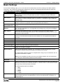
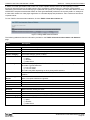
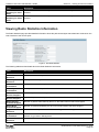
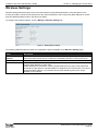
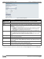
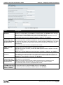
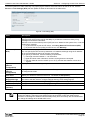
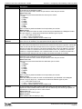
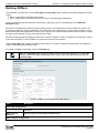
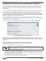
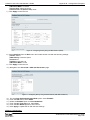
Basic Settings
From the Basic Settings page, you can view various information about the UAP, including IP and MAC address
information, and configure the administrator password for the UAP. The following table describes the fields and
configuration options on the Basic Settings page.
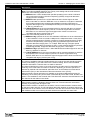
Field
Description
IP Address
Shows the IP address assigned to the AP. This field is not editable on this page because
the IP address is already assigned (either by DHCP, or statically through the Ethernet
Settings page).
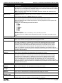
IPv6 Address
Shows the IPv6 address assigned to the AP. This field is not editable on this page because
the IP address is already assigned (either by DHCPv6, or statically through the Ethernet
Settings page).
IPv6 Address Status Shows the operational status of the static IPv6 address assigned to the management
interface of the AP. The possible values are Operational and Tentative.
IPv6 Autoconfigured Shows each automatically-configured global IPv6 address for the management interface of
Global Addresses
the AP.
IPv6 Link Local
Address
Shows the IPv6 Link Local address, which is the IPv6 address used by the local physical
link. The link local address is not configurable and is assigned by using the IPv6 Neighbor
Discovery process.
MAC Address
Shows the MAC address of the AP. The address shown here is the MAC address
associated with the management interface. This is the address by which the AP is known
externally to other networks.
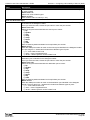
Firmware Version
Shows version information about the firmware currently installed on the AP. As new
versions of the WLAN AP firmware become available, you can upgrade the firmware on
your APs.
Product Identifier
Identifies the AP hardware model.
Hardware Version
Identifies the AP hardware version.
Serial Number
Shows the AP serial number.
Device Name
Generic name to identify the type of hardware.
Device Description
Provides information about the product hardware.
Current Password
Enter the current administrator password. You must correctly enter the current password
before you are able to change it.
New Password
Enter a new administrator password. The characters you enter are displayed as bullet
characters to prevent others from seeing your password as you type.
The administrator password must be an alphanumeric string of up to 8 characters. Do not
use special characters or spaces.
Note: As an immediate first step in securing your wireless network, we recommend that
you change the administrator password from the default.
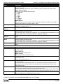
Confirm New
Password
Re-enter the new administrator password to confirm that you typed it as intended.
Baud Rate
Select a baud rate for the serial port connection. The baud rate on the AP must match the
baud rate on the terminal or terminal emulator to connect to the AP command-line interface
(CLI) by using a serial (console) connection.
The following baud rates are available:
•) 9600
•) 19200
•) 38400
•) 57600
•) 115200
System Name
March 2012
Enter a name for the AP. This name appears only on the Basic Settings page and is a
name to identify the AP to the administrator. Use up to 64 alphanumeric characters, for
example My AP.
Unified Access Point Administrator’s Guide
Page 16
Unified Access Point Administrator’s Guide
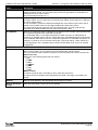
Section 2 - Getting Started
Field
Description
System Contact
Enter the name, e-mail address, or phone number of the person to contact regarding
issues related to the AP.
System Location
Enter the physical location of the AP, for example Conference Room A.
Table 4 - Basic Settings Page
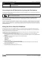
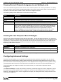
Connecting to the AP Web Interface by Using the IPv6 Address
To connect to the AP by using the IPv6 global address or IPv6 link local address, you must enter the AP address into
your browser in a special format.
Note: The following instructions and examples work with Microsoft Internet Explorer 7 (IE7) and
might not work with other browsers.
To connect to an IPv6 global address, add square brackets around the IPv6 address. For example, if the AP
global IPv6 address is 2520::230:abff:fe00:2420, type the following address into the IE7 address field: http://
[2520::230:abff:fe00:2420].
To connect to the iPv6 link local address, replace the colons (:) with hyphens (-), add the interface number preceded
with an “s,” then add “.ipv6-literal.net.” For example, if the AP link local address is fe80::230:abff:fe00:2420, and the
Windows interface is defined as “%6,” type the following address into the IE7 address field: http://fe80--230-abff-fe002420s6.ipv6-literal.net.
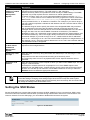
Using the CLI to View the IP Address
The DHCP client on the UAP is enabled by default. If you connect the UAP to a network with a DHCP server, the
AP automatically acquires an IP address. To manage the UAP by using the Administrator UI, you must enter the IP
address of the access point into a Web browser.
If a DHCP server on your network assigns an IP address to the UAP, and you do not know the IP address, use the
following steps to view the IP address of the UAP:
1.) Using a null-modem cable, connect a VT100/ANSI terminal or a workstation to the console (serial) port.
If you attached a PC, Apple, or UNIX workstation, start a terminal-emulation program, such as HyperTerminal or
TeraTerm.
2.) Configure the terminal-emulation program to use the following settings:
•)Baud rate: 115200 bps
•)Data bits: 8
•)Parity: none
•)Stop bit: 1
•)Flow control: none
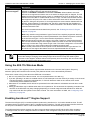
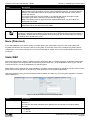
3.) Press the return key, and a login prompt should appear.
The login name is admin. The default password is admin. After a successful login, the screen shows the
(Access Point Name)# prompt.
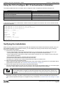
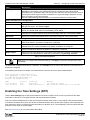
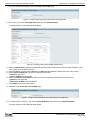
4.) At the login prompt, enter get management.
Information similar to the following prints to the screen.
March 2012
Unified Access Point Administrator’s Guide
Page 17
Unified Access Point Administrator’s Guide
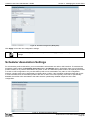
Section 2 - Getting Started
Figure 4 - Command Line Interface (CLI) Connection
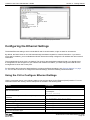
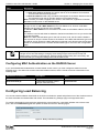
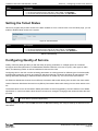
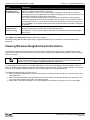
Configuring the Ethernet Settings
The default Ethernet settings, which include DHCP and VLAN information, might not work for all networks.
By default, the DHCP client on the UAP automatically broadcasts requests for network information. If you want to
use a static IP address, you must disable the DHCP client and manually configure the IP address and other network
information.
The management VLAN is VLAN 1 by default. This VLAN is also the default untagged VLAN. If you already have
a management VLAN configured on your network with a different VLAN ID, you must change the VLAN ID of the
management VLAN on the access point.
For information about using the Web interface to configure the Ethernet settings, see “Ethernet Settings” on page
35. You can also use the CLI to configure the Ethernet settings, which the following section describes.
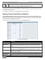
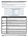
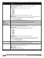
Using the CLI to Configure Ethernet Settings
Use the commands shown in the following table to view and set values for the Ethernet (wired) interface. For more
information about each setting, see the description for the field in the following table.
Action
Commands
Get the DNS Name
get host id
Set the DNS Name
Get Current Settings for the Ethernet (Wired) Internal
Interface
Set the management VLAN ID
View untagged VLAN information
Enable the untagged VLAN
Disable the untagged VLAN
Set the untagged VLAN ID
View the connection type
March 2012
set host id <host_name>
For example:
set host id lab-ap
get management
set management vlan-id <1-4094>
get untagged-vlan
set untagged-vlan status up
set untagged-vlan status down
set untagged-vlan vlan-id <1-4094>
get management dhcp-status
Unified Access Point Administrator’s Guide
Page 18
Unified Access Point Administrator’s Guide
Section 2 - Getting Started
Action
Commands
Use DHCP as the connection type
set management dhcp-status up
set management dhcp-status down
Use a Static IP as the connection type
set management static-ip <ip_address>
Set the Static IP address
For example:
set management static-ip 10.10.12.221
set management static-mask <netmask>
Set a Subnet Mask
For example:
set management static-mask 255.255.255.0
set static-ip-route gateway <ip_address>
Set the Default Gateway
For example:
View the DNS Nameserver mode Dynamic= up
Manual=down
Set DNS Nameservers to Use Static IP Addresses
(Dynamic to Manual Mode)
set static-ip-route gateway 10.10.12.1
get host dns-via-dhcp
set host dns-via-dhcp down
set host static-dns-1 <ip_address>
set host static-dns-2 <ip_address>
For example:
Set DNS Nameservers to Use DHCP IP Addressing
(Manual to Dynamic Mode)
set host static-dns-1 192.168.23.45
set host dns-via-dhcp up
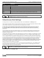
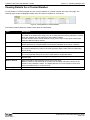
Table 5 - CLI Commands for Ethernet Setting
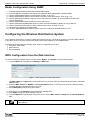
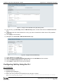
In the following example, the administrator uses the CLI to set the management VLAN ID to 123 and to disable the
untagged VLAN so that all traffic is tagged with a VLAN ID.
DLINK-WLAN-AP# set management vlan-id 123
DLINK-WLAN-AP# set untagged-vlan status down
DLINK-WLAN-AP# get management
Property
Value
-------------------------------------------vlan-id
123
interface
brtrunk
static-ip
10.90.90.91
static-mask
255.0.0.0
ip
10.90.90.91
mask
255.0.0.0
mac
00:05:5E:80:70:00
dhcp-status
down
ipv6-status
up
ipv6-autoconfig-status
up
static-ipv6
::
static-ipv6-prefix-length
0
DLINK-WLAN-AP# get untagged-vlan
Property Value
--------------vlan-id
1
status
down
DLINK-WLAN-AP#
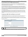
Configuring IEEE 802.1X Authentication
On networks that use IEEE 802.1X, port-based network access control, a supplicant (client) cannot gain access to
the network until the 802.1X authenticator grants access. If your network uses 802.1X, you must configure 802.1X
authentication information that the AP can supply to the authenticator.
If your network uses IEEE 802.1X see “Configuring IEEE 802.1X Authentication” on page 19 for information about
how to configure 802.1X by using the Web interface.
March 2012
Unified Access Point Administrator’s Guide
Page 19
Unified Access Point Administrator’s Guide
Section 2 - Getting Started
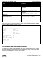
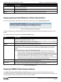
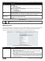
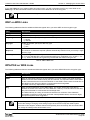
Using the CLI to Configure 802.1X Authentication Information
The following table shows the commands used to configure the 802.1X supplicant information using the CLI.
Action
Command
View 802.1X supplicant settings
get dot1x-supplicant
set dot1x-supplicant status up
Enable 802.1X supplicant
set dot1x-supplicant status down
Disable 802.1X supplicant
set dot1x-supplicant user <name>
Set the 802.1X user name
set dot1x-supplicant password <password>
Set the 802.1X password
Table 6 - CLI Commands for the 802.1X Supplicant
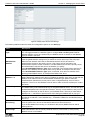
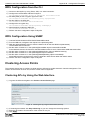
In the following example, the administrator enables the 802.1X supplicant and sets the user name to wlanAP and the
password to test1234.
DLINK-WLAN-AP# set dot1x-supplicant status up
DLINK-WLAN-AP# set dot1x-supplicant user wlanAP
DLINK-WLAN-AP# set dot1x-supplicant password test1234
DLINK-WLAN-AP# get dot1x-supplicant
Property
Value
-------------------------status
up
user
wlanAP
eap-method
md5
debug
off
cert-present
no
cert-exp-date Not Present
DLINK-WLAN-AP#
Verifying the Installation
Make sure the access point is connected to the LAN and associate some wireless clients with the network. Once you
have tested the basics of your wireless network, you can enable more security and fine-tune the AP by modifying
advanced configuration features.
1.) Connect the access point to the LAN.
•)If you configured the access point and administrator PC by connecting both into a network hub, then your
access point is already connected to the LAN. The next step is to test some wireless clients.
•)If you configured the access point by using a direct cable connection from your computer to the access point,
do the following procedures:
•)Disconnect the cable from the computer and the access point.
•)Connect an Ethernet cable from the access point to the LAN.
•)Connect your computer to the LAN by using an Ethernet cable or a wireless card.
2.) Test LAN connectivity with wireless clients.
Test the UAP by trying to detect it and associate with it from some wireless client devices. For information about
requirements for these clients, see “Wireless Client Requirements” on page 12.
3.) Secure and configure the access point by using advanced features.
Once the wireless network is up and you can connect to the AP with some wireless clients, you can add in layers
of security, create multiple virtual access points (VAPs), and configure performance settings.
Note: The WLAN AP is not designed for multiple, simultaneous configuration changes. If more
than one administrator is logged onto the Administration Web pages and making changes to the
configuration, there is no guarantee that all configuration changes specified by multiple users will
be applied.
By default, no security is in place on the access point, so any wireless client can associate with it and access
your LAN. An important next step is to configure security, as described in “Virtual Access Point Settings” on page
47.
March 2012
Unified Access Point Administrator’s Guide
Page 20
Unified Access Point Administrator’s Guide
Section 2 - Getting Started
Configuring Security on the Wireless Access Point
You configure secure wireless client access by configuring security for each virtual access point (VAP) that you
enable. You can configure up to 16 VAPs per radio that simulate multiple APs in one physical access point. By default,
only one VAP is enabled. For each VAP, you can configure a unique security mode to control wireless client access.
Each radio has 16 VAPs, with VAP IDs from 0-15. By default, only VAP 0 on each radio is enabled. VAP0 has the
following default settings:
•) VLAN ID: 1
•) Broadcast SSID: Enabled
•) SSID: dlink1
•) Security: None
•) MAC Authentication Type: None
•) Redirect Mode: None
All other VAPs are disabled by default. The default SSID for VAPs 1–15 is ”dlinkx” where x is the VAP ID.
To prevent unauthorized access to the UAP, we recommend that you select and configure a security option other than
None for the default VAP and for each VAP that you enable.
For information about how to configure the security settings on each VAP, see “Virtual Access Point Settings” on page
47.
March 2012
Unified Access Point Administrator’s Guide
Page 21
Unified Access Point Administrator’s Guide
Section 3 - Viewing Access Point Status
Section 3 - Viewing Access Point Status
This section describes the information you can view from the tabs under the Status heading on the Administration
Web UI. This section contains the following subsections:
•)“Viewing Interface Status” on page 22
•)“Viewing Events” on page 23
•)“Viewing Transmit and Receive Statistics” on page 25
•)“Viewing Associated Wireless Client Information” on page 26
•)“Viewing TSPEC Client Associations” on page 26
•)“Viewing Rogue AP Detection” on page 28
•)“Viewing Managed AP DHCP Information” on page 31
•)“Viewing TSPEC Status and Statistics Information” on page 31
•)“Viewing TSPEC AP Statistics Information” on page 32
•)“Viewing Radio Statistics Information” on page 33
•)“Viewing Email Alert Operational Status” on page 34
Note: The web-based UI images show the DWL-8600AP administration pages. Pages for the
DWL-2600AP or DWL-3600AP will display information for one radio only.
Viewing Interface Status
To monitor Ethernet LAN (wired) and wireless LAN (WLAN) settings, click the Interfaces tab.
Figure 5 - Viewing Interface Status
This page displays the current settings of the UAP. It displays the Wired Settings and the Wireless Settings.
Wired Settings (Internal Interface)
The Internal interface includes the Ethernet MAC Address, Management VLAN ID, IP Address (IPv4 and IPv6),
Subnet Mask, and DNS information. To change any of these settings, click the Edit link. After you click Edit, you are
redirected to the Ethernet Settings page.
For information about configuring these settings, see “Configuring the Ethernet Settings” on page 18.
Wireless Settings
The Radio Interface includes the AeroScout™ Engine Communication status, Radio Mode and Channel. The
Wireless Settings section also shows the MAC address (read-only) associated with each radio interface.
To change the Radio Mode or Channel settings, click the Edit link. After you click Edit, you are redirected to the
March 2012
Unified Access Point Administrator’s Guide
Page 22
Unified Access Point Administrator’s Guide
Section 3 - Viewing Access Point Status
Modify Wireless Settings page.
For information about configuring these settings, see “Wireless Settings” on page 37 and “Modifying Radio Settings”
on page 40.
Viewing Events
The Events page shows real-time system events on the AP such as wireless clients associating with the AP and being
authenticated.
To view system events, click the Events tab.
Figure 6 - Viewing Events
From the Events page, you can perform the following tasks:
•) View the most recent, high-level events generated by this AP.
•) Enable and configure Persistent logging to write system event logs to non-volatile memory so that the events
are not erased when the system reboots.
•) Set a Severity Level to determine what category of log messages are displayed.
•) Set Depth to determine how many log messages are displayed in the Event log.
•) Enable a remote log relay host to capture all system events and errors in a Kernel Log.
Note: The AP acquires its date and time information using the network time protocol (NTP). This
data is reported in UTC format (also known as Greenwich Mean Time). You need to convert the
reported time to your local time.
Configuring Persistent Logging Options
If the system unexpectedly reboots, log messages can be useful to diagnose the cause. However, log messages are
erased when the system reboots unless you enable persistent logging.
Caution! Enabling persistent logging can wear out the flash (non-volatile) memory and degrade
network performance. You should only enable persistent logging to debug a problem. Make sure
you disable persistent logging after you finish debugging the problem.
To configure persistent logging on the Events page, set the persistence, severity, and depth options as described in
the following table, and then click Apply.
March 2012
Unified Access Point Administrator’s Guide
Page 23
Unified Access Point Administrator’s Guide
Section 3 - Viewing Access Point Status
Field
Description
Persistence
Choose Enabled to save system logs to non-volatile memory so that the logs are not erased
when the AP reboots. Choose Disabled to save system logs to volatile memory. Logs in
volatile memory are deleted when the system reboots.
Severity
Specify the severity level of the log messages to write to non-volatile memory. For example,
if you specify 2, critical, alert, and emergency logs are written to non-volatile memory. Error
messages with a severity level of 3 – 7 are written to volatile memory.
•) 0 — emergency
•) 1 — alert
•) 2 — critical
•) 3 — error
•) 4 — warning
•) 5 — notice
•) 6 — info
•) 7 — debug
Depth
You can store up to 128 messages in non-volatile memory. Once the number you configure
in this field is reached, the oldest log event is overwritten by the new log event.
Table 7 - Logging Options
Note: To apply your changes, click Apply. Changing some settings might cause the AP to stop
and restart system processes. If this happens, wireless clients will temporarily lose connectivity.
We recommend that you change AP settings when WLAN traffic is low.
Configuring the Log Relay Host for Kernel Messages
The Kernel Log is a comprehensive list of system events (shown in the System Log) and kernel messages such as
error conditions, like dropping frames.
You cannot view kernel log messages directly from the Administration Web UI for an AP. You must first set up a remote
server running a syslog process and acting as a syslog log relay host on your network. Then, you can configure the
UAP to send syslog messages to the remote server.
Remote log server collection for AP syslog messages provides the following features:
•) Allows aggregation of syslog messages from multiple APs
•) Stores a longer history of messages than kept on a single AP
•) Triggers scripted management operations and alerts
To use Kernel Log relaying, you must configure a remote server to receive the syslog messages. The procedure to
configure a remote log host depends on the type of system you use as the remote host.
Note: The syslog process will default to use port 514. We recommend keeping this default port.
However; If you choose to reconfigure the log port, make sure that the port number you assign to
syslog is not being used by another process.
Enabling or Disabling the Log Relay Host on the Events Page
To enable and configure Log Relaying on the Events page, set the Log Relay options as described in the following
table, and then click Apply.
Field
Description
Relay Log
Select Enabled to allow the UAP to send log messages to a remote host. Select Disabled
to keep all log messages on the local system.
Relay Host
Specify the IP Address or DNS name of the remote log server.
Relay Port
Specify the Port number for the syslog process on the Relay Host.
The default port is 514.
Table 8 - Log Relay Host
March 2012
Unified Access Point Administrator’s Guide
Page 24
Unified Access Point Administrator’s Guide
Section 3 - Viewing Access Point Status
Note: To apply your changes, click Apply. Changing some settings might cause the AP to stop
and restart system processes. If this happens, wireless clients will temporarily lose connectivity.
We recommend that you change AP settings when WLAN traffic is low.
If you enabled the Log Relay Host, clicking Apply will activate remote logging. The AP will send its kernel messages
real-time for display to the remote log server monitor, a specified kernel log file, or other storage, depending on how
you configured the Log Relay Host.
If you disabled the Log Relay Host, clicking Apply will disable remote logging.
Viewing Transmit and Receive Statistics
The Transmit/Receive page provides some basic information about the current AP and a real-time display of the
transmit and receive statistics for the Ethernet interface on the AP and for the VAPs on all supported radio interfaces.
All transmit and receive statistics shown are totals since the AP was last started. If you reboot the AP, these figures
indicate transmit and receive totals since the reboot.
To view transmit and receive statistics for the AP, click the Transmit/Receive page.
Figure 7 - Viewing Traffic Statistics
Field
Description
Interface
The name of the Ethernet or VAP interface.
Status
Shows whether the interface is up or down.
MAC Address
MAC address for the specified interface. The UAP has a unique MAC address for each
interface. Each radio has a different MAC address for each interface on each of its two
radios.
VLAN ID
Virtual LAN (VLAN) ID.
You can use VLANs to establish multiple internal and guest networks on the same AP.
The VLAN ID is set on the VAP page. (See “Configuring Load Balancing” on page 60)
Name (SSID)
Wireless network name. Also known as the SSID, this alphanumeric key uniquely identifies a
wireless local area network.
The SSID is set on the VAP page. (See “Configuring Load Balancing” on page 60)
Transmit and Receive Information
Total Packets
Indicates total packets sent (in Transmit table) or received (in Received table) by this AP.
Total Bytes
Indicates total bytes sent (in Transmit table) or received (in Received table) by this AP.
March 2012
Unified Access Point Administrator’s Guide
Page 25
Unified Access Point Administrator’s Guide
Section 3 - Viewing Access Point Status
Field
Description
Total Drop Packets
Indicates total number of packets sent (in Transmit table) or received (in Received table) by
this AP that were dropped.
Total Drop Bytes
Indicates total number of bytes sent (in Transmit table) or received (in Received table) by
this AP that were dropped.
Errors
Indicates total errors related to sending and receiving data on this AP.
Table 9 - Transmit/Receive
Viewing Associated Wireless Client Information
To view the client stations associated with a particular access point, click the Client Associations tab.
Figure 8 - Viewing Client Association Information
The associated stations are displayed along with information about packet traffic transmitted and received for each
station.
The following describes the fields on the Client Associations page.
Field
Description
Network
Shows which VAP the client is associated with. For example, an entry of wlan0vap2 means
the client is associated with Radio 1, VAP 2.
An entry of wlan0 means the client is associated with VAP 0 on Radio 1. An entry of wlan1
means the client is associated with VAP 0 on Radio 2.
Station
Shows the MAC address of the associated wireless client.
Status
The Authenticated and Associated Status shows the underlying IEEE 802.11 authentication
and association status, which is present no matter which type of security the client uses to
connect to the AP. This status does not show IEEE 802.1X authentication or association
status.
Some points to keep in mind with regard to this field are:
•) If the AP security mode is None or Static WEP, the authentication and association
status of clients showing on the Client Associations page will be in line with what is
expected; that is, if a client shows as authenticated to the AP, it will be able to transmit
and receive data. (This is because Static WEP uses only IEEE 802.11 authentication.)
•) If the AP uses IEEE 802.1X or WPA security, however, it is possible for a client
association to show on this page as authenticated (via the IEEE 802.11 security) but
actually not be authenticated to the AP via the second layer of security.
From Station
Shows the number of packets and bytes received from the wireless client and the number of
packets and bytes that were dropped after being received.
To Station
Shows the number of packets and bytes transmitted from the AP to the wireless client and
the number of packets and bytes that were dropped upon transmission.
Table 10 - Associated Clients
Viewing TSPEC Client Associations
The TSPEC Client Association Status and Statistics page provides some basic information about the client
associations status and a real-time display of the transmit and receive statistics for the TSPEC clients. All transmit and
receive statistics shown are totals since the client association started.
March 2012
Unified Access Point Administrator’s Guide
Page 26
Unified Access Point Administrator’s Guide
Section 3 - Viewing Access Point Status
A TSPEC is a traffic specification that is sent from a QoS-capable wireless client to an AP requesting a certain
amount of network access for the traffic stream (TS) it represents. A traffic stream is a collection of data packets
identified by the wireless client as belonging to a particular user priority. An example of a voice traffic stream is a Wi-Fi
CERTIFIED™ telephone handset that marks its codec-generated data packets as voice priority traffic. An example of
a video traffic stream is a video player application on a wireless laptop that prioritizes a video conference feed from a
corporate server.
To view TSPEC client association statistics, click the TSPEC Client Associations tab.
Figure 9 - Viewing TSPEC Client Associations
The following table describes the information provided on the TSPEC Client Association Status and Statistics
page.
Field
Description
Status
Network
Radio interface used by the client.
Station
Client station MAC address.
TS Identifier
TSPEC Traffic Session Identifier (range 0-7).
Access Category
TS Access Category (voice or video).
Direction
The traffic direction for this TS. Direction can be:
•) uplink
•) downlink
•) bidirectional
User Priority
The User Priority (UP) for this TS. The UP is sent with each packet in the UP portion of the
IP header. Typical values are:
•) 6 or 7 for voice
•) 4 or 5 for video
The value may differ depending on other priority traffic sessions.
Medium Time
The time (in 32 microsecond per second units) that the TS traffic occupies the transmission
medium.
Excess Usage
Events
The number of times the client has exceeded the medium time established for its TSPEC.
Minor, infrequent violations are ignored.
VAP
The Virtual Access Point associated with this TS client.
MAC Address
The Virtual Access Point MAC address.
SSID
The service set identifier associated with this TS client.
Statistics
Network
Radio interface used by the client.
Station
Client station MAC address.
TS Identifier
TSPEC Traffic Session Identifier (range 0-7).
Access Category
TS Access Category (voice or video).
Direction
The traffic direction for this TS. Direction can be:
•) uplink
•) downlink
•) bidirectional
March 2012
Unified Access Point Administrator’s Guide
Page 27
Unified Access Point Administrator’s Guide
Section 3 - Viewing Access Point Status
Field
Description
From Station
Shows the number of packets and bytes received from the wireless client and the number
of packets and bytes that were dropped after being received. Also shows the number of
packets:
•) in excess of an admitted TSPEC.
•) for which no TSPEC has been established when admission is required by the AP.
To Station
Shows the number of packets and bytes transmitted from the AP to the wireless client and
the number of packets and bytes that were dropped upon transmission. Also shows the
number of packets:
•) in excess of an admitted TSPEC.
•) for which no TSPEC has been established when admission is required by the AP.
Table 11 - TSPEC Client Associations
Link Integrity Monitoring
The UAP provides link integrity monitoring to continually verify its connection to each associated client. To do this,
the AP sends data packets to clients every few seconds when no other traffic is passing. This allows the AP to detect
when a client goes out of range, even during periods when no normal traffic is exchanged. The client connection
drops off the list within 300 seconds if these data packets are not acknowledged, even if no disassociation message is
received.
Viewing Rogue AP Detection
The status page to view Rogue AP Detection information provides real-time statistics for all APs within range of the
AP on which you are viewing the Administration Web pages. When AP detection is enabled, the radio will periodically
switch from its operating channel to scan other channels within the same band. Click Refresh to update the screen
and display the most current information.
The Rogue AP Detection page contains the following two lists:
•) Detected Rogue AP List — Lists all APs within range of the AP that have not been acknowledged as known APs.
•) Known AP List — Lists all APs within range of the AP that have been acknowledged as known APs either by
clicking the Grant button associated with an AP in the Detected Rogue AP List or by appearing in an imported
AP list.
To view information about other access points on the wireless network, click the Rogue AP Detection tab.
Figure 10 - Viewing Rogue and Known Access Points
You must enable the AP detection on a radio in order to collect information about other APs within range.
The following table describes the information provided on neighboring access points.
March 2012
Unified Access Point Administrator’s Guide
Page 28
Unified Access Point Administrator’s Guide
Section 3 - Viewing Access Point Status
Field
Description
AP Detection for
Radio
To allow the AP radios to perform neighbor AP detection and collect information about
neighbor APs, click Enabled.
To disable neighbor AP detection on the radios, click Disabled.
If you change the AP detection mode, click Apply to save the new settings.
Detected Rogue AP List
Action
Click Grant to move the AP from the Detected Rogue AP List to the Known AP List.
Note: The Detected Rouge AP and Known AP lists provide information. The DWL-x600AP
does not have any control over the APs on the list and cannot apply any security policies to
APs detected through the RF scan.
MAC
Shows the MAC address of the neighboring AP.
Radio
The Radio field indicates which radio detected the neighboring AP:
•) wlan0 (Radio One)
•) wlan1 (Radio Two)
Beacon Int.
Shows the Beacon interval being used by this AP.
Beacon frames are transmitted by an AP at regular intervals to announce the existence
of the wireless network. The default behavior is to send a beacon frame once every 100
milliseconds (or 10 per second).
The Beacon Interval is set on the Radio page.(See “Modifying Radio Settings” on page
40)
Type
Indicates the type of device:
•) AP indicates the neighboring device is an AP that supports the IEEE 802.11 Wireless
Networking Framework in Infrastructure Mode.
•) Ad hoc indicates a neighboring station running in Ad hoc Mode. Stations set to ad
hoc mode communicate with each other directly, without the use of a traditional AP.
Ad-hoc mode is an IEEE 802.11 Wireless Networking Framework also referred to as
peer-to-peer mode or an Independent Basic Service Set (IBSS).
SSID
The Service Set Identifier (SSID) for the AP.
The SSID is an alphanumeric string of up to 32 characters that uniquely identifies a wireless
local area network. It is also referred to as the Network Name.
The SSID is set on the VAP page. (See “Configuring Load Balancing” on page 60)
Privacy
Indicates whether there is any security on the neighboring device.
•) Off indicates that the Security mode on the neighboring device is set to None (no
security).
•) On indicates that the neighboring device has some security in place.
•) Security is configured on the AP from the VAP page.
WPA
Indicates whether WPA security is on or off for this AP.
Band
This indicates the IEEE 802.11 mode being used on this AP. (For example, IEEE 802.11a,
IEEE 802.11b, IEEE 802.11g.)
The number shown indicates the mode according to the following map:
•) 2.4 indicates IEEE 802.11b, 802.11g, or 802.11n mode (or a combination of the modes)
•) 5 indicates IEEE 802.11a or 802.11n mode (or both modes)
Channel
Shows the Channel on which the AP is currently broadcasting.
The channel defines the portion of the radio spectrum that the radio uses for transmitting
and receiving.
The channel is set in Radio Settings. (See “Modifying Radio Settings” on page 40)
Rate
Shows the rate (in megabits per second) at which this AP is currently transmitting.
The current rate will always be one of the rates shown in Supported Rates.
Signal
Indicates the strength of the radio signal emitting from this AP. If you hover the mouse
pointer over the bars, a number appears and shows the strength in decibels (dB).
Beacons
Shows the total number of beacons received from this AP since it was first discovered.
Last Beacon
Shows the date and time of the last beacon received from this AP.
Rates
Shows supported and basic (advertised) rate sets for the neighboring AP. Rates are shown
in megabits per second (Mbps).
All Supported Rates are listed, with Basic Rates shown in bold.
Rate sets are configured on the Radio Settings page. (See “Modifying Radio Settings” on
page 40)
March 2012
Unified Access Point Administrator’s Guide
Page 29
Unified Access Point Administrator’s Guide
Field
Section 3 - Viewing Access Point Status
Description
Known AP List
Action
An AP can appear in the Known AP List if it has been moved from the Detected Rogue AP
List by clicking the Grant button or if the MAC address of the AP appears in an AP list that
has been imported.
To move the AP from the Known AP List to the Detected Rogue AP List, click Delete.
Note: The Detected Rouge AP and Known AP lists provide information. The DWL-x600AP
does not have any control over the APs on the list and cannot apply any security policies to
APs detected through the RF scan.
MAC
Shows the MAC address of the neighboring AP.
Type
Indicates the type of device:
•) AP indicates the neighboring device is an AP that supports the IEEE 802.11 Wireless
Networking Framework in Infrastructure Mode.
•) Ad hoc indicates a neighboring station running in Ad hoc Mode. Stations set to ad
hoc mode communicate with each other directly, without the use of a traditional AP.
Ad-hoc mode is an IEEE 802.11 Wireless Networking Framework also referred to as
peer-to-peer mode or an Independent Basic Service Set (IBSS).
SSID
The Service Set Identifier (SSID) for the AP.
The SSID is an alphanumeric string of up to 32 characters that uniquely identifies a wireless
local area network. It is also referred to as the Network Name.
The SSID is set on the VAP page. (See “Configuring Load Balancing” on page 60)
Privacy
Indicates whether there is any security on the neighboring device.
•) Off indicates that the Security mode on the neighboring device is set to None (no
security).
•) On indicates that the neighboring device has some security in place.
•) Security is configured on the AP from the VAP page.
Band
This indicates the IEEE 802.11 mode being used on this AP. (For example, IEEE 802.11a,
IEEE 802.11b, IEEE 802.11g.)
The number shown indicates the mode according to the following map:
•) 2.4 indicates IEEE 802.11b, 802.11g, or 802.11n mode (or a combination of the modes)
•) 5 indicates IEEE 802.11a or 802.11n mode (or both modes)
Channel
Shows the Channel on which the AP is currently broadcasting.
The channel defines the portion of the radio spectrum that the radio uses for transmitting
and receiving.
The channel is set in Radio Settings. (See “Modifying Radio Settings” on page 40)
Table 12 - Rogue AP Detection
Saving and Importing the Known AP List
To save the Known AP list to a file, click Save. The list contains the MAC addresses of all AP that have been added to
the Known AP List. By default, the filename is Rogue1.cfg. You can use a text editor or Web browser to open the file
and view its contents.
Use the Import feature to import a list of Known APs from a saved list. The list might be from another DWL-x600AP or
created from a text file. If the MAC address of an AP appears in the Known AP List, it will not be detected as a rogue.
To import an AP List from a file, use the following steps:
1.) Choose whether to replace the existing Known AP list or add the entries in the imported file to the Known AP list.
•)Select the Replace option to import the list and replace the contents of the Known AP List.
•)Select the Merge option to import the list and add the APs in the imported file to the APs currently displayed in
the Known AP List.
2.) Click Browse and choose the file to import.
•)The file you import must be a plain-text file with a .txt or .cfg extension. Entries in the file are MAC addresses
in hexadecimal format with each octet separated by colons, for example 00:11:22:33:44:55. Separate entries
with a single space. For the AP to accept the file, it must contain only MAC addresses.
3.) Click Import.
•)Once the import is complete, the screen refreshes and the MAC addresses of the APs in the imported file
March 2012
Unified Access Point Administrator’s Guide
Page 30
Unified Access Point Administrator’s Guide
Section 3 - Viewing Access Point Status
appear in the Known AP List.
Viewing Managed AP DHCP Information
The UAP can learn about D-Link Unified Wireless Switches on the network through DHCP responses to its initial
DHCP request. The Managed AP DHCP page displays the DNS names or IP addresses of up to four D-Link Unified
Wireless Switches that the AP learned about from a DHCP server on your network.
Figure 11 - Managed AP DHCP Information
For information about how to configure a DHCP server to respond to AP DHCP requests with the switch IP address
information, see the User Manual for the switch.
Viewing TSPEC Status and Statistics Information
The TSPEC Status and Statistics page provides:
•) Summary information about TSPEC sessions by radio
•) Summary information about TSPEC sessions by VAP
•) Real-time transmit and receive statistics for the TSPEC VAPs on all radio interfaces.
All of the transmit and receive statistics shown are totals since the AP was last started. If you reboot the AP, these
figures indicate transmit and receive totals since the reboot.
To view TSPEC status and statistics, click the TSPEC Status and Statistics tab.
Figure 12 - Viewing TSPEC Status and Statistics
The following table describes the information provided on TSPEC Status and Statistics page.
March 2012
Unified Access Point Administrator’s Guide
Page 31
Unified Access Point Administrator’s Guide
Field
Section 3 - Viewing Access Point Status
Description
AP and VAP Status
Interface
Indicates the name of the Radio or VAP interface.
Access Category
Indicates Current Access Category associated with this Traffic Stream (voice or video).
Status
Indicates whether the TSPEC session is enabled (up) or not (down) for the corresponding
Access Category.
Note: This is a configuration status (does not necessarily represent the current session
activity).
Active TS
Indicates the number of currently active TSPEC Traffic Streams for this radio and Access
Category.
TS Clients
Indicates the number of Traffic Stream clients associated with this radio and Access
Category.
Medium Time
Admitted
Time (in 32 microsecond per second units) allocated for this Access Category over the
transmission medium to carry data. This value should be less than or equal to the maximum
bandwidth allowed over the medium for this TS.
Medium Time
Unallocated
Time (in 32 microsecond per second units) of unused bandwidth for this Access Category.
Transmit and Receive Statistics
Total Packets
Indicates the total number of TS packets sent (in Transmit table) or received (in Received
table) by this Radio for the specified Access Category.
Total Bytes
Indicates the total number of TS bytes sent (in Transmit table) or received (in Received
table) by this Radio for the specified Access Category.
Total Voice Packets
Indicates the total number of TS voice packets sent (in Transmit table) or received (in
Received table) by this AP for this VAP.
Total Voice Bytes
Indicates the total TS voice bytes sent (in Transmit table) or received (in Received table) by
this AP for this VAP.
Total Video Packets
Indicates the total number of TS video packets sent (in Transmit table) or received (in
Received table) by this AP for this VAP.
Total Video Bytes
Indicates the total TS video bytes sent (in Transmit table) or received (in Received table) by
this AP for this VAP.
Table 13 - TSPEC Status and Statistics
Viewing TSPEC AP Statistics Information
The View TSPEC AP Statistics page provides information on the voice and video Traffic Streams accepted and
rejected by the AP.
To view TSPEC AP statistics, click the TSPEC AP Statistics tab.
Figure 13 - View TSPEC Status and Statistics
The following table describes the information provided on TSPEC AP Statistics page.
March 2012
Unified Access Point Administrator’s Guide
Page 32
Unified Access Point Administrator’s Guide
Section 3 - Viewing Access Point Status
Field
Description
TSPEC Statistics
Summary for Voice
ACM
Indicates the total number of accepted and the total number of rejected voice Traffic
Streams.
TSPEC Statistics
Summary for Video
ACM
Indicates the total number of accepted and the total number of rejected video Traffic
Streams.
Table 14 - TSPEC AP Statistics
Viewing Radio Statistics Information
The Radio Statistics page provides detailed information about the packets and bytes transmitted and received on the
radio interface of this access point.
Figure 14 - View Radio Statistics
The following table describes details about the Radio Statistics information.
Field
Description
Radio
Choose either radio 1 or radio 2 to view statistics for the selected radio
WLAN Packets
Received
Total packets received by the AP on this radio interface.
WLAN Bytes
Received
Total bytes received by the AP on this radio interface.
WLAN Packets
Transmitted
Total packets transmitted by the AP on this radio interface.
WLAN Bytes
Transmitted
Total bytes transmitted by the AP on this radio interface.
WLAN Packets
Receive Dropped
Number of packets received by the AP on this radio interface that were dropped.
WLAN Bytes
Receive Dropped
Number of bytes received by the AP on this radio interface that were dropped.
WLAN Packets
Transmit Dropped
Number of packets transmitted by the AP on this radio interface that were dropped.
WLAN Bytes
Transmit Dropped
Number of bytes transmitted by the AP on this radio interface that were dropped.
Fragments
Received
Count of successfully received MPDU frames of type data or management.
Fragments
Transmitted
Number of transmitted MPDU with an individual address or an MPDU with a multicast
address of type Data or Management.
Multicast Frames
Received
Count of MSDU frames received with the multicast bit set in the destination MAC address.
March 2012
Unified Access Point Administrator’s Guide
Page 33
Unified Access Point Administrator’s Guide
Section 3 - Viewing Access Point Status
Field
Description
Multicast Frames
Transmitted
Count of successfully transmitted MSDU frames where the multicast bit is set in the
destination MAC address.
Duplicate Frame
Count
Number of times a frame is received and the Sequence Control field indicates is a duplicate.
Failed Transmit
Count
Number of times an MSDU is not transmitted successfully due to transmit attempts
exceeding either the short retry limit or the long retry limit.
Transmit Retry
Count
Number of times an MSDU is successfully transmitted after one or more retries.
Multiple Retry
Count
Number of times an MSDU is successfully transmitted after more than one retry.
RTS Success Count
Count of CTS frames received in response to an RTS frame.
RTS Failure Count
Count of CTS frames not received in response to an RTS frame.
ACK Failure Count
Count of ACK frames not received when expected.
FCS Error Count
Count of FCS errors detected in a received MPDU frame.
Frames Transmitted
Count of each successfully transmitted MSDU.
WEP Undecryptable
Count
Count of encrypted frames received and the key configuration of the transmitter indicates
that the frame should not have been encrypted or that frame was discarded due to the
receiving station not implementing the privacy option.
Table 15 - Radio Statistics Information
Viewing Email Alert Operational Status
The Email Alert Operational Status page provides information about the email alerts sent based on the syslog
messages generated in the AP.
To view the Email Alert Operational Status, click the Status > Email Alert Status tab.
To configure the email alerts, see “Configuring Email Alert” on page 72.
Figure 15 - Email Alert Operational Status
The following table describes details about the Email Alert Operational Status.
Field
Description
Email Alert Status
The Email Alert operational status The status is either Up or Down. The default is Down.
Number of Email
Sent
The total number of email sent so far. The range is an unsigned integer of 32 bits. The
default is 0.
Number of Email
Failed
The total number of email failures so far. The range is an unsigned integer of 32 bits. The
default is 0.
Time Since Last
Email Sent
The time since the last email was sent. Time format is used. The default is 00 days 00 hours
00 minutes 00 seconds.
Table 16 - Email Alert Status
March 2012
Unified Access Point Administrator’s Guide
Page 34
Unified Access Point Administrator’s Guide
Section 4 - Managing the Access Point
Section 4 - Managing the Access Point
This section describes how to manage the UAP and contains the following subsections:
•)“Ethernet Settings” on page 35
•)“Wireless Settings” on page 37
•)“Modifying Radio Settings” on page 40
•)“Configuring Radio and VAP Scheduler” on page 44
•)“Scheduler Association Settings” on page 46
•)“Virtual Access Point Settings” on page 47
•)“Configuring the Wireless Distribution System (WDS)” on page 56
•)“Controlling Access by MAC Authentication” on page 59
•)“Configuring Load Balancing” on page 60
•)“” on page 61
•)“Configuring 802.1X Authentication” on page 63
•)“Creating a Management Access Control List (ACL)” on page 64
The configuration pages for the features in this section are located under the Manage heading on the Administration
Web UI.
Ethernet Settings
The default wired interface settings, which include DHCP and VLAN information, might not work for all networks.
By default, the DHCP client on the UAP automatically broadcasts requests for network information. If you want to
use a static IP address, you must disable the DHCP client and manually configure the IP address and other network
information.
The management VLAN is VLAN 1 by default. This VLAN is also the default untagged VLAN. If you already have
a management VLAN configured on your network with a different VLAN ID, you must change the VLAN ID of the
management VLAN on the AP.
To configure the LAN settings, click the Ethernet Settings tab.
Figure 16 - Modify Ethernet (Wired) settings
The following table describes the fields to view or configure on the Ethernet Settings page.
March 2012
Unified Access Point Administrator’s Guide
Page 35
Unified Access Point Administrator’s Guide
Section 4 - Managing the Access Point
Field
Description
Hostname
Enter a hostname for the AP. The hostname appears in the CLI prompt.
•) The hostname has the following requirements:
•) The length must be between 1 – 63 characters.
•) Upper and lower case characters, numbers, and hyphens are accepted.
•) The first character must be a letter (a – z or A – Z), and the last character cannot be a
hyphen.
MAC Address
Shows the MAC address for the LAN interface for the Ethernet port on this AP. This is a
read-only field that you cannot change.
Management VLAN
ID
The management VLAN is the VLAN associated with the IP address you use to access the
AP. The default management VLAN ID is 1.
Provide a number between 1 and 4094 for the management VLAN ID.
Untagged VLAN
If you disable the untagged VLAN, all traffic is tagged with a VLAN ID.
By default all traffic on the UAP uses VLAN 1, which is the default untagged VLAN. This
means that all traffic is untagged until you disable the untagged VLAN, change the untagged
traffic VLAN ID, or change the VLAN ID for a VAP or client using RADIUS.
Untagged VLAN ID
Provide a number between 1 and 4094 for the untagged VLAN ID. Traffic on the VLAN that
you specify in this field will not be tagged with a VLAN ID.
Connection Type
If you select DHCP, the UAP acquires its IP address, subnet mask, DNS, and gateway
information from a DHCP server.
If you select Static IP, you must enter information in the Static IP Address, Subnet Mask,
and Default Gateway fields.
Static IP Address
Enter the static IP address in the text boxes. This field is disabled if you use DHCP as the
connection type.
Subnet Mask
Enter the Subnet Mask in the text boxes.
Default Gateway
Enter the Default Gateway in the text boxes.
DNS Nameservers
Select the mode for the DNS.
In Dynamic mode, the IP addresses for the DNS servers are assigned automatically via
DHCP. This option is only available if you specified DHCP for the Connection Type.
In Manual mode, you must assign static IP addresses to resolve domain names.
IPv6 Admin Mode
Enable or disable IPv6 management access to the AP
IPv6 Auto Config
Admin Mode
Enable or disable IPv6 auto address configuration on the AP.
When IPv6 Auto Config Mode is enabled, automatic IPv6 address configuration and gateway
configuration is allowed by processing the Router Advertisements received on the LAN port.
The AP can have multiple auto configured IPv6 addresses.
Static IPv6 Address
Enter a static IPv6 address. The AP can have a static IPv6 address even if addresses have
already been configured automatically.
Static IPv6 Address
Prefix Length
Enter the static IPv6 prefix length, which is an integer in the range of 0 – 128.
IPv6 Autoconfigured If the AP has been assigned one or more IPv6 addresses automatically, the addresses are
Global Addresses
listed.
IPv6 Link Local
Address
Shows the IPv6 Link Local address, which is the IPv6 address used by the local physical
link. The link local address is not configurable and is assigned by using the IPv6 Neighbor
Discovery process.
Default IPv6
Gateway
Enter the default IPv6 gateway.
Table 17 - Ethernet Settings
Note: After you configure the wired settings, you must click Apply to apply the changes and
to save the settings. Changing some settings might cause the AP to stop and restart system
processes. If this happens, wireless clients will temporarily lose connectivity. We recommend that
you change AP settings when WLAN traffic is low.
March 2012
Unified Access Point Administrator’s Guide
Page 36
Unified Access Point Administrator’s Guide
Section 4 - Managing the Access Point
Wireless Settings
Wireless settings describe aspects of the local area network (LAN) related specifically to the radio device in the
access point (802.11 Mode and Channel) and to the network interface to the access point (MAC address for access
point and Wireless Network name, also known as SSID).
To configure the wireless interface, click the Manage > Wireless Settings tab.
Figure 17 - Modify Wireless Settings
The following table describes the fields and configuration options available on the Wireless Settings page.
Field
Description
TSPEC Violation
Interval
Specify the time interval (in seconds) for the AP to report (through the system log and SNMP
traps) associated clients that do not adhere to mandatory admission control procedures.
Radio Interface
Specify whether you want the radio interface on or off.
MAC Address
Indicates the Media Access Control (MAC) addresses for the interface. Dual-radio APs have
a unique MAC address for each radio.
A MAC address is a permanent, unique hardware address for any device that represents
an interface to the network. The MAC address is assigned by the manufacturer. You cannot
change the MAC address. It is provided here for informational purposes as a unique
identifier for an interface.
March 2012
Unified Access Point Administrator’s Guide
Page 37
Unified Access Point Administrator’s Guide
Section 4 - Managing the Access Point
Field
Description
Mode
The Mode defines the Physical Layer (PHY) standard the radio uses.
Note: The modes available depend on the country code setting and the radio selected.
Select one of the following modes for radio 1:
•) IEEE 802.11a is a PHY standard that specifies operating in the 5 GHz U-NII band
using orthogonal frequency division multiplexing (OFDM). It supports data rates
ranging from 6 to 54 Mbps.
•) IEEE 802.11a/n operates in the 5 GHz ISM band and includes support for both
802.11a and 802.11n devices. IEEE 802.11n is an extension of the 802.11 standard
that includes multiple-input multiple-output (MIMO) technology. IEEE 802.11n
supports data ranges of up to 248 Mbps and nearly twice the indoor range of 802.11
b, 802.11g, and 802.11a.
•) 5 GHz IEEE 802.11n is the recommended mode for networks with 802.11n devices
that operate in the 5 GHz frequency that do not need to support 802.11a devices.
IEEE 802.11n can achieve a higher throughput when it does not need to be
compatible with legacy devices (802.11a).
Select one of the following modes for radio 2:
•) IEEE 802.11b/g operates in the 2.4 GHz ISM band. IEEE 802.11b is an enhancement
of the initial 802.11 PHY to include 5.5 Mbps and 11 Mbps data rates. It uses direct
sequence spread spectrum (DSSS) or frequency hopping spread spectrum (FHSS)
as well as complementary code keying (CCK) to provide the higher data rates. It
supports data rates ranging from 1 to 11 Mbps. IEEE 802.11g is a higher speed
extension (up to 54 Mbps) to the 802.11b PHY. It uses orthogonal frequency division
multiplexing (OFDM). It supports data rates ranging from 1 to 54 Mbps.
•) IEEE 802.11b/g/n operates in the 2.4 GHz ISM band and includes support for 802.11b,
802.11g, and 802.11n devices.
•) 2.4 GHz IEEE 802.11n is the recommended mode for networks with 802.11n devices
that operate in the 2.4 GHz frequency that do not need to support 802.11b/g
devices. IEEE 802.11n can achieve a higher throughput when it does not need to be
compatible with legacy devices (802.11b/g).
Channel
Select the Channel.
The range of available channels is determined by the mode of the radio interface and the
country code setting. If you select Auto for the channel setting, the AP scans available
channels and selects a channel where no traffic is detected.
The Channel defines the portion of the radio spectrum the radio uses for transmitting and
receiving. Each mode offers a number of channels, depending on how the spectrum is
licensed by national and transnational authorities such as the Federal Communications
Commission (FCC) or the International Telecommunication Union (ITU-R).
When automatic channel assignment is enabled on the Channel Management page for
Clustering, the channel policy for the radio is automatically set to static mode, and the Auto
option is not available for the Channel field. This allows the automatic channel feature to set
the channels for the radios in the cluster.
Station Isolation
To enable Station Isolation, select the check box directly beside it.
When Station Isolation is disabled, wireless clients can communicate with one another
normally by sending traffic through the AP.
When Station Isolation is enabled, the AP blocks communication between wireless clients
on the same radio and VAP. The AP still allows data traffic between its wireless clients and
wired devices on the network, across a WDS link, and with other wireless clients associated
with a different VAP, but not among wireless clients associated with the same VAP.
March 2012
Unified Access Point Administrator’s Guide
Page 38
Unified Access Point Administrator’s Guide
Field
Section 4 - Managing the Access Point
Description
AeroScout™ Engine AeroScout Engine support provides location-based services for wireless networks. Specify
Protocol Support
whether to enable support for the AeroScout protocol.
Options are Enabled or Disabled. The default is Disabled. When enabled, Aeroscout
devices are recognized and data is sent to an Aeroscout Engine (AE) for analysis. The AE
determines the geographical location of 802.11 capable devices, such as STAs, APs, and
AeroScout’s line of 802.11 enabled RFID devices, or tags. The AE communicates with APs
that support the AE protocol in order to collect information about the RF devices detected
by the APs. Using the AE protocol, D-Link supports direct communication between AE and
the APs. When operating in managed mode, the AE is configured with the IP address of
the managed access points from which it collects information. The Wireless Switch cannot
communicate with the AE.
For more information about the AeroScout protocol, see “Enabling AeroScout™ Engine
Support” on page 39.
Note: Only AeroScout tag hardware of types T2 and T3 are explicitly supported. Other tag
models are also supported only if their implementation of the AeroScout protocol conforms
to the AeroScout Engine - Access Point Interface Specification, version 2.1.
Note: AeroScout tags operate only in 802.11 b/g mode. Therefore, network administrators
who use the AeroScout tags must configure at least one radio on APs that are expected to
detect tags in either 802.11b/g or 802.11b/g/n mode. The radios configured in 2.4 GHz IEEE
802.11 mode or any of the 5GHz modes cannot detect AeroScout tags.
Note: The AE protocol allows access points to mark detected APs as rogue devices. The
D-Link APs do not support this feature and never report detected APs as rogues.
Table 18 - Wireless Settings
Note: After you configure the wireless settings, you must click Apply to apply the changes and
to save the settings. Changing some settings might cause the AP to stop and restart system
processes. If this happens, wireless clients will temporarily lose connectivity. We recommend that
you change AP settings when WLAN traffic is low.
Using the 802.11h Wireless Mode
For 802.11a radios, if the regulatory domain requires radar detection on the channel, the Dynamic Frequency
Selection (DFS) and Transmit Power Control (TPC) features of 802.11h are automatically activated.
There are a number of key points about the IEEE 802.11h standard:
•) 802.11h only works for the 802.11a band. It is not required for 802.11b or 802.11g.
•) If you are operating in an 802.11h enabled domain, the AP attempts to use the channel you assign. If the channel
has been blocked by a previous radar detection, or if the AP detects a radar on the channel, then the AP
automatically selects a different channel.
•) When 802.11h is enabled, the AP will not be operational in the 5GHz band for at least 60 seconds due to radar
scanning.
•) Setting up WDS links may be difficult when 802.11h is operational. This is because the operating channels of the
two APs on the WDS link may keep changing depending on channel usage and radar interference. WDS will
only work if both the APs operate on the same channel. For more information on WDS, see “Configuring Load
Balancing” on page 60.
Enabling AeroScout™ Engine Support
The AeroScout Engine (AE) is a software platform produced by AeroScout Inc. for location-based services. The AE
can determine the physical location of 802.11 capable AeroScout devices. The AE communicates with APs that have
the AE protocol enabled in order to collect information about the RF devices detected by the APs.
The DWS-4000 Series switch supports only direct communication between the AE and the APs. When operating
in managed mode, the AE is configured with the IP address of the managed access points from which it collects
March 2012
Unified Access Point Administrator’s Guide
Page 39
Unified Access Point Administrator’s Guide
Section 4 - Managing the Access Point
information. The DWS-4000 Series switch does not communicate with the AE.
AeroScout tags operate only in 802.11b/g mode. Therefore, network administrators who use the AeroScout tags must
configure at least one radio on APs that are expected to detect tags in either 802.11b/g or 802.11b/g/n mode. The
radios configured in 2.4 GHz IEEE 802.11n mode cannot detect AeroScout tags.
Note: The following notes apply to AeroScout product and protocol support:
•) D-Link does not sell AeroScout products. Contact AeroScout for AeroScout hardware,
software or deployment information.
•) The AE protocol does not support any authentication or encryption between the AE server
and the access point.
•) The AE protocol requires radios to operate in promiscuous mode. This means that the AP
receives and processes all packets detected by the radios, as opposed to processing only
packets destined to the APs BSSID. This can affect AP throughput.
Modifying Radio Settings
Radio settings directly control the behavior of the radio devices in the AP and its interaction with the physical medium;
that is, how and what type of electromagnetic waves the AP emits.
To specify radio settings, click the Radio tab in the Manage section.
Different settings display depending on the mode you select. All settings are described in the table below.
Figure 18 - Modify Radio Settings
The following table describes the fields and configuration options for the Radio Settings page.
Field
Description
Radio
Select Radio 1or Radio 2 to specify which radio to configure. The rest of the settings on this
page apply to the radio you select in this field. Be sure to configure settings for both radios.
Radio 1 operates in the 5 GHz band (802.11a/n), and Radio 2 operates in the 2.4 GHz band
(802.11b/g/n).
Status (On/Off)
Specify whether you want the radio on or off by clicking On or Off.
If you turn off a radio, the AP sends disassociation frames to all the wireless clients it is
currently supporting so that the radio can be gracefully shutdown and the clients can start
the association process with other available APs.
March 2012
Unified Access Point Administrator’s Guide
Page 40
Unified Access Point Administrator’s Guide
Section 4 - Managing the Access Point
Field
Description
Mode
The Mode defines the Physical Layer (PHY) standard the radio uses.
Note: The modes available depend on the country code setting and the radio selected.
Select one of the following modes for radio 1:
•) IEEE 802.11a is a PHY standard that specifies operating in the 5 GHz U-NII band
using orthogonal frequency division multiplexing (OFDM). It supports data rates
ranging from 6 to 54 Mbps.
•) IEEE 802.11a/n operates in the 5 GHz ISM band and includes support for both
802.11a and 802.11n devices. IEEE 802.11n is an extension of the 802.11 standard
that includes multiple-input multiple-output (MIMO) technology. IEEE 802.11n
supports data ranges of up to 248 Mbps and nearly twice the indoor range of 802.11
b, 802.11g, and 802.11a.
•) 5 GHz IEEE 802.11n is the recommended mode for networks with 802.11n devices
that operate in the 5 GHz frequency that do not need to support 802.11a devices.
IEEE 802.11n can achieve a higher throughput when it does not need to be
compatible with legacy devices (802.11a).
Select one of the following modes for radio 2:
•) IEEE 802.11b/g operates in the 2.4 GHz ISM band. IEEE 802.11b is an enhancement
of the initial 802.11 PHY to include 5.5 Mbps and 11 Mbps data rates. It uses direct
sequence spread spectrum (DSSS) or frequency hopping spread spectrum (FHSS)
as well as complementary code keying (CCK) to provide the higher data rates. It
supports data rates ranging from 1 to 11 Mbps. IEEE 802.11g is a higher speed
extension (up to 54 Mbps) to the 802.11b PHY. It uses orthogonal frequency division
multiplexing (OFDM). It supports data rates ranging from 1 to 54 Mbps.
•) IEEE 802.11b/g/n operates in the 2.4 GHz ISM band and includes support for 802.11b,
802.11g, and 802.11n devices.
•) 2.4 GHz IEEE 802.11n is the recommended mode for networks with 802.11n devices
that operate in the 2.4 GHz frequency that do not need to support 802.11b/g
devices. IEEE 802.11n can achieve a higher throughput when it does not need to be
compatible with legacy devices (802.11b/g).
Channel
Select the Channel.
The range of available channels is determined by the mode of the radio interface and the
country code setting. If you select Auto for the channel setting, the AP scans available
channels and selects a channel where no traffic is detected.
The channel defines the portion of the radio spectrum the radio uses for transmitting and
receiving. Each mode offers a number of channels, depending on how the spectrum is
licensed by national and transnational authorities such as the Federal Communications
Commission (FCC) or the International Telecommunication Union (ITU-R).
When automatic channel assignment is enabled on the Channel Management page for
Clustering, the channel policy for the radio is automatically set to static mode, and the Auto
option is not available for the Channel field. This allows the automatic channel feature to set
the channels for the radios in the cluster.
Channel Bandwidth
(802.11n modes
only)
The 802.11n specification allows a 40 MHz wide channel in addition to the legacy 20 MHz
channel available with other modes. The 40 MHz channel enables higher data rates but
leaves fewer channels available for use by other 2.4 GHz and 5 GHz devices.
Set the field to 20 MHz to restrict the use of the channel bandwidth to a 20 MHz channel.
Primary Channel
(802.11n modes
only)
This setting can be changed only when the channel bandwidth is set to 40 MHz. A 40 MHz
channel can be considered to consist of two 20 MHz channels that are contiguous in the
frequency domain. These two 20 MHz channels are often referred to as the Primary and
Secondary channels. The Primary Channel is used for 802.11n clients that support only a
20 MHz channel bandwidth and for legacy clients.
Select one of the following options:
•) Lower — Set the Primary Channel as the lower 20 MHz channel in the 40 MHz band.
•) Upper — Set the Primary Channel as the upper 20 MHz channel in the 40 MHz band.
March 2012
Unified Access Point Administrator’s Guide
Page 41
Unified Access Point Administrator’s Guide
Field
Section 4 - Managing the Access Point
Description
Short Guard Interval This field is available only if the selected radio mode includes 802.11n.
Supported
The guard interval is the dead time, in nanoseconds, between OFDM symbols. The guard
interval prevents Inter-Symbol and Inter-Carrier Interference (ISI, ICI). The 802.11n mode
allows for a reduction in this guard interval from the a and g definition of 800 nanoseconds
to 400 nanoseconds. Reducing the guard interval can yield a 10% improvement in data
throughput.
Select one of the following options:
•) Yes — The AP transmits data using a 400ns guard Interval when communicating with
clients that also support the short guard interval.
•) No — The AP transmits data using an 800ns guard interval.
STBC Mode
This field is available only if the selected radio mode includes 802.11n.
Space Time Block Coding (STBC) is an 802.11n technique intended to improve the reliability
of data transmissions. The data stream is transmitted on multiple antennas so the receiving
system has a better chance of detecting at least one of the data streams.
Select one of the following options:
•) On — The AP transmits the same data stream on multiple antennas at the same time.
•) Off — The AP does not transmits the same data on multiple antennas.
Protection
The protection feature contains rules to guarantee that 802.11n transmissions do not cause
interference with legacy stations or APs. By default, these protection mechanisms are
enabled (Auto). With protection enabled, protection mechanisms will be invoked if legacy
devices are within range of the AP. This causes more overhead on every transmission,
which will impact performance. However, there is no impact on performance if there are no
legacy devices within range of the AP.
You can disable (Off) these protection mechanisms; however, when 802.11n protection is
off, legacy clients or APs within range can be affected by 802.11n transmissions. The 802.11
protection feature is also available when the mode is 802.11b/g. When protection is enabled
in this mode, it protects 802.11b clients and APs from 802.11g transmissions.
Note: This setting does not affect the ability of the client to associate with the AP.
Beacon Interval
Beacon frames are transmitted by an AP at regular intervals to announce the existence
of the wireless network. The default behavior is to send a beacon frame once every 100
milliseconds (or 10 per second).
Enter a value from 20 to 2000 milliseconds.
DTIM Period
Specify a DTIM period from 1 to 255 beacons.
The Delivery Traffic Information Map (DTIM) message is an element included in some
Beacon frames. It indicates which client stations, currently sleeping in low-power mode,
have data buffered on the AP awaiting pick-up.
The DTIM period you specify indicates how often the clients served by this AP should check
for buffered data still on the AP awaiting pickup.
The measurement is in beacons. For example, if you set this field to 1, clients will check
for buffered data on the AP at every beacon. If you set this field to 10, clients will check on
every 10th beacon.
Fragmentation
Threshold
Specify a number between 256 and 2,346 to set the frame size threshold in bytes.
The fragmentation threshold is a way of limiting the size of packets (frames) transmitted
over the network. If a packet exceeds the fragmentation threshold you set, the fragmentation
function is activated and the packet is sent as multiple 802.11 frames.
If the packet being transmitted is equal to or less than the threshold, fragmentation is not
used.
Setting the threshold to the largest value (2,346 bytes) effectively disables fragmentation.
Fragmentation plays no role when Aggregation is enabled.
Fragmentation involves more overhead both because of the extra work of dividing up and
reassembling of frames it requires, and because it increases message traffic on the network.
However, fragmentation can help improve network performance and reliability if properly
configured.
Sending smaller frames (by using lower fragmentation threshold) might help with some
interference problems; for example, with microwave ovens.
By default, fragmentation is off. We recommend not using fragmentation unless you suspect
radio interference. The additional headers applied to each fragment increase the overhead
on the network and can greatly reduce throughput.
March 2012
Unified Access Point Administrator’s Guide
Page 42
Unified Access Point Administrator’s Guide
Section 4 - Managing the Access Point
Field
Description
RTS Threshold
Specify a Request to Send (RTS) Threshold value between 0 and 2347.
The RTS threshold indicates the number of octets in an MPDU, below which an RTS/CTS
handshake is not performed.
Changing the RTS threshold can help control traffic flow through the AP, especially one
with a lot of clients. If you specify a low threshold value, RTS packets will be sent more
frequently. This will consume more bandwidth and reduce the throughput of the packet.
On the other hand, sending more RTS packets can help the network recover from
interference or collisions which might occur on a busy network, or on a network experiencing
electromagnetic interference.
Maximum Stations
Specify the maximum number of stations allowed to access this AP at any one time.
You can enter a value between 0 and 200.
Transmit Power
Enter a percentage value for the transmit power level for this AP.
The default value, which is 100%, can be more cost-efficient than a lower percentage since
it gives the AP a maximum broadcast range and reduces the number of APs needed.
To increase capacity of the network, place APs closer together and reduce the value of the
transmit power. This helps reduce overlap and interference among APs. A lower transmit
power setting can also keep your network more secure because weaker wireless signals are
less likely to propagate outside of the physical location of your network.
Fixed Multicast Rate Select the multicast traffic transmission rate you want the AP to support.
Legacy Rate Sets
Check the transmission rate sets you want the AP to support and the basic rate sets you
want the AP to advertise:
•) Rates are expressed in megabits per second.
•) Supported Rate Sets indicate rates that the AP supports. You can check multiple rates
(click a check box to select or de-select a rate). The AP will automatically choose the
most efficient rate based on factors like error rates and distance of client stations from
the AP.
•) Basic Rate Sets indicate rates that the AP will advertise to the network for the
purposes of setting up communication with other APs and client stations on the
network. It is generally more efficient to have an AP broadcast a subset of its
supported rate sets.
MCS (Data Rate)
Settings (802.11n
modes only)
This field shows the Modulation and Coding Scheme (MCS) index values supported by the
radio. Each index can be enabled and disabled independently.
Broadcast/Multicast
Rate Limiting
Enabling multicast and broadcast rate limiting can improve overall network performance by
limiting the number of packets transmitted across the network.
By default the Multicast/Broadcast Rate Limiting option is disabled. Until you enable
Multicast/Broadcast Rate Limiting, the following fields will be disabled:
•) Rate Limit - Enter the rate limit you want to set for multicast and broadcast traffic. The
limit should be greater than 1, but less than 50 packets per second. Any traffic that
falls below this rate limit will always conform and be transmitted to the appropriate
destination. The default and maximum rate limit setting is 50 packets per second.
•) Rate Limit Burst - Setting a rate limit burst determines how much traffic bursts can
be before all traffic exceeds the rate limit. This burst limit allows intermittent bursts of
traffic on a network above the set rate limit. The default and maximum rate limit burst
setting is 75 packets per second.
TSPEC Mode
Regulates the overall TSPEC mode on the AP. The options are:
•) On — The AP handles TSPEC requests according to the TSPEC settings you
configure on the Radio page. Use this setting if the AP handles traffic from QoScapable devices, such as a Wi-Fi CERTIFIED phone.
•) Off — The AP ignores TSPEC requests from client stations. Use this setting if you do
not want to use TSPEC to give QoS-capable devices priority for time-sensitive traffic.
TSPEC Voice ACM
Mode
Regulates mandatory admission control (ACM) for the voice access category. The options
are:
•) On — A station is required to send a TSPEC request for bandwidth to the AP before
sending or receiving a voice traffic stream. The AP responds with the result of the
request, which includes the allotted medium time if the TSPEC was admitted.
•) Off — A station can send and receive voice priority traffic without requiring an admitted
TSPEC; the AP ignores voice TSPEC requests from client stations.
March 2012
Unified Access Point Administrator’s Guide
Page 43
Unified Access Point Administrator’s Guide
Section 4 - Managing the Access Point
Field
Description
TSPEC Voice ACM
Limit
Specify an upper limit on the amount of traffic the AP attempts to transmit on the wireless
medium using a voice AC to gain access.
TSPEC Video ACM
Mode
Regulates mandatory admission control for the video access category. The options are:
•) On — A station is required to send a TSPEC request for bandwidth to the AP before
sending or receiving a video traffic stream. The AP responds with the result of the
request, which includes the allotted medium time if the TSPEC was admitted.
•) Off — A station can send and receive video priority traffic without requiring an admitted
TSPEC; the AP ignores video TSPEC requests from client stations.
TSPEC Video ACM
Limit
Specify an upper limit on the amount of traffic the AP attempts to transmit on the wireless
medium using a video AC to gain access.
TSPEC AP Inactivity Specify the amount of time for an AP to detect an downlink TS as idle before deleting it.
Timeout
TSPEC Station
Inactivity Timeout
Specify the amount of time for an AP to detect an uplink TS as idle before deleting it.
TSPEC Legacy
WMM Queue Map
Mode
Select Enable to allow intermixing of legacy traffic on queues operating as ACM.
Table 19 - Radio Settings
Use the Radio page to configure both Radio One and Radio Two. The settings on the page apply only to the radio
that you choose from the Radio drop-down list. After you configure settings for one of the radios, click Apply and then
select and configure the other radio. Be sure to click Apply to apply the second set of configuration settings for the
other radio.
Configuring Radio and VAP Scheduler
The Radio and VAP scheduler is a standalone DWL-x600AP feature. To configure the Radio and VAP scheduler,
select the Scheduler tab in the Manage section. The Radio and VAP Scheduler allows you to configure a rule with a
specific time interval for VAPs or radios to be operational, thereby automating the enabling or disabling of the VAPs
and Radios.
One of the ways you can use this feature is to schedule radios to operate only during the office working hours in order
to achieve security and reduce power consumption. You can also use the Scheduler to allow access to VAPs for
wireless clients only during specific times of day.
Each rule specifies the start time, end time and day (or days) of the week the radio or VAP can be operational. The
rules are periodic in nature and are repeated every week.
A valid rule must contain all of the following parameters:
•) Days of the Week.
•) Start Time (hour and minutes).
•) End Time (hour and minutes).
Only valid rules are added to the profile. Up to 16 rules are grouped together to form a scheduling profile. Any two
periodic rules time entries belonging to the same profile must not overlap. The time granularity for the schedules is
one minute. The DWL-x600AP supports up to 16 profiles.
March 2012
Unified Access Point Administrator’s Guide
Page 44
Unified Access Point Administrator’s Guide
Section 4 - Managing the Access Point
Figure 19 - Scheduler Configuration
Field
Description
Global Scheduler
Mode
A global switch to enable or disable the scheduler feature. The default is Disable.
Scheduler Operational Status
Status
The operational status of the Scheduler. The range is Up or Down. The default is Down.
Reason
Provides additional information about the status. The reason can be one or more of the
following:
•) IsActive – Operational status is up.
•) ConfigDown – Operational status is down because global configuration is disabled.
•) TimeNotSet – Operational status is down because the AP time has not been set,
either manually or by specifying an NTP server to use.
•) ManagedMode– Operational status is down because the AP is in managed mode.
Scheduler Profile
The Scheduler profile defines the list of profiles names that can be associated to the VAP or
Radio configuration. Rules are associated with a named scheduler profile. You can define up
to 16 scheduler profile names. By default, no profiles are created.
The profile name can be up to 32 alphanumeric characters. Click Add to add the profile
name.
Rule Configuration
Each scheduler profile may have up to 16 periodic rules. The list of parameters for each
periodic rule are described below.
Select Profile
Select the profile name from the menu.
Set Schedule
The day of the week. Range is: Daily, Weekday (Monday to Friday), Weekend (Saturday
and Sunday), Monday, Tuesday, Wednesday, Thursday, Friday, Saturday, Sunday. The
default is Daily.
Start Time
The time when the radio or VAP will be operationally enabled. The time is in HH:MM 24-hour
format. The range is <00-24>:<00-59>. The default is 00:00.
End Time
The time when the radio or VAP will be operationally disabled. The time is in HH:MM 24hour format. The range is <00-24>:<00-59>. The default is 00:00.
Table 20 - Scheduler Configuration
To change an existing rule, select the rule, update the values in the Rule Configuration area, and click Modify Rule.
March 2012
Unified Access Point Administrator’s Guide
Page 45
Unified Access Point Administrator’s Guide
Section 4 - Managing the Access Point
Figure 20 - Scheduler Configuration (Modify Rule)
Click Apply to save the new configuration settings.
Note: After making any modifications, you must click Apply to apply the changes and to save the
settings.
Scheduler Association Settings
For a Scheduler profile to take effect, you must associate it with at least one radio or VAP interface. To associate the
Scheduler profiles, select the Scheduler Association tab in the Manage section. By default, there are no Scheduler
profiles created, so no profile is associated to any radio or VAP. The Scheduler profile needs to be explicitly associated
to a radio or VAP configuration. Only one Scheduler profile can be associated to any radio or VAP configuration;
however, a single profile can be associated to multiple radios or VAPs. If the Scheduler profile associated with a VAP
or radio is deleted, then the associated profile to the VAP or radio is removed implicitly. If the radio is operationally
disabled, then all the VAPs associated to that radio are also operationally disabled irrespective of the VAP
configuration.
Figure 21 - Scheduler Association Settings
March 2012
Unified Access Point Administrator’s Guide
Page 46
Unified Access Point Administrator’s Guide
Field
Section 4 - Managing the Access Point
Description
Radio Scheduler Profile Operational Status
1 or 2
From the menu, select the Scheduler profile to associate with Radio 1 or Radio 2.
Scheduler Profile
From the menu, select the Scheduler profile to associate with the Radio.
Status
The operational status of the Scheduler. The range is Up or Down.
VAP Scheduler Profile Operational Status
Radio
From the menu, select Radio 1 or Radio 2 to associate the VAP Scheduler Profile.
0-15
From the menu, select the Scheduler profile to associate with the respective VAP.
Status
The operational status of the Scheduler. The range is Up or Down.
Table 21 - Scheduler Association Settings
Note: After you associate a Scheduler profile with a Radio interface or a VAP interface, you must
click Apply to apply the changes and to save the settings.
Virtual Access Point Settings
To change VAP 0 or to enable and configure additional VAPs, select the VAP tab in the Manage section.
VAPs segment the wireless LAN into multiple broadcast domains that are the wireless equivalent of Ethernet VLANs.
VAPs simulate multiple APs in one physical AP. Each radio supports up to 16 VAPs.
For each VAP, you can customize the security mode to control wireless client access. Each VAP can also have
a unique SSID. Multiple SSIDs make a single AP look like two or more APs to other systems on the network.
By configuring VAPs, you can maintain better control over broadcast and multicast traffic, which affects network
performance.
You can configure each VAP to use a different VLAN, or you can configure multiple VAPs to use the same VLAN,
whether the VLAN is on the same radio or on a different radio. VAP0, which is always enabled on both radios, is
assigned to the default VLAN 1.
The AP adds VLAN ID tags to wireless client traffic based on the VLAN ID you configure on the VAP page or by using
the RADIUS server assignment. If you use an external RADIUS server, you can configure multiple VLANs on each
VAP. The external RADIUS server assigns wireless clients to the VLAN when the clients associate and authenticate.
You can configure up to four global IPv4 or IPv6 RADIUS servers. One of the servers always acts as a primary while
the others act as backup servers. The network type (IPv4 or IPv6) and accounting mode are common across all
configured RADIUS servers. You can configure each VAP to use the global RADIUS server settings, which is the
default, or you can configure a per-VAP RADIUS server set. You can also configure separate RADIUS server settings
for each VAP. For example, you can configure one VAP to use an IPv6 RADIUS server while other VAPs use the
global IPv4 RADIUS server settings you configure.
If wireless clients use a security mode that does not communicate with the RADIUS server, or if the RADIUS server
does not provide the VLAN information, you can assign a VLAN ID to each VAP. The AP assigns the VLAN to all
wireless clients that connect to the AP through that VAP.
Note: Before you configure VLANs on the AP, be sure to verify that the switch and DHCP server
the AP uses can support IEEE 802.1Q VLAN encapsulation.
To set up multiple VAPs, click Manage > VAP.
March 2012
Unified Access Point Administrator’s Guide
Page 47
Unified Access Point Administrator’s Guide
Section 4 - Managing the Access Point
Figure 22 - Modify Virtual Access Point Settings
The following table describes the fields and configuration options on the VAP page.
Field
Description
RADIUS IP Address
Type
Specify the IP version that the RADIUS server uses.
You can toggle between the address types to configure IPv4 and IPv6 global RADIUS
address settings, but the AP contacts only the RADIUS server or servers for the address
type you select in this field.
RADIUS IP Address
Enter the IPv4 or IPv6 address for the primary global RADIUS server. By default, each VAP
uses the global RADIUS settings that you define for the AP at the top of the VAP page.
When the first wireless client tries to authenticate with the AP, the AP sends an
authentication request to the primary server. If the primary server responds to the
authentication request, the AP continues to use this RADIUS server as the primary server,
and authentication requests are sent to the address you specify.
If the IPv4 RADIUS IP Address Type option is selected in the previous field, enter the IP
address of the RADIUS server that all VAPs use by default, for example 192.168.10.23.
If the IPv6 RADIUS IP Address Type option is selected, enter the IPv6 address of the
primary global RADIUS server, for example 2001:0db8:1234::abcd.
RADIUS IPv6
Address
RADIUS IP or IPv6
Address 1–3
Enter up to three IPv4 or IPv6 addresses to use as the backup RADIUS servers. The field
label is RADIUS IP Address when the IPv4 RADIUS IP Address Type option is selected and
RADIUS IPv6 Address when the IPv6 RADIUS IP Address Type option is selected.
If authentication fails with the primary server, each configured backup server is tried in
sequence. The IPv4 or IPv6 address must be valid in order for the AP to attempt to contact
the server.
RADIUS Key
Enter the RADIUS key in the text box.
The RADIUS Key is the shared secret key for the global RADIUS server. You can use up to
63 standard alphanumeric and special characters. The key is case sensitive, and you must
configure the same key on the AP and on your RADIUS server. The text you enter will be
displayed as “*” characters to prevent others from seeing the RADIUS key as you type.
RADIUS Key 1–3
Enter the RADIUS key associated with the configured backup RADIUS servers. The server
at RADIUS IP Address-1 uses RADIUS Key-1, RADIUS IP Address-2 uses RADIUS Key-2,
and so on.
Enable RADIUS
Accounting
Select this option to track and measure the resources a particular user has consumed
such as system time, amount of data transmitted and received, and so on.
If you enable RADIUS accounting, it is enabled for the primary RADIUS server and all
backup servers.
Enable RADIUS
FailThrough
Select this option to allow the secondary RADIUS server to authenticate wireless clients
if the authentication with the primary RADIUS server is unsuccessful, or if the primary
RADIUS server is unavailable.
March 2012
Unified Access Point Administrator’s Guide
Page 48
Unified Access Point Administrator’s Guide
Section 4 - Managing the Access Point
Field
Description
Radio
Select the radio to configure. VAPs are configured independently on each radio.
VAP
You can configure up to 16 VAPs for each radio. VAP0 is the physical radio interface, so to
disable VAP0, you must disable the radio.
Enabled
You can enable or disable a configured network.
•) To enable the specified network, select the Enabled option beside the appropriate
VAP.
•) To disable the specified network, clear the Enabled option beside the appropriate VAP.
If you disable the specified network, you will lose the VLAN ID you entered.
VLAN ID
When a wireless client connects to the AP by using this VAP, the AP tags all traffic from the
wireless client with the VLAN ID you enter in this field unless you enter the untagged VLAN
ID or use a RADIUS server to assign a wireless client to a VLAN. The range for the VLAN ID
is 1 – 4094.
If you use RADIUS-based authentication for clients, you can optionally add the following
attributes to the appropriate file in the RADIUS or AAA server to configure a VLAN for the
client:
•) “Tunnel-Type”
•) “Tunnel-Medium-Type”
•) “Tunnel-Private-Group-ID”
The RADIUS-assigned VLAN ID overrides the VLAN ID you configure on the VAP page.
You configure the untagged and management VLAN IDs on the Ethernet Settings page. For
more information, see “Ethernet Settings” on page 35.
SSID
Enter a name for the wireless network. The SSID is an alphanumeric string of up to 32
characters. You can use the same SSID for multiple VAPs, or you can choose a unique
SSID for each VAP.
Note: If you are connected as a wireless client to the same AP that you are administering,
resetting the SSID will cause you to lose connectivity to the AP. You will need to reconnect to
the new SSID after you save this new setting.
Broadcast SSID
Specify whether to allow the AP to broadcast the Service Set Identifier (SSID) in its beacon
frames. The Broadcast SSID parameter is enabled by default. When the VAP does not
broadcast its SSID, the network name is not displayed in the list of available networks on
a client station. Instead, the client must have the exact network name configured in the
supplicant before it is able to connect.
•) To enable the SSID broadcast, select the Broadcast SSID check box.
•) To prohibit the SSID broadcast, clear the Broadcast SSID check box.
Note: Disabling the broadcast SSID is sufficient to prevent clients from accidentally
connecting to your network, but it will not prevent even the simplest of attempts by a hacker
to connect or monitor unencrypted traffic. Suppressing the SSID broadcast offers a very
minimal level of protection on an otherwise exposed network (such as a guest network)
where the priority is making it easy for clients to get a connection and where no sensitive
information is available.
Security
Select one of the following Security modes for this VAP:
•) None
•) Static WEP
•) WPA Personal
•) IEEE 802.1X
•) WPA Enterprise
If you select a security mode other than None, additional fields appear. These fields are
explained below.
Note: The Security mode you set here is specifically for this VAP.
MAC Authentication
Type
You can configure a global list of MAC addresses that are allowed or denied access to
the network. The drop-down menu for this feature allows you to select the type of MAC
Authentication to use:
•) Disabled: Do not use MAC Authentication.
•) Local: Use the MAC Authentication list that you configure on the MAC Authentication
page.
•) RADIUS: Use the MAC Authentication list on the external RADIUS server.
For more information about MAC Authentication, see “Controlling Access by MAC
Authentication” on page 59.
March 2012
Unified Access Point Administrator’s Guide
Page 49
Unified Access Point Administrator’s Guide
Section 4 - Managing the Access Point
Field
Description
Redirect Mode
Enable the HTTP redirect feature to redirect wireless clients to a custom Web page.
When redirect mode is enabled, the user will be redirected to the URL you specify after the
wireless client associates with an AP and the user opens a Web browser on the client to
access the Internet.
The custom Web page must be located on an external Web server and might contain
information such as the company logo and network usage policy.
Note: The wireless client is redirected to the external Web server only once while it is
associated with the AP.
Redirect URL
Specify the URL where the Web browser is to be redirected after the wireless client
associates with the AP and sends HTTP traffic.
Table 22 - Virtual Access Point Settings
Note: After you configure the VAP settings, you must click Apply to apply the changes and to save
the settings. Changing some settings might cause the AP to stop and restart system processes. If
this happens, wireless clients will temporarily lose connectivity. We recommend that you change
AP settings when WLAN traffic is low.
None (Plain-text)
If you select None as your security mode, no further options are configurable on the AP. This mode means that
any data transferred to and from the UAP is not encrypted. This security mode can be useful during initial network
configuration or for problem solving, but it is not recommended for regular use on the Internal network because it is
not secure.
Static WEP
Wired Equivalent Privacy (WEP) is a data encryption protocol for 802.11 wireless networks. All wireless stations and
APs on the network are configured with a static 64-bit (40-bit secret key + 24-bit initialization vector (IV)) or 128-bit
(104-bit secret key + 24-bit IV) Shared Key for data encryption.
Static WEP is not the most secure mode available, but it offers more protection than setting the security mode to None
(Plain-text) as it does prevent an outsider from easily sniffing out unencrypted wireless traffic.
WEP encrypts data moving across the wireless network based on a static key. (The encryption algorithm is a stream
cipher called RC4.)
Figure 23 - Modify Virtual Access Point Settings (Static WEP)
Field
Description
Transfer Key Index
Select a key index from the drop-down menu. Key indexes 1 through 4 are available. The
default is 1.
The Transfer Key Index indicates which WEP key the AP will use to encrypt the data it
transmits.
Key Length
Specify the length of the key by clicking one of the radio buttons:
•) 64 bits
•) 128 bits
March 2012
Unified Access Point Administrator’s Guide
Page 50
Unified Access Point Administrator’s Guide
Section 4 - Managing the Access Point
Field
Description
Key Type
Select the key type by clicking one of the radio buttons:
•) ASCII
•) Hex
WEP Keys
You can specify up to four WEP keys. In each text box, enter a string of characters for each
key. The keys you enter depend on the key type selected:
•) ASCII — Includes upper and lower case alphabetic letters, the numeric digits, and
special symbols such as @ and #.
•) Hex — Includes digits 0 to 9 and the letters A to F.
Use the same number of characters for each key as specified in the Characters Required
field. These are the RC4 WEP keys shared with the stations using the AP.
Each client station must be configured to use one of these same WEP keys in the same slot
as specified here on the AP.
Characters Required: The number of characters you enter into the WEP Key fields is
determined by the Key length and Key type you select. For example, if you use 128-bit
ASCII keys, you must enter 26 characters in the WEP key. The number of characters
required updates automatically based on how you set Key Length and Key Type.
Authentication
The authentication algorithm defines the method used to determine whether a client station
is allowed to associate with an AP when static WEP is the security mode.
Specify the authentication algorithm you want to use by choosing one of the following
options:
•) Open System authentication allows any client station to associate with the AP whether
that client station has the correct WEP key or not. This algorithm is also used in
plaintext, IEEE 802.1X, and WPA modes. When the authentication algorithm is set to
Open System, any client can associate with the AP.
Note: Just because a client station is allowed to associate does not ensure it can exchange
traffic with an AP. A station must have the correct WEP key to be able to successfully access
and decrypt data from an AP, and to transmit readable data to the AP.
•) Shared Key authentication requires the client station to have the correct WEP key in
order to associate with the AP. When the authentication algorithm is set to Shared
Key, a station with an incorrect WEP key will not be able to associate with the AP.
•) Both Open System and Shared Key. When you select both authentication
algorithms:
•)Client stations configured to use WEP in shared key mode must have a valid WEP
key in order to associate with the AP.
•)Client stations configured to use WEP as an open system (shared key mode not
enabled) will be able to associate with the AP even if they do not have the correct
WEP key.
Static WEP Rules
Table 23 - Static WEP
If you use Static WEP, the following rules apply:
•) All client stations must have the Wireless LAN (WLAN) security set to WEP, and all clients must have one of the
WEP keys specified on the AP in order to de-code AP-to-station data transmissions.
•) The AP must have all keys used by clients for station-to-AP transmit so that it can de-code the station
transmissions.
•) The same key must occupy the same slot on all nodes (AP and clients). For example if the AP defines abc123
key as WEP key 3, then the client stations must define that same string as WEP key 3.
•) Client stations can use different keys to transmit data to the access point. (Or they can all use the same key, but
this is less secure because it means one station can decrypt the data being sent by another.)
•) On some wireless client software, you can configure multiple WEP keys and define a client station “transfer
key index”, and then set the stations to encrypt the data they transmit using different keys. This ensures that
neighboring APs cannot decode each other’s transmissions.
•) You cannot mix 64-bit and 128-bit WEP keys between the access point and its client stations.
IEEE 802.1X
IEEE 802.1X is the standard defining port-based authentication and infrastructure for doing key management.
Extensible Authentication Protocol (EAP) messages sent over an IEEE 802.11 wireless network using a protocol
March 2012
Unified Access Point Administrator’s Guide
Page 51
Unified Access Point Administrator’s Guide
Section 4 - Managing the Access Point
called EAP Encapsulation Over LANs (EAPOL). IEEE 802.1X provides dynamically-generated keys that are
periodically refreshed. An RC4 stream cipher is used to encrypt the frame body and cyclic redundancy checking
(CRC) of each 802.11 frame.
This mode requires the use of an external RADIUS server to authenticate users. The AP requires a RADIUS server
capable of EAP, such as the Microsoft Internet Authentication Server. To work with Windows clients, the authentication
server must support Protected EAP (PEAP) and MSCHAP V2.
You can use any of a variety of authentication methods that the IEEE 802.1X mode supports, including certificates,
Kerberos, and public key authentication. You must configure the client stations to use the same authentication method
the AP uses.
Figure 24 - Modify Virtual Access Point Settings (IEEE802.1X)
Field
Description
Use Global RADIUS
Server Settings
By default each VAP uses the global RADIUS settings that you define for the AP at the top
of the VAP page. However, you can configure each VAP to use a different set of RADIUS
servers.
To use the global RADIUS server settings, make sure the check box is selected.
To use a separate RADIUS server for the VAP, clear the check box and enter the RADIUS
server IP address and key in the following fields.
RADIUS IP Address
Type
Specify the IP version that the RADIUS server uses.
You can toggle between the address types to configure IPv4 and IPv6 global RADIUS
address settings, but the AP contacts only the RADIUS server or servers for the address
type you select in this field.
RADIUS IP Address
RADIUS IPv6
Address
Enter the IPv4 or IPv6 address for the primary RADIUS server for this VAP.
If the IPv4 RADIUS IP Address Type option is selected in the previous field, enter the IP
address of the RADIUS server that all VAPs use by default, for example 192.168.10.23. If
the IPv6 RADIUS IP Address Type option is selected, enter the IPv6 address of the primary
global RADIUS server, for example 2001:0db8:1234::abcd.
RADIUS IP or IPv6
Address 1–3
Enter up to three IPv4 and/or IPv6 addresses to use as the backup RADIUS servers for this
VAP. The field label is RADIUS IP Address when the IPv4 RADIUS IP Address Type option
is selected and RADIUS IPv6 Address when the IPv6 RADIUS IP Address Type option is
selected.
If authentication fails with the primary server, each configured backup server is tried in
sequence.
RADIUS Key
Enter the RADIUS key in the text box.
The RADIUS Key is the shared secret key for the global RADIUS server. You can use up to
63 standard alphanumeric and special characters. The key is case sensitive, and you must
configure the same key on the AP and on your RADIUS server. The text you enter will be
displayed as “*” characters to prevent others from seeing the RADIUS key as you type.
RADIUS Key 1 – 3
Enter the RADIUS key associated with the configured backup RADIUS servers. The server
at RADIUS IP Address-1 uses RADIUS Key-1, RADIUS IP Address-2 uses RADIUS Key-2,
and so on.
March 2012
Unified Access Point Administrator’s Guide
Page 52
Unified Access Point Administrator’s Guide
Section 4 - Managing the Access Point
Field
Description
Enable RADIUS
Accounting
Select this option to track and measure the resources a particular user has consumed
such as system time, amount of data transmitted and received, and so on.
If you enable RADIUS accounting, it is enabled for the primary RADIUS server and all
backup servers.
Enable RADIUS
FailThrough
Select this option to allow the secondary RADIUS server to authenticate wireless clients if
the authentication with the primary RADIUS server is unsuccessful, or if the primary RADIUS
server is unavailable.
Active Server
Specify which configured RADIUS server to use as the active RADIUS server.
Broadcast Key
Refresh Rate
Enter a value to set the interval at which the broadcast (group) key is refreshed for clients
associated to this VAP (the default is 300).
The valid range is 0 – 86400 seconds. A value of 0 indicates that the broadcast key is not
refreshed.
Session Key
Refresh Rate
Enter a value to set the interval at which the AP will refresh session (unicast) keys for each
client associated to the VAP.
The valid range is 0 – 86400 seconds. A value of 0 indicates that the broadcast key is not
refreshed.
Table 24 - IEEE 802.1X
Note: After you configure the security settings, you must click Apply to apply the changes and to
save the settings.
WPA Personal
WPA Personal is a Wi-Fi Alliance IEEE 802.11i standard, which includes AES-CCMP and TKIP mechanisms. The
Personal version of WPA employs a pre-shared key (instead of using IEEE 802.1X and EAP as is used in the
Enterprise WPA security mode). The PSK is used for an initial check of credentials only.
This security mode is backwards-compatible for wireless clients that support the original WPA.
Figure 25 - Modify Virtual Access Point Settings (WPA Personal)
Field
Description
WPA Versions
Select the types of client stations you want to support:
•) WPA. If all client stations on the network support the original WPA but none support the
newer WPA2, then select WPA.
•) WPA2. If all client stations on the network support WPA2, we suggest using WPA2
which provides the best security per the IEEE 802.11i standard.
•) WPA and WPA2. If you have a mix of clients, some of which support WPA2 and others
which support only the original WPA, select both of the check boxes. This lets both
WPA and WPA2 client stations associate and authenticate, but uses the more robust
WPA2 for clients who support it. This WPA configuration allows more interoperability,
at the expense of some security.
March 2012
Unified Access Point Administrator’s Guide
Page 53
Unified Access Point Administrator’s Guide
Section 4 - Managing the Access Point
Field
Description
Cipher Suites
Select the cipher suite you want to use:
•) TKIP
•) CCMP (AES)
•) TKIP and CCMP (AES)
Both TKIP and AES clients can associate with the AP. WPA clients must have one of the
following to be able to associate with the AP:
•) A valid TKIP key
•) A valid AES-CCMP key
Clients not configured to use a WPA Personal will not be able to associate with the AP.
Key
The Pre-shared Key is the shared secret key for WPA Personal. Enter a string of at least 8
characters to a maximum of 63 characters. Acceptable characters include upper and lower
case alphabetic letters, the numeric digits, and special symbols such as @ and #.
Broadcast Key
Refresh Rate
Enter a value to set the interval at which the broadcast (group) key is refreshed for clients
associated to this VAP (the default is 300).
The valid range is 0–86400 seconds. A value of 0 indicates that the broadcast key is not
refreshed.
Table 25 - WPA Personal
Note: After you configure the security settings, you must click Apply to apply the changes and to
save the settings.
WPA Enterprise
WPA Enterprise with RADIUS is an implementation of the Wi-Fi Alliance IEEE 802.11i standard, which includes CCMP
(AES), and TKIP mechanisms. The Enterprise mode requires the use of a RADIUS server to authenticate users.
This security mode is backwards-compatible with wireless clients that support the original WPA.
Figure 26 - Modify Virtual Access Point Settings (WPA Enterprise)
Field
Description
WPA Versions
Select the types of client stations you want to support:
•) WPA. If all client stations on the network support the original WPA but none support the
newer WPA2, then select WPA.
•) WPA2. If all client stations on the network support WPA2, we suggest using WPA2
which provides the best security per the IEEE 802.11i standard.
•) WPA and WPA2. If you have a mix of clients, some of which support WPA2 and others
which support only the original WPA, select both WPA and WPA2. This lets both WPA
and WPA2 client stations associate and authenticate, but uses the more robust WPA2
for clients who support it. This WPA configuration allows more interoperability, at the
expense of some security.
March 2012
Unified Access Point Administrator’s Guide
Page 54
Unified Access Point Administrator’s Guide
Section 4 - Managing the Access Point
Field
Description
Enable preauthentication
If for WPA Versions you select only WPA2 or both WPA and WPA2, you can enable preauthentication for WPA2 clients.
Click Enable pre-authentication if you want WPA2 wireless clients to send preauthentication packet. The pre-authentication information will be relayed from the AP
the client is currently using to the target AP. Enabling this feature can help speed up
authentication for roaming clients who connect to multiple APs.
This option does not apply if you selected WPA for WPA Versions because the original WPA
does not support this feature.
Cipher Suites
Select the cipher suite you want to use:
•) TKIP
•) CCMP (AES)
•) TKIP and CCMP (AES)
By default both TKIP and CCMP are selected. When both TKIP and CCMP are selected,
client stations configured to use WPA with RADIUS must have one of the following:
•) A valid TKIP RADIUS IP address and RADIUS Key
•) A valid CCMP (AES) IP address and RADIUS Key
Use Global RADIUS
Server Settings
By default each VAP uses the global RADIUS settings that you define for the AP at the top
of the VAP page. However, you can configure each VAP to use a different set of RADIUS
servers.
To use the global RADIUS server settings, make sure the check box is selected.
To use a separate RADIUS server for the VAP, clear the check box and enter the RADIUS
server IP address and key in the following fields.
RADIUS IP Address
Type
Specify the IP version that the RADIUS server uses.
You can toggle between the address types to configure IPv4 and IPv6 global RADIUS
address settings, but the AP contacts only the RADIUS server or servers for the address
type you select in this field.
RADIUS IP Address
Enter the IPv4 or IPv6 address for the primary RADIUS server for this VAP.
If the IPv4 RADIUS IP Address Type option is selected in the previous field, enter the IP
address of the RADIUS server that all VAPs use by default, for example 192.168.10.23.
If the IPv6 RADIUS IP Address Type option is selected, enter the IPv6 address of the
primary global RADIUS server, for example 2001:0db8:1234::abcd.
RADIUS IPv6
Address
RADIUS IP or IPv6
Address 1–3
Enter up to three IPv4 and/or IPv6 addresses to use as the backup RADIUS servers for this
VAP. The field label is RADIUS IP Address when the IPv4 RADIUS IP Address Type option
is selected and RADIUS IPv6 Address when the IPv6 RADIUS IP Address Type option is
selected.
If authentication fails with the primary server, each configured backup server is tried in
sequence.
RADIUS Key
Enter the RADIUS key in the text box.
The RADIUS Key is the shared secret key for the global RADIUS server. You can use up to
63 standard alphanumeric and special characters. The key is case sensitive, and you must
configure the same key on the AP and on your RADIUS server. The text you enter will be
displayed as “*” characters to prevent others from seeing the RADIUS key as you type.
RADIUS Key 1–3
Enter the RADIUS key associated with the configured backup RADIUS servers. The server
at RADIUS IP Address-1 uses RADIUS Key-1, RADIUS IP Address-2 uses RADIUS Key-2,
and so on.
Enable RADIUS
Accounting
Select this option to track and measure the resources a particular user has consumed
such as system time, amount of data transmitted and received, and so on.
If you enable RADIUS accounting, it is enabled for the primary RADIUS server and all
backup servers.
Enable RADIUS
FailThrough
Select this option to allow the secondary RADIUS server to authenticate wireless clients
if the authentication with the primary RADIUS server is unsuccessful, or if the primary
RADIUS server is unavailable.
Active Server
Specify which configured RADIUS server to use as the active RADIUS server.
Broadcast Key
Refresh Rate
Enter a value to set the interval at which the broadcast (group) key is refreshed for clients
associated to this VAP (the default is 300).
The valid range is 0–86400 seconds. A value of 0 indicates that the broadcast key is not
refreshed.
March 2012
Unified Access Point Administrator’s Guide
Page 55
Unified Access Point Administrator’s Guide
Section 4 - Managing the Access Point
Field
Description
Session Key
Refresh Rate
Enter a value to set the interval at which the AP will refresh session (unicast) keys for each
client associated to the VAP.
The valid range is 0–86400 seconds. A value of 0 indicates that the broadcast key is not
refreshed.
Table 26 - WPA Enterprise
Note: After you configure the security settings, you must click Apply to apply the changes and to
save the settings.
Configuring the Wireless Distribution System (WDS)
The Wireless Distribution System (WDS) allows you to connect multiple UAPs. With WDS, APs communicate with one
another without wires in a standardized way. This capability is critical in providing a seamless experience for roaming
clients and for managing multiple wireless networks. It can also simplify the network infrastructure by reducing the
amount of cabling required. You can configure the AP in point-to-point or point-to-multipoint bridge mode based on the
number of links to connect.
In the point-to-point mode, the AP accepts client associations and communicates with wireless clients and other
repeaters. The AP forwards all traffic meant for the other network over the tunnel that is established between the APs.
The bridge does not add to the hop count. It functions as a simple OSI layer 2 network device.
In the point-to-multipoint bridge mode, one AP acts as the common link between multiple APs. In this mode, the
central AP accepts client associations and communicates with the clients and other repeaters. All other APs associate
only with the central AP that forwards the packets to the appropriate wireless bridge for routing purposes.
The UAP can also act as a repeater. In this mode, the AP serves as a connection between two APs that might be
too far apart to be within cell range. When acting as a repeater, the AP does not have a wired connection to the LAN
and repeats signals by using the wireless connection. No special configuration is required for the AP to function as a
repeater, and there are no repeater mode settings. Wireless clients can still connect to an AP that is operating as a
repeater.
Note: When you move an AP from Standalone Mode to Managed Mode, WDS is disabled.
In Managed Mode, you configure the AP by using the D-Link Unified Wireless Switch. The
Administrator UI, as well as Telnet, SSH, and SNMP access are disabled when the AP is in
Managed Mode.
To specify the details of traffic exchange from this access point to others, click the WDS tab.
March 2012
Unified Access Point Administrator’s Guide
Page 56
Unified Access Point Administrator’s Guide
Section 4 - Managing the Access Point
Figure 27 - Configure WDS Bridges
Before you configure WDS on the AP, note the following guidelines:
•) When using WDS, be sure to configure WDS settings on both APs participating in the WDS link.
•) You can have only one WDS link between any pair of APs. That is, a remote MAC address may appear only
once on the WDS page for a particular AP.
•) Both APs participating in a WDS link must be on the same Radio channel and using the same IEEE 802.11
mode. (See “Modifying Radio Settings” on page 40 for information on configuring the Radio mode and
channel.)
•) When 802.11h is operational, setting up two WDS links can be difficult.
To configure WDS on this AP, describe each AP intended to receive handoffs and send information to this AP. For each
destination AP, configure the fields listed in the table below.
Field
Description
Spanning Tree
Mode
Spanning Tree Protocol (STP) prevents switching loops. STP is recommended if you
configure WDS links.
Select Enabled to use STP
Select Disabled to turn off STP links (not recommended)
Radio
For each WDS link on a two-radio AP, select Radio One or Radio Two. The rest of the
settings for the link apply to the radio selected in this field. The read-only Local Address will
change depending on which Radio you select in this field.
Local Address
Indicates the MAC addresses for this AP.
For each WDS link on a two-radio AP, the Local Address reflects the MAC address for the
internal interface on the selected radio (Radio One on wlan0 or Radio Two on wlan1).
Remote Address
Specify the MAC address of the destination AP; that is, the AP on the other end of the WDS
link to which data will be sent or handed-off and from which data will be received.
Click the drop-down arrow to the right of the Remote Address field to see a list of all the
available MAC Addresses and their associated SSIDs on the network. Select the appropriate
MAC address from the list.
Note: The SSID displayed in the drop-down list is simply to help you identify the correct
MAC Address for the destination AP. This SSID is a separate SSID to that which you set for
the WDS link. The two do not (and should not) be the same value or name.
Encryption
You can use no encryption, WEP, or WPA (PSK) on the WDS link.
If you are unconcerned about security issues on the WDS link you may decide not to set
any type of encryption. Alternatively, if you have security concerns you can choose between
Static WEP and WPA (PSK). In WPA (PSK) mode, the AP uses WPA2-PSK with CCMP
(AES) encryption over the WDS link.
Table 27 - WDS Settings
March 2012
Unified Access Point Administrator’s Guide
Page 57
Unified Access Point Administrator’s Guide
Section 4 - Managing the Access Point
If you select None as your preferred WDS encryption option, you will not be asked to fill in any more fields on the
WDS page. All data transferred between the two APs on the WDS link will be unencrypted.
Note: To disable a WDS link, you must remove the value configured in the Remote Address field.
WEP on WDS Links
The following table describes the additional fields that appear when you select WEP as the encryption type.
Field
Description
Encryption
WEP
WEP
Select this option if you want to set WEP encryption on the WDS link.
Key Length
If WEP is enabled, specify the length of the WEP key:
•) 64 bits
•) 128 bits
Key Type
If WEP is enabled, specify the WEP key type:
•) ASCII
•) Hex
Characters
Required
Indicates the number of characters required in the WEP key.
The number of characters required updates automatically based on how you set Key Length
and Key Type.
WEP Key
Enter a string of characters. If you selected ASCII, enter any combination of 0 – 9, a – z, and
A – Z. If you selected HEX, enter hexadecimal digits (any combination of 0 – 9 and a – f or
A – F). These are the RC4 encryption keys shared with the stations using the AP.
Table 28 - WEP on WDS Links
WPA/PSK on WDS Links
The following table describes the aAdditional fields that appear when you select WPA/PSK as the encryption type.
Field
Description
Encryption
WPA (PSK)
SSID
Enter an appropriate name for the new WDS link you have created. This SSID should be
different from the other SSIDs used by this AP. However, it is important that the same SSID
is also entered at the other end of the WDS link. If this SSID is not the same for both APs on
the WDS link, they will not be able to communicate and exchange data.
The SSID can be any alphanumeric combination.
Key
Enter a unique shared key for the WDS bridge. This unique shared key must also be
entered for the AP at the other end of the WDS link. If this key is not the same for both APs,
they will not be able to communicate and exchange data.
The WPA-PSK key is a string of at least 8 characters to a maximum of 63 characters.
Acceptable characters include upper and lower case alphabetic letters, the numeric digits,
and special symbols such as @ and #.
Table 29 - WPA/PSK on WDS Links
Note: After you configure the WDS settings, you must click Apply to apply the changes and
to save the settings. Changing some settings might cause the AP to stop and restart system
processes. If this happens, wireless clients will temporarily lose connectivity. We recommend that
you change AP settings when WLAN traffic is low.
March 2012
Unified Access Point Administrator’s Guide
Page 58
Unified Access Point Administrator’s Guide
Section 4 - Managing the Access Point
Controlling Access by MAC Authentication
A Media Access Control (MAC) address is a hardware address that uniquely identifies each node of a network.
All IEEE 802 network devices share a common 48-bit MAC address format, usually displayed as a string of 12
hexadecimal digits separated by colons, for example 00:DC:BA:09:87:65. Each wireless network interface card (NIC)
used by a wireless client has a unique MAC address.
You can use the Administrator UI on the AP or use an external RADIUS server to control access to the network
through the AP based on the MAC address of the wireless client. This feature is called MAC Authentication or MAC
Filtering. To control access, you configure a global list of MAC addresses locally on the AP or on an external RADIUS
server. Then, you set a filter to specify whether the clients with those MAC addresses are allowed or denied access to
the network. When a wireless client attempts to associate with an AP, the AP looks up the MAC address of the client
in the local Stations List or on the RADIUS server. If it is found, the global allow or deny setting is applied. If it is not
found, the opposite is applied.
On the VAP page, the MAC Authentication Type setting controls whether the AP uses the station list configured
locally on the MAC Authentication page or the external RADIUS server. The Allow/Block filter setting on the MAC
Authentication page determines whether the clients in the station list (local or RADIUS) can access the network
through the AP. For more information about setting the MAC authentication type, see “Virtual Access Point Settings”
on page 47.
Configuring a MAC Filter and Station List on the AP
The MAC Authentication page allows you to control access to UAP based on MAC addresses. Based on how you
set the filter, you can allow only client stations with a listed MAC address or deny access to the stations listed.
When you enable MAC Authentication and specify a list of approved MAC addresses, only clients with a listed MAC
address can access the network. If you specify MAC addresses to deny, all clients can access the network except for
the clients on the deny list.
To enable filtering by MAC address, click the MAC Authentication tab.
Figure 28 - Configure MAC Authentication
Note: Global MAC Authentication settings apply to all VAPs on all supported radios.
The following table describes the fields and configuration options available on the MAC Authentication page.
March 2012
Unified Access Point Administrator’s Guide
Page 59
Unified Access Point Administrator’s Guide
Section 4 - Managing the Access Point
Field
Description
Filter
To set the MAC Address Filter, select one of the following options:
•) Allow only stations in the list. Any station that is not in the Stations List is denied
access to the network through the AP.
•) Block all stations in list. Only the stations that appear in the list are denied access to
the network through the AP. All other stations are permitted access.
Note: The filter you select is applied to the clients in the station list, regardless of whether
that station list is local or on the RADIUS server.
Stations List
This is the local list of clients that are either permitted or denied access to the network
through the AP. To add a MAC Address to the local Stations List, enter its 48-bit MAC
address into the lower text boxes, then click Add.
To remove a MAC Address from the Stations List, select its 48-bit MAC address, then click
Remove.
The stations in the list will either be allowed or denied access based on how you set the filter
in the previous field.
Note: If the MAC authentication type for the VAP is set to Local, the AP uses the Stations
List to permit or deny the clients access to the network. If the MAC authentication type is set
to RADIUS, the AP ignores the MAC addresses configured in this list and uses the list that is
stored on the RADIUS server. The MAC authentication type is set on the VAP configuration
page.
Table 30 - MAC Authentication
Note: After you configure local MAC Authentication settings, you must click Apply to apply the
changes and to save the settings. Changing some settings might cause the AP to stop and
restart system processes. If this happens, wireless clients will temporarily lose connectivity. We
recommend that you change AP settings when WLAN traffic is low.
Configuring MAC Authentication on the RADIUS Server
If you use RADIUS MAC authentication for MAC-based access control, you must configure a station list on the
RADIUS server. The station list contains client MAC address entries, and the format for the list is described in the
following table.
RADIUS Server Attribute
Description
Value
User-Name (1)
MAC address of the client station.
Valid Ethernet MAC Address.
User-Password (2)
A fixed global password used to
lookup a client MAC entry.
NOPASSWORD
Table 31 - RADIUS Server Attributes for MAC Authentication
Configuring Load Balancing
You can set network utilization thresholds on the UAP to maintain the speed and performance of the wireless network
as clients associate and disassociate with the AP. The load balancing settings apply to all supported radios.
To configure load balancing and set limits and behavior to be triggered by a specified utilization rate of the access
point, click the Load Balancing tab and update the fields shown in the following figure.
Figure 29 - Modify Load Balancing Settings
March 2012
Unified Access Point Administrator’s Guide
Page 60
Unified Access Point Administrator’s Guide
Section 4 - Managing the Access Point
Field
Description
Load Balancing
Enable or disable load balancing:
To enable load balancing on this AP, click Enable.
To disable load balancing on this AP, click Disable.
Utilization for No
New Associations
Provide the percentage of network bandwidth utilization allowed on the radio before the AP
stops accepting new client associations.
The default is 0, which means that all new associations will be allowed regardless of the
utilization rate.
Table 32 - Load Balancing
Note: After you configure the load balancing settings, you must click Apply to apply the changes
and to save the settings. Changing some settings might cause the AP to stop and restart system
processes. If this happens, wireless clients will temporarily lose connectivity. We recommend that
you change AP settings when WLAN traffic is low.
Managed Access Point Overview
The UAP can operate in two modes: Standalone Mode or Managed Mode. In Standalone Mode, the UAP acts as
an individual AP in the network, and you manage it by using the Administrator Web User Interface (UI), CLI, or SNMP.
In Managed Mode, the UAP is part of the D-Link Unified Wired and Wireless System, and you manage it by using
the D-Link Unified Wireless Switch. If an AP is in Managed Mode, the Administrator Web UI, Telnet, SSH, and SNMP
services are disabled.
On the UAP, you can configure the IP addresses of up to four D-Link Unified Wireless Switches that can manage it. In
order to manage the AP, the switch and AP must discover each other. There are multiple ways for a switch to discover
an AP. Adding the IP address of the switch to the AP while it is in Standalone Mode is one way to enable switch-to-AP
discovery.
Transitioning Between Modes
Every 30 seconds, the D-Link Unified Wireless Switch sends a keepalive message to all of the access points it
manages. Each AP checks for the keepalive messages on the SSL TCP connection. As long as the AP maintains
communication with the switch through the keepalive messages, it remains in Managed Mode.
If the AP does not receive a message within 45 seconds of the last keepalive message, the AP assumes the switch
has failed and terminates its TCP connection to the switch, and the AP enters Standalone Mode.
Once the AP transitions to Standalone Mode, it continues to forward traffic without any loss. The AP uses the
configuration on the VAPs configured in VLAN Forwarding mode (the standard, non-tunneled mode).
While the AP is in Standalone Mode, you can manage it by using the Web interface or the CLI (through Telnet or
SSH).
For any clients that are connected to the AP through tunneled VAPs, the AP sends disassociate messages and
disables the tunneled VAPs.
As long as the Managed AP Administrative Mode is set to Enabled, the AP starts discovery procedures. If the AP
establishes a connection with a wireless switch, which may or may not be the same switch it was connected to
before, the switch sends the AP its configuration and the AP sends the wireless switch information about all currently
associated clients.
After the configuration from the switch is applied, the AP radio(s) restart. Client traffic is briefly interrupted until the
radio(s) are up and the clients are re-associated.
March 2012
Unified Access Point Administrator’s Guide
Page 61
Unified Access Point Administrator’s Guide
Section 4 - Managing the Access Point
Configuring Managed Access Point Settings
To add the IP address of a D-Link Unified Wireless Switch to the AP, click the Managed Access Point tab under the
Manage heading and update the fields shown in the table below.
Figure 30 - Configure Managed AP Wireless Switch Parameters
Field
Description
Managed AP
Administrative
Mode
Click Enabled to allow the AP and switch to discover each other. If the AP successfully
authenticates itself with a wireless switch, you will not be able to access the Administrator
UI.
Click Disabled to prevent the AP from contacting wireless switches.
Switch IP Address
(1-4)
Enter the IP address of up to four wireless switches that can manage the AP. You can
enter the IP address in dotted format or as an DNS name.
You can view a list of wireless switches on your network that were configured by using a
DHCP server.
The AP attempts to contact Switch IP Address 1 first.
Base IP Port
The starting IP port number used by the wireless feature (in a range of 10 consecutive port
numbers). Only the first number in the range is configurable. The default value is 57775
(through 57784).
Note: When the wireless Base IP Port number is changed on the switch, the wireless
feature is automatically disabled and re-enabled. The new value is not sent as part of the
global switch configuration in the cluster configuration distribution command; every switch in
the cluster must be configured independently with the new Wireless IP port number.
Note: When the wireless Base IP Port number is changed from its default value on the
switch, it must also be changed on the Access Points.
Pass Phrase
Select the Edit option and enter a passphrase to allow the AP to authenticate itself with the
wireless switch. The passphrase must be between 8 and 63 characters.
To remove the password, select Edit, delete the existing password, and then click Apply.
You must configure the same passphrase on the switch.
WDS Managed
Mode
Specify whether the AP will act as a Root AP or Satellite AP within the WDS group:
•) Root AP — Acts as a bridge or repeater on the wireless medium and communicates
with the switch via the wired link.
•) Satellite AP — Communicates with the switch via a WDS link to the Root AP. This
mode enables the Satellite AP to discover and establish WDS link with the Root AP.
WDS Managed
Ethernet Port
Specify whether the Ethernet port is to be enabled or disabled when the AP becomes part
of a WDS group.
WDS Group
Password
Password for WPA2 Personal authentication used to establish the WDS links. Only the
Satellite APs need this configuration. The Root APs get the password from the switch when
they become managed.
Table 33 - Managed Access Point
Note: After you configure the settings on the Managed Access Point page, you must click Apply
to apply the changes and to save the settings. Changing some settings might cause the AP to stop
and restart system processes. If this happens, wireless clients will temporarily lose connectivity.
We recommend that you change AP settings when WLAN traffic is low.
If the UAP successfully authenticates with a D-Link Unified Wireless Switch, you will loose access to the AP through
the Administrator UI.
March 2012
Unified Access Point Administrator’s Guide
Page 62
Unified Access Point Administrator’s Guide
Section 4 - Managing the Access Point
Configuring 802.1X Authentication
On networks that use IEEE 802.1X, port-based network access control, a supplicant (client) cannot gain access to
the network until the 802.1X authenticator grants access. If your network uses 802.1X, you must configure 802.1X
authentication information that the AP can supply to the authenticator.
To configure the UAP 802.1X supplicant user name and password by using the Web interface, click the
Authentication tab and configure the fields shown in the table below.
Figure 31 - Modify 802.1X Supplicant Authentication Settings
Field
Description
802.1X Supplicant
Click Enabled to enable the Administrative status of the 802.1X Supplicant.
Click Disabled to disable the Administrative status of the 802.1X Supplicant.
EAP Method
Select one of the following EAP methods to use for communication between the AP and the
authenticator:
•) MD5
•) PEAP
•) TLS
Username
Enter the user name for the AP to use when responding to requests from an 802.1X
authenticator.
The user name can be 1 to 64 characters in length. ASCII printable characters are allowed,
which includes upper and lower case alphabetic letters, the numeric digits, and special
symbols such as @ and #.
Password
Enter the password for the AP to use when responding to requests from an 802.1X
authenticator.
The password can be 1 to 64 characters in length. ASCII printable characters are allowed,
which includes upper and lower case letters, numbers, and special symbols such as @ and
#.
Certificate File
Status
Indicates whether a certificate file is present and when that certificate expires.
Certificate File
Upload
Upload a certificate file to the AP by using HTTP or TFTP:
•) HTTP — Browse to the location where the certificate file is stored and click Upload.
•) TFTP — Specify the IP address of the TFTP server where the certificate file is located
and provide the file name, including the file path, then click Upload.
Table 34 - IEEE 802.1X Supplicant Authentication
Note: After you configure the settings on the Authentication page, you must click Apply to apply
the changes and to save the settings. Changing some settings might cause the AP to stop and
restart system processes. If this happens, wireless clients will temporarily lose connectivity. We
recommend that you change AP settings when WLAN traffic is low.
March 2012
Unified Access Point Administrator’s Guide
Page 63
Unified Access Point Administrator’s Guide
Section 4 - Managing the Access Point
Creating a Management Access Control List (ACL)
You can create an access control list (ACL) that lists up to five IPv4 hosts and five IPv6 hosts that are authorized to
access the AP management interface. If this feature is disabled, anyone can access the management interface from
any network client by supplying the correct AP username and password.
To create an access list, click the Management ACL tab.
Figure 32 - Configure Management Access Control Parameters
Field
Description
Management ACL
Mode
Enable or disable the management ACL feature. At least one IPv4 address should be
configured before enabling Management ACL Mode. If enabled, only the IP addresses you
specify will have Web, Telnet, SSH, and SNMP access to the management interface.
IP Address (1–5)
Enter up to five IPv4 addresses that are allowed management access to the AP. Use
dotted-decimal format (for example, 192.168.10.10).
IPv6 Address (1–5)
Enter up to five IPv6 addresses that are allowed management access to the AP. Use the
standard IPv6 address format (for example 2001:0db8:1234::abcd).
Table 35 - Management ACL
Note: After you configure the settings, click Apply to apply the changes and to save the settings.
March 2012
Unified Access Point Administrator’s Guide
Page 64
Unified Access Point Administrator’s Guide
Section 5 - Configuring Access Point Services
Section 5 - Configuring Access Point Services
This section describes how to configure services on the UAP and contains the following subsections:
•)“Web Server Settings” on page 65
•)“Configuring SNMP on the Access Point” on page 66
•)“Setting the SSH Status” on page 68
•)“Setting the Telnet Status” on page 69
•)“Configuring Quality of Service” on page 69
•)“Configuring Email Alert” on page 72
•)“Enabling the Time Settings (NTP)” on page 73
Web Server Settings
The AP can be managed through HTTP or secure HTTP (HTTPS) sessions. By default both HTTP and HTTPS access
are enabled. Either access type can be disabled separately.
To configure Web server settings, click Web Server tab.
Figure 33 - Configure Web Server Settings
Field
Description
HTTPS Server
Status
Enable or disable access through a Secure HTTP Server (HTTPS).
HTTP Server Status
Enable or disable access through HTTP. This setting is independent of the HTTPS server
status setting.
HTTP Port
Specify the port number for HTTP traffic (default is 80).
Maximum Sessions
When a user logs on to the AP web interface, a session is created. This session is
maintained until the user logs off or the session inactivity timer expires.
Enter the number web sessions, including both HTTP and HTTPs, that can exist at the same
time. The range is 1–10 sessions. If the maximum number of sessions is reached, the next
user who attempts to log on to the AP web interface receives an error message about the
session limit.
Session Timeout
Enter the maximum amount of time, in minutes, an inactive user remains logged on to the
AP web interface. When the configured timeout is reached, the user is automatically logged
off the AP. The range is 1–1440 minutes (1440 minutes = 1 day).
March 2012
Unified Access Point Administrator’s Guide
Page 65
Unified Access Point Administrator’s Guide
Section 5 - Configuring Access Point Services
Field
Description
Generate HTTP SSL
Certificate
Select this option to generate a new SSL certificate for the secure Web server. This should
be done once the access point has an IP address to ensure that the common name for the
certificate matches the IP address of the UAP. Generating a new SSL certificate will restart
the secure Web server. The secure connection will not work until the new certificate is
accepted on the browser. Click the Update button to generate the new SSL certificate.
HTTP SSL
Certificate File
Status
Indicates whether a certificate file is present and specifies its expiration date and issuer
common name.
To Get the
Current HTTP SSL
Certificate
Save a copy of the current HTTP SSL certificate on a local system or TFTP server.
•) HTTP — Click Download and specify where to store the backup copy of the certificate
file.
•) TFTP — Provide a file name for the certificate file, including the file path, specify the
IP address of the TFTP server where the certificate file copy is to be stored, and then
click Download.
To upload a HTTP
Upload a certificate file to the AP by using HTTP or TFTP:
SSL Certificate
•) HTTP — Browse to the location where the certificate file is stored and click Upload.
from a PC or a TFTP
•) TFTP — Specify the IP address of the TFTP server where the certificate file is located
and provide the file name, including the file path, then click Upload.
Server
Table 36 - Web Server Settings
Note: Click Apply to apply the changes and to save the settings. If you disable the protocol you
are currently using to access the AP management interface, the current connection will end and
you will not be able to access the AP by using that protocol until it is enabled.
Configuring SNMP on the Access Point
Simple Network Management Protocol (SNMP) defines a standard for recording, storing, and sharing information
about network devices. SNMP facilitates network management, troubleshooting, and maintenance. The AP supports
SNMP versions 1, 2, and 3. Unless specifically noted, all configuration parameters on this page apply to SNMPv1 and
SNMPv2c only.
Key components of any SNMP-managed network are managed devices, SNMP agents, and a management system.
The agents store data about their devices in Management Information Bases (MIBs) and return this data to the SNMP
manager when requested. Managed devices can be network nodes such as APs, routers, switches, bridges, hubs,
servers, or printers.
The UAP can function as an SNMP managed device for seamless integration into network management systems such
as HP OpenView.
From the SNMP page under the Services heading, you can start or stop control of SNMP agents, configure community
passwords, access MIBs, and configure SNMP Trap destinations.
From the pages under the SNMPv3 heading, you can manage SNMPv3 users and their security levels and define
access control to the SNMP MIBs. For information about how to configure SNMPv3 views, groups, users, and targets,
see “Section 6 - Configuring SNMPv3” on page 75.
To configure SNMP, click the SNMP tab under the Services heading and update the fields described in the table
below.
March 2012
Unified Access Point Administrator’s Guide
Page 66
Unified Access Point Administrator’s Guide
Section 5 - Configuring Access Point Services
Figure 34 - SNMP Configuration
Field
Description
SNMP Enabled/
Disabled
You can specify the SNMP administrative mode on your network. By default SNMP is
enabled. To enable SNMP, click Enabled. To disable SNMP, click Disabled. After changing
the mode, you must click Apply to save your configuration changes.
Note: If SNMP is disabled, all remaining fields on the SNMP page are disabled. This is a
global SNMP parameter which applies to SNMPv1, SNMPv2c, and SNMPv3.
Read-only
community name
(for permitted SNMP
get operations)
Enter a read-only community name. The valid range is 1-256 characters.
The community name, as defined in SNMPv2c, acts as a simple authentication mechanism
to restrict the machines on the network that can request data to the SNMP agent. The name
functions as a password, and the request is assumed to be authentic if the sender knows
the password.
The community name can be in any alphanumeric format.
Port number the
SNMP agent will
listen to
By default an SNMP agent only listens to requests from port 161. However, you can
configure this so the agent listens to requests on another port.
Enter the port number on which you want the SNMP agents to listen to requests. The valid
range is 1-65535.
Note: This is a global SNMP parameter that applies to SNMPv1, SNMPv2c, and SNMPv3.
Allow SNMP set
requests
You can choose whether or not to allow SNMP set requests on the AP. Enabling SNMP
set requests means that machines on the network can execute configuration changes via
the SNMP agent on the AP to the D-Link System MIB. To enable SNMP set requests, click
Enabled. To disable SNMP set requests, click Disabled.
Read-write
community name
(for permitted SNMP
set operations)
If you have enabled SNMP set requests you can set a read-write community name. The
valid range is 1-256 characters.
Setting a community name is similar to setting a password. Only requests from the
machines that identify themselves with this community name will be accepted.
The community name can be in any alphanumeric format.
Restrict the source You can restrict the source of permitted SNMP requests.
of SNMP requests to To restrict the source of permitted SNMP requests, click Enabled.
only the designated To permit any source submitting an SNMP request, click Disabled.
hosts or subnets
March 2012
Unified Access Point Administrator’s Guide
Page 67
Unified Access Point Administrator’s Guide
Section 5 - Configuring Access Point Services
Field
Description
Hostname,
address or subnet
of Network
Management
System
Specify the IPv4 DNS hostname or subnet of the machines that can execute get and set
requests to the managed devices. The valid range is 1-256 characters.
As with community names, this provides a level of security on SNMP settings. The SNMP
agent will only accept requests from the hostname or subnet specified here.
To specify a subnet, enter one or more subnetwork address ranges in the form address/
mask_length where address is an IP address and mask_length is the number of mask bits.
Both formats address/mask and address/mask_length are supported. Individual hosts
can be provided for this, i.e. IP Address or Hostname. For example, if you enter a range of
192.168.1.0/24 this specifies a subnetwork with address 192.168.1.0 and a subnet mask of
255.255.255.0.
The address range is used to specify the subnet of the designated NMS. Only machines
with IP addresses in this range are permitted to execute get and set requests on the
managed device. Given the example above, the machines with addresses from 192.168.1.1
through 192.168.1.254 can execute SNMP commands on the device. (The address
identified by suffix .0 in a subnetwork range is always reserved for the subnet address, and
the address identified by .255 in the range is always reserved for the broadcast address).
As another example, if you enter a range of 10.10.1.128/25 machines with IP addresses
from 10.10.1.129 through 10.10.1.254 can execute SNMP requests on managed devices. In
this example, 10.10.1.128 is the network address and 10.10.1.255 is the broadcast address.
126 addresses would be designated.
IPv6 Hostname
or IPv6 subnet
of Network
Management
System
Specify the IPv6 DNS hostname or subnet of the machines that can execute get and set
requests to the managed devices.
Community name
for traps
Enter the global community string associated with SNMP traps. The valid range is 1-256
characters.
Traps sent from the device will provide this string as a community name.
The community name can be in any alphanumeric format. Special characters are not
permitted.
Hostname or IP
address
Enter the DNS hostname of the computer to which you want to send SNMP traps. The valid
range is 1-256 characters.
An example of a DNS hostname is: snmptraps.foo.com. Since SNMP traps are sent
randomly from the SNMP agent, it makes sense to specify where exactly the traps should
be sent. You can add up to a maximum of three DNS hostnames. Ensure you select the
Enabled check box beside the appropriate hostname.
Table 37 - SNMP Settings
Note: After you configure the SNMP settings, you must click Apply to apply the changes and
to save the settings. Changing some settings might cause the AP to stop and restart system
processes. If this happens, wireless clients will temporarily lose connectivity. We recommend that
you change AP settings when WLAN traffic is low.
Setting the SSH Status
Secure Shell (SSH) is a program that provides access to the DWL-x600AP CLI from a remote host. SSH is more
secure than Telnet for remote access because it provides strong authentication and secure communications over
insecure channels. From the SSH page, you can enable or disable SSH access to the system.
Figure 35 - Set SSH Status
March 2012
Unified Access Point Administrator’s Guide
Page 68
Unified Access Point Administrator’s Guide
Section 5 - Configuring Access Point Services
Field
Description
SSH Status
Choose to either enable or disable SSH access to the AP CLI:
•) To permit remote access to the AP by using SSH, click Enabled.
•) To prevent remote access to the AP by using SSH, click Disabled.
Table 38 - SSH Settings
Setting the Telnet Status
Telnet is a program that provides access to the DWL-x600AP CLI from a remote host. From the Telnet page, you can
enable or disable Telnet access to the system.
Figure 36 - Set Telnet Status
Field
Description
Telnet Status
Choose to either enable or disable Telnet access to the AP CLI:
•) To permit remote access to the AP by using Telnet, click Enabled.
•) To prevent remote access to the AP by using Telnet, click Disabled.
Table 39 - Telnet Settings
Configuring Quality of Service
Quality of Service (QoS) provides you with the ability to specify parameters on multiple queues for increased
throughput and better performance of differentiated wireless traffic like Voice-over-IP (VoIP), other types of audio,
video, and streaming media, as well as traditional IP data over the UAP.
Configuring QoS on the UAP consists of setting parameters on existing queues for different types of wireless traffic,
and effectively specifying minimum and maximum wait times (through Contention Windows) for transmission. The
settings described here apply to data transmission behavior on the AP only, not to that of the client stations.
AP Enhanced Distributed Channel Access (EDCA) Parameters affect traffic flowing from the AP to the client station.
Station Enhanced Distributed Channel Access (EDCA) Parameters affect traffic flowing from the client station to the
AP.
The default values for the AP and station EDCA parameters are those suggested by the Wi-Fi Alliance in the WMM
specification. In normal use these values should not need to be changed. Changing these values will affect the QoS
provided.
Note: On the DWL-6600AP and DWL-8600AP, the QoS settings apply to both radios, but the traffic
for each radio is queued independently.
To set up queues for QoS, click the QoS tab under the Services heading and configure settings as described in the
table below.
March 2012
Unified Access Point Administrator’s Guide
Page 69
Unified Access Point Administrator’s Guide
Section 5 - Configuring Access Point Services
Figure 37 - Modify QoS Queue Parameters
Field
Description
EDCA Template
Possible options are: Default, Optimized for Voice, and Custom.
AP EDCA Parameters
Queue
Queues are defined for different types of data transmitted from AP-to-station:
•) Data 0 (Voice) — High priority queue, minimum delay. Time-sensitive data such as
VoIP and streaming media are automatically sent to this queue.
•) Data 1(Video) — High priority queue, minimum delay. Time-sensitive video data is
automatically sent to this queue.
•) Data 2 (Best Effort) — Medium priority queue, medium throughput and delay. Most
traditional IP data is sent to this queue.
•) Data 3 (Background) — Lowest priority queue, high throughput. Bulk data that
requires maximum throughput and is not time-sensitive is sent to this queue (FTP
data, for example).
AIFS (Inter-Frame
Space)
The Arbitration Inter-Frame Spacing (AIFS) specifies a wait time for data frames. The wait
time is measured in slots. Valid values for AIFS are 1 through 255.
cwMin (Minimum
This parameter is input to the algorithm that determines the initial random back off wait time
Contention Window) (window) for retry of a transmission.
The value specified for Minimum Contention Window is the upper limit (in milliseconds) of a
range from which the initial random back off wait time is determined.
The first random number generated will be a number between 0 and the number specified
here.
If the first random back off wait time expires before the data frame is sent, a retry counter
is incremented and the random back off value (window) is doubled. Doubling will continue
until the size of the random back off value reaches the number defined in the Maximum
Contention Window.
Valid values for cwMin are 1, 3, 7, 15, 31, 63, 127, 255, 511, or 1024. The value for cwMin
must be lower than the value for cwMax.
cwMax (Maximum
The value specified for the Maximum Contention Window is the upper limit (in milliseconds)
Contention Window) for the doubling of the random back off value. This doubling continues until either the data
frame is sent or the Maximum Contention Window size is reached.
Once the Maximum Contention Window size is reached, retries will continue until a
maximum number of retries allowed is reached.
Valid values for cwMax are 1, 3, 7, 15, 31, 63, 127, 255, 511, or 1024. The value for cwMax
must be higher than the value for cwMin.
March 2012
Unified Access Point Administrator’s Guide
Page 70
Unified Access Point Administrator’s Guide
Section 5 - Configuring Access Point Services
Field
Description
Max. Burst Length
The Max. Burst Length is an AP EDCA parameter and only applies to traffic flowing from
the AP to the client station.
This value specifies (in milliseconds) the maximum burst length allowed for packet bursts
on the wireless network. A packet burst is a collection of multiple frames transmitted without
header information. The decreased overhead results in higher throughput and better
performance.
Valid values for maximum burst length are 0.0 through 999.
Wi-Fi Multimedia (WMM) Settings
Wi-Fi MultiMedia
(WMM)
Wi-Fi MultiMedia (WMM) is enabled by default. With WMM enabled, QoS prioritization and
coordination of wireless medium access is on. With WMM enabled, QoS settings on the
UAP control downstream traffic flowing from the AP to client station (AP EDCA parameters)
and the upstream traffic flowing from the station to the AP (station EDCA parameters).
Disabling WMM deactivates QoS control of station EDCA parameters on upstream traffic
flowing from the station to the AP.
With WMM disabled, you can still set some parameters on the downstream traffic flowing
from the AP to the client station (AP EDCA parameters).
To disable WMM extensions, click Disabled.
To enable WMM extensions, click Enabled.
Station EDCA Parameters
Queue
Queues are defined for different types of data transmitted from station-to-AP:
•) Data 0 (Voice) — Highest priority queue, minimum delay. Time-sensitive data such as
VoIP and streaming media are automatically sent to this queue.
•) Data 1(Video) — Highest priority queue, minimum delay. Time-sensitive video data is
automatically sent to this queue.
•) Data 2 (Best Effort) — Medium priority queue, medium throughput and delay. Most
traditional IP data is sent to this queue.
•) Data 3 (Background) — Lowest priority queue, high throughput. Bulk data that
requires maximum throughput and is not time-sensitive is sent to this queue (FTP
data, for example).
AIFS (Inter-Frame
Space)
The Arbitration Inter-Frame Spacing (AIFS) specifies a wait time for data frames. The wait
time is measured in slots. Valid values for AIFS are 1 through 255.
cwMin (Minimum
This parameter is used by the algorithm that determines the initial random back off wait
Contention Window) time (window) for retry of a data transmission during a period of contention for Unified
Access Point resources. The value specified here in the Minimum Contention Window is
the upper limit (in milliseconds) of a range from which the initial random back off wait time
will be determined. The first random number generated will be a number between 0 and the
number specified here. If the first random back off wait time expires before the data frame
is sent, a retry counter is incremented and the random back off value (window) is doubled.
Doubling will continue until the size of the random back off value reaches the number
defined in the Maximum Contention Window.
cwMax (Maximum
The value specified here in the Maximum Contention Window is the upper limit (in
Contention Window) milliseconds) for the doubling of the random back off value. This doubling continues until
either the data frame is sent or the Maximum Contention Window size is reached.
Once the Maximum Contention Window size is reached, retries will continue until a
maximum number of retries allowed is reached.
TXOP Limit
The TXOP Limit is a station EDCA parameter and only applies to traffic flowing from the
client station to the AP. The Transmission Opportunity (TXOP) is an interval of time, in
milliseconds, when a WME client station has the right to initiate transmissions onto the
wireless medium (WM) towards the Unified Access Point. The TXOP Limit maximum value is
65535.
Other QoS Settings
No
Acknowledgement
Select On to specify that the AP should not acknowledge frames with QosNoAck as the
service class value.
APSD
Select On to enable Automatic Power Save Delivery (APSD), which is a power management
method. APSD is recommended if VoIP phones access the network through the AP.
March 2012
Unified Access Point Administrator’s Guide
Page 71
Unified Access Point Administrator’s Guide
Section 5 - Configuring Access Point Services
Note: After you configure the QoS settings, you must click Apply to apply the changes and to save
the settings. Changing some settings might cause the AP to stop and restart system processes. If
this happens, wireless clients will temporarily lose connectivity. We recommend that you change
AP settings when WLAN traffic is low.
Table 40 - QoS Settings
Configuring Email Alert
The Email Alert feature allows the AP to automatically send email messages when an event at or above the configured
severity level occurs. Use the Email Alert Configuration page to configure mail server settings, to set the severity level
that triggers alerts, and to add up to three email addresses where urgent and non-urgent email alerts are sent.
Note: Email alert is operationally disabled when the AP transitions to managed mode.
Figure 38 - Email Alerts Configuration
Field
Description
Email Alert Global Configuration
Admin Mode
Globally enable or disable the Email Alert feature on the AP. By default, email alerts are
disabled.
From Address
Specify the email address that appears in the From field of alert messages sent from the AP,
for example [email protected]. The address can be a maximum of 255 characters and
can contain only printable characters. By default, no address is configured.
Log Duration
This duration, in minutes, determines how frequently the non-critical messages are sent to
the SMTP Server. The range is 30-1440 minutes. The default is 30 minutes.
Urgent Message
Severity
Configures the severity level for log messages that are considered to be urgent. Messages
in this category are sent immediately. The security level you select and all higher levels are
urgent:
•) Emergency indicates system is unusable. It is the highest level of severity.
•) Alert indicates action must be taken immediately.
•) Critical indicates critical conditions.
•) Error indicates error conditions.
•) Warning indicates warning conditions.
•) Notice indicates normal but significant conditions.
•) Info indicates informational messages.
•) Debug indicates debug-level messages.
March 2012
Unified Access Point Administrator’s Guide
Page 72
Unified Access Point Administrator’s Guide
Field
Section 5 - Configuring Access Point Services
Description
Non Urgent Severity Configures the severity level for log messages that are considered to be non-urgent.
Messages in this category are collected and sent in a digest form at the time interval
specified by the Log Duration field. The security level you select and all levels up to, but not
including the lowest Urgent level are considered non-urgent. Messages below the security
level you specify are not sent via email.
See the Urgent Message field description for information about the security levels.
Email Alert Mail Server Configuration
Mail Server Address Specify the IP address or hostname of the SMTP server on the network.
Mail Server Security Specify whether to use SMTP over SSL (TLSv1) or no security (Open) for authentication
with the mail server. The default is Open.
Mail Server Port
Configures the TCP port number for SMTP. The range is a valid port number from 0 to
65535. The default is 25, which is the standard port for SMTP.
Username
Specify the username to use when authentication with the mail server is required. The
username is a 64-byte character string with all printable characters. The default is admin.
Password
Specify the password associated with the username configured in the previous field.
Email Alert Message Configuration
To Address 1
Configure the first email address to which alert messages are sent. The address must be a
valid email address. By default, no address is configured.
To Address 2
Optionally, configure the second email address to which alert messages are sent. The
address must be a valid email address. By default, no address is configured.
To Address 3
Optionally, configure the third email address to which alert messages are sent. The address
must be a valid email address. By default, no address is configured.
Email Subject
Specify the text to be displayed in the subject of the email alert message. The subject can
contain up to 255 alphanumeric characters. The default is Log message from AP.
Table 41 - Email Alert Configuration
Note: After you configure the Email Alert settings, click Apply to apply the changes and to save
the settings.
To validate the configured email server credentials, click Test Mail. You can send a test email once the email server
details are configured.
The following text shows an example of an email alert sent from the AP to the network administrator:
From: [email protected]
Sent: Wednesday, July 08, 2011 11:16 AM
To: [email protected]
Subject: log message from AP
TIME
Jul 8 03:48:25
Jul 8 03:48:26
Priority
info
info
Process Id
login[1457]
mini_http-ssl[1175]
Message
root login on ‘ttyp0’
Max concurrent connections of 20 reached
Enabling the Time Settings (NTP)
Use the Time Settings page to specify the Network Time Protocol (NTP) server to use to provide time and date
information to the AP or to configure the time and date information manually.
NTP is an Internet standard protocol that synchronizes computer clock times on your network. NTP servers transmit
Coordinated Universal Time (UTC, also known as Greenwich Mean Time) to their client systems. NTP sends periodic
time requests to servers, using the returned time stamp to adjust its clock. The timestamp is used to indicate the date
and time of each event in log messages.
See http://www.ntp.org for more information about NTP.
March 2012
Unified Access Point Administrator’s Guide
Page 73
Unified Access Point Administrator’s Guide
Section 5 - Configuring Access Point Services
To set the system time either manually or by specifying the address of the NTP server for the AP to use, click the
Services > Time Settings (NTP) tab and update the fields as described in the table below.
Figure 39 - Time Settings (NTP)
Field
Description
Set System Time
NTP provides a way for the AP to obtain and maintain its time from a server on the network.
Using an NTP server gives your AP the ability to provide the correct time of day in log
messages and session information.
Choose to use a network time protocol (NTP) server to determine the system time, or set the
system time manually:
•) To permit the AP to poll an NTP server, click Using Network Time Protocol (NTP).
•) To prevent the AP from polling an NTP server, click Manually.
NTP Server (Use
NTP)
If NTP is enabled, specify the NTP server to use.
You can specify the NTP server by hostname or IP address, although using the IP address
is not recommended as these can change more readily.
If you specify a hostname, note the following requirements:
•) The length must be between 1 – 63 characters.
•) Upper and lower case characters, numbers, and hyphens are accepted.
•) The first character must be a letter (a–z or A–Z), and the last character cannot be a
hyphen.
System Date
(Manual
configuration)
Specify the current month, day, and year.
System Time
(Manual
configuration)
Specify the current time in hours and minutes. The system uses a 24-hour clock, so 6:00 PM
is configured as 18:00.
Time Zone
Select your local time zone from the menu. The default is USA (Pacific).
Adjust Time for
Daylight Savings
Select to have the system adjust the reported time for Daylight Savings Time (DST). When
this field is selected, fields to configure Daylight Savings Time settings appear.
DST Start (24 HR)
Configure the date and time to begin Daylight Savings Time for the System Time.
DST End (24 HR)
Configure the date and time to end Daylight Savings Time for the System Time.
DST Offset
(minutes)
Select the number of minutes to offset DST. The default is 60 minutes.
Table 42 - NTP Settings
Note: After you configure the Time settings, you must click Apply to apply the changes and
to save the settings. Changing some settings might cause the AP to stop and restart system
processes. If this happens, wireless clients will temporarily lose connectivity. We recommend that
you change AP settings when WLAN traffic is low.
March 2012
Unified Access Point Administrator’s Guide
Page 74
Unified Access Point Administrator’s Guide
Section 6 - Configuring SNMPv3
Section 6 - Configuring SNMPv3
This section describes how to configure the SNMPv3 settings on the UAP and contains the following subsections:
•)“Configuring SNMPv3 Views” on page 75
•)“Configuring SNMPv3 Groups” on page 76
•)“Configuring SNMPv3 Users” on page 77
•)“Configuring SNMPv3 Targets” on page 78
Configuring SNMPv3 Views
A MIB view is a combination of a set of view subtrees or a family of view subtrees where each view subtree is a
subtree within the managed object naming tree. You can create MIB views to control the OID range that SNMPv3
users can access.
A MIB view called “all” is created by default in the system. This view contains all management objects supported by
the system.
Note: If you create an excluded view subtree, create a corresponding included entry with the
same view name to allow subtrees outside of the excluded subtree to be included. For example, to
create a view that excludes the subtree 1.3.6.1.4, create an excluded entry with the OID 1.3.6.1.4.
Then, create an included entry with OID .1 with the same view name.
Figure 40 - SNMPv3 Views Configuration
The following table describes the fields you can configure on the SNMPv3 Views page.
Field
Description
View Name
Enter a name to identify the MIB view.
View names can contain up to 32 alphanumeric characters.
Type
Specifies whether to include or exclude the view subtree or family of subtrees from the MIB
view.
OID
Enter an OID string for the subtree to include or exclude from the view.
For example, the system subtree is specified by the OID string .1.3.6.1.2.1.1.
Mask
The OID mask is 47 characters in length. The format of the OID mask is xx.xx.xx (.)... or
xx:xx:xx.... (:) and is 16 octets in length. Each octet is 2 hexadecimal characters separated
by either . (period) or : (colon). Only hex characters are accepted in this field. For example,
OID mask FA.80 is 11111010.10000000.
A family mask is used to define a family of view subtrees. The family mask indicates which
sub-identifiers of the associated family OID string are significant to the family’s definition.
A family of view subtrees allows control access to one row in a table, in a more efficient
manner.
SNMPv3 Views
This field shows the MIB views on the UAP. To remove a view, select it and click Remove.
Table 43 - SNMPv3 Views
March 2012
Unified Access Point Administrator’s Guide
Page 75
Unified Access Point Administrator’s Guide
Section 6 - Configuring SNMPv3
Note: After you configure the SNMPv3 Views settings, you must click Apply to apply the changes
and to save the settings.
Configuring SNMPv3 Groups
SNMPv3 groups allow you to combine users into groups of different authorization and access privileges.
By default, the UAP has two groups:
•) RO — A read-only group using authentication and data encryption. Users in this group use an MD5 key/
password for authentication and a DES key/password for encryption. Both the MD5 and DES key/passwords
must be defined. By default, users of this group will have read only access to the default all MIB view, which can
be modified by the user.
•) RW — A read/write group using authentication and data encryption. Users in this group use an MD5 key/
password for authentication and a DES key/password for encryption. Both the MD5 and DES key/passwords
must be defined. By default, users of this group will have read and write access to the default all MIB view,
which can be modified by the user.
RW and RO groups are defined by default.
Note: The UAP supports maximum of eight groups.
To define additional groups, navigate to the SNMPv3 Groups page and configure the settings that the table below
describes.
Figure 41 - SNMPv3 Groups Configuration
Field
Description
Name
Specify a name to use to identify the group. The default group names are RW and RO.
Group names can contain up to 32 alphanumeric characters.
Security Level
Select one of the following security levels for the group:
•) noAuthentication-noPrivacy — No authentication and no data encryption (no
security).
•) Authentication-noPrivacy — Authentication, but no data encryption. With this security
level, users send SNMP messages that use an MD5 key/password for authentication,
but not a DES key/password for encryption.
•) Authentication-Privacy — Authentication and data encryption. With this security level,
users send an MD5 key/password for authentication and a DES key/password for
encryption.
For groups that require authentication, encryption, or both, you must define the MD5 and
DES key/passwords on the SNMPv3 Users page.
Write Views
Select the write access to management objects (MIBs) for the group:
•) write-all — The group can create, alter, and delete MIBs.
•) write-none — The group is not allowed to create, alter, or delete MIBS.
March 2012
Unified Access Point Administrator’s Guide
Page 76
Unified Access Point Administrator’s Guide
Section 6 - Configuring SNMPv3
Field
Description
Read Views
Select the read access to management objects (MIBs) for the group:
•) view-all — The group is allowed to view and read all MIBs.
•) view-none — The group cannot view or read MIBs.
SNMPv3 Groups
This field shows the default groups and the groups that you have defined on the AP. To
remove a group, select the group and click Remove.
Table 44 - SNMPv3 Groups
Note: After you configure the SNMPv3 Groups settings, you must click Apply to apply the changes
and to save the settings.
Configuring SNMPv3 Users
From the SNMPv3 Users page, you can define multiple users, associate the desired security level to each user, and
configure security keys.
For authentication, only MD5 type is supported, and for encryption only DES type is supported. There are no default
SNMPv3 users on the UAP.
Figure 42 - SNMPv3 User Configuration
The following table describes the fields to configure SNMPv3 users.
Field
Description
Name
Enter the user name to identify the SNMPv3 user.
User names can contain up to 32 alphanumeric characters.
Group
Map the user to a group. The default groups are RWAuth, RWPriv, and RO. You can define
additional groups on the SNMPv3 Groups page.
Authentication Type Select the type of authentication to use on SNMP requests from the user:
•) MD5 — Require MD5 authentication on SNMPv3 requests from the user.
•) None — SNMPv3 requests from this user require no authentication.
Authentication Key
If you specify MD5 as the authentication type, enter a password to enable the SNMP agent
to authenticate requests sent by the user.
The passphrase must be between 8 and 32 characters in length.
Encryption Type
Select the type of privacy to use on SNMP requests from the user:
•) DES — Use DES encryption on SNMPv3 requests from the user.
•) None — SNMPv3 requests from this user require no privacy.
Encryption Key
If you specify DES as the privacy type, enter a key to use to encrypt the SNMP requests.
The passphrase must be between 8 and 32 characters in length.
SNMPv3 Users
This field shows the users that you have defined on the AP. To remove a user, select the
user and click Remove.
Table 45 - SNMPv3 Users
March 2012
Unified Access Point Administrator’s Guide
Page 77
Unified Access Point Administrator’s Guide
Section 6 - Configuring SNMPv3
Note: After you configure the SNMPv3 Users settings, you must click Apply to apply the changes
and to save the settings.
Configuring SNMPv3 Targets
SNMPv3 Targets send “inform” messages to the SNMP manager. Each target is identified by a target name and
associated with target IP address, UDP port, and SNMP user name.
Figure 43 - SNMPv3 Targets Configuration
Field
Description
IPv4/IPv6 Address
Enter the IP address of the remote SNMP manager to receive the target.
Port
Enter the UDP port to use for sending SNMP targets.
Users
Select the name of the SNMP user to associate with the target. To configure SNMP users,
see “Configuring SNMPv3 Users” on page 77.
SNMPv3 Targets
This field shows the SNMPv3 Targets on the UAP. To remove a target, select it and click
Remove.
Table 46 - SNMPv3 Targets
Note: After you configure the SNMPv3 Target settings, you must click Apply to apply the changes
and to save the settings.
March 2012
Unified Access Point Administrator’s Guide
Page 78
Unified Access Point Administrator’s Guide
Section 7 - Maintaining the Access Point
Section 7 - Maintaining the Access Point
This section describes how to maintain the UAP.
From the UAP Administrator UI, you can perform the following maintenance tasks:
•)“Saving the Current Configuration to a Backup File” on page 79
•)“Restoring the Configuration from a Previously Saved File” on page 80
•)“Rebooting the Access Point” on page 81
•)“Performing AP Maintenance” on page 81
•)“Resetting the Factory Default Configuration” on page 81
•)“Upgrading the Firmware” on page 81
•)“Packet Capture Configuration and Settings” on page 83
Saving the Current Configuration to a Backup File
The AP configuration file is in XML format and contains all of the information about the AP settings. You can download
the configuration file to a management station to manually edit the content or to save as a back-up copy.
You can use HTTP or TFTP to transfer files to and from the UAP. After you download a configuration file to the
management station, you can manually edit the file, which is in XML format. Then, you can upload the edited
configuration file to apply those configuration settings to the AP.
Use the following steps to save a copy of the current settings on an AP to a backup configuration file by using TFTP:
1.) Select TFTP for Download Method.
Figure 44 - Manage this Access Point’s Configuration - Save (TFTP)
2.) Enter a name (1 to 63 characters) for the backup file in the Configuration File field, including the .xml file name
extension and the path to the directory where you want to save the file.
3.) Enter the Server IP address of the TFTP server.
4.) Click Download to save a copy of the file to the TFTP server.
Use the following steps to save a copy of the current settings on an AP to a backup configuration file by using HTTP:
1.) Select HTTP for Download Method.
Figure 45 - Manage this Access Point’s Configuration - Save (HTTP)
2.) Click the Download button.
A dialog box displays verifying the download.
March 2012
Unified Access Point Administrator’s Guide
Page 79
Unified Access Point Administrator’s Guide
Section 7 - Maintaining the Access Point
Figure 46 - Confirmation Prompt
3.) To proceed with the download, select OK.
A dialog box opens allowing you to view or save the file.
4.) Select the Save File option and select OK.
5.) Use the file browser to navigate to the directory where you want to save the file, and click OK to save the file.
You can keep the default file name (config.xml) or rename the backup file, but be sure to save the file with an
.xml extension.
Restoring the Configuration from a Previously Saved File
You can use HTTP or TFTP to transfer files to and from the UAP. After you download a configuration file to the
management station, you can manually edit the file, which is in XML format. Then, you can upload the edited
configuration file to apply those configuration settings to the AP.
Use the following procedures to restore the configuration on an AP to previously saved settings by using TFTP:
1.) Select TFTP for Upload Method.
Figure 47 - Manage this Access Point’s Configuration - Restore (TFTP)
2.) Enter a name (1 to 63 characters) for the backup file in the Filename field, including the .xml file name extension
and the path to the directory that contains the configuration file to upload.
3.) Enter the IP address of the TFTP server in the Server IP field.
4.) Click the Restore button.
The AP reboots. A reboot confirmation dialog and follow-on rebooting status message displays. Please wait for
the reboot process to complete, which might take several minutes.
The Administration Web UI is not accessible until the AP has rebooted.
Use the following steps to save a copy of the current settings on an AP to a backup configuration file by using HTTP:
1.) Select HTTP for Upload Method.
Figure 48 - Manage this Access Point’s Configuration - Restore (HTTP)
March 2012
Unified Access Point Administrator’s Guide
Page 80
Unified Access Point Administrator’s Guide
Section 7 - Maintaining the Access Point
2.) Use the Browse button to select the file to restore.
3.) Click the Restore button.
A File Upload or Choose File dialog box displays.
4.) Navigate to the directory that contains the file, then select the file to upload and click Open.
(Only those files created with the Backup function and saved as .xml backup configuration files are valid to use
with Restore; for example, ap_config.xml.)
5.) Click the Restore button.
A dialog box opens verifying the restore.
6.) Click OK to proceed.
The AP reboots. A reboot confirmation dialog and follow-on rebooting status message displays. Please wait for
the reboot process to complete, which might take several minutes.
The Administration Web UI is not accessible until the AP has rebooted.
Performing AP Maintenance
From the Maintenance page, you can reset the AP to its factory default settings or reboot the AP.
Figure 49 - Performing AP Maintenance
Resetting the Factory Default Configuration
If you are experiencing problems with the UAP and have tried all other troubleshooting measures, click Reset. This
restores factory defaults and clears all settings, including settings such as a new password or wireless settings. You
can also use the reset button on the back panel to reset the system to the default configuration.
Rebooting the Access Point
For maintenance purposes or as a troubleshooting measure, you can reboot the UAP. To reboot the AP, click the
Reboot button on the Configuration page.
Upgrading the Firmware
As new versions of the UAP firmware become available, you can upgrade the firmware on your devices to take
advantage of new features and enhancements. The AP uses a TFTP client for firmware upgrades. You can also use
HTTP to perform firmware upgrades.
After you upload new firmware and the system reboots, the newly added firmware becomes the primary image. If the
upgrade fails, the original firmware remains as the primary image.
Note: When you upgrade the firmware, the access point retains the existing configuration
information.
Use the following steps to upgrade the firmware on an access point by using TFTP:
1.) Select TFTP for Upload Method.
March 2012
Unified Access Point Administrator’s Guide
Page 81
Unified Access Point Administrator’s Guide
Section 7 - Maintaining the Access Point
Figure 50 - Manage Firmware (TFTP)
2.) Enter a name (1 to 63 characters) for the image file in the Image Filename field, including the path to the
directory that contains the image to upload.
For example, to upload the ap_upgrade.tar image located in the /share/builds/ap directory, enter /
share/builds/ap/ap_upgrade.tar in the Image Filename field.
The firmware upgrade file supplied must be a tar file. Do not attempt to use bin files or files of other formats for
the upgrade; these types of files will not work.
3.) Enter the Server IP address of the TFTP server.
4.) Click Upgrade.
Upon clicking Upgrade for the firmware upgrade, a popup confirmation window is displayed that describes the
upgrade process.
5.) Click OK to confirm the upgrade and start the process.
Note: The firmware upgrade process begins once you click Upgrade and then OK in the pop-up
confirmation window.
The upgrade process may take several minutes during which time the access point will be unavailable. Do not
power down the access point while the upgrade is in process. When the upgrade is complete, the access point
restarts. The AP resumes normal operation with the same configuration settings it had before the upgrade.
6.) To verify that the firmware upgrade completed successfully, check the firmware version shown on the Upgrade
page (or the Basic Settings page). If the upgrade was successful, the updated version name or number is
indicated.
Use the following steps to upgrade the firmware on an access point by using HTTP:
1.) Select HTTP for Upload Method.
Figure 51 - Manage Firmware (HTTP)
2.) If you know the path to the new firmware image file, enter it in the Image Filename field. Otherwise, click the
Browse button and locate the firmware image file.
The firmware upgrade file supplied must be a tar file. Do not attempt to use bin files or files of other formats for
the upgrade; these types of files will not work.
3.) Click Upgrade to apply the new firmware image.
Upon clicking Upgrade for the firmware upgrade, a popup confirmation window is displayed that describes the
upgrade process.
4.) Click OK to confirm the upgrade and start the process.
Note: The firmware upgrade process begins once you click Upgrade and then OK in the popup
confirmation window.
The upgrade process may take several minutes during which time the access point will be unavailable. Do not
power down the access point while the upgrade is in process. When the upgrade is complete, the access point
restarts. The AP resumes normal operation with the same configuration settings it had before the upgrade.
March 2012
Unified Access Point Administrator’s Guide
Page 82
Unified Access Point Administrator’s Guide
Section 7 - Maintaining the Access Point
5.) To verify that the firmware upgrade completed successfully, check the firmware version shown on the Upgrade
page (or the Basic Settings page). If the upgrade was successful, the updated version name or number is
indicated.
Packet Capture Configuration and Settings
Wireless packet capture operates in two modes:
•) Capture file mode.
•) Remote capture mode.
For capture file mode, captured packets are stored in a file on the Access Point. The AP can transfer the file to a TFTP
server. The file is formatted in pcap format and can be examined using tools such as Wireshark and OmniPeek.
For remote capture mode, the captured packets are redirected in real time to an external PC running the Wireshark®
tool.
The AP can capture the following types of packets:
•) 802.11 packets received and transmitted on radio interfaces. Packets captured on radio interfaces include the
802.11 header.
•) 802.3 packets received and transmitted on the Ethernet interface.
•) 802.3 packets received and transmitted on the internal logical interfaces such as VAPs and WDS interfaces.
From the Packet Capture Configuration and Settings page, you can:
•) View the current packet capture status.
•) Configure packet capture parameters.
•) Configure packet file capture.
•) Configure a remote capture port.
•) Download a packet capture file.
Figure 52 - Packet Capture Configuration & Settings
Packet Capture Status
Packet Capture Status allows you to view the status of packet capture on the AP.
March 2012
Unified Access Point Administrator’s Guide
Page 83
Unified Access Point Administrator’s Guide
Section 7 - Maintaining the Access Point
Figure 53 - Packet Capture Status
The following table describes information the packet capture status fields display.
Field
Description
Current Capture
Status
Shows whether packet capture is running or stopped.
Packet Capture
Time
Shows elapsed capture time.
Packet Capture File
Size
Shows the current capture file size.
Table 47 - Packet Capture Status
Packet Capture Parameter Configuration
Packet Capture Configuration allows you to configure parameters that affect how packet capture functions on the radio
interfaces.
Figure 54 - Packet Capture Configuration
The following table describes the fields to configure the packet capture.
Field
Description
Capture Beacons
Enable to capture the 802.11 beacons detected or transmitted by the radio.
Promiscuous
Capture
Enable to place the radio in promiscuous mode when the capture is active.
In promiscuous mode the radio receives all traffic on the channel, including traffic that is not
destined to this AP. While the radio is operating in promiscuous mode, it continues serving
associated clients. Packets not destined to the AP are not forwarded.
As soon as the capture is completed, the radio reverts to non-promiscuous mode operation.
Client Filter Enable
Enable to use the WLAN client filter to capture only frames that are transmitted to, or
received from a WLAN client with a specified MAC address.
Client Filter MAC
Address
Specify a MAC address for WLAN client filtering.
Note: The MAC filter is active only when capture is performed on an 802.11 interface.
Table 48 - Packet Capture Configuration
Note: Changes to packet capture configuration parameters take affect after packet capture is
restarted. Modifying the parameters while the packet capture is running doesn’t affect the current
packet capture session. In order to begin using new parameter values, an existing packet capture
session must be stopped and re-started.
Packet File Capture
In Packet File Capture mode the AP stores captured packets in the RAM file system.
March 2012
Unified Access Point Administrator’s Guide
Page 84
Unified Access Point Administrator’s Guide
Section 7 - Maintaining the Access Point
Upon activation, the packet capture proceeds until one of the following occurs:
•) The capture time reaches configured duration.
•) The capture file reaches its maximum size.
•) The administrator stops the capture.
During the capture, you can monitor the capture status, elapsed capture time, and the current capture file size. This
information can be updated, while the capture is in progress, by clicking Refresh.
Figure 55 - Packet File Capture
The following table describes the fields to configure the packet capture status.
Field
Description
Capture Interface
Select an AP Capture Interface name from the drop-down menu. AP capture interface
names are eligible for packet capture are:
•) brtrunk - Linux bridge interface in the AP
•) eth0 - 802.3 traffic on the Ethernet port.
•) wlan0 - VAP0 traffic on radio 1.
•) wlan1 - VAP0 traffic on radio 2.
•) radio1 - 802.11 traffic on radio 1.
•) radio2 - 802.11 traffic on radio 2.
Capture Duration
Specify the time duration in seconds for the capture (range 10 to 3600).
Max Capture File
Size
Specify the maximum allowed size for the capture file in KB (range 64 to 4096).
Table 49 - Packet File Capture
Remote Packet Capture
Remote Packet Capture allows you to specify a remote port as the destination for packet captures. This feature works
in conjunction with the Wireshark network analyzer tool for Windows. A packet capture server runs on the AP and
sends the captured packets via a TCP connection to the Wireshark tool.
A Windows PC running the Wireshark tool allows you to display, log, and analyze captured traffic.
When the remote capture mode is in use, the AP doesn’t store any captured data locally in its file system.
Your can trace up to five interfaces on the AP at the same time. However, you must start a separate Wireshark session
for each interface. You can configure the IP port number used for connecting Wireshark to the AP. The default port
number is 2002. The system uses 5 consecutive port numbers starting with the configured port for the packet capture
sessions.
If a firewall is installed between the Wireshark PC and the AP, these ports must be allowed to pass through the
firewall. The firewall must also be configured to allow the Wireshark PC to initiate TCP connection to the AP.
To configure Wireshark to use the AP as the source for captured packets, you must specify the remote interface in the
“Capture Options” menu. For example to capture packets on an AP with IP address 192.168.1.10 on radio 1 using the
default IP port, specify the following interface:
rpcap://192.168.1.10/radio1
March 2012
Unified Access Point Administrator’s Guide
Page 85
Unified Access Point Administrator’s Guide
Section 7 - Maintaining the Access Point
To capture packets on the Ethernet interface of the AP and VAP0 on radio 1 using IP port 58000, start two Wireshark
sessions and specify the following interfaces:
rpcap://192.168.1.10:58000/eth0
rpcap://192.168.1.10:58000/wlan0
When you are capturing traffic on the radio interface, you can disable beacon capture, but other 802.11 control frames
are still sent to Wireshark. You can set up a display filter to show only:
•) Data frames in the trace.
•) Traffic on specific BSSIDs.
•) Traffic between two clients.
Some examples of useful display filters are:
•) Exclude beacons and ACK/RTS/CTS frames:
!(wlan.fc.type_subtype == 8 || wlan.fc.type == 1)
•) Data frames only:
wlan.fc.type == 2
•) Traffic on a specific BSSID:
wlan.bssid == 00:02:bc:00:17:d0
•) All traffic to and from a specific client:
wlan.addr == 00:00:e8:4e:5f:8e
In remote capture mode, traffic is sent to the PC running Wireshark via one of the network interfaces. Depending on
where the Wireshark tool is located the traffic can be sent on an Ethernet interface or one of the radios. In order to
avoid a traffic flood caused by tracing the trace packets, the AP automatically installs a capture filter to filter out all
packets destined to the Wireshark application. For example if the Wireshark IP port is configured to be 58000 then the
following capture filter is automatically installed on the AP:
not portrange 58000-58004.
Enabling the packet capture feature impacts performance of the AP and can create a security issue (unauthorized
clients may be able to connect to the AP and trace user data). The AP performance is negatively impacted even if
there is no active Wireshark session with the AP. The performance is negatively impacted to a greater extent when
packet capture is in progress.
Due to performance and security issues, the packet capture mode is not saved in NVRAM on the AP; if the AP resets,
the capture mode is disabled and the you must re-enable it in order to resume capturing traffic. Packet capture
parameters (other than mode) are saved in NVRAM.
In order to minimize performance impact on the AP while traffic capture is in progress, you should install capture filters
to limit which traffic is sent to the Wireshark tool. When capturing 802.11 traffic, large portion of the captured frames
tend to be beacons (typically sent every 100ms by all Access Points). Although Wireshark supports a display filter for
beacon frames, it does not support a capture filter to prevent the AP from forwarding captured beacon packets to the
Wireshark tool. In order to reduce performance impact of capturing the 802.11 beacons, you can disable the capture
beacons mode.
The remote packet capture facility is a standard feature of the Wireshark tool for Windows.
Note: Remote packet capture is not standard on the Linux version of Wireshark; the Linux version
doesn’t work with the AP.
Wireshark is an open source tool and is available for free; it can be downloaded from http://www.wireshark.org.
Figure 56 - Remote Packet Capture
The following table describes the fields to configure the packet capture status.
March 2012
Unified Access Point Administrator’s Guide
Page 86
Unified Access Point Administrator’s Guide
Section 7 - Maintaining the Access Point
Field
Description
Remote Capture
Port
Specify the remote port to use as the destination for packet captures. (range 1 to 65530).
Table 50 - Remote Packet Capture
Packet Capture File Download
Packet Capture File Download allows you to download the capture file by TFTP to a configured TFTP server or by
HTTP(S) to a PC. The captured packets are stored in file /tmp/apcapture.pcap on the AP. A capture is automatically
stopped when the capture file download command is triggered.
Because the capture file is located in the RAM file system, it disappears if the AP is reset.
Figure 57 - Packet Capture File Download
The following table describes the fields to configure the packet capture status.
Field
Description
Use TFTP to
download the
capture file
Select or clear this option to determine whether to use TFTP or HTTP(S) to download the
capture file:
•) To download the file by using TFTP, select this option and complete the additional
fields.
•) To download the file by using HTTP or HTTPS, clear this option and click Download to
browse to the location where the file is to be saved.
TFTP Server
Filename
When using TFTP to download the file, specify a name for the packet capture file, including
the .pcap file name extension and the path to the directory where you want to save the file.
Server IP
When using TFTP to download the file, specify the IP address of the TFTP server.
Table 51 - Packet Capture File Download
March 2012
Unified Access Point Administrator’s Guide
Page 87
Unified Access Point Administrator’s Guide
Section 8 - Configuring Client Quality of Service (QoS)
Section 8 - Configuring Client Quality of Service (QoS)
This section describes how to configure QoS settings that affect traffic from the wireless clients to the AP. By using the
UAP Client QoS features, you can limit bandwidth and apply ACLs and DiffServ policies to the wireless interface. If a
VAP uses WPA Enterprise security to authenticate clients, you can configure the RADIUS server to provide per-client
QoS information.
This section describes the following features:
•)“Configuring VAP QoS Parameters” on page 88
•)“Managing Client QoS ACLs” on page 89
•)“Creating a DiffServ Class Map” on page 95
•)“Creating a DiffServ Policy Map” on page 100
•)“Configuring RADIUS-Assigned Client QoS Parameters” on page 102
Configuring VAP QoS Parameters
The client QoS features on the UAP provide additional control over certain QoS aspects of wireless clients that
connect to the network, such as the amount of bandwidth an individual client is allowed to send and receive. To control
general categories of traffic, such as HTTP traffic or traffic from a specific subnet, you can configure ACLs and assign
them to one or more VAPs.
In addition to controlling general traffic categories, Client QoS allows you to configure per-client conditioning of various
micro-flows through Differentiated Services (DiffServ). DiffServ policies are a useful tool for establishing general microflow definition and treatment characteristics that can be applied to each wireless client, both inbound and outbound,
when it is authenticated on the network.
From the VAP QoS Parameters page, you can enable the Client QoS feature, specify client bandwidth limits, and
select the ACLs and DiffServ policies to use as default values for clients associated with the VAP when the client does
not have their own attributes defined by a RADIUS server.
To configure the Client QoS administrative mode and to configure the QoS settings for a VAP, click the VAP QoS
Parameters tab.
Figure 58 - Configure Client QoS VAP Settings
Field
Description
Client QoS Global
Admin Mode
Enable or disable Client QoS operation on the AP.
Changing this setting will not affect the WMM settings you configure on the QoS page.
Radio
For dual-radio APs, select Radio 1 or Radio 2 to specify which radio to configure.
VAP
Specify the VAP that will have the Client QoS settings that you configure.
The QoS settings you configure for the selected VAP will not affect clients that access the
network through other VAPs.
March 2012
Unified Access Point Administrator’s Guide
Page 88
Unified Access Point Administrator’s Guide
Section 8 - Configuring Client Quality of Service (QoS)
Field
Description
Client QoS Mode
Enable or disable QoS operation on the VAP selected in the VAP menu.
QoS must be enabled globally (from the Client QoS Global Admin Mode field) and on the
VAP (QoS Mode field) for the Client QoS settings to be applied to wireless clients.
Bandwidth Limit
Down
Enter the maximum allowed transmission rate from the AP to the wireless client in bits per
second. The valid range is 0 – 429496000 bits/sec.
The value you enter must be a multiple of 8000 bits/sec, in other words, the value must be
n × 8000 bits/sec, where n = 0, 1, 2, 3... If you attempt to set the limit to a value that is not
a multiple of 8000 bits/sec, the configuration will be rejected. A value of 0 means that the
bandwidth maximum limit is not enforced in this direction.
Bandwidth Limit Up
Enter the maximum allowed client transmission rate to the AP in bits per second. The valid
range is 0 – 4294967295 bps.
The value you enter must be n × 8000 bits/sec, where n = 0, 1, 2, 3... If you attempt to set
the limit to a value that is not a multiple of 8000 bits/sec, the configuration will be rejected. A
value of 0 means that the bandwidth maximum limit is not enforced in this direction.
ACL Type Down
Select the type of ACL to apply to traffic in the outbound (down) direction, which can be one
of the following:
•) IPv4: The ACL examines IPv4 packets for matches to ACL rules
•) IPv6: The ACL examines IPv6 packets for matches to ACL rules
•) MAC: The ACL examines layer 2 frames for matches to ACL rules
ACL Name Down
Select the name of the ACL applied to traffic in the outbound (down) direction.
After switching the packet or frame to the outbound interface, the ACL’s rules are checked
for a match. The packet or frame is transmitted if it is permitted, and discarded if it is denied.
ACL Type Up
Select the type of ACL to apply to traffic in the inbound (up) direction, which can be one of
the following:
•) IPv4: The ACL examines IPv4 packets for matches to ACL rules
•) IPv6: The ACL examines IPv6 packets for matches to ACL rules
•) MAC: The ACL examines layer 2 frames for matches to ACL rules
ACL Name Up
Select the name of the ACL applied to traffic entering the AP in the inbound (up) direction.
When a packet or frame is received by the AP, the ACL’s rules are checked for a match. The
packet or frame is processed if it is permitted, and discarded if it is denied.
DiffServ Policy
Down
Select the name of the DiffServ policy applied to traffic from the AP in the outbound (down)
direction.
DiffServ Policy Up
Select the name of the DiffServ policy applied to traffic sent to the AP in the inbound (up)
direction.
Table 52 - VAP QoS Parameters
Managing Client QoS ACLs
ACLs are a collection of permit and deny conditions, called rules, that provide security by blocking unauthorized
users and allowing authorized users to access specific resources. ACLs can block any unwarranted attempts to reach
network resources.
The UAP supports up to 50 IPv4, IPv6, and MAC ACLs.
IPv4 and IPv6 ACLs
IP ACLs classify traffic for Layers 3 and 4.
Each ACL is a set of up to 10 rules applied to traffic sent from a wireless client or to be received by a wireless client.
Each rule specifies whether the contents of a given field should be used to permit or deny access to the network.
Rules can be based on various criteria and may apply to one ore more fields within a packet, such as the source or
destination IP address, the source or destination L4 port, or the protocol carried in the packet.
March 2012
Unified Access Point Administrator’s Guide
Page 89
Unified Access Point Administrator’s Guide
Section 8 - Configuring Client Quality of Service (QoS)
MAC ACLs
MAC ACLs are Layer 2 ACLs. You can configure the rules to inspect fields of a frame such as the source or
destination MAC address, the VLAN ID, or the Class of Service 802.1p priority. When a frame enters or exits the AP
port (depending on whether the ACL is applied in the up or down direction), the AP inspects the frame and checks the
ACL rules against the content of the frame. If any of the rules match the content, a permit or deny action is taken on
the frame.
ACL Configuration Process
Configure ACLs and rules on the Client QoS ACL page (steps 1–5), and then apply the rules to a specified VAP on
the AP QoS Parameters page (step 6).
Use the following general steps to configure ACLs:
1.) Specify a name for the ACL.
2.) Select the type of ACL to add.
3.) Add the ACL.
4.) Add new rules to the ACL.
5.) Configure the match criteria for the rules.
6.) Apply the ACL to one or more VAPs.
For an example of how to configure an ACL, see “ACL Configuration Process” on page 90.
To configure an ACL, click the Client QoS ACL tab.
The fields to configure ACL rules appear only after you have created an ACL. The following image shows the
configuration of a new rule for the IPv4 ACL named acl1. The rule prevents HTTP traffic from all clients in the
192.168.20.0 network from being forwarded.
Figure 59 - Configure Client QoS ACL Settings
The following table describes the fields available on the Client QoS ACL page.
Field
Description
ACL Configuration
ACL Name
March 2012
Enter a name to identify the ACL. The name can contain from 1 – 31 alphanumeric
characters. Spaces are not allowed.
Unified Access Point Administrator’s Guide
Page 90
Unified Access Point Administrator’s Guide
Section 8 - Configuring Client Quality of Service (QoS)
Field
Description
ACL Type
Select the type of ACL to configure:
•) IPv4
•) IPv6
•) MAC
IPv4 and IPv6 ACLs control access to network resources based on Layer 3 and Layer 4
criteria. MAC ACLs control access based on Layer 2 criteria.
ACL Rule Configuration
ACL Name - ACL
Type
Select the ACL to configure with the new rule. The list contains all ACLs added in the ACL
Configuration section.
Rule
To configure a new rule to add to the selected ACL, select New Rule. To add an existing rule
to an ACL or to modify a rule, select the rule number.
When an ACL has multiple rules, the rules are applied to the packet or frame in the order in
which you add them to the ACL. There is an implicit deny all rule as the final rule.
Action
Specifies whether the ACL rule permits or denies an action.
•) When you select Permit, the rule allows all traffic that meets the rule criteria to enter or
exit the AP (depending on the ACL direction you select). Traffic that does not meet the
criteria is dropped.
•) When you select Deny, the rule blocks all traffic that meets the rule criteria from
entering or exiting the AP (depending on the ACL direction you select). Traffic that
does not meet the criteria is forwarded unless this rule is the final rule. Because there
is an implicit deny all rule at the end of every ACL, traffic that is not explicitly permitted
is dropped.
Match Every
Indicates that the rule, which either has a permit or deny action, will match the frame or
packet regardless of its contents.
If you select this field, you cannot configure any additional match criteria. The Match Every
option is selected by default for a new rule. You must clear the option to configure other
match fields.
IPv4 ACL
Protocol
Select the Protocol field to use an L3 or L4 protocol match condition based on the value of
the IP Protocol field in IPv4 packets or the Next Header field of IPv6 packets.
Once you select the field, choose the protocol to match by keyword or enter a protocol ID.
Select From List
Select one of the following protocols from the list:
•) IP
•) ICMP
•) IGMP
•) TCP
•) UDP
Match to Value
To match a protocol that is not listed by name, enter the protocol ID.
The protocol ID is a standard value assigned by the IANA. The range is a number from
0–255.
Source IP Address
Select this field to require a packet’s source IP address to match the address listed here.
Enter an IP address in the appropriate field to apply this criteria.
Wild Card Mask
Specifies the source IP address wildcard mask.
The wild card masks determines which bits are used and which bits are ignored. A wild card
mask of 255.255.255.255 indicates that no bit is important. A wildcard of 0.0.0.0 indicates
that all of the bits are important. This field is required when Source IP Address is checked.
A wild card mask is, in essence, the inverse of a subnet mask. For example, To match the
criteria to a single host address, use a wildcard mask of 0.0.0.0. To match the criteria to a
24-bit subnet (for example 192.168.10.0/24), use a wild card mask of 0.0.0.255.
March 2012
Unified Access Point Administrator’s Guide
Page 91
Unified Access Point Administrator’s Guide
Section 8 - Configuring Client Quality of Service (QoS)
Field
Description
Source Port
Select this field to include a source port in the match condition for the rule. The source port
is identified in the datagram header.
Once you select the field, choose the port name or enter the port number.
Select From List
Select the keyword associated with the source port to match:
•) ftp
•) ftpdata
•) http
•) smtp
•) snmp
•) telnet
•) tftp
•) www
Each of these keywords translates into its equivalent port number.
Match to Port
Enter the IANA port number to match to the source port identified in the datagram header.
The port range is 0 – 65535 and includes three different types of ports:
•) 0 – 1023: Well Known Ports
•) 1024 – 49151: Registered Ports
•) 49152 – 65535: Dynamic and/or Private Ports
Destination IP
Address
Select this field to require a packet’s destination IP address to match the address listed
here. Enter an IP address in the appropriate field to apply this criteria.
Wild Card Mask
Specifies the destination IP address wildcard mask.
The wild card masks determines which bits are used and which bits are ignored. A wild card
mask of 255.255.255.255 indicates that no bit is important. A wildcard of 0.0.0.0 indicates
that all of the bits are important. This field is required when Source IP Address is checked.
A wild card mask is in essence the inverse of a subnet mask. For example, To match the
criteria to a single host address, use a wildcard mask of 0.0.0.0. To match the criteria to a
24-bit subnet (for example 192.168.10.0/24), use a wild card mask of 0.0.0.255.
Destination Port
Select this field to include a destination port in the match condition for the rule. The
destination port is identified in the datagram header.
Once you select the field, choose the port name or enter the port number.
Select From List
Select the keyword associated with the destination port to match:
•) ftp
•) ftpdata
•) http
•) smtp
•) snmp
•) telnet
•) tftp
•) www
Each of these keywords translates into its equivalent port number.
Match to Port
Enter the IANA port number to match to the destination port identified in the datagram
header. The port range is 0 – 65535 and includes three different types of ports:
•) 0 – 1023: Well Known Ports
•) 1024 – 49151: Registered Ports
•) 49152 – 65535: Dynamic and/or Private Ports
IP DSCP
To use IP DSCP as a match criteria, select the check box and select a DSCP value
keyword or enter a DSCP value to match. You can select only one service type (DSCP, IP
Precedence or TOS bits) to use for match criteria.
Select from List
Select from a list of DSCP types.
Match to Value
Enter a DSCP Value to match (0 – 63).
March 2012
Unified Access Point Administrator’s Guide
Page 92
Unified Access Point Administrator’s Guide
Section 8 - Configuring Client Quality of Service (QoS)
Field
Description
IP Precedence
Select this option and enter a value to use the packet’s IP Precedence value in the IP
header as match criteria. You can select only one service type (DSCP, IP Precedence or
TOS bits) to use for match criteria.
The IP Precedence range is 0 – 7.
IP TOS Bits
Select this option and enter a value to use the packet’s Type of Service bits in the IP header
as match criteria. You can select only one service type (DSCP, IP Precedence or TOS bits)
to use for match criteria.
The IP TOS field in a packet is defined as all eight bits of the Service Type octet in the IP
header. The TOS Bits value is a two-digit hexadecimal number from 00 to ff.
The high-order three bits represent the IP precedence value. The high-order six bits
represent the IP Differentiated Services Code Point (DSCP) value.
IP TOS Mask
Enter an IP TOS mask value to identify the bit positions in the TOS Bits value that are used
for comparison against the IP TOS field in a packet.
The TOS Mask value is a two-digit hexadecimal number from 00 to ff, representing an
inverted (i.e. wildcard) mask. The zero-valued bits in the TOS Mask denote the bit positions
in the TOS Bits value that are used for comparison against the IP TOS field of a packet. For
example, to check for an IP TOS value having bits 7 and 5 set and bit 1 clear, where bit 7
is most significant, use a TOS Bits value of a0 and a TOS Mask of 00. This is an optional
configuration.
IPv6 ACL
Protocol
Select the Protocol field to use an L3 or L4 protocol match condition based on the value of
the IP Protocol field in IPv4 packets or the Next Header field of IPv6 packets.
Once you select the field, choose the protocol to match by keyword or enter a protocol ID.
Select From List
Select one of the following protocols from the list:
•) IP
•) ICMP
•) IPv6
•) ICMPv6
•) IGMP
•) TCP
•) UDP
Match to Value
To match a protocol that is not listed by name, enter the protocol ID.
The protocol ID is a standard value assigned by the IANA. The range is a number from
0–255.
Source IPv6
Address
Select this field to require a packet’s source IPv6 address to match the address listed here.
Enter an IPv6 address in the appropriate field to apply this criteria.
Source IPv6 Prefix
Length
Enter the prefix length of the source IPv6 address.
March 2012
Unified Access Point Administrator’s Guide
Page 93
Unified Access Point Administrator’s Guide
Section 8 - Configuring Client Quality of Service (QoS)
Field
Description
Source Port
Select this option to include a source port in the match condition for the rule. The source port
is identified in the datagram header.
Once you select the field, choose the port name or enter the port number.
Select From List
Select the keyword associated with the source port to match:
•) ftp
•) ftpdata
•) http
•) smtp
•) snmp
•) telnet
•) tftp
•) www
Each of these keywords translates into its equivalent port number.
Match to Port
Enter the IANA port number to match to the source port identified in the datagram header.
The port range is 0 – 65535 and includes three different types of ports:
•) 0 – 1023: Well Known Ports
•) 1024 – 49151: Registered Ports
•) 49152 – 65535: Dynamic and/or Private Ports
Destination IPv6
Address
Select this field to require a packet’s destination IPv6 address to match the address listed
here. Enter an IPv6 address in the appropriate field to apply this criteria.
Destination IPv6
Prefix Length
Enter the prefix length of the destination IPv6 address.
Destination Port
Select this option to include a destination port in the match condition for the rule. The
destination port is identified in the datagram header.
Once you select the field, choose the port name or enter the port number.
Select From List
Select the keyword associated with the destination port to match:
•) ftp
•) ftpdata
•) http
•) smtp
•) snmp
•) telnet
•) tftp
•) www
Each of these keywords translates into its equivalent port number.
Match to Port
Enter the IANA port number to match to the destination port identified in the datagram
header. The port range is 0 – 65535 and includes three different types of ports:
•) 0 – 1023: Well Known Ports
•) 1024 – 49151: Registered Ports
•) 49152 – 65535: Dynamic and/or Private Ports
IPv6 Flow Label
Flow label is 20-bit number that is unique to an IPv6 packet. It is used by end stations to
signify quality-of-service handling in routers (range 0 to 1048575).
IPv6 DSCP
To use IPv6 DSCP as a match criteria, select the check box and select a DSCP value
keyword or enter a DSCP value to match. You can select only one service type (DSCP, IP
Precedence or TOS bits) to use for match criteria.
Select from List
Select from a list of DSCP types.
Match to Value
Enter a DSCP Value to match (0 – 63).
MAC ACL
March 2012
Unified Access Point Administrator’s Guide
Page 94
Unified Access Point Administrator’s Guide
Section 8 - Configuring Client Quality of Service (QoS)
Field
Description
EtherType
Select the EtherType field to compare the match criteria against the value in the header of
an Ethernet frame.
Select an EtherType keyword or enter an EtherType value to specify the match criteria.
Select from List Select
Select one of the following protocol types:
•) appletalk
•) arp
•) ipv4
•) ipv6
•) ipx
•) netbios
•) pppoe
Match to Value
Enter a custom protocol identifier to which packets are matched. The value is a four-digit
hexadecimal number in the range of 0600 – FFFF.
Class of Service
Select this field and enter an 802.1p user priority to compare against an Ethernet frame.
The valid range is 0 – 7. This field is located in the first/only 802.1Q VLAN tag.
Source MAC
Address
Select this field and enter the source MAC address to compare against an Ethernet frame.
Source MAC Mask
Select this field and enter the source MAC address mask specifying which bits in the source
MAC to compare against an Ethernet frame.
A 0 indicates that the address bit is significant, and an f indicates that the address bit is to be
ignored. A MAC mask of 00:00:00:00:00:00 matches a single MAC address.
Destination MAC
Address
Select this field and enter the destination MAC address to compare against an Ethernet
frame.
Destination MAC
Mask
Enter the destination MAC address mask specifying which bits in the destination MAC to
compare against an Ethernet frame.
A 0 indicates that the address bit is significant, and an f indicates that the address bit is to be
ignored. A MAC mask of 00:00:00:00:00:00 matches a single MAC address.
VLAN ID
Select this field and enter the VLAN IDs to compare against an Ethernet frame.
This field is located in the first/only 802.1Q VLAN tag.
Table 53 - ACL Configuration
After you set the desired rule criteria, click Apply. To delete an ACL, select the Delete ACL option and click Apply.
Creating a DiffServ Class Map
The Client QoS feature contains Differentiated Services (DiffServ) support that allows traffic to be classified into
streams and given certain QoS treatment in accordance with defined per-hop behaviours.
Standard IP-based networks are designed to provide best effort data delivery service. Best effort service implies that
the network delivers the data in a timely fashion, although there is no guarantee that it will. During times of congestion,
packets may be delayed, sent sporadically, or dropped. For typical Internet applications, such as e-mail and file
transfer, a slight degradation in service is acceptable and in many cases unnoticeable. However, on applications with
strict timing requirements, such as voice or multimedia, any degradation of service has undesirable effects.
By classifying the traffic and creating policies that define how to handle these traffic classes, you can make sure that
time-sensitive traffic is given precedence over other traffic.
The UAP supports up to 50 Class Maps.
March 2012
Unified Access Point Administrator’s Guide
Page 95
Unified Access Point Administrator’s Guide
Section 8 - Configuring Client Quality of Service (QoS)
Defining DiffServ
To use DiffServ for Client QoS, use the Class Map and Policy Map pages to define the following categories and their
criteria:
•) Class: create classes and define class criteria
•) Policy: create policies, associate classes with policies, and define policy statements
Once you define the class and associate it with a policy, apply the policy to a specified VAP on the VAP QoS
Parameters page.
Packets are classified and processed based on defined criteria. The classification criteria is defined by a class. The
processing is defined by a policy’s attributes. Policy attributes may be defined on a per-class instance basis, and it is
these attributes that are applied when a match occurs. A policy can contain multiple classes. When the policy is active,
the actions taken depend on which class matches the packet.
Packet processing begins by testing the class match criteria for a packet. A policy is applied to a packet when a class
match within that policy is found. DiffServ is supported for IPv4 and IPv6 packets.
Use the Class Map page to add a new Diffserv class name, or to rename or delete an existing class, and define the
criteria to associate with the DiffServ class.
To configure a DiffServ Class Map, click the Class Map tab.
Note: The Class Map page displays the Match Criteria Configuration fields only if a Class Map
has been created. To create a Class Map, enter a name in the Class Map Name field and click
Add Class Map.
Figure 60 - Configure Client QoS DiffServ Class Map Settings
Field
Description
Class Map Configuration
Class Map Name
Enter a Class Map Name to add. The name can range from 1 to 31 alphanumeric
characters.
Match Layer 3
Protocol
Specify whether to classify IPv4 or IPv6 packets.
Match Criteria Configuration
March 2012
Unified Access Point Administrator’s Guide
Page 96
Unified Access Point Administrator’s Guide
Section 8 - Configuring Client Quality of Service (QoS)
Field
Description
Class Map Name
Select name of the class to configure.
Use the fields in the Match Criteria Configuration area to match packets to a class. Select
the check box for each field to be used as a criterion for a class and enter data in the related
field. You can have multiple match criteria in a class.
Note: The match criteria fields that are available depend on whether the class map is an
IPv4 or IPv6 class map.
Match Every
Select Match Every to specify that the match condition is true to all the parameters in an L3
packet.
All L3 packets will match an Match Every match condition.
Protocol
Select the Protocol field to use an L3 or L4 protocol match condition based on the value of
the IP Protocol field in IPv4 packets or the Next Header field of IPv6 packets.
Once you select the field, choose the protocol to match by keyword or enter a protocol ID.
Select From List
Select one of the following protocols from the list:
•) IP
•) ICMP
•) IPv6
•) ICMPv6
•) IGMP
•) TCP
•) UDP
Match to Value
To match a protocol that is not listed by name, enter the protocol ID.
The protocol ID is a standard value assigned by the IANA. The range is a number from 0 –
255.
IPv4 Class Maps
Source IP Address
Select this field to require a packet’s source IP address to match the address listed here.
Enter an IP address in the appropriate field to apply this criteria.
Source IP Mask
Enter the source IP address mask.
The mask for DiffServ is a network-style bit mask in IP dotted decimal format indicating
which part(s) of the destination IP Address to use for matching against packet content.
A DiffServ mask of 255.255.255.255 indicates that all bits are important, and a mask of
0.0.0.0 indicates that no bits are important. The opposite is true with an ACL wild card
mask. For example, to match the criteria to a single host address, use a DiffServ mask of
255.255.255.255. To match the criteria to a 24-bit subnet (for example 192.168.10.0/24), use
a mask of 255.255.255.0.
Destination IP
Address
Select this field to require a packet’s destination IP address to match the address listed
here. Enter an IP address in the appropriate field to apply this criteria.
Destination IP Mask
Enter the destination IP address mask.
The mask for DiffServ is a network-style bit mask in IP dotted decimal format indicating
which part(s) of the destination IP Address to use for matching against packet content.
A DiffServ mask of 255.255.255.255 indicates that all bits are important, and a mask of
0.0.0.0 indicates that no bits are important. The opposite is true with an ACL wild card
mask. For example, to match the criteria to a single host address, use a DiffServ mask of
255.255.255.255. To match the criteria to a 24-bit subnet (for example 192.168.10.0/24), use
a mask of 255.255.255.0.
IPv6 Class Maps
Source IPv6
Address
Select this field to require a packet’s source IPv6 address to match the address listed here.
Enter an IPv6 address in the appropriate field to apply this criteria.
Source IPv6 Prefix
Length
Enter the prefix length of the source IPv6 address.
Destination IPv6
Address
Select this field to require a packet’s destination IPv6 address to match the address listed
here. Enter an IPv6 address in the appropriate field to apply this criteria.
Destination IPv6
Prefix Length
Enter the prefix length of the destination IPv6 address.
IPv6 Flow Label
Flow label is 20-bit number that is unique to an IPv6 packet. It is used by end stations to
signify quality-of-service handling in routers (range 0 to 1048575).
March 2012
Unified Access Point Administrator’s Guide
Page 97
Unified Access Point Administrator’s Guide
Section 8 - Configuring Client Quality of Service (QoS)
Field
Description
IP DSCP
To use IP DSCP as a match criteria, select the check box and select a DSCP value keyword
or enter a DSCP.
Select from List
Select from a list of DSCP types.
Match to Value
Enter a DSCP Value to match (0 – 63).
IPv4 and IPv6 Class Maps
Source Port
Select this field to include a source port in the match condition for the rule. The source port
is identified in the datagram header.
Once you select the field, choose the port name or enter the port number.
Select From List
Select the keyword associated with the source port to match:
•) ftp
•) ftpdata
•) http
•) smtp
•) snmp
•) telnet
•) tftp
•) www
Each of these keywords translates into its equivalent port number.
Match to Port
Enter the IANA port number to match to the source port identified in the datagram header.
The port range is 0 – 65535 and includes three different types of ports:
•) 0 – 1023: Well Known Ports
•) 1024 – 49151: Registered Ports
•) 49152 – 65535: Dynamic and/or Private Ports
Destination Port
Select this field to include a destination port in the match condition for the rule. The
destination port is identified in the datagram header.
Once you select the field, choose the port name or enter the port number.
Select From List
Select the keyword associated with the destination port to match:
•) ftp
•) ftpdata
•) http
•) smtp
•) snmp
•) telnet
•) tftp
•) www
Each of these keywords translates into its equivalent port number.
Match to Port
Enter the IANA port number to match to the destination port identified in the datagram
header. The port range is 0 – 65535 and includes three different types of ports:
•) 0 – 1023: Well Known Ports
•) 1024 – 49151: Registered Ports
•) 49152 – 65535: Dynamic and/or Private Ports
March 2012
Unified Access Point Administrator’s Guide
Page 98
Unified Access Point Administrator’s Guide
Section 8 - Configuring Client Quality of Service (QoS)
Field
Description
EtherType
Select the EtherType field to compare the match criteria against the value in the header of
an Ethernet frame.
Select an EtherType keyword or enter an EtherType value to specify the match criteria.
Select from List Select
Select one of the following protocol types:
•) appletalk
•) arp
•) ipv4
•) ipv6
•) ipx
•) netbios
•) pppoe
Match to Value
Enter a custom protocol identifier to which packets are matched. The value is a four-digit
hexidecimal number in the range of 0600 – FFFF.
Class of Service
Select the field and enter a class of service 802.1p user priority value to be matched for the
packets. The valid range is 0 – 7.
Source MAC
Address
Select this field and enter the source MAC address to compare against an Ethernet frame.
Source MAC Mask
Enter the source MAC address mask specifying which bits in the destination MAC to
compare against an Ethernet frame.
An f indicates that the address bit is significant, and a 0 indicates that the address bit is to be
ignored. A MAC mask of ff:ff:ff:ff:ff:ff matches a single MAC address.
Destination MAC
Address
Select this field and enter the destination MAC address to compare against an Ethernet
frame.
Destination MAC
Mask
Enter the destination MAC address mask specifying which bits in the destination MAC to
compare against an Ethernet frame.
An f indicates that the address bit is significant, and a 0 indicates that the address bit is to be
ignored. A MAC mask of ff:ff:ff:ff:ff:ff matches a single MAC address.
VLAN ID
Select the field and enter a VLAN ID to be matched for packets. The VLAN ID range is 0 –
4095.
IPv4 Class Maps
Service Type
You can specify one type of service to use in matching packets to class criteria.
IP DSCP
To use IP DSCP as a match criteria, select the check box and select a DSCP value keyword
or enter a DSCP.
Select from List
Select from a list of DSCP types.
Match to Value
Enter a DSCP Value to match (0 – 63).
IP Precedence
Select this field to match the packet’s IP Precedence value to the class criteria IP
Precedence value.
The IP Precedence range is 0 – 7.
IP TOS Bits
Select this field and enter a value to use the packet’s Type of Service bits in the IP header
as match criteria.
The TOS bit value ranges between (00 – FF). The high-order three bits represent the IP
precedence value. The high-order six bits represent the IP Differentiated Services Code
Point (DSCP) value.
IP TOS Mask
Enter an IP TOS mask value to perform a boolean AND with the TOS field in the header of
the packet and compared against the TOS entered for this rule.
The TOS Mask can be used to compare specific bits (Precedence/Type of Service) from the
TOS field in the IP header of a packet against the TOS value entered for this rule. (00 – FF).
Delete Class Map
Check to delete the class map selected in the Class Map Name menu. The class map
cannot be deleted if it is already attached to a policy.
Table 54 - DiffServ Class Map
To delete a Class Map, select the Delete Class Map option and click Apply.
March 2012
Unified Access Point Administrator’s Guide
Page 99
Unified Access Point Administrator’s Guide
Section 8 - Configuring Client Quality of Service (QoS)
Creating a DiffServ Policy Map
Use the Policy Map page to create DiffServ policies and to associate a collection of classes with one or more policy
statements.
The UAP supports up to 50 Policy Maps.
Packets are classified and processed based on defined criteria. The classification criteria is defined by a class on the
Class Map page. The processing is defined by a policy’s attributes on the Policy Map page. Policy attributes may be
defined on a per-class instance basis, and it is these attributes that are applied when a match occurs. A Policy Map
can contain up to 10 Class Maps. When the policy is active, the actions taken depend on which class matches the
packet.
Packet processing begins by testing the class match criteria for a packet. A policy is applied to a packet when a class
match within that policy is found.
To create a DiffServ policy, click the Policy Map tab.
Figure 61 - Configure Client QoS DiffServ Policy Map Settings
Field
Description
Policy Map Name
Enter then name of the policy map to add. The name can contain up to 31 alphanumeric
characters.
Policy Map Name
(Policy Class
Definition)
Select the policy to associate with a member class.
Class Map Name
(Policy Class
Definition)
Select the member class to associate with this policy name.
Police Simple
Select this option to establish the traffic policing style for the class. The simple form of the
policing style uses a single data rate and burst size, resulting in two outcomes: conform and
non-conform.
Committed Rate
Enter the committed rate, in Kbps, to which traffic must conform.
Committed Burst
Enter the committed burst size, in bytes, to which traffic must conform.
Send
Select Send to specify that all packets for the associated traffic stream are to be forwarded if
the class map criteria is met.
March 2012
Unified Access Point Administrator’s Guide
Page 100
Unified Access Point Administrator’s Guide
Section 8 - Configuring Client Quality of Service (QoS)
Field
Description
Drop
Select Drop to specify that all packets for the associated traffic stream are to be dropped if
the class map criteria is met.
Mark Class of
Service
Select this field to mark all packets for the associated traffic stream with the specified class
of service value in the priority field of the 802.1p header. If the packet does not already
contain this header, one is inserted. The CoS value is an integer from 0 – 7.
Mark IP DSCP
Select this field to mark all packets for the associated traffic stream with the IP DSCP value
you select from the list or specify.
Select from List
Select from a list of DSCP types.
Match to Value
Enter a DSCP Value to match (0 – 63).
Mark IP Precedence
Select this field to mark all packets for the associated traffic stream with the specified IP
Precedence value. The IP Precedence value is an integer from 0 – 7.
Disassociate Class
Map
Select this option and click Apply to remove the class selected in the Class Map Name
menu from the policy selected in the Policy Map Name menu.
Member Classes
Lists all DiffServ classes currently defined as members of the selected policy. If no class is
associated with the policy, the field is empty.
Delete Policy Map
Select this field to delete the policy map showing in the Policy Map Name menu.
Table 55 - DiffServ Policy Map
To delete a Policy Map, select the Delete Policy Map option and click Apply.
Client QoS Status
The Client QoS Status page shows the client QoS settings that are applied to each client currently associated with
the AP.
To view QoS settings for an associated client, click the Client QoS Status tab.
Figure 62 - QoS Configuration Status For Associated Clients
Field
Description
Station
The Station menu contains the MAC address of each client currently associated with the AP.
To view the QoS settings applied to a client, select its MAC address from the list.
Global QoS Mode
Shows the current Client QoS Global Admin Mode on the AP.
Client QoS Mode
Shows whether the QOS mode for the selected client is enabled or disabled.
Note: For the Qos Mode to be enabled on a client, it must be globally enabled on the AP
and enabled on the VAP the client is associated with. Use the VAP QoS Parameters page
to enable the QoS Global Admin mode and the per-VAP QoS Mode.
Bandwidth Limit Up
Shows the maximum allowed transmission rate from the client to the AP in bits per second
(bps). The valid range is 0 – 4294967295 bps.
Bandwidth Limit
Down
Shows the maximum allowed transmission rate from the AP to the client in bits per second
(bps). The valid range is 0 – 4294967295 bps.
March 2012
Unified Access Point Administrator’s Guide
Page 101
Unified Access Point Administrator’s Guide
Section 8 - Configuring Client Quality of Service (QoS)
Field
Description
ACL Type Up
Shows the type of ACL that is applied to traffic in the inbound (client-to-AP) direction, which
can be one of the following:
•) IPv4: The ACL examines IPv4 packets for matches to ACL rules.
•) IPv6: The ACL examines IPv6 packets for matches to ACL rules.
•) MAC: The ACL examines layer 2 frames for matches to ACL rules.
ACL Name Up
Shows the name of the ACL applied to traffic entering the AP in the inbound direction.
When a packet or frame is received by the AP, the ACL’s rules are checked for a match. The
packet or frame is processed if it is permitted and discarded if it is denied.
ACL Type Down
Shows the type of ACL to apply to traffic in the outbound (AP-to-client) direction, which can
be one of the following:
•) IPv4: The ACL examines IPv4 packets for matches to ACL rules.
•) IPv6: The ACL examines IPv6 packets for matches to ACL rules
•) MAC: The ACL examines layer 2 frames for matches to ACL rules
ACL Name Down
Shows the name of the ACL applied to traffic in the outbound direction.
After switching the packet or frame to the outbound interface, the ACL’s rules are checked
for a match. The packet or frame is transmitted if it is permitted and discarded if it is denied.
DiffServ Policy Up
Shows the name of the DiffServ policy applied to traffic sent to the AP in the inbound (clientto-AP) direction.
DiffServ Policy
Down
Shows the name of the DiffServ policy applied to traffic from the AP in the outbound (AP-toclient) direction.
Table 56 - Client QoS Status
Configuring RADIUS-Assigned Client QoS Parameters
If a VAP is configured to use WPA Enterprise security, you can include client QoS information in the client database
on the RADIUS server. When a client successfully authenticates, the RADIUS server can include bandwidth limits and
identify the ACLs and DiffServ policies to apply to the specific wireless client. ACLs and DiffServ policies referenced
in the RADIUS client database must match the names of the ACLs and DiffServ policies configured on the AP to be
successfully applied to the wireless clients.
The following table describes the QoS attributes that can be included in the client’s RADIUS server entry. If a wireless
client successfully authenticates using WPA Enterprise, each QoS RADIUS attribute that exists for the client is sent
to the AP for processing. The attributes are optional and do not need to be present in the client entry. If the attribute is
not present, the Client QoS setting on the AP is used.
RADIUS
Attribute
ID
Description
Type/Range
Vendor-Specific (26),
WISPr-BandwidthMax-Down
14122,8
Maximum allowed client reception rate from the AP in bits per
second. If nonzero, the specified value is rounded down to the
nearest 64 Kbps value when used in the AP (64 Kbps minimum).
If zero, bandwidth limiting is not enforced for the client in this
direction.
Type: integer
32-bit unsigned integer value (04294967295)
Vendor-Specific (26),
WISPr-BandwidthMax-Up
14122,7
Maximum allowed client transmission rate to the AP in bits per
second. If nonzero, the specified value is rounded down to the
nearest 64 Kbps value when used in the AP (64 Kbps minimum).
If zero, bandwidth limiting is not enforced for the client in this
direction.
Type: integer
32-bit unsigned integer value (04294967295)
Vendor-Specific (26),
LVL7-Wireless-ClientACL-Dn
6132,120
Access list identifier to be applied to 802.1X authenticated
wireless client traffic in the outbound (down) direction.
If this attribute refers to an ACL that does not exist on the AP, all
packets for this client will be dropped until the ACL is defined.
Type: string
5-36 characters (not null-terminated)
The string is of the form “type:name”
where: type = ACL type identifier:
IPV4, IPV6, MAC
: = required separator character
name = 1-31 alphanumeric characters,
specifying the ACL number (IPV4) or
name (IPV6, MAC)
March 2012
Unified Access Point Administrator’s Guide
Page 102
Unified Access Point Administrator’s Guide
Section 8 - Configuring Client Quality of Service (QoS)
RADIUS
Attribute
ID
Description
Type/Range
Vendor-Specific (26),
LVL7-Wireless-ClientACL-Up
6132,121
Access list identifier to be applied to 802.1X authenticated
wireless client traffic in the inbound (up) direction.
If this attribute refers to an ACL that does not exist on the AP, all
packets for this client will be dropped until the ACL is defined.
Type: string
5-36 characters (not null-terminated)
The string is of the form “type:name”
where: type = ACL type identifier:
IPV4, IPV6, MAC
: = required separator character
name = 1-31 alphanumeric characters,
specifying the ACL number (IPV4) or
name (IPV6, MAC)
Vendor-Specific (26),
LVL7-Wireless-ClientPolicy-Dn
6132,122
Name of DiffServ policy to be applied to 802.1X authenticated
wireless client traffic in the outbound (down) direction.
If this attribute refers to a policy name that does not exist on the
AP, all packets for this client will be dropped until the DiffServ
policy is defined.
Type: string
1-31 characters (not null-terminated)
Vendor-Specific (26),
LVL7-Wireless-ClientPolicy-Up
6132,123
Name of DiffServ policy to be applied to 802.1X authenticated
wireless client traffic in the inbound (up) direction.
If this attribute refers to a policy name that does not exist on the
AP, all packets for this client will be dropped until the DiffServ
policy is defined.
Type: string
1-31 characters (not null-terminated)
Table 57 - Client QoS RADIUS Attributes
March 2012
Unified Access Point Administrator’s Guide
Page 103
Unified Access Point Administrator’s Guide
Section 9 - Clustering Multiple APs
Section 9 - Clustering Multiple APs
The UAP supports AP clusters. A cluster provides a single point of administration and lets you view, deploy, configure,
and secure the wireless network as a single entity rather than a series of separate wireless devices.
Managing Cluster Access Points in the Cluster
The AP cluster is a dynamic, configuration-aware group of APs in the same subnet of a network. Each cluster
can have up to 8 members. Only one cluster per wireless network is supported; however, a network subnet can
have multiple clusters. Clusters can share various configuration information, such as VAP settings and QoS queue
parameters.
A cluster can be formed between two APs if the following conditions are met:
•) The APs are identical models.
•) The APs are connected on the same bridged segment.
•) The APs joining the cluster have the same Cluster Name.
•) Clustering mode is enabled on both APs.
Note: For two APs to be in the same cluster, they do not need to have the same number of radios;
however, the supported capabilities of the radios should be same.
Clustering APs
Only identical models may be clustered together. For example, the DWL-2600AP can only form a cluster with other
DWL-2600APs.
Viewing and Configuring Cluster Members
The Access Points page allows you to start or stop clustering on an AP, view the cluster members, and configure the
location and cluster name for a cluster member. From the Access Points page, you can also click the IP address of
each cluster member to navigate to configuration settings and data on an access point in the cluster.
To view information about cluster members and to configure the location and cluster of an individual member, click the
Access Points tab.
The following figure shows the Cluster > Access Points page when clustering is not enabled.
Figure 63 - Manage Access Points In The Cluster (Passive)
The following figure shows the Cluster > Access Points page when clustering is enabled and two access points are
in the cluster.
March 2012
Unified Access Point Administrator’s Guide
Page 104
Unified Access Point Administrator’s Guide
Section 9 - Clustering Multiple APs
Figure 64 - Manage Access Points In The Cluster (Active)
If clustering is currently disabled on the AP, the Start Clustering button is visible. If clustering is enabled, the Stop
Clustering button is visible. You can edit the clustering option information when clustering is disabled.
The following table describes the configuration and status information available on the cluster Access Points page.
Field
Description
Status
If the status field is visible, then the AP is enabled for clustering. If clustering is not enabled,
then the AP is operating in stand-alone mode and none of the information in this table is
visible.
To disable clustering on the AP, click Stop Clustering.
Location
Description of where the access point is physically located.
MAC Address
Media Access Control (MAC) address of the access point.
The address shown here is the MAC address for the bridge (br0). This is the address by
which the AP is known externally to other networks.
IP Address
Specifies the IP address for the access point.
Each IP address is a link to the Administration Web pages for that access point. You can
use the links to navigate to the Administration Web pages for a specific access point. This is
useful for viewing data on a specific access point to make sure a cluster member is picking
up cluster configuration changes, to configure advanced settings on a particular access
point, or to switch a standalone access point to cluster mode.
Table 58 - Access Points in the Cluster
The following table describes the cluster information to configure for an individual member. The clustering options are
read-only when clustering is enabled. To configure the clustering options, you must stop clustering.
Field
Description
Location
Enter a description of where the access point is physically located.
Cluster Name
Enter the name of the cluster for the AP to join.
The cluster name is not sent to other APs in the cluster. You must configure the same cluster
name on each AP that is a member of the cluster. The cluster name must be unique for each
cluster you configure on the network.
Clustering IP
Version
Specify the IP version that the APs in the cluster use to communicate with each other.
Table 59 - Cluster Options
March 2012
Unified Access Point Administrator’s Guide
Page 105
Unified Access Point Administrator’s Guide
Section 9 - Clustering Multiple APs
Removing an Access Point from the Cluster
To remove an access point from the cluster, do the following.
1.) Go to the Administration Web pages for the clustered access point.
The Administration Web pages for the standalone access point are displayed.
2.) Click the Cluster > Access Points link in the Administration pages.
3.) Click Stop Clustering.
4.) The change will be reflected under Status for that access point; the access point will now show as stand-alone
(instead of cluster).
Adding an Access Point to a Cluster
To add an access point that is currently in standalone mode back into a cluster, do the following.
1.) Go to the Administration Web pages for the standalone access point.
2.) Click the Cluster > Access Points link in the Administration pages for the stand-alone access point.
The Access Points page for a standalone access point indicates that the current mode is standalone.
3.) Type the name or location of the AP in the Location field to identify the AP within the cluster.
4.) Type the name of the cluster for the AP to join in the Cluster Name field.
5.) Click Start Clustering.
6.) The access point is now a cluster member. Its Status (Mode) on the Cluster > Access Points page now
indicates Cluster instead of Not Clustered.
Navigating to Configuration Information for a Specific AP
In general, the UAP is designed for central management of clustered access points. For access points in a cluster,
all access points in the cluster reflect the same configuration. In this case, it does not matter which access point you
actually connect to for administration.
There may be situations, however, when you want to view or manage information on a particular access point. For
example, you might want to check status information such as client associations or events for an access point. In this
case, you can navigate to the Administration Web interface for individual access points by clicking the IP address links
on the Access Points page.
All clustered access points are shown on the Cluster > Access Points page. To navigate to clustered access points,
you can simply click on the IP address for a specific cluster member shown in the list.
Navigating to an AP by Using its IP Address in a URL
You can also link to the Administration Web pages of a specific access point, by entering the IP address for that
access point as a URL directly into a Web browser address bar in the following form:
http://IPAddressOfAccessPoint
where IPAddressOfAccessPoint is the address of the particular access point you want to monitor or configure.
Managing Cluster Sessions
The Sessions page shows information about client stations associated with access points in the cluster. Each client is
identified by its MAC address, along with the AP (location) to which it is currently connected.
To view a particular statistic for client sessions, select an item from the Display drop-down list and click Go. You can
view information about idle time, data rate, signal strength and so on; all of which are described in detail in the table
below.
March 2012
Unified Access Point Administrator’s Guide
Page 106
Unified Access Point Administrator’s Guide
Section 9 - Clustering Multiple APs
A session in this context is the period of time in which a user on a client device (station) with a unique MAC address
maintains a connection with the wireless network. The session begins when the client logs on to the network, and the
session ends when the client either logs off intentionally or loses the connection for some other reason.
Note: A session is not the same as an association, which describes a client connection to a
particular access point. A client network connection can shift from one clustered AP to another
within the context of the same session. A client station can roam between APs and maintain the
session.
To manage sessions associated with the cluster, click Cluster > Sessions.
Figure 65 - Manage Sessions Associated With The Cluster
Details about the session information shown is described in the following table.
Field
Description
AP Location
Indicates the location of the access point.
This is derived from the location description specified on the Basic Settings page.
User MAC
Indicates the MAC address of the wireless client device.
A MAC address is a hardware address that uniquely identifies each node of a network.
Idle
Indicates the amount of time this station has remained inactive.
A station is considered to be idle when it is not receiving or transmitting data.
Rate
The speed at which this access point is transferring data to the specified client.
The data transmission rate is measured in megabits per second (Mbps).
This value should fall within the range of the advertised rate set for the mode in use on the
access point. For example, 6 to 54 Mbps for 802.11a.
Signal
Indicates the strength of the radio frequency (RF) signal the client receives from the access
point.
The measure used for this is a value known as Received Signal Strength Indication (RSSI),
and will be a value between 0 and 100.
RSSI is determined by a mechanism implemented on the network interface card (NIC) of the
client station.
Rx Total
Indicates number of total packets received by the client during the current session.
Tx Total
Indicates number of total packets transmitted to the client during this session.
Error Rate
Indicates the percentage of time frames are dropped during transmission on this access
point.
Table 60 - Session Management
Sorting Session Information
To sort the information shown in the tables by a particular indicator, click the column label by which you want to order
things. For example, if you want to see the table rows ordered by signal strength, click the Signal column label. The
entries will be sorted by signal strength.
March 2012
Unified Access Point Administrator’s Guide
Page 107
Unified Access Point Administrator’s Guide
Section 9 - Clustering Multiple APs
Configuring and Viewing Channel Management Settings
When Channel Management is enabled, the UAP automatically assigns radio channels used by clustered access
points. The automatic channel assignment reduces mutual interference (or interference with other access points
outside of its cluster) and maximizes Wi-Fi bandwidth to help maintain the efficiency of communication over the
wireless network.
You must start channel management to get automatic channel assignments; it is disabled by default on a new AP.
At a specified interval, the Channel Manager maps APs to channel use and measures interference levels in the
cluster. If significant channel interference is detected, the Channel Manager automatically re-assigns some or all of
the APs to new channels per an efficiency algorithm (or automated channel plan). If the Channel Manager determines
that a change is necessary, that information is sent to all members of the cluster and a syslog message is generated
indicating the sender AP, new and old channel assignments.
The Channel Management page shows previous, current, and planned channel assignments for clustered access
points. By default, automatic channel assignment is disabled. You can start channel management to optimize channel
usage across the cluster on a scheduled interval.
To configure and view the channel assignments for the cluster members, click the Channel Management tab.
Figure 66 - Automatically Manage Channel Assignments
From this page, you can view channel assignments for all APs in the cluster and stop or start automatic channel
management. By using the Advanced settings on the page, you can modify the interference reduction potential that
triggers channel re-assignment, change the schedule for automatic updates, and re-configure the channel set used for
assignments.
Stopping/Starting Automatic Channel Assignment
By default, automatic channel assignment is disabled (off).
Note: Channel Management overrides the default cluster behavior, which is to synchronize radio
channels of all APs across a cluster. When Channel Management is enabled, the radio Channel is
not synced across the cluster to other APs.
•) Click Start to resume automatic channel assignment.
When automatic channel assignment is enabled, the Channel Manager periodically maps radio channels used
by clustered access points and, if necessary, re-assigns channels on clustered APs to reduce interference (with
cluster members or other APs outside the cluster).
•) Click Stop to stop automatic channel assignment. (No channel usage maps or channel re-assignments will be
made. Only manual updates will affect the channel assignment.)
March 2012
Unified Access Point Administrator’s Guide
Page 108
Unified Access Point Administrator’s Guide
Section 9 - Clustering Multiple APs
Viewing Current Channel Assignments and Setting Locks
The Current Channel Assignments section shows a list of all access points in the cluster by IP Address. The display
shows the band on which each AP is broadcasting (a/b/g/n), the current channel used by each AP, and an option to
lock an AP on its current radio channel so that it cannot be re-assigned to another.
The following table provides details about Current Channel Assignments.
Field
Description
IP Address
Specifies the IP Address for the access point.
Radio
Identifies the MAC address of the radio.
Band
Indicates the band on which the access point is broadcasting.
Current
Indicates the radio Channel on which this access point is currently broadcasting.
Status
Shows whether the radio is up (on) or down (off).
Locked
Click Locked to force the access point to remain on the current channel.
When Locked is selected (enabled) for an access point, automated channel management
plans will not re-assign the AP to a different channel as a part of the optimization strategy.
Instead, APs with locked channels will be factored in as requirements for the plan.
If you click Apply, you will see that locked APs show the same channel for the Current
Channel and Proposed Channel fields. Locked APs will keep their current channels.
Table 61 - Channel Assignments
Viewing the Last Proposed Set of Changes
The Proposed Channel Assignments shows the last channel plan. The plan lists all access points in the cluster by IP
Address, and shows the current and proposed channels for each AP. Locked channels will not be re-assigned and the
optimization of channel distribution among APs will take into account the fact that locked APs must remain on their
current channels. APs that are not locked may be assigned to different channels than they were previously using,
depending on the results of the plan.
Field
Description
IP Address
Specifies the IP Address for the access point.
Radio
Indicates the radio channel on which this access point is currently broadcasting.
Proposed Channel
Indicates the radio channel to which this access point would be re-assigned if the Channel
Plan is executed.
Table 62 - Last Proposed Changes
Configuring Advanced Settings
The advanced settings allow you to customize and schedule the channel plan for the cluster. If you use Channel
Management as provided (without updating Advanced Settings), channels are automatically fine-tuned once every
hour if interference can be reduced by 25 percent or more. Channels will be re-assigned even if the network is busy.
The appropriate channel sets will be used (b/g for APs using IEEE 802.11b/g and a for APs using IEEE 802.11a).
The default settings are designed to satisfy most scenarios where you would need to implement channel
management.
Use Advanced Settings to modify the interference reduction potential that triggers channel re-assignment, change
the schedule for automatic updates, and re-configure the channel set used for assignments. If there are no fields
showing in the Advanced section, click the toggle button to display the settings that modify timing and details of the
channel planning algorithm.
March 2012
Unified Access Point Administrator’s Guide
Page 109
Unified Access Point Administrator’s Guide
Section 9 - Clustering Multiple APs
Field
Description
Change channels
if interference is
reduced by at least
Specify the minimum percentage of interference reduction a proposed plan must achieve in
order to be applied. The default is 75 percent.
Use the drop-down menu to choose percentages ranging from 5 percent to 75 percent.
This setting lets you set a gating factor for channel re-assignment so that the network is not
continually disrupted for minimal gains in efficiency.
For example, if channel interference must be reduced by 75 percent and the proposed
channel assignments will only reduce interference by 30 percent, then channels will not be
re-assigned. However; if you re-set the minimal channel interference benefit to 25 percent
and click Apply, the proposed channel plan will be implemented and channels re-assigned
as needed.
Determine if there
is better set of
channels every
Use the drop-down menu to specify the schedule for automated updates.
A range of intervals is provided, from 30 Minutes to 6 Months
The default is 1 Hour (channel usage re-assessed and the resulting channel plan applied
every hour).
Table 63 - Advanced Channel Management Settings
Click Apply under Advanced settings to apply these settings.
Advanced settings will take effect when they are applied and influence how automatic channel management is
performed.
Viewing Wireless Neighborhood Information
The Wireless Neighborhood shows up to 20 access points per radio within range of every member of the cluster,
shows which access points are within range of which cluster members, and distinguishes between cluster members
and non-members.
Note: The Wireless Neighborhood page shows up to 20 access points per radio. To see all the
access points detected on a given cluster access point, navigate to that cluster member’s web
interface and go to the Status > Neighboring Access Points page.
For each neighbor access point, the Wireless Neighborhood view shows identifying information (SSID or Network
Name, IP Address, MAC address) along with radio statistics (signal strength, channel, beacon interval). You can click
on an AP to get additional statistics about the APs in radio range of the currently selected AP.
The Wireless Neighborhood view can help you:
•) Detect and locate unexpected (or rogue) access points in a wireless domain so that you can take action to limit
associated risks
•) Verify coverage expectations. By assessing which APs are visible at what signal strength from other APs, you
can verify that the deployment meets your planning goals.
•) Detect faults. Unexpected changes in the coverage pattern are evident at a glance in the color coded table.
March 2012
Unified Access Point Administrator’s Guide
Page 110
Unified Access Point Administrator’s Guide
Section 9 - Clustering Multiple APs
Figure 67 - View Neighboring Access Points
The following table describes details about the Wireless Neighborhood information.
Field
Description
Display neighboring Click one of the following radio buttons to change the view:
APs
•) In cluster — Shows only neighbor APs that are members of the cluster
•) Not in cluster — Shows only neighbor APs that are not cluster members
•) Both — Shows all neighbor APs (cluster members and non-members)
Cluster
The Cluster list at the top of the table shows IP addresses for all access points in the cluster.
(This is the same list of cluster members shown on the Cluster > Access Points tab.)
If there is only one AP in the cluster, only a single IP address column will be displayed here;
indicating that the AP is clustered with itself.
You can click on an IP address to view more details on a particular AP.
Neighbors
Access points which are neighbors of one or more of the clustered APs are listed in the left
column by SSID (Network Name).
An access point which is detected as a neighbor of a cluster member can also be a cluster
member itself. Neighbors who are also cluster members are always shown at the top of the
list with a heavy bar above and include a location indicator.
The colored bars to the right of each AP in the Neighbors list shows the signal strength for
each of the neighbor APs as detected by the cluster member whose IP address is shown at
the top of the column.
The color of the bar indicates the signal strength:
•) Dark Blue Bar — A dark blue bar and a high signal strength number (for example 50)
indicates good signal strength detected from the Neighbor seen by the AP whose IP
address is listed above that column.
•) Lighter Blue Bar — A lighter blue bar and a lower signal strength number (for example
20 or lower) indicates medium or weak signal strength from the Neighbor seen by the
AP whose IP address is listed above that column
•) White Bar — A white bar and the number 0 indicates that a neighboring AP that was
detected by one of the cluster members cannot be detected by the AP whose IP
address if listed above that column.
•) Light Gray Bar — A light gray bar and no signal strength number indicates a Neighbor
that is detected by other cluster members but not by the AP whose IP address is listed
above that column.
•) Dark Gray Bar — A dark gray bar and no signal strength number indicates this is the
AP whose IP address is listed above that column (since it is not applicable to show
how well the AP can detect itself).
Table 64 - Wireless Neighborhood Information
March 2012
Unified Access Point Administrator’s Guide
Page 111
Unified Access Point Administrator’s Guide
Section 9 - Clustering Multiple APs
Viewing Details for a Cluster Member
To view details on a cluster member AP, click on the IP address of a cluster member at the top of the page. The
following figure shows the Neighbor Details of the AP with an IP address of 10.90.90.91.
Figure 68 - Viewing Details For A Cluster Member
The following table explains the details shown about the selected AP.
Field
Description
SSID
The Service Set Identifier (SSID) for the access point.
The SSID is an alphanumeric string of up to 32 characters that uniquely identifies a wireless
local area network. It is also referred to as the Network Name.
A Guest network and an Internal network running on the same access point must always
have two different network names.
MAC Address
Shows the MAC address of the neighboring access point.
A MAC address is a hardware address that uniquely identifies each node of a network.
Channel
Shows the channel on which the access point is currently broadcasting.
The Channel defines the portion of the radio spectrum that the radio uses for transmitting
and receiving.
Rate
Shows the rate (in megabits per second) at which this access point is currently transmitting.
The current rate will always be one of the rates shown in Supported Rates.
Signal
Indicates the strength of the radio signal emitting from this access point as measured in
decibels (Db).
Beacon Interval
Shows the Beacon interval being used by this access point.
Beacon frames are transmitted by an access point at regular intervals to announce the
existence of the wireless network. The default behavior is to send a beacon frame once
every 100 milliseconds (or 10 per second).
Beacon Age
Shows the date and time of the last beacon received from this access point.
Table 65 - Cluster Member Details
March 2012
Unified Access Point Administrator’s Guide
Page 112
Unified Access Point Administrator’s Guide
Appendix A - Default AP Settings
Appendix A - Default AP Settings
When you first power on a UAP, it has the default settings shown in the following table.
Feature
Default
System Information
User Name
admin
Password
admin
Ethernet Interface Settings
Connection Type
DHCP
DHCP
Enabled
IP Address
10.90.90.91 (if no DHCP server is available)
Subnet Mask
255.0.0.0
DNS Name
None
Management VLAN ID
1
Untagged VLAN ID
1
IPv6 Admin Mode
Enabled
IPv6 Auto Config Admin Mode
Enabled
Radio Settings
Radio (1 and 2)
One
Radio 1 IEEE 802.11 Mode
802.11a/n
Radio 2 IEEE 802.11 Mode
802.11b/g/n
802.11a/n Channel
Auto
802.11b/g/n Channel
Auto
Radio 1 Channel Bandwidth
40 MHz
Radio 2 Channel Bandwidth
20 MHz
Primary Channel
Lower
Short Guard Interval Supported
Yes
STBC Mode
On
Protection
Auto
Maximum Wireless Clients
200
Transmit Power
100 percent
Legacy Rate Sets Supported (Mbps)
IEEE 802.11a: 54, 48, 36, 24, 18, 12, 9, 6
IEEE 802.11b: 11, 5.5, 2, 1
IEEE 802.11g: 54, 48, 36, 24, 18, 12, 11, 9, 6, 5.5, 2, 1
Legacy Rate Sets (Mbps)
(Basic/Advertised)
IEEE 802.11a: 24, 12, 6
IEEE 802.11b: 2, 1
IEEE 802.11g: 11, 5.5, 2, 1
MCS (Data Rate) Settings
(802.11n only)
0–15 Enabled
Broadcast/Multicast Rate Limiting
Disabled
Fixed Multicast Rate
Auto
Beacon Interval
100
DTIM Period
2
Fragmentation Threshold
2346
RTS Threshold
2347
TSPEC Mode
Off
TSPEC Voice ACM Mode
Off
Virtual Access Point Settings
Status
March 2012
VAP0 is enabled on both radios, all other VAPs disabled
Unified Access Point Administrator’s Guide
Page 113
Unified Access Point Administrator’s Guide
Appendix A - Default AP Settings
Feature
Default
VLAN ID
1
Network Name (SSID)
dlink1 through dlink16
Broadcast SSID
Allow
Security Mode
None (plain text)
MAC Authentication Type
None
RADIUS IP Address
10.90.90.1
RADIUS Key
secret
RADIUS Accounting
Disabled
Redirect Mode
None
Other Default Settings
WDS Settings
None
STP
Disabled
MAC Authentication
No stations in list
Load Balancing
Disabled
SNMP
Enabled
RO SNMP Community Name
public
SNMP Agent Port
161
SNMP Set Requests
Enabled
Managed AP Mode
Enabled
Authentication (802.1X Supplicant)
Disabled
Management ACL
Disabled
HTTP Access
Enabled; disabled in Managed Mode
HTTPS Access
Enabled; disabled in Managed Mode
Console Port Access
Enabled
Telnet Access
Enabled; disabled in Managed Mode
SSH Access
Enabled; disabled in Managed Mode
WMM
Enabled
Email Alert Admin Mode
Down
Time
Manual (Not set)
Client QoS Global Admin Mode
Disabled
Per-VAP Client QoS Mode
Disabled
Clustering
Stopped
Table 66 - UAP Default Settings
March 2012
Unified Access Point Administrator’s Guide
Page 114
Unified Access Point Administrator’s Guide
Appendix B - Configuration Examples
Appendix B - Configuration Examples
This appendix contains examples of how to configure selected features available on the UAP. Each example contains
procedures on how to configure the feature by using the Web interface, CLI, and SNMP.
This appendix describes how to perform the following procedures:
•)“Configuring a VAP” on page 115
•)“Configuring Radio Settings” on page 116
•)“Configuring the Wireless Distribution System” on page 118
•)“Clustering Access Points” on page 119
•)“Configuring Client QoS” on page 121
For all SNMP examples, the objects you use to AP are in a private MIB. Take DWL-6600AP for example, the path
to the tables that contain the objects is iso(1).org(3).dod(6).internet(1).private(4).enterprises(1).dlink(171).dlinkproducts(10).dwl-6600AP(128).dwl6600AP(1).dwl_6600AP(1).dwlWLANAPNewMibs(26).
DWL-8600AP: 1.3.6.1.4.1.171.10.37.29.1.26
DWL-6600AP: 1.3.6.1.4.1.171.10.128.1.1.26
DWL-3600AP: 1.3.6.1.4.1.171.10.129.1.1.26
DWL-2600AP: 1.3.6.1.4.1.171.10.130.1.1.26
Configuring a VAP
This example shows how to configure VAP 1 with the following non-default settings:
•) VLAN ID: 2
•) SSID: Marketing
•) Security: WPA Personal using WPA2 with CCMP (AES)
VAP Configuration from the Web Interface
1.) Log onto the AP and navigate to the Manage > VAP page.
Figure 69 - VAP Configuration from the Web Interface
In the Enabled column for VAP 1, select the check box.
Enter 2 in the VLAN ID column.
In the SSID column, delete the existing SSID and type Marketing.
Select WPA Personal from the menu in the Security column. Additional fields appear.
Select the WPA2 and CCMP (AES) options, and clear the WPA and TKIP options.
Enter a WPA encryption key in the Key field. The key can be a mix of alphanumeric and special characters. The
key is case sensitive and can be between 8 and 63 characters.
•) Click Apply to update the AP with the new settings.
2.)
3.)
4.)
5.)
6.)
7.)
VAP Configuration from the CLI
1.) Connect to the AP by using Telnet, SSH, or a serial connection.
2.) Enable VAP 1.
set vap vap1 status up
3.) Set the VLAN ID to 2.
March 2012
Unified Access Point Administrator’s Guide
Page 115
Unified Access Point Administrator’s Guide
Appendix B - Configuration Examples
set vap vap1 vlan-id 2
Note: The previous command sets the VLAN ID to 2 for VAP 1 on both radios. To set the VLAN
ID for VAP 1 on radio one only, use the following command: set vap 1 with radio wlan0 to
vlan-id 2.
4.) Set the SSID to Marketing.
set interface wlan0vap1 ssid Marketing
5.) Set the Security Mode to WPA Personal.
set interface wlan0vap1 security wpa-personal
6.) Allow WPA2 clients, and not WPA clients, to connect to the AP.
set bss wlan0bssvap1 wpa-allowed off
set bss wlan0bssvap1 wpa2-allowed on
7.) Set the Cipher Suite to CCMP (AES) only.
set bss wlan0bssvap1 wpa-cipher-tkip off
set bss wlan0bssvap1 wpa-cipher-ccmp on
8.) Set the Pre-shared key.
set interface wlan0vap1 wpa-personal-key JuPXkC7GvY$moQiUttp2
If the shared secret keys includes spaces, place the key inside quotation marks.
9.) Use the following commands to view and verify the settings.
get interface wlan0vap1 detail
get vap vap1 detail
VAP Configuration Using SNMP
1.) Load the DLINK-WLAN-ACCESS-POINT-X600-MIB module.
2.) From the MIB tree, navigate to the objects in the apVap table.
3.) Walk the apVapDescription object to view the instance ID for VAP 1 (wlan0vap1).
VAP 1 on Radio 1 is instance 3.
4.) Use the apVapStatus object to set the status of VAP 1 to up (1).
5.) Use the apVapVlanID object to set the VLAN ID of VAP 1 to 2.
6.) Navigate to the objects in the apIfConfig table.
7.) Walk the apIfConfigName object to view the instance ID for VAP 1 (wlan0vap1).
VAP 1 on Radio 1 is instance 3.
8.) Set the value of instance 3 in the apIfConfigSsid object to Marketing.
9.) Set the value of instance 3 in the apIfConfigSecurity object to wpa-personal (3).
10.) Set the value of instance3 in the apIfConfigWpaPersonalKey object to JuPXkC7GvY$moQiUttp2, which is the
WPA pre-shared key.
11.) Navigate to the objects in the apRadioBss > apBssTable table.
12.) Walk the apBssDescr object to view the instance ID for VAP 1.
VAP 1 on Radio 1 is instance 1.
13.) Set the value of instance 1 in the apBssWpaAllowed object to false (2).
14.) Set the value of instance 1 in the apBssWpaCipherTkip object to false (2).
15.) Set the value of instance 1 in the apBssWpaCipherCcmp object to true (1).
Configuring Radio Settings
This example shows how to configure Radio 12 with the following settings:
•) Mode: IEEE 802.11b/g/n
•) Channel: 6
•) Channel Bandwidth: 40 MHz
•) Maximum Stations: 100
•) Transmit Power: 75%
March 2012
Unified Access Point Administrator’s Guide
Page 116
Unified Access Point Administrator’s Guide
Appendix B - Configuration Examples
Radio Configuration from the Web Interface
1.) Log onto the AP and navigate to the Manage > Radio page.
Figure 70 - Radio Configuration from the Web Interface
2.)
3.)
4.)
5.)
6.)
7.)
8.)
Make sure that the Status is On.
From the Mode menu, select IEEE 802.11b/g/n.
From the Channel field, select 6.
From the Channel Bandwidth field, select 40 MHz.
In the Maximum Stations field, change the value to 100.
In the Transmit Power field, change the value to 75.
Click Apply to update the AP with the new settings.
Radio Configuration from the CLI
1.) Connect to the AP by using Telnet, SSH, or a serial connection.
2.) Turn Radio 12 on if the status is not currently up.
set radio wlan01 status on
3.) Set the mode to IEEE 802.11b/g/n.
set radio wlan01 mode bg-n
4.) Set the channel to 6.
set radio wlan01 channel-policy static
set radio wlan01 static-channel 6
5.) Set the channel bandwidth to 40 MHz.
set radio wlan01 n-bandwidth 40
6.) Allow a maximum of 100 stations to connect to the AP at a time.
set bss wlan01bssvap0 max-stations 100
7.) Set the transmit power to 75 percent.
set radio wlan01 tx-power 75
8.) View information about the radio settings.
get radio wlan01 detail
March 2012
Unified Access Point Administrator’s Guide
Page 117
Unified Access Point Administrator’s Guide
Appendix B - Configuration Examples
Radio Configuration Using SNMP
1.)
2.)
3.)
4.)
5.)
Load the DLINK-WLAN-ACCESS-POINT-X600-MIB module.
From the MIB tree, navigate to the objects in the apRadio table (apRadioBss > apRadioTable).
Use the apRadioStatus object to set the status of Radio 12 to up (1).
Use the apRadioMode object to set the Radio 12 mode to IEEE 802.11b/g/n, which is bg-n (4).
Use the apRadioChannelPolicy object to set the channel policy to static (1), which disables the automatic
channel assignment.
6.) Use the apRadioStaticChannel object to set the channel to 6.
7.) Use the apRadioChannelBandwith object to set the channel bandwidth for Radio 12 to forty-MHz (2).
8.) Use the apRadioTxPower object to set the transmission power on Radio 12 to 75.
9.) Navigate to the objects in the apBssTable.
10.) Use the apBssMaxStations object to set the value of the maximum allowed stations to 100.
Configuring the Wireless Distribution System
This examples shows how to configure a WDS link between two APs. The local AP is MyAP1 and has a MAC address
of 00:1B:E9:16:32:40, and the remote AP is MyAP2 with a MAC address of 00:30:AB:00:00:B0.
The WDS link has the following settings, which must be configured on both APs:
•) Encryption: WPA (PSK)
•) SSID: wds-link
•) Key: abcdefghijk
WDS Configuration from the Web Interface
To create a WDS link between a pair of access points “MyAP1” and “MyAP2” use the following steps:
1.) Log onto MyAP1 and navigate to the Manage > WDS page.
Figure 71 - WDS Configuration from the Web Interface
The MAC address for MyAP1 (the access point you are currently viewing) is automatically provided in the Local
Address field.
2.) Enter the MAC address for MyAP2 in the Remote Address field, or click the arrow next to the field and select
the MAC address of MyAP2 from the pop-up list.
3.) Select WPA (PSK) from the Encryption menu.
4.) Enter wds-link in the SSID field and abcdefghijk in the Key field.
5.) Click Apply to apply the WDS settings to the AP.
6.) Log onto MyAP2 and repeat steps 2-5 (but be sure to use the MAC address of MyAP1 in the Remote Address
field.
Note: MyAP1 and MyAP2 must be set to the same IEEE 802.11 Mode and be transmitting on the
same channel.
March 2012
Unified Access Point Administrator’s Guide
Page 118
Unified Access Point Administrator’s Guide
Appendix B - Configuration Examples
WDS Configuration from the CLI
1.) Connect to the MyAP1 by using Telnet, SSH, or a serial connection.
2.) Configure the remote MAC address for MyAP2.
set interface wlan0wds0 status up remote-mac 00:30:AB:00:00:B0
3.) Set WPA (PSK) as the encryption type for the link.
set interface wlan0wds0 wds-security-policy wpa-personal
4.) Set the SSID on the WDS link.
set interface wlan0wds0 wds-ssid wds-link
5.) Configure the encryption key.
set interface wlan0wds0 wds-wpa-psk-key abcdefghijk
6.) Administratively enable the WDS link.
set interface wlan0wds0 status up
7.) Perform the same configuration steps on MyAP2.
WDS Configuration Using SNMP
1.) Load the DLINK-WLAN-ACCESS-POINT-X600-MIB module.
2.) From the MIB tree, navigate to the objects in the apIfConfig table.
3.) Walk the apIfConfigName object to view the instance ID for the first WDS link (wlan0wds0).
The first WDS link is instance 1.
4.) Set the value of instance 1 in the apIfConfigRemoteMac object to 00:30:AB:00:00:B0.
In the MG-Soft browser, the format for the MAC address value to set is # 0x00 0x30 0xAB 0x00 0x00 0xB0.
5.) Set the value of instance 1 in the apIfConfigWdsSecPolicy object to WPA Personal (3).
6.) Set the value of instance 1 in the apIfConfigSsid object to wds-link.
7.) Set the value of instance 1 in the apIfConfigWdsWpaPskKey object to abcdefthijk.
Some MIB browsers require that the value be entered in HEX values rather than ASCII values.
8.) Perform the same configuration steps on MyAP2.
Clustering Access Points
This example shows how to configure a cluster with two APs and to enable automatic channel reassignment. The
location of the local AP is Room 214, and the cluster name is MyCluster.
Clustering APs by Using the Web Interface
1.) Log onto the AP and navigate to the Cluster > Access Points page.
Figure 72 - Clustering APs by Using the Web Interface (Passive)
2.) If clustering has started, click Stop Clustering so you can change the Clustering Options.
3.) Enter the AP location and the name of the cluster for it to join.
4.) Click Apply.
March 2012
Unified Access Point Administrator’s Guide
Page 119
Unified Access Point Administrator’s Guide
Appendix B - Configuration Examples
5.) Click Start Clustering to enable the clustering feature.
After you refresh the page, other APs that are on the same bridged segment, have radios in the same operating
mode, are enabled for clustering, and have the same cluster name appear in the Access Points table.
6.) Go to the Channel Management page to view the channel assignments.
Figure 73 - Clustering APs by Using the Web Interface (Active)
A table on the page displays the current channel assignments and the proposed channel assignments. The
interval setting in the Advanced section determine how often proposed changes are applied.
Clustering APs by Using the CLI
1.) Connect to the AP by using Telnet, SSH, or a serial connection.
2.) Stop clustering so you can change the location and cluster name.
set cluster clustered 0
3.) Set the AP Location.
set cluster cluster-name “Room 214”
Note: If the cluster name or cluster location has spaces, you must enclose the text in quotation
marks when you enter the text in the CLI, as the command example shows. You do not need to
use quotation marks when you enter text by using the Web UI.
4.) Set the cluster name.
set cluster location MyCluster
5.) Start clustering.
set cluster clustered 1
6.) View information about the cluster settings on the AP.
get cluster detail
7.) Start the automatic channel planner.
set channel-planner status up
8.) View the settings for the automatic channel planner.
get channel-planner detail
Clustering APs by Using SNMP
Cluster configuration by using SNMP is not supported.
March 2012
Unified Access Point Administrator’s Guide
Page 120
Unified Access Point Administrator’s Guide
Appendix B - Configuration Examples
Configuring Client QoS
This example shows how to enable client QoS, configure an ACL and a DiffServ policy on the AP, and to apply the
ACL and the Policy to traffic transmitted from clients associated with VAP 2 and received by the AP.
The IPv4 ACL is named acl1 and contains two rules. The first rule allows HTTP traffic from the 192.168.1.0 subnet.
The second rule allows all IP traffic from the management station (192.168.1.23). All other traffic is denied due to the
implicit deny all rule at the end of the ACL. The ACL is applied to the inbound interface on the AP so that packets are
checked when the AP receives traffic from associated clients.
The DiffServ policy in this example shows how to establish default DiffServ behavior for clients associating with the
VAP that do not obtain a DiffServ policy name through the RADIUS server. Voice traffic (UDP packets) received from
clients in the 192.168.1.0 subnet that has the VoIP server as its destination address (192.168.2.200), is marked with
the IP DSCP value for expedited forwarding so that it takes priority over other traffic.
Configuring QoS by Using the Web Interface
ACL Configuration
1.) Log onto the AP and navigate to the Client QoS > Client QoS ACL page.
2.) Enter acl1in the ACL Name field, and click Add ACL.
Figure 74 - Configuring QoS by Using the Web Interface (ACL Name)
The screen refreshes, and additional fields appear.
Figure 75 - Configuring QoS by Using the Web Interface (Rule1)
3.)
4.)
5.)
6.)
From the Action menu, select Permit.
Clear the Match Every option.
Verify that the Protocol option is selected and IP is selected from the Select From List menu.
Configure the remaining settings:
•)Source IP Address: 192.168.1.0
March 2012
Unified Access Point Administrator’s Guide
Page 121
Unified Access Point Administrator’s Guide
Appendix B - Configuration Examples
•)Wild Card Mask: 0.0.0.255
•)Source Port: Select the option
•)Select From List (Source Port): www
7.) Click Apply to save the rule.
Figure 76 - Configuring QoS by Using the Web Interface (Rule2)
8.) Select New Rule from the Rule menu and create another rule with the following settings:
•)Action: Permit
•)Match Every: Clear the option
•)Protocol: IP
•)Address: 192.168.1.23
•)Wild Card Mask: 0.0.0.0
9.) Click Apply to save the rule.
10.) Navigate to the Client QoS > VAP QoS Parameters page.
Figure 77 - Configuring QoS by Using the Web Interface (VAP QoS Parameters)
11.)
12.)
13.)
14.)
15.)
16.)
For the Client QoS Global Admin Mode option, select Enabled.
From the VAP menu, select VAP 2.
Select the Enabled option for Client QoS Mode.
From the ACL Type Up menu, select IPv4.
From the ACL Name Up menu, select acl1in.
Click Apply to update the AP with the QoS settings.
DiffServ Configuration
March 2012
Unified Access Point Administrator’s Guide
Page 122
Unified Access Point Administrator’s Guide
Appendix B - Configuration Examples
1.) Log onto the AP and navigate to the Client QoS > Class Map page.
Figure 78 - Configuring QoS by Using the Web Interface (Class Map Name)
2.) Enter class_voip in the Class Map Name field and click Add Class Map.
The page refreshes and additional fields appear.
Figure 79 - Configuring QoS by Using the Web Interface (Rule)
3.) Select the Match Every option to indicate that all match criteria defined for the class must be satisfied in order
for a packet to be considered a match.
4.) Select Protocol, and then select UDP from the Select From List field to define UDP as a match criteria.
5.) Select Source IP Address and enter the following information:
•)Address: 192.168.1.0
•)Source IP Mask: 255.255.255.0
6.) Select the Destination IP Address option and enter the following information for the VoIP server:
•)Address: 192.168.2.200
•)Destination IP Mask: 255.255.255.255
7.) Click Apply to save the match criteria.
8.) Navigate to the Client QoS > Policy Map page.
Figure 80 - Configure Client QoS DiffServ Policy Map Settings (Policy Map Name)
9.) To create a policy, enter pol_voip into the Policy Map Name field, and then click Add Policy Map.
The page refreshes and additional fields appear.
March 2012
Unified Access Point Administrator’s Guide
Page 123
Unified Access Point Administrator’s Guide
Appendix B - Configuration Examples
Figure 81 - Configure Client QoS DiffServ Policy Map Settings (Rule)
10.) For the class_voip Class Map, select the Mark IP Dscp option, and then select ef from the Select From List
menu.
11.) Traffic that meets the criteria defined in the class_voip class is marked with a DSCP value of EF (expedited
forwarding).
12.) Click Apply to save the policy.
13.) Navigate to the Client QoS > VAP QoS Parameters page.
Figure 82 - Configure Client QoS VAP Settings
14.)
15.)
16.)
17.)
Select VAP 2 from the VAP menu.
Make sure that the Client QoS Global Admin Mode and the QoS Mode are both enabled.
From the DiffServ Policy Up menu, select pol_voip.
Click Apply to update the AP with the QoS settings.
Configuring QoS by Using the CLI
ACL Configuration
1.) Connect to the AP.
2.) Create an ACL named acl1.
add acl acl1 acl-type ipv4
3.) Add a rule to acl1 that allows HTTP traffic from the 192.168.1.0 subnet.
add rule acl-name acl2 acl-type ipv4 action permit protocol ip src-ip 192.168.1.0 src-ipmask 0.0.0.255 src-port http
March 2012
Unified Access Point Administrator’s Guide
Page 124
Unified Access Point Administrator’s Guide
Appendix B - Configuration Examples
4.) Add another rule to acl1 that allows all traffic from the host with an IP address of 192.168.1.23.
add rule acl-name acl2 acl-type ipv4 action permit protocol ip src-ip 192.168.1.23 src-ipmask 0.0.0.0
5.) Enable Client QoS on the AP.
set client-qos mode up
6.) Enable Client QoS on VAP2
set vap wlan0vap2 qos-mode up
7.) Apply acl1 to VAP2 in the inbound direction (from the client to the AP).
set vap wlan0vap2 def-acl-up acl1
DiffServ Configuration
1.) Log onto the AP CLI.
2.) Create a class map named class_voip and configure it to match all UDP packets from the 192.168.1.0 network
that have a destination IP address of 192.168.2.200 (the VoIP server).
add class-map class_voip every yes protocol udp src-ip 192.168.1.0 src-ip-mask 255.255.255.0
dst-ip 192.168.2.200 dst-ip-mask 255.255.255.255
3.) Add a policy map named pol_voip.
add policy-map pol_voip
4.) Define the pol_voip policy map by adding the class_voip class map and specifying that packets that match the
class_voip criteria will be marked with a DSCP value of EF (expedited forwarding).
add policy-attr policy-map-name pol_voip class-map-name class_voip mark-ip-dscp ef
5.) Enable Client QoS on the AP.
set client-qos mode up
6.) Enable Client QoS on VAP2
set vap wlan0vap2 qos-mode up
7.) Apply pol_voip to VAP2 in the inbound direction (from the client to the AP).
set vap wlan0vap2 def-policy-up pol_voip
Configuring QoS by Using SNMP
ACL Configuration
1.) Load the DLINK-WLAN-ACCESS-POINT-X600-MIB module.
2.) From the MIB tree, navigate to the objects in the apQos > apAclTable.
3.) Use the apQosAclStatus object to create a row entry with apQosAclName and apQosAclType as the indexes
for apQosAclEntry.
The new apQosAclEntry value includes the apQosAclType (1) followed by the number of characters in the name
(4), and then the ASCII code for the name. In this example, acl1 is 97.99.108.49. The value to set is 4, which is
Create and Go.
4.) Add a rule to acl1 that allows HTTP traffic from the 192.168.1.0 subnet.
•)Use 1.3.6.1.4.1.171.10.128.1.1.26.10.3.1.14.1.4.97.99.108.49.1 to set the apQosAclRuleStatus of Rule 1 to
active (1)
In the OID, the 14 (bold) is the sequence identifier for the apQosAclRuleStatuss object, 1 is the ACL type,
4.97.99.108.49 is the ACL name (the number of characters followed by the ASCII code), and the final 1 is the
ACL rule number.
•)Use 1.3.6.1.4.1.171.10.128.1.1.26.10.3.1.4.1.4.97.99.108.49.1 to set the apQosAclRuleSrcIpAddress to a
value of 192.168.1.0.
•)Use 1.3.6.1.4.1.171.10.128.1.1.26.10.3.1.5.1.4.97.99.108.49.1 to set the apQosAclRuleSrcIpMask to a value
of 0.0.0.255.
•)Use 1.3.6.1.4.1.171.10.128.1.1.26.10.3.1.3.1.4.97.99.108.49.1 to set apQosAclRuleProtocol to a value of 80
(HTTP).
•)Use 1.3.6.1.4.1.171.10.128.1.1.26.10.3.1.16.1.4.97.99.108.49.1 to set apQosAclRuleCommit to a value of 1
(true), which saves the rule.
5.) Add another rule to acl1 that allows all traffic from the host with an IP address of 192.168.1.23.
•)Use 1.3.6.1.4.1.171.10.128.1.1.26.10.3.1.14.1.4.97.99.108.49.2 to set the apQosAclRuleStatus of Rule 2 to
active (1)
•)Use 1.3.6.1.4.1.171.10.128.1.1.26.10.3.1.4.1.4.97.99.108.49.2 to set the apQosAclRuleSrcIpAddress to a
value of 192.168.1.23.
•)Use 1.3.6.1.4.1.171.10.128.1.1.26.10.3.1.5.1.4.97.99.108.49.2 to set the apQosAclRuleSrcIpMask to a value
of 0.0.0.0.
March 2012
Unified Access Point Administrator’s Guide
Page 125
Unified Access Point Administrator’s Guide
6.)
7.)
8.)
9.)
Appendix B - Configuration Examples
•)Use 1.3.6.1.4.1.171.10.128.1.1.26.10.3.1.16.1.4.97.99.108.49.2 to set apQosAclRuleCommit to a value of 1
(true), which saves the rule.
Use the apQosGlobalMode object to set the status to up (1), which enables Client QoS on the AP.
Walk the apVapDescription object to view the instance ID for VAP 2 (wlan0vap2).
VAP 2 on Radio 1 is instance 5.
Use the apVapQosMode object to set the status of VAP 2 to up (1).
Use the apVapAclUp object to apply acl1 to VAP2 in the inbound direction (from the client to the AP).
The ACL name is the text string, and not the ASCII code.
DiffServ Configuration
1.) Load the DLINK-WLAN-ACCESS-POINT-X600-MIB module.
2.) From the MIB tree, navigate to the objects in the apQos > apAclTable.
3.) Use the apQosDsClassMapStatus object to set the status of the class map named class_voip to Create and
Go (4).
The OID to set is 1.3.6.1.4.1.171.10.128.1.1.26.10.4.1.3.10.99.108.97.115.115.95.118.111.105.112, where 10 is
the number of characters, and 99.108.97.115.115.95.118.111.105.112 is class_voip in ASCII code.
4.) Configure class_voip to match all UDP packets from the 192.168.1.0 network that have a destination IP address
of 192.168.2.200 (the VoIP server).
•)Set apQosDsClassMapMatchEvery to true (1).
•)Set apQosDsClassMapMatchProtocol to UDP (17).
•)Set apQosDsClassMapMatchSrcIpAddress to 192.168.1.0.
•)Set apQosDsClassMapMatchSrcIpMask to 255.255.255.0.
•)Set apQosDsClassMapMatchDestIpAddress to 192.168.2.200.
•)Set apQosDsClassMapMatchDestIpMask to 255.255.255.255
•)Set apQosDsClassMapMatchCommit to true (1).
5.) Create a policy map named pol_voip (which is 112.111.108.95.118.111.105.112 in ASCII) by setting the value of
the OID 1.3.6.1.4.1.171.10.128.1.1.26.10.5.1.2.8.112.111.108.95.118.111.105.112 to Create and Go (4).
6.) Define the pol_voip policy map by adding the class_voip class map and specifying that packets that match the
class_voip criteria will be marked with a DSCP value of EF (expedited forwarding).
•)Set
apQosDsPolicyMapAttrStatus.8.112.111.108.95.118.111.105.112.10.99.108.97.115.115.95.118.111.105.112.1
to a value of 4 (Create and Go)
•)Set
apQosDsPolicyMapAttrMarkIpDscp.8.112.111.108.95.118.111.105.112.10.99.108.97.115.115.95.118.111.105.
112.1 to 46 (which is the equivalent of ef).
7.) Enable Client QoS on the AP.
set client-qos mode up
8.) Use the apQosGlobalMode object to set the status to up (1), which enables Client QoS on the AP.
9.) Walk the apVapDescription object to view the instance ID for VAP 2 (wlan0vap2).
VAP 2 on Radio 1 is instance 5.
10.) Use the apVapQosMode object to set the status of VAP 2 to up (1).
11.) Use the apVapPolUp object to apply pol_voip to VAP2 in the inbound direction (from the client to the AP).
The policy name is the text string, and not the ASCII code.
March 2012
Unified Access Point Administrator’s Guide
Page 126
Unified Access Point Administrator’s Guide
Appendix C - Statements
Appendix C - Statements
Federal Communication Commission Interference Statement
This device complies with Part 15 of the FCC Rules. Operation is subject to the following two conditions: (1) This device
may not cause harmful interference, and (2) this device must accept any interference received, including interference
that may cause undesired operation.
This equipment has been tested and found to comply with the limits for a Class B digital device, pursuant to Part 15 of
the FCC Rules. These limits are designed to provide reasonable protection against harmful interference in a residential
installation. This equipment generates, uses and can radiate radio frequency energy and, if not installed and used
in accordance with the instructions, may cause harmful interference to radio communications. However, there is no
guarantee that interference will not occur in a particular installation. If this equipment does cause harmful interference
to radio or television reception, which can be determined by turning the equipment off and on, the user is encouraged to
try to correct the interference by one of the following measures:
•) Reorient or relocate the receiving antenna.
•) Increase the separation between the equipment and receiver.
•) Connect the equipment into an outlet on a circuit different from that to which the receiver is connected.
•) Consult the dealer or an experienced radio/TV technician for help.
FCC Caution: Any changes or modifications not expressly approved by the party responsible for compliance could void
the user’s authority to operate this equipment.
This transmitter must not be collocated or operating in conjunction with any other antenna or transmitter.
Note: The country code selection is for non-US model only and is not available to all US model. Per FCC regulation, all
WiFi product marketed in US must fixed to US operation channels only.
Radiation Exposure Statement:
This equipment complies with FCC radiation exposure limits set forth for an uncontrolled environment. This equipment
should be installed and operated with minimum distance 20cm between the radiator & your body.
Industry Canada statement:
This device complies with RSS-210 of the Industry Canada Rules. Operation is subject to the following two conditions:
(1) This device may not cause harmful interference, and (2) this device must accept any interference received, including
interference that may cause undesired operation.
Ce dispositif est conforme à la norme CNR-210 d’Industrie Canada applicable aux appareils radio exempts de licence.
Son fonctionnement est sujet aux deux conditions suivantes: (1) le dispositif ne doit pas produire de brouillage
préjudiciable, et (2) ce dispositif doit accepter tout brouillage reçu, y compris un brouillage susceptible de provoquer un
fonctionnement indésirable.
Radiation Exposure Statement:
This equipment complies with IC radiation exposure limits set forth for an uncontrolled environment. This equipment
should be installed and operated with minimum distance 20cm between the radiator & your body.
Declaration d’exposition aux radiations:Cet equipement est conforme aux limites d’exposition aux rayonnements IC
etablies pour un environnement non controle. Cet equipement doit etre installe et utilise avec un minimum de 20 cm de
distance entre la source de rayonnement et votre corps.
CE Mark Warning:
This is a Class B product. In a domestic environment, this product may cause radio interference, in which case the user
may be required to take adequate measures.
March 2012
Unified Access Point Administrator’s Guide
Page 127
Unified Access Point Administrator’s Guide
Appendix C - Statements
NCC Statement:
經型式認證合格之低功率射頻電機,非經許可,公司、商號或使用者均不得擅自變更頻率、加大功率或變更原設計之特
性及功能。
低功率射頻電機之使用不得影響飛航安全及干擾合法通信;經發現有干擾現象時,應改善至無干擾時方得繼續使用。前
項合法通信,指依電信法規定作業之無線電通信。低功率射頻電機須忍受合法通信或工業、科學及醫療用電波輻射性電
機設備之干擾。
March 2012
Unified Access Point Administrator’s Guide
Page 128