1
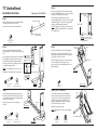
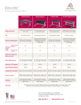
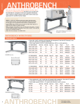
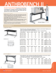
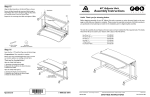
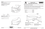
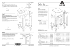
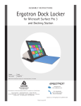
Step 7
72” AnthroBench
Place the Bench Shelf (laminate facing down) onto the floor.
With the help of another person, carefully rotate the Leg
Assembly (from Step 6) over onto the Shelf.
Assembly Instructions
Pans
Position the holes on the Pans and Arms to align with the
twelve predrilled holes on the Shelf. Insert two Wood
Screws through each center opening of the Bench Pans
(shown encircled at right).
These Assembly Instructions are for the 72” AnthroBench models: B7229zz/xx, S7229zz/xx, B7235zz/xx
& S7235zz/xx. Before beginning assembly of your AnthroBench, please take a moment to review the parts listed below
to verify that your shipment is complete.
Arms
Install the remaining Wood Screws into each of the Arms and
Pans, a total of twelve Wood Screws will be installed.
In preparation for Step 8, carefully rotate your AnthroBench
back over onto the Glides.
Your AnthroBench is heavy!
A second person will make this
assembly procedure much easier.
Predrilled holes
11/4” Wood Screw
325-5178-00
TECHNOLOGY FURNITURE®
01
20
02
*Does your Bench have 5” Casters?
(If you purchased a 640RT, your
03
Caster Part Numbers are given here.)
Rounded Edge of Shelf
22
18
5” Non-Locking Caster
150-5025-00
05
5” Locking Caster
150-5024-00
SECOND- position one Cross End on the remaining
Buttress end and install a Pan Screw and Keps Nut in the
same manner, but do not fully tighten.
THIRD- rotate the Buttress to align the Cross End with
two openings on the Leg. Secure the Cross End to the
Leg using two Support Screws.
06
Back Pan hole
first Install this Pan Screw
Buttress
NOTE: The purpose of the Buttress is not to support
your Bench Shelf. It is intended to make your Bench
absolutely rigid under extreme weight conditions.
Support Screw
325-5010-00
Removal of Leg Covers & Cable Grommets
Cable Grommets are snapped into and out of each of the
circular Leg openings.
Workstation Screw
(not counted in Parts List)
325-5092-00
Cable Grommet
Lower Metal Mounts
Questions?
14
15
16
10
Enclosed Parts List
third Install the Cross End
second Install this Pan Screw
Remove the Leg Cover by: 1. Using the Anthro driver,
remove the top two Workstation Screws. 2. Lift and tilt the
Cover up and free of the lower metal mounts.
13
09
Thank you for choosing Anthro!
(1/4-20) Keps Nut
325-5130-03
11
08
Tighten all Pan Screws, Support Screws & Keps Nuts.
Congratulations! Your 72” AnthroBench assembly is
complete. Please return the enclosed Registration Card to
receive our product updates, new catalogs, and sale flyers.
12
07
Repeat this entire procedure for the remaining Buttress
and Cross End on the opposite end.
(1/4-20 X .5”) Pan Screw
325-5003-00
17
19
04
Step 8 (requires a 3-Way Wrench)
FIRST- from the rear of your Bench, align one Buttress
with one hole on the Back Pan. Install a Pan Screw
through the Buttress and loosely capture using a Keps Nut
on the opposite side.
21
1-800-325-3841
Detailed views of all Hardware is provided with each Assembly Step
01–30” Wide Bench Shelf............Qty. 1 ..................(see below)
28” Deep (S7229zz/xx & S7235zz/xx)..............100-6408-00
36” Deep (B7229zz/xx & B7235zz/xx).............100-6351-00
02–Bench Leg Assemblies............Qty. 2...................(see below)
25” Bench Legs (S7229zz/xx & S7235zz/xx).. 835-5008-00
31” Bench Legs (B7229zz/xx & B7235zz/xx) 835-5009-00
03–Bench Arm Left ......................Qty. 1..............225-5357-00
04–Cross Ends.................................Qty. 2 .............225-5334-00
05–11/4” Wood Screws..................Qty. 12............325-5178-00
06–Glide Insert Screws................Qty. 4..............325-5052-00
07–2.5” End Caps...........................Qty. 4 .............175-5158-00
08–Glide Inserts..............................Qty. 4..............525-5030-00
09–Glides (1/2-13 X 2”).................Qty. 4............325-5165-00* 10–Cap Screws (5/16-18 X 4”)....Qty. 8..............325-5166-00
11–Curved Washers......................Qty. 8.. 225-2050-00 or 225-3522-00
12–Bench Base Tubes....................Qty. 2...................(see below)
28” Deep (S7229zz/xx & S7235zz/xx)..............125-5225-00
36” Deep (B7229zz/xx & B7235zz/xx).............125-5183-00
13–20” Bench Buttress.................Qty. 2..............225-5388-00
14–65.5” Bench Cross Tubes.....Qty. 2..............125-5186-00
15–Keps Nuts (1/4-20)...................Qty. 8..............325-5130-00
16–Pan Screws (1/4-20 X .5”).....Qty. 8..............325-5003-00
17–Bench Arm Right......................Qty. 1..............225-5358-00
18–Support Screws........................Qty. 20............325-5010-00
19–72” Bench Pans........................Qty. 2..............225-5372-00
All Screw quantities listed here are the minimum needed
for your Bench assembly. There may be a few extra
Screws included, which are not counted in the Parts List.
To make the assembly of your Anthro Bench even easier, we
have included the required tools. The handy Hex Driver Bit can
be used in your electric drill in place of the Hex Driver.
20 - Hex Driver 5/32”......................Qty. 1..............375-5000-00
21 - Hex Driver Bit 5/32”...............Qty. 1..............375-5003-00
22 - Hex Key 1/4”..............................Qty. 1..............375-5024-00
3-Way Wrench (not shown)..........Qty. 1..............225-5196-03
Anthro Corporation Technology Furniture® 10450 SW Manhasset Drive Tualatin, Oregon 97062
Feb. 2002 Rev. E
SAVE THESE INSTRUCTIONS!
anthro.com
72” AnthroBench
Step 4
Assembly Instructions
Questions? 1-800-325-3841
Step 1
Leave these two holes open
Install two Bench Glide Inserts into each Bench Base Tube
and secure with one Insert Screw per Insert.
Pop two End Caps into the ends of both Base Tubes.
Determine the height of your Shelf. These Instructions will
place your final Shelf height at either 29” or 35” from the floor
(depending on which height Bench you purchased).
The holes along the Leg Assemblies are spaced at 1”
increments. Adjusting either one hole up or down will modify
the final Shelf height by 1” respectively. Rotating the Glides
will also provide additional height adjustment.
29” or 35”
NOTE:Your Shelf height can be adjusted at a later time if needed,
however, Assembly Steps 5 through 8 will need to be disassembled
and reassembled again.
Glide Inserts placed
into the large holes
Reminder: You may want to measure
your equipment to make sure it fits into
the selected Shelf location.
Insert Screw
(small pink patch on end)
325-5052-00
Step 2
Left Leg
Assembly
Orient one Bench Leg Assembly with one Base Tube
Assembly (from Step 1). The Glide Inserts should be facing
down.
Insert one Bench Cap Screw through one Curved Washer,
then carefully insert through one of the lower holes on
the Base Tube, threading into the Right Leg Assembly.
Position the Left Bench Arm onto the Left Leg Assembly.
Lower holes
Finally, thread one Bench Glide into each Glide Insert.
Thread one Glide
into each Glide
Inser t AFTER the
BaseTubes have been
installed to the Legs.
Left Leg Assembly
Right Leg Assembly
Support Screw
325-5010-00
Step 3
Step 6 (requires a 3-Way Wrench)
Position the Right Leg Assembly (from Step 2) with two
Cross Tubes as shown. Insert one Bench Cap Screw with
a Curved Washer through a side hole, carefully threading
the Screw into the Cross Tube.
Position a Bench Pan between the Arms, aligning the
two tabs on each Arm with the two holes in the lower
corners of a Pan. Insert a Pan Screw through the Pan
and Arm Tab capturing it with a Keps Nut (but do not
fully tighten). Repeat this procedure for the remaining
end of the Pan and for the second Pan.
Repeat entire procedure for the remaining three
side holes.
Left Bench Arm
Repeat entire procedure for the Right Bench Arm on the
Right Leg Assembly.
Leave these two holes open
Right Leg
Assembly
Curved Washer
225-2050-00 or 225-3522-00
Hole 2
Install the remaining six Support Screws into the Left Arm,
but do not fully tighten any of the Support Screws.
Glide Inserts
STOP: If you are upgrading to 5” Casters do so now.
Leave top two
holes open
Align the top two openings of the Arm with hole 2 of the
Leg Assembly. Loosely install a Support Screw through the
top two holes of the Arm into the Leg.
NOTE: Loosen these
Support Screws (if
needed) to allow the
Base Tube to install
easier.
Repeat this procedure for the remaining three lower holes
on the Right & Left Leg Assembly.
(5/16-18 X 4”) Bench Cap Screw
325-5166-00
Step 5
Cross Tubes
Left Leg Assembly
Arms
Tighten all Pan and Support Screws.
NOTE: the 3-Way Wrench can be used to assist in tightening
the Keps Nuts.
Second Pan shown installed
(5/16-18 X 4”) Bench Cap Screw
325-5166-00
Curved Washer
225-2050-00 or 225-3522-00
Side holes
Right Leg Assembly
Anthro Corporation Technology Furniture® 10450 SW Manhasset Drive Tualatin, Oregon 97062
(1/4-20 X .5”) Pan Screw
325-5003-00
(1/4-20) Keps Nut
325-5130-03
anthro.com