1
Installation Guide
2
7
Hardware Installation
2.1 Installation Instructions
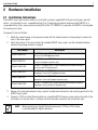
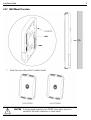
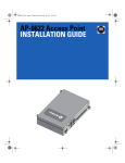
The AP6522 access point mounts either on a wall (with customer supplied M4 x 25 pan head screws and wall
anchor - or equivalent) or on a suspended ceiling T-bar. If deploying an external antenna model AP6522 on a
suspended ceiling T-bar, access point mounting kit (Part No. KT-135628-01) is required. An AP6522 is not designed
for mounting on a desk.
To prepare for the installation:
1. Match the model number on the purchase order with the model numbers in the packing list and on the
case of the access point.
2. Verify the contents of the box include the intended AP6522 access point, and the included hardware
matches the package contents on page 5.
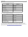
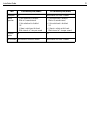
Part Number
Description
AP-6522-66030-US
Dual 802.11n radio AP6522. Plastic enclosure with internal antennas.
For use in the US deployments only.
AP-6522-66030-EU
Dual 802.11n radio AP6522. Plastic enclosure with internal antennas.
For use in European countries only.
AP-6522-66030-WR
Dual 802.11n radio AP6522. Plastic enclosure with internal antennas.
For use in non-US countries only.
AP-6522-66040-US
Dual 802.11n radio AP6522. Metal enclosure with external antenna
connectors. For use in US deployments only.
AP-6522-66040-EU
Dual 802.11n radio AP6522. Metal enclosure with external antenna
connectors. For use in European countries only.
AP-6522-66040-WR
Dual 802.11n radio AP6522. Metal enclosure with external antenna
connectors. For use in non-US countries only.
3. Review site survey and network analysis reports to determine the location and mounting position for the
AP6522 access point.
4. Connect a CAT-5 or better Ethernet cable to a compatible 802.3af power source and run the cable to the
installation site. Ensure there is sufficient slack on the cable to perform the installation steps.
NOTE
When operating in a Gigabit Ethernet environment, CAT-5e or CAT-6 cable
is recommended for Gigabit operation.