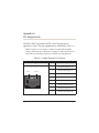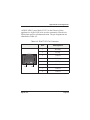
1
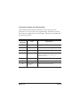
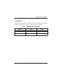
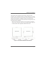
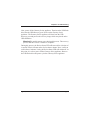
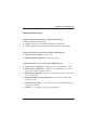
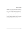
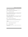
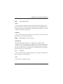
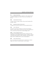
Gateway Series G100 / G200 Administrator Manual 601-00020 Rev. A1 Digium, Inc. 445 Jan Davis Drive Huntsville, AL 35806 United States Main Number: 1.256.428.6000 Tech Support: 1.256.428.6161 U.S. Toll Free: 1.877.344.4861 Sales: 1.256.428.6262 www.digium.com www.asterisk.org www.asterisknow.org © Digium, Inc. 2012 All rights reserved. No part of this publication may be copied, distributed, transmitted, transcribed, stored in a retrieval system, or translated into any human or computer language without the prior written permission of Digium, Inc. Digium, Inc. has made every effort to ensure that the instructions contained in this document are adequate and error free. The manufacturer will, if necessary, explain issues which may not be covered by this documentation. The manufacturer’s liability for any errors in the documents is limited to the correction of errors and the aforementioned advisory services. This document has been prepared for use by professional and properly trained personnel, and the customer assumes full responsibility when using it. Adobe and Acrobat are registered trademarks, and Acrobat Reader is a trademark of Adobe Systems Incorporated. Asterisk, Digium, Switchvox, and AsteriskNOW are registered trademarks and Asterisk Business Edition, AsteriskGUI, and Asterisk Appliance are trademarks of Digium, Inc. Any other trademarks mentioned in the document are the property of their respective owners. Digium, Inc. Page 2 Safety Certification and Agency Approvals Safety: UL 60950-1, 2nd Edition CSA C22.2 No. 60950-1-07, 2nd Edition IEC 60950-1:2005 (2nd Edition) +A1:2009 EN 60950-1:2006 (2nd Edition) +A11:2009 +A1:2010 AS/NZS 60950-1 1st Edition Other: CE Mark (European Union) 2002/95/EC Restrictions on Hazardous Substances (RoHS), 2005/747/EC lead free exemption (Annex C) EMC: FCC 47 CFR Part 15 Subpart B, Class A Industry Canada ICES-003 Issue 4, Class A EN 55022:2010, Class A EN 55024:2010 EN 61000-3-2:2006 w/A1 and A2 EN 61000-3-3:2008 AS/NZS CISPR 22:2006, Class A Digium, Inc. Page 3 FCC Part 15 This equipment has been tested and found to comply with the limits for a Class A digital device, pursuant to Part 15 of the FCC Rules. These limits are designed to provide reasonable protection against harmful interference in a residential installation. This equipment generates, uses, and can radiate radio frequency energy and, if not installed and used in accordance with the instructions, may cause harmful interference to radio communications. Operation of this device in a residential area is likely to cause harmful interference in which case the user will be required to correct the interference at his own expense. Industry Canada This Class A digital apparatus meets all requirements of the Canadian Interference Causing Equipment Regulations. Operation is subject to the following two conditions; (1) this device digital apparatus meets all requirements of the Canadian Interference Causing Equipment Regulations. Operation is subject to the following two conditions; (1) this device may not cause harmful interference, and (2) this device must accept any interference received, including interference that may cause undesired operation. Cet appareillage numérique de la classe A répond à toutes les exigences de l'interférence canadienne causant des règlements d'équipement. L'opération est sujette aux deux conditions suivantes: (1) ce dispositif peut ne pas causer l'interférence nocive, et (2) ce dispositif doit accepter n'importe quelle interférence reçue, y compris l'interférence qui peut causer l'opération peu désirée. Digium, Inc. Page 4 Introduction to Gateway Series Documentation This manual contains product information for the Gateway Series appliances. Be sure to refer to any supplementary documents or release notes that were shipped with your equipment. The manual is organized in the following manner: Chapter/ Appendix Title Description 1 Overview Identifies the features of your unit. 2 Unit Installation Provides instructions for installing the unit. 3 Configuration Provides instructions on how to configure the unit. 4 Troubleshooting Explains resolutions to common problems and frequently asked questions pertaining to unit installation and usage. A Pin Assignments Describes the states supported by the unit. B Specifications Details unit specifications. C Glossary and Acronyms Defines terms related to this product. Digium, Inc. Page 5 Symbol Definitions Caution statements indicate a condition where damage to the unit or its configuration could occur if operational procedures are not followed. To reduce the risk of damage or injury, follow all steps or procedures as instructed. The ESD symbol indicates electrostatic sensitive devices. Observe precautions for handling devices. Wear a properly grounded electrostatic discharge (ESD) wrist strap while handling the device. The Electrical Hazard Symbol indicates a possibility of electrical shock when operating this unit in certain situations. To reduce the risk of damage or injury, follow all steps or procedures as instructed. Digium, Inc. Page 6 Important Safety Instructions Servicing. Do not attempt to service this unit. There are no user-serviceable parts inside. Refer servicing to qualified service personnel. Batteries. The batteries in the unit are not user-serviceable. Refer servicing to qualified service personnel. CAUTION - Risk of explosion if battery is replaced by an incorrect type. Batteries should be disposed of according to the local laws and regulations of your region. ATTENTION - II y a danger d’explosion s’il y a remplacement incorrect de la batterie. Remplacer uniquement avec une batterie du même type ou d’un type equivalent recommandé par le constructeur.Mettre au rebut les batteries usages conformément aux instructions du fabricant. Water and Moisture. Do not spill liquids on this unit. Do not operate this equipment in a wet environment. Heat. Do not operate or store this product near heat sources such as radiators, air ducts, areas subject to direct, intense sunlight, or other products that produce heat. Caution. To reduce the risk of fire, use only No. 26 AWG or larger telecommunication wiring for network connections. Static Electricity. To reduce the risk of damaging the unit or your equipment, do not attempt to open the enclosure or gain access to areas where you are not instructed to do so. Refer servicing to qualified service personnel. Save these instructions for future reference. Digium, Inc. Page 7 TABLE OF CONTENTS Chapter 1 Overview . . . . . . . . . . . . . . . . . . . . . . . . . . . . . . . . . . . . . . . . . . . . . . . 12 Echo-Cancellation . . . . . . . . . . . . . . . . . . . . . . . . . . . . . . . . . . . . . . 15 Chapter 2 Unit Installation . . . . . . . . . . . . . . . . . . . . . . . . . . . . . . . . . . . . . . . . . . 16 Unpacking the Unit . . . . . . . . . . . . . . . . . . . . . . . . . . . . . . . . . . . . . 17 Shipment Inspection . . . . . . . . . . . . . . . . . . . . . . . . . . . . . . . . . . . . 18 Front Panel Identification . . . . . . . . . . . . . . . . . . . . . . . . . . . . . . . . 19 Unit Identification . . . . . . . . . . . . . . . . . . . . . . . . . . . . . . . . . . . . . . 22 Hardware Installation . . . . . . . . . . . . . . . . . . . . . . . . . . . . . . . . . . . 23 Connecting to the Gateway Series . . . . . . . . . . . . . . . . . . . . . . . . . 32 Chapter 3 Configuration . . . . . . . . . . . . . . . . . . . . . . . . . . . . . . . . . . . . . . . . . . . . 39 Settings and Configuration . . . . . . . . . . . . . . . . . . . . . . . . . . . . . . . 43 Logging and Reporting . . . . . . . . . . . . . . . . . . . . . . . . . . . . . . . . . . 47 Status and Diagnostics . . . . . . . . . . . . . . . . . . . . . . . . . . . . . . . . . . 48 Maintenance . . . . . . . . . . . . . . . . . . . . . . . . . . . . . . . . . . . . . . . . . . 50 Chapter 4 Troubleshooting . . . . . . . . . . . . . . . . . . . . . . . . . . . . . . . . . . . . . . . . . 52 Frequently Asked Questions . . . . . . . . . . . . . . . . . . . . . . . . . . . . . . 55 Free Installation Support . . . . . . . . . . . . . . . . . . . . . . . . . . . . . . . . .58 Digium, Inc. Page 8 Table Of Contents Appendix A Pin Assignments . . . . . . . . . . . . . . . . . . . . . . . . . . . . . . . . . . . . . . . . . 59 Appendix B Specifications . . . . . . . . . . . . . . . . . . . . . . . . . . . . . . . . . . . . . . . . . . . 61 Appendix C Glossary and Acronyms . . . . . . . . . . . . . . . . . . . . . . . . . . . . . . . . . . . 62 Digium, Inc. Page 9 List of Figures Figure 1: Figure 2: Figure 3: Figure 4: Figure 5: Figure 6: Figure 7: Figure 8: Figure 9: Digium, Inc. TDM PBX to VoIP Scenario . . . . . . . . . . . . . . . . . . . 14 VoIP PBX to TDM Scenario . . . . . . . . . . . . . . . . . . . 14 G100 Single Port Appliance . . . . . . . . . . . . . . . . . . . 19 G200 Dual Port Appliance . . . . . . . . . . . . . . . . . . . . 20 Side-by-side Rack Mounting . . . . . . . . . . . . . . . . . . . 28 Acceptable Wall Mount Orientations . . . . . . . . . . . . .29 IP Configuration Menu . . . . . . . . . . . . . . . . . . . . . . .35 Login Screen . . . . . . . . . . . . . . . . . . . . . . . . . . . . . . . 40 Main Menu . . . . . . . . . . . . . . . . . . . . . . . . . . . . . . . . 42 Page 10 List of Tables Table 1: Table A-1: Table A-2: Digium, Inc. Gateway Series Models. . . . . . . . . . . . . . . . . . . . . . 22 Gigabit Ethernet Port Pinouts . . . . . . . . . . . . . . . . . . 59 RJ45 T1/E1 Port Connector. . . . . . . . . . . . . . . . . . . .60 Page 11 Chapter 1 Overview Digium's Gateway Series is a converged media gateway product line designed to interface between TDM (T1/E1) and IP networks (SIP). The Gateway Series connects legacy telephone systems to IP networks and seamlessly integrates VoIP PBXs with the PSTN. Powered by innovative hardware and software solutions, Digium’s Gateway Series are managed by a simple, intuitive web-based interface. Digium, Inc. Page 12 Chapter 1: Overview Supported Voice Modes: PRI CPE and PRI NET (T1 / E1) – National ISDN 1 / NI1 – National ISDN 2 / NI2 – EuroISDN – 4ESS (AT&T) – 5ESS (Lucent) – DMS100 – Q.SIG E&M (T1 only) – Wink – Feature Group B – Feature Group D FXO and FXS (T1 only) – Ground Start – Loop Start – Loop Start with Disconnect Detect SIP Example scenarios utilizing the Gateway Series are illustrated in Figure 1 and Figure 2 on page 14. Digium, Inc. Page 13 Chapter 1: Overview Figure 1: TDM PBX to VoIP Scenario Figure 2: VoIP PBX to TDM Scenario Digium, Inc. Page 14 Chapter 1: Overview Echo-Cancellation Administrators connecting their Gateway Series appliances to the PSTN or other devices are likely to be placing calls that will result, at some point, in an unbalanced 4-wire/2-wire hybrid. The result of this hybrid is the reflection of a near-end echo to the calling party. Elimination of this echo is the responsibility of echo cancellation. The Gateway Series appliance utilizes hardware-based voice processors for echo cancellation and codec transcoding. Its hardware echo canceller is designed to handle up to 128ms of echo cancellation across all channels and provides a G.168 compliant echo cancellation solution. If not explicitly disabled in the Gateway Series web GUI, the hardwarebased echo canceller will automatically operate and cancel all network echo within its tail range (1024 taps). Digium, Inc. Page 15 Chapter 2 Unit Installation This chapter provides the following information: Unpacking the Unit on page 17 Shipment Inspection on page 18 Front Panel Identification on page 19 Unit Identification on page 22 Hardware Installation on page 23 Note: The Gateway Series appliance installation instructions are written so that they will apply to any model in the series. Examples and model specific information are included as needed. Digium, Inc. Page 16 Chapter 2: Unit Installation Unpacking the Unit When you unpack your unit, carefully inspect it for any damage that may have occurred in shipment. If damage is suspected, file a claim with the carrier and contact the reseller from which the unit was purchased. If the unit was purchased direct from Digium, contact Digium Technical Support at +1.256.428.6161. Keep the original shipping container to use for future shipment or proof of damage during shipment. Note: Only qualified service personnel should install the unit. Users should not attempt to perform this function themselves. The installer must ensure that the equipment is reliably earth grounded in accordance with the National Electrical Code. Digium, Inc. Page 17 Chapter 2: Unit Installation Shipment Inspection The following items are included in shipment of a Gateway Series appliance: Gateway Series appliance Power cord with attached T1/E1 loopback plug Mounting brackets (2 each) Bracket mounting screws, #8-32 black truss head, Phillips, 3/16” length (6 each) Side-by-side mounting screws, #6-32 pan head, Phillips, 3/16” length (3 each) Side-by-side mounting shoulder washers (3 each) Rubber feet (4 each) Ground nut Double-crimp ground ring terminal Quickstart Guide Note: After inspecting the shipment, Digium requires that the appliance be registered for support eligibility. Unregistered appliances are not eligible for Digium support. Please refer to Free Installation Support on page 58 for additional information on how to obtain assistance from Digium Technical Support. Digium, Inc. Page 18 Chapter 2: Unit Installation Front Panel Identification This section describes the components on the front panel of the Gateway Series models. USB Recovery Gigabit Ethernet Device Status Ethernet Status T1/E1 Status T1/E1 Port Figure 3: G100 Single Port Appliance Digium, Inc. Page 19 Chapter 2: Unit Installation USB Recovery Gigabit Ethernet Device Status Ethernet Status T1/E1 Status T1/E1 Port Figure 4: G200 Dual Port Appliance Device Status - This LED corresponds to the status of the Gateway Series appliance. See Frequently Asked Questions on page 55 for more information. Gigabit Ethernet - This 10/100/1000BaseT Ethernet port provides the ability to connect to an internal or external network using an RJ45 interface and supports Auto-MDIX. It is used to pass Ethernet packetized voice and web management data between the Gateway Series and the network. See Gigabit Ethernet Port Pinouts on page 59 for more information. Ethernet Status - These LEDs correspond to the status of the Ethernet connection. See Frequently Asked Questions on page 55 for more information. Digium, Inc. Page 20 Chapter 2: Unit Installation USB Recovery - This port can be used to perform a firmware recovery and configuration reset. See Firmware Recovery and Configuration Reset on page 53 for more information. Warning! The USB Recovery port provides a limited amount of current which is sufficient only to power a USB flash drive. Do not connect any other type of device to this port. The USB flash drive should be fully USB 2.0 compliant. T1/E1 Port(s) - These ports are used for connecting T1 or E1 cables. See RJ45 T1/E1 Port Connector on page 60 for more information. T1/E1 Status - These LEDs correspond to the status of the T1/E1 ports. See Frequently Asked Questions on page 55 for more information. Digium, Inc. Page 21 Chapter 2: Unit Installation Unit Identification The defining characteristic of the Gateway Series models are the number of ports supported. See Table 1 for a list of the various models. Table 1: Gateway Series Models Model Type Ports G100 T1/E1 1 G200 T1/E1 2 Digium, Inc. Page 22 Chapter 2: Unit Installation Hardware Installation This section describes how to properly install the hardware for a Gateway Series appliance. Caution Only qualified service personnel should continue with hardware installation and configuration of the Gateway Series appliance. Users should not attempt to perform these functions themselves. Caution This equipment is intended for use in Restricted Access Areas only where equipotential bonding has been applied. Grounding The Gateway Series appliance must be properly earth grounded for safety reasons. If the unit is not properly earth grounded, the unit and/or other equipment connected to the unit could be damaged. If a Gateway Series appliance is damaged while it is improperly grounded, the warranty on the Gateway Series appliance is void. A ground lug is located on the opposite side from the front panel of a Gateway Series appliance. Attach an appropriate length and gauge of wire to the double-crimp ground ring terminal. The wire length should be as short as possible, and gauge should be 18 AWG or greater. Stranded or solid wire is acceptable. Wire is not provided with the Gateway Series appliance. Double crimp the ground ring terminal to the wire. Next, slide the ground ring terminal over the ground lug. Then fasten the ground ring Digium, Inc. Page 23 Chapter 2: Unit Installation terminal to the ground lug using the ground nut. The ground nut must be turned clockwise to tighten it onto the ground lug. The opposite end of the wire that is connected to the ground ring terminal should be securily fastened to an unpainted metalic section of a properly earth grounded equipment rack. A connector for the opposite end of the wire is not provided with the Gateway Series appliance. Note: Taking into consideration the requirements of all equipment that is connected to or sharing the rack, the equipment rack should be properly earth grounded. Refer to the manufacturer of the rack for instructions on how to properly earth ground the rack. Important Use only a grounded electrical outlet when connecting the Gateway Series appliance to a power source. If you do not know whether the outlet is grounded, consult with a qualified electrician. Digium, Inc. Page 24 Chapter 2: Unit Installation Mounting The included hardware allows the Gateway Series appliance to be wall mounted, rack mounted side-by-side with another Gateway Series appliance, or placed flat on a level surface. If a single Gateway Series appliance is to be rack mounted, the optional long mounting bracket (not supplied, part number 3244-00042) must be used. The optional long mounting bracket can be ordered by contacting a Digium reseller or Digium directly. Important Reliable earth grounding of rack-mount equipment should be maintained. Particular attention should be given to provide connection other than direct connections to the branch circuit (e.g., use of power strips). Important Mounting of the Gateway Series appliance in a rack should be such that no hazardous condition is achieved due to uneven mechanical loading. Do not place heavy objects on top of the unit, or pull down on the mounted unit. Consider the mechanical loading of external cables. The weight of the cables can pull on the unit and create uneven loading. Secure heavy cables with external cable trays. Important If rack mounting, install the Gateway Series appliance in a rack so that the amount of airflow required for safe operation is not compromised. Digium, Inc. Page 25 Chapter 2: Unit Installation Important If the Gateway Series appliance is installed in a system that is in turn installed in a closed or multi-unit rack assembly, the operating ambient temperature of the rack environment may be significantly greater than the room ambient. While the maximum safe operating temperature is 50°C, consideration should be given to installing the unit in an environment compatible with the maximum recommended ambient temperature of 45°C for long term reliability and maximum performance. Single Unit Rack Mount: In order to rack mount the Gateway Series appliance by itself, place one of the short mounting brackets on the front of one side of the Gateway Series appliance. Line up the holes from the mounting bracket to the threaded holes on the front side of the Gateway Series appliance. Two #8 black truss head screws should be inserted and turned clockwise to fasten the mounting bracket. Do not over-tighten. Repeat these steps when installing the optional long mounting bracket (not supplied, part number 3244-00042) on the other side of the Gateway Series appliance. Then use another 2 #8 black truss head screws on each mounting bracket to secure the Gateway Series appliance to a rack. Digium, Inc. Page 26 Chapter 2: Unit Installation Side-by-side Rack Mount: In order to rack mount the Gateway Series appliance side-by-side with another Gateway Series appliance, place one of the short mounting brackets on the front of the left side of the first Gateway Series appliance. Line up the holes from the mounting bracket to the threaded holes on the front of the left side of the first Gateway Series appliance. Two #8 black truss head screws should be inserted and turned clockwise to fasten the mounting bracket. Repeat these steps when installing a short mounting bracket on the front of the right side of the second Gateway Series appliance. Each of the three #6 pan head screws should be inserted into a shoulder washer as shown in Figure 5 on page 28. Make sure the narrow side of the shoulder washer is away from the head of the screw. The three screws should then be inserted and turned clockwise to fasten to the side-by-side holes on the right side of the first Gateway Series appliance. Do not overtighten the screws or the shoulder washers could be damaged. Connect the first and second Gateway Series appliances together by putting the heads of three screws & shoulder washers into the three keyed insets. Then push down on the second Gateway Series appliance as shown in Figure 5. Make sure the units are flat against each other before pushing the second unit down. Otherwise the shoulder washers may be damaged. Use two truss head screws (not supplied) on each mounting bracket to secure both Gateway Series appliances to a rack. Digium, Inc. Page 27 Chapter 2: Unit Installation Figure 5: Side-by-side Rack Mounting Wall Mount: In order to wall mount the Gateway Series appliance, the short mounting brackets should be flipped and rotated, and fastened on the middle of the right and left sides of the Gateway Series appliance as shown in Figure 6 on page 29. The unit should be mounted at or below eye level to properly view the LEDs. In addition, the Gateway Series appliance should be properly oriented as shown in Figure 6. Orientations other than those shown in Figure 6 are not acceptable. Digium, Inc. Page 28 Chapter 2: Unit Installation If the Gateway Series appliance is placed in the “right side down” orientation, the 2 remaining #8 black truss head mounting screws should be fully inserted into the screw holes near the front of the right side of the Gateway Series appliance. In addition, the three #6 pan head screws should be fully inserted into the side-by-side holes on the right side of the first Gateway Series appliance. Note: The Gateway Series appliance must be properly grounded for safety reasons. If the unit is not properly grounded, damage could arise to the unit and/or other equipment connected to the unit. Right side down Front side Back side Back side down Left side Right side Figure 6: Acceptable Wall Mount Orientations Digium, Inc. Page 29 Chapter 2: Unit Installation Level Surface: In order to place the Gateway Series appliance flat on a level surface, the rubber feet should be adhered to the 4 corners of the bottom of the Gateway Series appliance. This will help secure the Gateway Series appliance to the surface it is placed on. Note: The Gateway Series appliance must be properly grounded for safety reasons. If the unit is not properly grounded, damage could arise to the unit and/or other equipment connected to the unit. Digium, Inc. Page 30 Chapter 2: Unit Installation Connecting Ports A description of each of the front panel connectors on a Gateway Series appliance is available in the section titled Front Panel Identification on page 19. Please refer to that section to determine what should be connected to each connector. Caution This unit must be connected to the Telecommunications Network in your country using an approved line cord, e.g.: for Australia use only line cords complying with ACA Technical Standard TS008. Caution Connect only equipment approved for use in your specific country to the telecommunications network voltage circuit ports. Connections to a Gateway Series appliance should be made in the following order. 1. Gigabit Ethernet 2. T1/E1 Port(s) 3. Power Cord Digium, Inc. Page 31 Chapter 2: Unit Installation Connecting to the Gateway Series The Gateway Series web GUI may be accessed by either its DHCP or statically assigned IP address. The following browsers are supported: IE 9 Firefox 8 or newer Chrome 15 Safari 5 Connecting via DHCP assigned IP address 1. If a DHCP server exists on the network that the Gateway Series appliance will be placed on, connect one end of an Ethernet cable to the Gateway Series appliance's Ethernet port, and the other end to an Ethernet connection on a network switch or hub. This step will connect your Gateway Series appliance to your network so that the Gateway Series web GUI may be accessed from your network. 2. Using a Gateway Series supported web browser, open a browser window from a computer on your network and enter the IP address for the Gateway Series appliance using HTTPS (e.g. https://[IP]). If you do not connect using HTTPS, a browser error will be displayed. The IP address for the Gateway Series web GUI will be assigned by the DHCP server on the network. The DHCP server on the network will need to be accessed to determine the IP address assigned to the Digium, Inc. Page 32 Chapter 2: Unit Installation Gateway Series appliance. The default username for the Gateway Series web GUI is admin, and the default password is admin. Note: The Gateway Series appliance may also be accessed by its hostname. The hostname will be in the format of Gx00-aa-bb-cc, where x is 1 for G100 or 2 for G200, aa is the 6th to last and 5th to last alphanumeric of the unit’s MAC address, bb is the 4th to last and 3rd to last alphanumeric of the unit’s MAC address, and cc is the 2nd to last and very last alphanumeric of the unit’s MAC address. The MAC address of the Gateway Series appliance is printed on a label on the back of the unit. For example, if the MAC address of a G200 Gateway Series appliance is B2432B187135, the hostname will be G200-18-7135. HTTPS (e.g. https://[IP]) must be used. If you do not connect using HTTPS, a browser error will be displayed. 3. It is highly recommended that the admin password be changed using the System Administrators menu on the web GUI. 4. Next, the IP configuration options should be configured on the Gateway Series appliance. See IP Configuration on page 35. Connecting via Statically assigned IP address 1. If a DHCP server does not exist on the network that the Gateway Series appliance will be placed on, connect one end of an Ethernet cable to the Gateway Series appliance's Ethernet port, and the other end to an Ethernet connection on a computer. That computer will need to use the network configuration listed below. This step will connect your Gateway Series appliance to your computer so that the Digium, Inc. Page 33 Chapter 2: Unit Installation Gateway Series web GUI may be accessed from your computer. Network settings for computer connecting to Gateway Series IP: 192.168.69.2 Netmask: 255.255.255.0 Broadcast: 192.168.69.255 2. Using a Gateway Series supported web browser, open a browser window and enter the IP address for the Gateway Series appliance using HTTPS (e.g. https://[IP]). If you do not connect using HTTPS, a browser error will be displayed. The default IP address for the Gateway Series web GUI is 192.168.69.1. The default username for the Gateway Series web GUI is admin, and the default password is admin. 3. It is highly recommended that the admin password be changed using the System Administrators menu on the web GUI. 4. Next, the IP configuration options should be configured on the Gateway Series appliance. See IP Configuration on page 35. Digium, Inc. Page 34 Chapter 2: Unit Installation IP Configuration The general networking and configuration server options in the Gateway Series web GUI should be configured before others. Note: Saving changes to the IP configuration requires a restart, resulting in all active calls being dropped. We recommend against making these changes during business hours. Figure 7: IP Configuration Menu Digium, Inc. Page 35 Chapter 2: Unit Installation The General Networking Options are described below. Hostname - Specify the hostname of the Gateway Series appliance. Obtain an IP Address via DHCP - If a DHCP server exists on the same network as the Gateway Series appliance, this feature may be enabled for the IP address to be dynamically assigned via DHCP. Note: It is recommended that this feature be disabled if the DHCP server is not configured to always provide the same IP address based on MAC address. If this is the case, the Gateway Series appliance’s network settings should be manually configured. The MAC address of the Gateway Series appliance is printed on a label on the back of the unit. System IP Address - If Obtain an IP Address via DHCP is disabled, specify the static IP address for the Gateway Series appliance. Note: If a static IP address is assigned using this feature, the Gateway Series appliance will immediately be unresponsive from its old IP address. It may take up to 15 seconds for the new IP address to be assigned and functional. The new IP address of the Gateway Series appliance must be entered into the browser and HTTPS (e.g. https://[IP]) must be used. If you do not connect using HTTPS, a browser error will be displayed. Network Mask - If Obtain an IP Address via DHCP is disabled, specify the network mask for the Gateway Series appliance. Gateway Address - If Obtain an IP Address via DHCP is disabled, specify the gateway address for the Gateway Series appliance. The gateway address is usually the address of the router on the network. DNS Addresses - If Obtain an IP Address via DHCP is disabled, specify up to 3 DNS servers to be used by the Gateway Series appliance. A DNS server may also be referred to as a nameserver. Digium, Inc. Page 36 Chapter 2: Unit Installation Also Continue Using Default Install IP Address - Leaving this option enabled will allow the Gateway Series appliance to listen for network requests on its factory default IP address. Note: For security purposes, it is recommended that this feature be disabled after initial IP configuration is complete. After this feature is disabled, the Gateway Series appliance will be accessible only from the IP address that is assigned by the DHCP server or statically configured. – Factory Default IP Address - Displays the factory default IP address assigned to the Gateway Series appliance. – Default Install Mask - Displays the factory default network mask of the Gateway Series appliance. The Gateway Series appliance is capable of loading its configuration from a configuration server on reboot. This allows Gateway Series appliances to be quickly and easily deployed at multiple locations with minimal interaction from an administrator. In order to generate a configuration to place on a configuration server, configure a Gateway Series appliance, generate a backup from the web GUI as described in Backups on page 50, and place the backup file on the configuration server at the path described below. Note: The format of the path to the configuration server is protocol:// [user:password@]hostname_or_ip[/path]. The protocol may be either tftp, ftp, or http. The Gateway Series appliance will request a configuration database with the filename of xxxxxxxxxxxx.tgz, where xxxxxxxxxxxx is the unit’s MAC address, from the configuration Digium, Inc. Page 37 Chapter 2: Unit Installation server. The MAC address of the Gateway Series appliance is printed on a label on the back of the unit. FTP and HTTP normally do not require a username and password. The Configuration Server options are specified below. Reload Remote Config on Reboot - Leaving this option enabled will allow the Gateway Series appliance to request that its configuration be reloaded from a configuration server on every reboot. Note: If this feature will not be used, it is recommended that it be disabled. Get Config Server from Option 66 via DHCP - If Obtain an IP Address via DHCP is enabled and the DHCP server specifies the path and configuration database file on the configuration server using Option 66, this feature may be enabled for all Gateway Series configuration settings to be automatically configured using a configuration server. The Reload Remote Config on Reboot option must be enabled in order to activate this feature. Refer to the note on page 37 for proper syntax when specifying the path and configuration database file. Configuration Server - If Obtain an IP Address via DHCP is enabled and Get Config Server from Option 66 via DHCP is disabled, the path to the configuration server may be statically defined using this option. The Reload Remote Config on Reboot option must be enabled in order to activate this feature. Refer to the note on page 37 for proper syntax when specifying the path and configuration database file. Digium, Inc. Page 38 Chapter 3 Configuration The Gateway Series appliances have a variety of configuration options. This chapter provides information on how to use the Gateway Series web GUI to configure an appliance without the need of command-line tools, and an overview of the available configuration sections. Context-sensitive help buttons are provided above most sections of the Gateway Series web GUI. Clicking on a help button will open a new window which contains a detailed description of the options available for that section. The help buttons appear as . Digium, Inc. Page 39 Chapter 3: Configuration The Gateway Series appliance should already be connected to your network or computer, as described in Connecting to the Gateway Series on page 32. Using a Gateway Series supported web browser, open a browser window and enter the IP address for the Gateway Series appliance using HTTPS (e.g. https://[IP]). If you do not connect using HTTPS, a browser error will be displayed. The login screen will be displayed. An administrator username and password must be entered to proceed. The default username for the Gateway Series web GUI is admin, and the default password is admin. Figure 8: Login Screen Digium, Inc. Page 40 Chapter 3: Configuration It is highly recommended that the software on a Gateway Series appliance be updated to the latest version before proceeding with configuration. See Software Updates on page 50. Digium, Inc. Page 41 Chapter 3: Configuration The Gateway Series web GUI is divided into the following main sections. Settings and Configuration on page 43 Logging and Reporting on page 47 Status and Diagnostics on page 48 Maintenance on page 50 Figure 9: Main Menu Digium, Inc. Page 42 Chapter 3: Configuration Settings and Configuration This section provides the ability to configure SIP and TDM settings, create call routing groups and rules, manage system administrators, and set up networking. Included are the following sections. SIP Endpoints on page 43 Advanced SIP Settings on page 44 T1/E1 on page 44 Call Routing Groups on page 44 Call Routing Rules on page 45 SIP Endpoints This section provides the ability to add and modify SIP endpoints, and configure call, media, and fax settings. A SIP endpoint will typically be a SIP PBX or SIP provider connected to the Gateway Series appliance. Included are the following sections. Main - Primary options for SIP endpoint configuration Call Settings (Advanced) - DTMF, Caller ID, signaling, and advanced timer settings Media Settings (Advanced) - Media types and priorities, codecs settings Fax Settings (Advanced) - Fax related settings Digium, Inc. Page 43 Chapter 3: Configuration Advanced SIP Settings This section provides the ability to add and modify advanced SIP settings. These settings are for experienced administrators only. Please take care when modifying any of these settings. The default values should be sufficient for most applications. Included are the following sections. Networking - General, NAT, RTP, RTCP, and DTMF settings Parsing and Compatibility - General, SIP methods, Caller ID, timer configuration, and outbound registrations Security - SIP domains and authentication settings Media - ISDN media, QOS/TOS settings Fax - Fax related settings T1/E1 This section provides the ability to configure the T1/E1 hardware in the Gateway Series appliance. Included are the following sections. General - General options for T1/E1 configuration Port # - Port specific options for interface type and signaling Call Routing Groups This section provides the ability to add and modify SIP and T1/E1 call routing groups. A call routing group allows a group of channels to be addressed when creating a call routing rule. Digium, Inc. Page 44 Chapter 3: Configuration Call Routing Rules This section provides the ability to add and modify call routing rules. A call routing rule determines how a call is handled based upon certain characteristics such as inbound channel and DID. It is also possible to manipulate matched numbers before connecting outbound calls. System Administrators This section provides the ability to add and modify system administrators for access to the Gateway Series web GUI. IP Configuration This section provides the ability to configure IP options for the Gateway Series appliance. See IP Configuration on page 35 for more information. HTTPS This section provides the ability to supply your own certificate for secure connection to the Gateway Series web GUI. A self-signed certificate is provided by default. Digium, Inc. Page 45 Chapter 3: Configuration Access Control This section provides the ability to limit access to the web GUI and SIP traffic through the Gateway Series appliance. All other protocols are blocked. Digium, Inc. Page 46 Chapter 3: Configuration Logging and Reporting This section provides the ability to configure and view system statistics and logging of the Gateway Series appliance. Included are the following sections. Statistics - Displays statistics for active calls and calls processed, and displays a summary of active calls in progress System Log - Settings for system logging via Syslog Digium, Inc. Page 47 Chapter 3: Configuration Status and Diagnostics This section provides the ability to view connection status, system information, perform advanced debugging, and troubleshoot problems with diagnostic tools. Included are the following sections. Connection Status on page 48 System Information on page 48 Advanced Debugging on page 49 Technical Support on page 49 Connection Status This section provides the ability to view the connection status of network interfaces, SIP endpoints, and T1/E1 interfaces. Included are the following sections. Network - Status of network interfaces SIP Endpoints - Status of SIP endpoints T1/E1 Interfaces - Status of T1/E1 interfaces per port System Information This section provides the ability to view system information on the Gateway Series appliance, including model number, software version, MAC address, uptime, and system time. Digium, Inc. Page 48 Chapter 3: Configuration Advanced Debugging This section provides the ability to record and download debug logs for troubleshooting. Included are the following sections. Debugging Sessions in Progress - Displays existing logs or recording sessions in progress Start a New Debugging Session - TCP traffic, gateway logging, and system logging settings for starting a new debugging session Technical Support This section provides the ability to enable remote access for Digium Support Personnel to access the Gateway Series appliance for support purposes. Digium, Inc. Page 49 Chapter 3: Configuration Maintenance This section provides the ability to perform configuration backups, perform system updates, set the system clock, reboot, and restore factory settings. Included are the following sections. Backups on page 50 Software Updates on page 50 System Clock on page 51 System Reset on page 51 Backups This section provides the ability to create and restore a backup. Included are the following sections. Download Backup - Download a backup in database format Note: At least one configuration change must be made before a backup can be generated and downloaded. In order to revert to the stock configuration, the factory reset feature referenced in the section titled System Reset on page 51 may be used. Restore a Backup - Restore a backup in database format Software Updates This section provides the ability to perform a software update for the Gateway Series appliance. If the Gateway Series appliance is connected to the Internet, you will be prompted if there is a newer version of the software available, and offered to automatically download and install it. Depending on the speed of your Digium, Inc. Page 50 Chapter 3: Configuration Internet connection, it may take a few minutes to complete downloading. The software update will take about 5 minutes to complete. If the Gateway Series appliance is not connected to the Internet, the latest software can be obtained at http://downloads.digium.com/pub/telephony/gateway/firmware/. Save the firmware file to your desktop. Then manually install it from the Software Updates section. Note: While many software versions may be available on Digium’s website, it is recommended to install only the latest version of the software. System Clock This section provides the ability to set the system clock on the Gateway Series appliance. System Reset This section provides the ability to perform a system reboot, system shutdown, or factory reset of the Gateway Series appliance. Note: The system shutdown feature should be used only to temporarily shut down a Gateway Series appliance before physically removing power. Power needs to be physically removed from the Gateway Series appliance within 2 minutes. Otherwise, the Gateway Series appliance will automatically reboot. A system shutdown will drop all current calls and cause the Gateway Series appliance to become unreachable by any method except physical access. Digium, Inc. Page 51 Chapter 4 Troubleshooting This chapter provides information regarding troubleshooting tools, frequently asked questions, and possible resolutions as identified by Digium Technical Support. Multiple resources are available to obtain more information about Asterisk and Digium products. Please visit both www.digium.com and www.asterisk.org for more information. Digium, Inc. Page 52 Chapter 4: Troubleshooting Firmware Recovery and Configuration Reset If a Gateway Series appliance is behaving unexpectedly or the password is forgotten, a firmware recovery may need to be performed. The USB Recovery port can be used to perform a firmware recovery using a recovery image. The recovery image reformats the Gateway Series’ root filesystem and reloads the appropriate software on it. It will also overwrite the configuration database, returning the Gateway Series appliance to its default configuration. Note: It is highly recommended to use an image that is equal or greater in version than the firmware that is currently installed on the Gateway Series appliance. Every Gateway Series firmware release will include a recovery image. The recovery image is located inside of a compressed zip file which can be downloaded from http://downloads.digium.com/pub/telephony/gateway/recovery/. After downloading the recovery image, the contents of the compressed zip file must be extracted and copied to the root (i.e. parent) directory of an empty USB flash drive. Note: A USB flash drive is not provided with a Gateway Series appliance. It must be purchased separately. The USB flash drive should be at least 2GB in size and formatted with the FAT32 filesystem. Note: Some decompression utilities will create a new directory in which to place extracted files. If your decompression utility functions in that way, be certain to copy the contents from that new directory to the root (i.e. parent) directory of an empty USB flash drive. Any new directory created by a decompression utility should not be copied. Digium, Inc. Page 53 Chapter 4: Troubleshooting Next, power off the Gateway Series appliance. Then insert the USB flash drive into the USB Recovery port. Power on the Gateway Series appliance. The Gateway Series appliance will boot from the USB Recovery port and process the recovery image which was placed on the USB flash drive. Warning! Do not disconnect power during this process. The recovery process will take at least 3 minutes to complete. During this process, the Device Status LED will turn red for a fraction of a second. Then it will turn amber for less than a minute. Next, it will run red for about 2 minutes. Lastly, the Device Status LED will remain off. At this point, it is safe to power off the Gateway Series appliance. Remove the USB flash drive and power cycle the Gateway Series appliance. Digium, Inc. Page 54 Chapter 4: Troubleshooting Frequently Asked Questions What do the colors of the Device Status LED indicate? Red - Hardware is initializing. Amber - Software is initializing. Hardware is initialized. Green - Hardware and software are fully initialized and running. What do the colors of the Ethernet Status LEDs indicate? Steady Green (left side) - Active Link Blinking Amber (right side) - Network activity What do the colors of the T1/E1 Status LEDs indicate? Steady Green (right side) - Appliance is in-sync with the far end. Steady Yellow (right side) - Appliance is synchronizing or is receiving a yellow alarm from the far end. Steady Red (right side) - Appliance is not seeing far end, circuit is not up, or cable is bad. Singular Blinking Green (right side) - Line has been placed into loopback mode. Steady Blue (left side) - T1/E1 software driver is initialized, but configuration is invalid. All Off - T1/E1 software driver is not initialized. Digium, Inc. Page 55 Chapter 4: Troubleshooting What type of cable do I need for the T1/E1 ports on a Gateway Series appliance? A straight-through RJ45 T1/E1 cable is needed for connecting to the RJ45 ports on a Gateway Series appliance when connecting to the PSTN. If connecting to a TDM PBX, a crossover RJ45 T1/E1 cable may be required. The appropriate cables may be ordered from Digium by visiting www.digium.com. Refer to Table A-2 on page 60 for pin assignments. There is a slight echo. How can I adjust the sound quality? First, verify that the Echo Cancellation option under the Port # menu of T1/E1 Settings is enabled. If it is not, enable it. If echo persists, adjust the RX Gain and TX Gain options on the same menu. For the gain options, it is recommended to shift only between values of -5 and 5. Digium, Inc. Page 56 Chapter 4: Troubleshooting Where can I find answers to additional questions? Digium Technical Support (+1.256.428.6161), or Toll Free in the U.S. (+1.877.344.4861), is available 7am-8pm Central Time (GMT -6), Monday - Friday. Please refer to Free Installation Support on page 58 for additional information on how to obtain assistance from Digium Technical Support. Digium, Inc. Page 57 Chapter 4: Troubleshooting Free Installation Support Digium hardware products include free installation support. In order to receive this support, register your Digium product using the serial number located on the serialization label of your Digium unit. Steps to receive installation support: 1. Record your product serial number. 2. Register your product at http://www.digium.com/register. 3. E-mail Digium Support via [email protected], or telephone via +1.256.428.6000 or Toll-Free +1.877.DIGIUM.1. Note: Digium does not provide support for unregistered products. Digium, Inc. Page 58 Appendix A Pin Assignments The RJ45 (8P8C) port labeled ETH on the Gateway Series appliance is 8-pin. The pin assignments are identified in Table A-1. Note: Category 5e or Category 6 cables are required for Gigabit (1Gbps) operation up to 100 meters. Category 5 cables will work for short runs, but the link speed may be limited over long distances. Table A-1: Gigabit Ethernet Port Pinouts Diagram Pin 1 Digium, Inc. Pin 8 Pin Description 1 Bi-directional pair A+ 2 Bi-directional pair A- 3 Bi-directional pair B+ 4 Bi-directional pair C+ 5 Bi-directional pair C- 6 Bi-directional pair B- 7 Bi-directional pair D+ 8 Bi-directional pair D- Page 59 Appendix A: Pin Assignments All RJ45 (8P8C) ports labeled T1/E1 on the Gateway Series appliance are 8-pin. RJ45 jacks are also commonly referred to as RJ48 when used for telecommunication. The pin assignments are identified in Table A-2. Table A-2: RJ45 T1/E1 Port Connector Pin 8 Digium, Inc. Pin Description 1 Rx Ring 2 Rx Tip 3 Unused 4 Tx Ring 5 Tx Tip 6 Unused 7 Unused 8 Unused Pin 1 Page 60 Appendix B Specifications This appendix provides specifications, required environmental conditions, and maximum power consumption for the Gateway Series appliances. Physical (All Units). Size: 8.6” × 9.0” × 1.72” (21.84 x 22.86 x 4.37 cm) Weight: 2 lbs 12 oz (1,247.38 gm) Interfaces. Local Loop Access: E1, T1, PRI; RJ45 (A.K.A RJ48) USB: Standard Type A Receptacle Ethernet Access: 10/100/1000base-T; RJ45 Power: Standard 3-pin IEC320-C13 Environment. Temperature: 0 to 50° C (32 to 122° F) operation -20 to 70° C (4 to 158° F) storage Humidity: 0 to 90% non-condensing Power Requirements. Voltage: 100-240VAC, 50/60Hz Current: 0.5A maximum, 67mA@120V or 33mA@240V typical Power: 10W maximum, 7.5W typical Digium, Inc. Page 61 Appendix C Glossary and Acronyms 8P8C 8 position 8 conductor Module connector commonly used to terminate twisted pair. ANSI American National Standards Institute An organization which proposes and establishes standards for international communications. asynchronous Not synchronized; not timed to an outside clock source. Transmission is controlled by start bits at the beginning and stop bits at the end of each character. Asynchronous communications are often found in internet access and remote office applications. attenuation The dissipation of a transmitted signal’s power as it travels over a wire. bandwidth The capacity to carry traffic. Higher bandwidth indicates the ability to transfer more data in a given time period. bit The smallest element of information in a digital system. A bit can be either a zero or a one. Digium, Inc. Page 62 Appendix C: Glossary and Acronyms bps bits per second A measurement of transmission speed across a data connection. BRI Basic Rate ISDN broadband Broadband transmission shares the bandwidth of a particular medium (copper or fiber optic) to integrate multiple signals. The channels take up different frequencies on the cable, integrating voice, data, and video over one line. channel A generic term for an individual data stream. Service providers can use multiplexing techniques to transmit multiple channels over a common medium. Cat5 Twisted pair cable for carrying signals for 10/100 Ethernet, telephony, and video. Cat5 was superseded by Cat5e. Cat5e Twisted pair cable for carrying signals for Gigabit Ethernet, telephony, and video. Digium, Inc. Page 63 Appendix C: Glossary and Acronyms CLEC Competitive Local Exchange Carrier A term for telephone companies established after the Telecommunications Act of 1996 deregulated the LECs. CLECs compete with ILECs to offer local service. See also LEC and ILEC. CO Central Office The CO houses local switching equipment. All local access lines in a particular geographic area terminate at this facility (which is usually owned and operated by an ILEC). CPE Customer Premises Equipment Terminal equipment which is connected to the telecommunications network and which resides within the home or office of the customer. This includes telephones, modems, terminals, routers, and television set-top boxes. DAHDI Digium Asterisk Hardware Device Interface A telephony project dedicated to implementing a reasonable and affordable computer telephony platform into the world marketplace. In addition, the collective name for the Digium-provided drivers for Digium telephony interface products. DS0 Digital Signal, Level 0 A voice grade channel of 64 kbps. The worldwide standard speed for digitizing voice conversation using PCM (Pulse Code Modulation). Digium, Inc. Page 64 Appendix C: Glossary and Acronyms DS1 Digital Signal, Level 1 1.544 Mbps in North America (T1) and Japan (J1) -up to 24 voice channels (DS0s), 2.048 Mbps in Europe (E1) - up to 32 voice channels (DS0s). DS1/T1/E1 lines are part of the PSTN. DS3 Digital Signal, Level 3 T3 in North America and Japan, E3 in Europe. Up to 672 voice channels (DS0s). DS3/T3/E3 lines are not part of the PSTN. DTMF Dual Tone Multi-Frequency Push-button or touch tone dialing. E1 The European equivalent of North American T1, transmits data at 2.048 Mbps, up to 32 channels (DS0s). E3 The European equivalent of North American T3, transmits data at 34.368 Mbps, up to 512 channels (DS0s). Equivalent to 16 E1 lines. EMI Electromagnetic Interference Unwanted electrical noise. full duplex Data transmission in two directions simultaneously. Digium, Inc. Page 65 Appendix C: Glossary and Acronyms FXO Foreign Exchange Office Receives the ringing voltage from an FXS device. Outside lines are connected to FXO ports. FXS Foreign Exchange Station Initiates and sends ringing voltage. Phones are connected to FXS ports. G.711 A recommendation by the Telecommunication Standardization Sector (ITU-T) for an algorithm designed to transmit and receive mulaw PCM voice and A-law at a digital bit rate of 64 kbps. G.723.1 A recommendation by the Telecommunication Standardization Sector (ITU-T) for an algorithm designed to transmit and receive audio at 6.3 kbps or 5.3 kbps. G.729a A recommendation by the Telecommunication Standardization Sector (ITU-T) for an algorithm designed to transmit and receive audio at 8 kbps. H.323 A recommendation by the Telecommunication Standardization Sector (ITU-T) for multimedia communications over packet-based networks. Digium, Inc. Page 66 Appendix C: Glossary and Acronyms HDLC High-Level Data Link Control A bit-oriented synchronous data link layer protocol developed by the International Organization for Standardization (ISO). IAX Inter-Asterisk eXchange The native VoIP protocol used by Asterisk. It is an IETF standard used to enable VoIP connections between Asterisk servers, and between servers and clients that also use the IAX protocol. iLBC internet Low Bitrate Codec A free speech codec used for voice over IP. It is designed for narrow band speech with a payload bitrate of 13.33 kbps (frame length = 30ms) and 15.2 kbps (frame length = 20ms). ILEC Incumbent Local Exchange Carrier The LECs that were the original carriers in the market prior to the entry of competition and therefore have the dominant position in the market. interface A point of contact between two systems, networks, or devices. ISO International Standards Organization IVR Interactive Voice Menu An interactive technology that allows a telephone system to detect voice and keypad input. Digium, Inc. Page 67 Appendix C: Glossary and Acronyms LED Light-emitting Diode Linux A robust, feature-packed open source operating system based on Unix that remains freely available on the internet. It boasts dependability and offers a wide range of compatibility with hardware and software. Asterisk is supported exclusively on Linux. loopback A state in which the transmit signal is reversed back as the receive signal, typically by a far end network element. MGCP Media Gateway Control Protocol multiplexing Transmitting multiple signals over a single line or channel. FDM (frequency division multiplexing) and TDM (time division multiplexing) are the two most common methods. FDM separates signals by dividing the data onto different carrier frequencies, and TDM separates signals by interleaving bits one after the other. mux multiplexer A device which transmits multiple signals over a single communications line or channel. See multiplexing. node A terminal in a computer network. Digium, Inc. Page 68 Appendix C: Glossary and Acronyms NT Network Termination A device connecting the customer's telephone or data equipment to the local ISDN exchange carrier's line. NT devices are connected to TE devices. PBX Private Branch Exchange A smaller version of a phone company’s large central switching office. Example: Asterisk. PCI peripheral component interconnect A standard bus used in most computers to connect peripheral devices. POP Point of Presence The physical connection point between a network and a telephone network. A POP is usually a network node serving as the equivalent of a CO to a network service provider or an interexchange carrier. POTS Plain Old Telephone Service The public switched telephone network (PSTN) is the network of the world's public circuit-switched telephone networks. Originally a network of fixed-line analog telephone systems, the PSTN is now almost entirely digital, and now includes mobile as well as fixed telephones. PPP Point-to-Point Protocol Type of communications link that connects a single device to another single device, such as a remote terminal to a host computer. Digium, Inc. Page 69 Appendix C: Glossary and Acronyms PRI Primary Rate ISDN PSTN Public Switched Telephone Network A communications network which uses telephones to establish connections between two points. Also referred to as the dial network. PTMP Point-to-Multipoint A connection where data is broadcast between more than two endpoints. PTP Point-to-Point A connection restricted to two endpoints. PTT Post, Telegraph, and Telephone The government agencies in many countries that traditionally operated and monopolized the public postal, telegraph, and telephone services. QoS Quality of Service A set of quality requirements for telephone service. RBOC Regional Bell Operating Companies The creation of Regional Bell Operating Companies were a result of AT&T's telephone monopoly being broken up in 1983. REN Ringer Equivalence Number An arbitrary value which denotes the electrical load a telephone ringer has on a line. Digium, Inc. Page 70 Appendix C: Glossary and Acronyms RJ11 A six-pin jack typically used for connecting telephones, modems, and fax machines in residential and business settings to PBX or the local telephone CO. RJ45 8P8C, un-keyed modular connector type for Ethernet over twisted pair. Predominantly used in LAN and uses Unshielded Twisted Pair cable. RJ48 8P8C modular connector type for T1 and ISDN termination over twisted pair. While RJ45 and RJ48 use the same connector, they differ in their wiring. RJ48 is commonly seen on T1 lines and uses Shielded Twisted Pair cable. SIP Session Initiation Protocol An IETF standard for setting up sessions between one or more clients. It is currently the leading signaling protocol for Voice over IP, gradually replacing H.323. T1 A dedicated digital carrier facility which transmits up to 24 voice channels (DS0s) and transmits data at 1.544 Mbps. Commonly used to carry traffic to and from private business networks and ISPs. T3 A dedicated digital carrier facility which consists of 28 T1 lines and transmits data at 44.736 Mbps. Equivalent to 672 voice channels (DS0s). Digium, Inc. Page 71 Appendix C: Glossary and Acronyms TDM Time Division Multiplexer A device that supports simultaneous transmission of multiple data streams into a single high-speed data stream. TDM combines signals by interleaving bits one after the other. TE Terminal Equipment A device that is established as a point of termination of a communications circuit or channel. Terminal equipment comprises all customer premises equipment (CPE). TE devices are connected to NT devices. telco A generic name which refers to the telephone companies throughout the world, including RBOCs, LECs, and PTTs. tip and ring The standard termination on the two conductors of a telephone circuit; named after the physical appearance of the contact areas on the jack plug. twisted pair Two copper wires commonly used for telephony and data communications. The wires are wrapped loosely around each other to minimize radio frequency interference or interference from other pairs in the same bundle. USB Universal Serial Bus Industry standard defining communication protocols, cables, and connectors used in a bus for connection, communication, and power between electronic devices and computers. Digium, Inc. Page 72 Appendix C: Glossary and Acronyms V Volts VoIP Voice over Internet Protocol Technology used for transmitting voice traffic over a data network using the Internet Protocol. Digium, Inc. Page 73