1
AMP 100
OWNER’S MANUAL
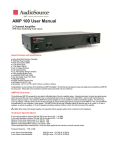
AMP 100
STEREO POWER AMPLIFIER
Balance
Volume
SPEAKERS
POWER
A
1
B
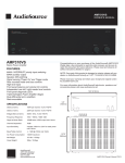
Figure 1. Front Panel
FRONT PANEL CONTROLS
3. Balance
Fades speaker output between the Right and Left Channels
4. Volume
Adjusts amplifier volume.
1. Power Switch
Switches the AMP100 on or off. A red LED indicates connection to AC power
while in standby mode. Turns green indicating audio signal is present.
2. Speaker Selector
Selects speaker zone A or B. For A + B zones push both buttons in.
8
Serial Number:
Max
4
3
2
10
12
INPUT
WARNING:
TO PREVENT ELECTRICAL
SHOCK DO NOT REMOVE
THE COVER. NO USER
SERVICABLE PARTS INSIDE.
REFER SERVICING TO
QUALIFIED PERSONNEL.
Min
Right
Left
Line 1
IN
Line 2
IN
Line 2
OUT
UNSWITCHED
400W MAX
117 VAC-60Hz
CLASS 2 WIRING
MODE
(+)
STEREO BRIDGED
Bridging
( -)
MODEL AMP100
POWER CONSUMPTION
500W/117 VAC-60Hz
AUTO ON
NORMAL
CAUTION
RISK OF FIRE OR ELECTRIC SHOCK
DO NOT OPEN
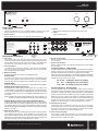
REAR PANEL CONTROLS
6
7
AUTO
9
Connect
Receiver
Here
6. Line 1 Input
This is the secondary input, use Line 2 IN for your main input. Line 1 IN can
be used if a second source is desired and takes over when signal is present
and has at least a 5mV level. When there is no signal, or a signal with less
than 5mV level, the amp switches back to Line 2 IN after a brief delay.
7. Line 2 Input/Output
Line 2 IN should be used as the “primary” or main input for the amplifier.
Connect your receiver or main source to this input. Use Line 2 OUT to pass
Line 2 IN signal to another amplifier.
8. Mode Select Switch
Switches the amplifier from Stereo mode to Bridged mode.
STEREO MODE
If you will be connecting one or two pair of speakers to the amplifier, place
the switch in the “Stereo” position. NOTE: For playing 2 pairs of speakers
(A plus B), make sure each speaker has an impedance of 8 ohms or greater.
11
(+)
RIGHT
( -)
LEFT
(+)
FUSE 4A
13
Figure 2. Rear Panel
10. Speaker Zone A Output
Speaker output terminals for zone A. Minimum impedance: 8 ohm bridged
or 4 ohm stereo.
11. Speaker Zone B Output
Speaker output terminals for zone B. Minimum impedance: 8 ohm bridged
or 4 ohm stereo.
SPEAKER TERMINALS - STEREO MODE
For stereo output connect the speaker’s positive (red) terminal to the amplifier’s
positive (red) terminal, and the speaker’s negative (black) terminal to the
amplifier’s negative (black) terminal for each Right and Left speaker.
NOTE: To prevent sonic degradation in your speaker installation, total speaker
wire resistance should be kept below 0.5 ohms. This table lists recommended
speaker wire gauge versus wire run length.
BRIDGED MODE
When set to “Bridged” mode, the amplifier is a single channel mono amplifier.
50’ or less - 16 Gauge 2-Cond. CL3 Rated
50’ - 150’ - 12 Gauge 2-Cond. CL3 Rated
150’ - 200’ - 10 Gauge 2-Cond. CL3 Rated
BRIDGED MODE- MONO APPLICATION
For bridged mode, playing Right and Left together as mono output, use a
Y cable adapter to connect Right and Left RCA signal to the Right (red) input
at Line 2 IN. Set the MODE switch to BRIDGED and follow the instructions
for bridged speaker connection in the SPEAKER TERMINALS section of
this manual.
SPEAKER TERMINALS - BRIDGED MODE
Place the “MODE” switch in the “BRIDGED” position and use both red
terminals to connect to the speaker. Connect the speaker’s negative (black)
terminal to the amplifier’s left channel positive (red) terminal, and the speaker’s
positive (red) terminal to the amplifier’s right channel positive (red) terminal.
NOTE:The AMP 100 supplies 150W in bridged mode, Please verify that your
speakers are capable of handling such power to avoid possible damage!
BRIDGED MODE- STEREO SOUND USING TWO MONO AMP 100
To play separate Right and Left channel signals with a pair of mono amplifiers,
connect to the source using the Right (red) RCA jacks at Line 2 IN. Connect
the Left RCA cable end to one amp, and the Right RCA cable to the other.
Set both MODE switches to BRIDGED, and follow the instructions for bridged
speaker connection.
9. AUTO ON Select Switch
Power can be turned on and off manually via the switch on the front panel
or automatically by signal sensing. Set it to NORMAL for manual power on/off.
Set to AUTO for signal sensing; the amp will turn on when audio signal is
detected at the inputs. NOTE: The front panel power switch must be in the
ON position (pushed in) for the AUTO ON feature to operate.
13970 SW 72nd Ave. Portland, OR 97223 • 503.914.4688 • www.audiosource.net
NOTE: Only one zone (A or B) can be bridged. Do not attempt to bridge both
A and B speaker terminals! This may result in a lower impedance than the
amplifier is designed for and may damage your amplifier. The minimum
impedance for the total load connected in bridged mode is 8 ohms.
12. Unswitched A/C Terminal
Provides A/C power for additional components. Use only for a single low
power device such as a tuner, CD, DVD, turnable or other non-amplified
electronics. Do not connect another amplifier or receiver. Ensure 400W
max power consumption for any device plugged in here.
13. Power Cord & Fuse Holder
This amplifier is configured for operation at 115V. (North America) A fuse
in the integrated holder provides safety protection from fault conditions.
Replace fuse with 5 x 20mm T4A 250V.
3