1
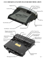
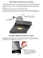
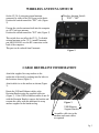
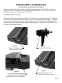
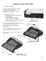
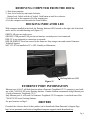
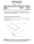
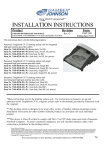
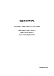
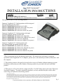
INSTALLATION INSTRUCTIONS
Product
Revision
7160-0318-00 THROUGH 7160-0318-12
PANASONIC TOUGHBOOK CF-31 MAG DOCKING STATION
Rev. F
Form
INST-509
Printing Spec: PS-001
This instruction sheet is for the following products:
Panasonic Toughbook CF-31 docking station with No integrated
high gain antenna pass-thru cables.
Item No. 7160-0318-00 (-P) (Button lock, No RF)
Item No. 7160-0318-04 (-P) (Button lock, No RF, Int. power)
Item No. 7160-0318-07 (-P) (Auto lock, No RF)
Item No. 7160-0318-10 (-P) (Auto lock, No RF, Int. power)
Panasonic Toughbook CF-31 docking station with single
integrated high gain antenna pass-thru cable.
Item No. 7160-0318-01 (-P) (Button lock, Single RF)
Item No. 7160-0318-05 (-P) (Button lock, Single RF, Int. power)
Item No. 7160-0318-08 (-P) (Auto lock, Single RF)
Item No. 7160-0318-11 (-P) (Auto lock, Single RF, Int. power)
Panasonic Toughbook CF-31 docking station with
dual integrated high gain antenna pass-thru cable.
Item No. 7160-0318-02 (-P) (Button lock, Dual RF)
Item No. 7160-0318-06 (-P) (Button lock, Dual RF, Int. power)
Item No. 7160-0318-09 (-P) (Auto lock, Dual RF)
Item No. 7160-0318-12 (-P) (Auto lock, Dual RF, Int. power)
*These instructions are for the docking station only. For instructions on features, set-up and
operation of the Toughbook CF-31 computer, please refer to the manuals provided by Panasonic with
the computer.
** This docking station is designed to be used with a variety of Gamber-Johnson mounting systems.
Installation instructions for other Gamber-Johnson products are provided with each individual
product.
***This device is Class B verified to comply with Part 15 of FCC Rules when used with a Panasonic
Notebook Computer. To assure continued compliance, use only shielded interface cables when
connecting a peripheral to the docking station.
Product Mounting Disclaimer
Gamber-Johnson is not liable under any theory of contract or tort law for any loss, damage, personal injury, special, incidental or consequential damages for personal injury or other damage
of any nature arising directly or indirectly as a result of the improper installation or use of its products in vehicle or any other application. In order to safely install and use Gamber-Johnson
products full consideration of vehicle occupants, vehicle systems (i.e., the location of fuel lines, brakes lines, electrical, drive train or other systems), air-bags and other safety equipment is
required. Gamber-Johnson specifically disclaims any responsibility for the improper use or installation of its products not consistent with the original vehicle manufactures specifications
and recommendations, Gamber-Johnson product instruction sheets, or workmanship standards as endorsed through the Gamber-Johnson Certified Installer Program.
© copyright 2011 Gamber-Johnson, LLC
If you need assistance or have questions, call Gamber-Johnson at 1-800-456-6868
Pg 1
CF-31 DOCKING STATION FEATURE IDENTIFICATION
Alignment Pin
Docking Connector
External Antenna
Connectors
Interlock Pin
Alignment Pin
USB Port
Front Retainer
Docking Indicator
LED
Push Button / Auto Lock
Wireless Antenna Switch
(WWAN Antenna)
DC In
WLAN/GPS Antenna
Connector
WWAN Antenna
Connector
Docking Handle
Serial 2
Serial 1
Video Connection
External Microphone
External Speaker
or Headphones
Ethernet Port #2
Ethernet Port #1
USB Ports
Cable Restraint
Bracket
Kensington Lock Slot
Pg 2
IMPORTANT SAFETY INFORMATION FOR
INSTALLERS
Safety is dependent on the proper installation and servicing of this docking station. It is important to
read and follow all instructions before installing this product.
To properly install a Gamber-Johnson docking station you must have a good understanding of
automotive electrical procedures and systems, along with proficiency in the installation and service of
aftermarket vehicle equipment.
There are no adjustments required at any time of the electrical components within the docking station.
Opening the port replication housing (EXCEPT TO INSTALL THE POWER CABLE) will void the
product warranty.
During Installation:
zDO NOT connect this docking station to the vehicle battery until:
1. ALL other electrical connections are made
2. Mounting of ALL components is complete
3. VERIFICATION that no shorts exist in the entire system
zDO NOT install equipment or route wiring or cords in the deployment path of any air bag.
zWhen drilling into the vehicle, DO make sure that both sides of the surface are
clear of anything that could be damaged.
CAUTION: If wiring is shorted to the frame, high current conductors can cause hazardous sparks
resulting in electrical fires or flying molten metal.
After Installation:
zTest the docking station to ensure that it is working properly.
zFile these instructions in a safe place and refer to them when performing maintenance or
re-installing.
WARNING: Failure to follow all safety precautions and instructions may result in property damage,
serious injury or death.
PRE-INSTALLATION RECOMMENDATIONS
Conduct a "Bench Test"
Gamber-Johnson strongly advises a "bench test" be conducted to verify that all electronic and software
issues are resolved prior to installation:
1. Make sure computer is operational by itself.
2. Insert computer into docking station and verify that the computer is operating in the dock.
3. Interconnect entire assembly and verify start-up of all components, including other
equipment (printers, modems, scanners, etc.).
*Gamber-Johnson recommends positioning of all mounts and equipment in the vehicle prior to the
actual install to verify that mounting locations are safe and practical.
Pg 3
MOUNTING THE DOCKING STATION
Mount docking station to mounting system using the four 1/4-20 UNC mounting holes on the bottom
of the dock. Four 1/4-20 UNC x .50 Button Head Mounting Screws are provided in the hardware bag.
*Recommended torque: 75 in-lbs. Over tightening mounting hardware may damage docking
station.
*Use of hardware longer than 5/8" may damage docking station.
This docking station is designed to be used with a variety of Gamber-Johnson mounting systems.
Installation instructions for other Gamber-Johnson products are provided with each individual product.
(4) 1/4-20 x .50 Button
Head Mounting Screws
Clevis
(Not Included)
SEVERE VIBRATION INSTALLATIONS
Gamber-Johnson recommends the use of optional Side Restraints in severe vibration applications.
Side Restraints and mounting hardware are available seperatly and are assembled to the dock using
four provided #8-32 x .38 flat head screws (Figure 1).
Figure 1
Side Restraints (optional):
Angle as shown and insert into
side cutouts on docking staton.
Secure with prodvided #8-32
flat head screws.
Pg 4
WIRELESS ANTENNA SWITCH
On the CF-30, if using an external antenna,
connected by cable to the WAN port on the dock:
Position the switch toward the "EXT" side (Figure
2).
Wireless Antenna Switch
"EXT" / "INT"
If using the wireless antenna built into the computer
or a PC Card type antenna:
Position the switch toward the "INT" side (Figure 2).
This switch does not affect the CF-31, To disable
external antenna on the CF-31, install Panasonic
part #HS10954505 over the RF connection on the
back of the computer.
This part can be ordered from Panasonic.
Figure 2
CABLE RESTRAINT INFORMATION
Attach the supplied tie wrap anchors to the
underside of the dock by pushing into the holes in
the locations shown (Figure 3).
Attach cable ties to the anchors as shown (Figure
3).
Retain the USB and Ethernet cables at the
Restraint Bracket using the supplied cable ties
(Figure 3). If the USB or Ethernet cables do not fit
with the Restraint Bracket, remove the bracket and
restrain the cables with the additional tie wrap
anchors supplied in the hardware bag.
Figure 3
USB/Ethernet
Support Bracket
Assemble cable ties to the
anchors and route cables
as required.
Pg 5
POWER SUPPLY INFORMATION
(NON INTERNAL POWER SUPPLY MODELS)
Panasonic recommends using a Lind Auto Adapter (Lind part number PA1580-2961) to power the
docking station. It can be ordered from Gamber-Johnson (part number 14103) or directly from Lind
Electronics, Minneapolis, Minnesota (952-927-6303).
Installation of the Power Jack:
Remove the #8-32 screw and the Power Cable Cover on the bottom of the dock (Figure 4). Attach the
Power Cable Pull Strap (located in the hardware bag) to the power jack as shown (Figure 5). Plug the
power jack into the input jack, located on the port replicator circuit board inside the docking station,
and tuck the pull strap into the docking station as shown (Figure 6). Replace the Power Cable Cover
to secure the power jack (Figure 7).
Figure 4
Remove #8-32unc screw
and Power Cable Cover
Figure 6
Insert power jack into mating jack
on port replicator board and tuck
the pull strap into the electrical box.
Figure 5
Power Cable Pull Strap
Figure 7
Replace Power Cable Cover
to hold the power jack in place.
Pg 6
DOCKING THE COMPUTER
1. Shut down the computer.
2. Make sure the sliding door (located on the
on the back of the computer) has
been fully opened, exposing the computer's
docking connector. (Figure 8)
3. Set computer in the dock:
a. Hook the front of the computer on the front
retainer (Figure 9).
b. Lower the back of the computer
onto the Alignment Pins (Figure 9).
c. Lightly press down on the back of the computer
to ensure it is fully seated.
4. Pull the docking handle towards the left side of the
dock until the latch catches (Figure 10).
(The Push Button latch can be locked for
added security)
Figure 8
Sliding Door
Docking Connector
Alignment Pins
5. Boot the computer. If the dock is powered, the
computer is powered and ready for use.
*Docking station will operate with computer screen
opened or closed.
Front Retainer.
Figure 9
Docking handle in
"UNDOCKED" position
Figure 10
Docking handle in
"DOCKED" position
Pg 7
REMOVING COMPUTER FROM THE DOCK
1. Shut down computer.
2. Auto Lock: Insert key and rotate clockwise.
Button Lock: Unlock with key if locked. Push button in until lever releases.
3. Lift the back of the computer off of the locating pins.
4. Lift the computer out from under the Front Retainer.
DOCKING INDICATOR LED
With computer installed in the dock, the Docking Indicator LED, located on the right side of the dock,
can be used as a troubleshooting tool (Figure 11).
GREEN: All ports are ready to use.
ORANGE: USB port and LAN port do not function, external power is not connected.
RED: PC is not supported or connection is not made.
RED (BLINKING): Error has occured in the firmware. Stop using at once and contact Panasonic
Technical Support.
NOT LIT: PC not installed or PC is OFF, Standby or Hibernation.
Docking Indicator LED
Figure 11
ETHERNET PORT INFORMATION
Ethernet ports #1 & #2 will both function when a Panasonic Toughbook CF-31 computer is used with
one of the 7160-0318-XX series Docking Stations. Gamber-Johnson recommends using Ethernet port
#2 with a Panasonic Toughbook CF-31.
Only Ethernet port #1 will work if a Panasonic Toughbook CF-30 computer is used with one of the
7160-0318-XX series Docking Stations.
See port locations on Page 2.
DRIVERS
If needed, the software driver for this product can be downloaded from Panasonic's Support Page:
http://www.panasonic.com/business/toughbook/computer-support-search-downloads.asp
Pg 8