1
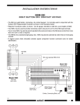
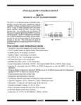
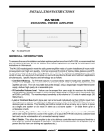
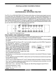
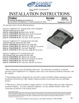
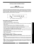
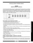
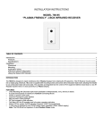
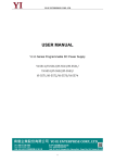
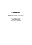
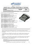
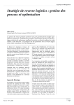
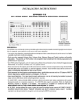
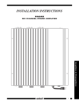
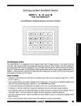
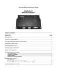
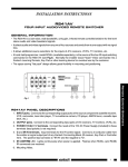
INSTALLATION INSTRUCTIONS RP41AV REMOTE PREAMP GENERAL INFORMATION The RP41AV, Fig. 1, is a fully functional infrared remote controlled audio/video preamp. Volume, Bass, Treble, Balance and Mute functions, in addition to A/V input switching, provide all the functions needed for multi-room systems. It features a low noise, low distortion design with high headroom capability, for highest audio and baseband video performance. The RP41AV has the following features and functions: • The model RC68+ (and RC68) handheld programmer (available separately), is the source of all the IR (infrared) commands necessary to operate the RP41AV (see Fig. 2). Normally the installer would "teach" these commands into a Xantech Learning Remote, Key Pad or other learning device for use by the customer. • Audio and video signals connected to four separate line level A/V inputs, labeled 1, 2, 3, and 4, may be accessed in any order by IR commands. • Separate Volume (Up/Down), Balance (Left/Right), Bass and Treble controls feature continuous adjustment in 2 dB steps, in either direction, all IR controlled. • Balance, Bass &Treble controls have a Flat function for instant return to flat response from any previous setting. • Separate Mute On & Mute Off functions ensure positive mute command execution without knowing status. This is helpful in remote rooms when all adjustments are made “blind” without any visual aids for status. • IR control input port connects to the emitter output of Xantech devices, allowing remote control from keypads, IR receivers, connecting blocks, etc. • The space saving “flat pack” design allows great flexibility in mounting and positioning. 1 2 3 4 RP41AV VIDEO PANEL DESCRIPTIONS 1. INPUT jacks. Connect to the corresponding output jacks of source components (satellite receiver, VCR, camcorder, laser disc player, TV surveillance camera, CD player, AM/ FM tuner, cassette tape deck, etc.). REMOTE PREAMP IR CONFIRM ® AUDIO LEFT AUDIO RIGHT POWER 15VAC V V G IR IN INPUT OUTPUT 1 2 3 4 5 6 Fig. 1 RP411AV Panel Items 2. OUTPUT jacks. Connect the VIDEO output jack to the corresponding Video input jacks of AV receivers, TV monitors, VCRs, etc. Connect the AUDIO LEFT and AUDIO RIGHT output jacks to the corresponding input jacks on a main power amplifier. Since these are low-impedance outputs, you may connect up to 5 power amplifiers to one RP41AV prodvided such amplifiers have input impedances of 22k Ohms or more. Use "Y" connectors or other paralleling means. 1 Amplifiers & Preamplifiers • Tone controls allow individual "EQ" of each zone when using multiple RP41AV's in multi-zone installations. 4. G S terminals. Input terminals for the IR control signal. Connect a 2-conductor cable from the emitter or signal output port of any Xantech Connecting Block, IR receiver, Key Pad, or Controller here. The positive lead connects to "S" and the negative to "G". 5. IR CONFIRM LED. Lights when power is applied and flashes when IR commands are received. 6. Mounting Holes. RC68+ PROGRAMMER / REMOTE CONTROL The RC68+ (and the RC68) programmer (available separately) contains all the commands necessary to operate the RP41AV. • You will need it to program universal learning devices such as the Xantech URC type learning remote, the Xantech Smart Pads, the 590 Programmable Controller, the 710 Fone Link, etc., with commands that operate the RP41AV. • NOTE: The RC68+ will operate several other Xantech models as well, such as the RS41AV, ZPR68, MIRV1, RAT1, etc. Therefore, only the button descriptions that apply to the operation of the RP41AV are listed below. All others should be ignored. • While the RC68+ will operate as a separate remote control, it is highly recommended it not be given to the final user for the following reasons: Since it permits code group changes , the user may inadvertently alter the installer configurations. • Also, since the user will require IR commands from other brands of equipment to control the total system, in addition to those of the RP41AV, all commands should be consolidated into one learning device, for ease of use. RC68+ BUTTON DESCRIPTIONS 1. IR Emitter Lens 1 3. INPUT Select buttons. Press buttons 1 through 4 to individually select up to 4 audio/video sources connected to the RP41AV. 5. VOLUME Up/Down buttons. When pressed, volume will increase and decrease in 2 dB steps between 0 dB and -80 dB. When buttons are held down, the volume level will change continuously. 6. MUTE ON / OFF buttons. Separate On / Off buttons give positive mute commands without knowing what the status is. This is very helpful in a remote room when all adjustments are made “blind” without any visual aids for status. NOTE: Mute is released (turned off) when a VOLUME, INPUT, BALANCE, BASS or TREBLE button is pressed, in addition to MUTE OFF. 9. BALANCE buttons. When the BALANCE "arrow" buttons are pressed, the audio output will move to the left or right in 2 dB steps with each left or right press. (No change will occur if they are held down continuously). 18 17 2 A B C ADJ-OFF 80 48 10 90 1 2 3 4 00 C0 5 16 15 40 50 6 INPUT 7 A0 D0 A 01 41 3 8 30 B0 21 61 4 GLOBAL 20 E0 70 F0 TREBLE BASS Z-ADJ VOL 60 88 18 98 09 08 A8 29 5 MUTE 14 13 12 B8 OFF 28 E8 78 F8 E-FLAT LAST MAX-V TRIM 68 C8 58 D8 OFF 11 38 ON 6 69 7 49 8 C-BAL E1 89 C9 A9 E9 71 19 59 39 79 F1 99 D9 B9 F9 9 10 RC68+ Fig. 2 10. Balance "Center" button. This button, when pressed (identified by "C_BAL"), will instantly return the balance to the center position from any previous setting. 14. TREBLE & BASS control buttons. When the "arrow" buttons are pressed, the treble and bass response can be increased or decreased from 0 dB to ± 12 dB in 2 dB steps with each up or down press. (No change will occur if they are held down continuously). In "multi-zone" systems, you can use these controls to "EQ" (equalize) the sound for each room's acoustic differences. 2 RP41AV 15. Treble & Bass "N-Flat" buttons. These buttons, when pressed (identified by a "—" mark), will instantly return the treble and bass to their electrical flat settings from any previously adjusted values. 17. Code Group Numbers. If more than one RP41AV is used in an IR controlled system, or is included with other Xantech products that respond to RC68+ commands, different code groups can be assigned to avoid mutual interaction. NOTE: When shipped from the factory, the RP41AV is set to code group 40. Be sure to set the RC68+ to the same code! Refer to the RC68+ instructions for code group setting procedures. TYPICAL RP41AV SINGLE ZONE SYSTEM The following diagram shows a typical single-zone 4-room system utilizing the RP41AV. In this case, you would program the Smart PadTM, plus a learning remote (such as Xantech URC types) with the commands from the RC68+ remote, in addition to all the other source component remote commands, to operate the entire system from any room. For AC power management, refer to the Model 680-10 Installation Instructions. MAIN ROOM Left Speaker Right Speaker TV Video IN MONITOR Stereo Power Amp 490-30 L Micro Link™ IR Receiver (Cabinet Mounted) SAT Receiver V R Audio "Y" Connectors 1 L R 2 3 L 4 R DVD Player RP41AV VIDEO REMOTE PREAMP IR CONFIRM ® AUDIO LEFT AUDIO RIGHT 283M POWER 15VAC V V G IR IN INPUT RP41AV VCR V 283M Blink-IR™ Mouse Emitter (4) L R RCA patch cords AM/FM Tuner Amplifiers & Preamplifiers White Striped Side 2-Conductor Mini Plug to Stripped Ends (use 6015900) Power Supply (included) Remote Preamp L R 283M OUTPUT 283M L 791-44 R Stereo Power Amp 791-44 IR IN S TAT U S +12 VDC HIGH IR OUT GND Amplified Connecting Block EMITTERS AMPLIFIED CONNECTING BLOCK ® IR RCVR 12 VDC 781RG Power Supply 3-Conductor Cable (Home Runs) To 120 VAC (unswitched) Home Run Speaker Leads XANTECH S-62/64/66 Wall Speakers L R 780-10 "J" Box IR Receiver 760-00 Match Maker™ Vol. Control ROOM 2 L 480-00 R L 760-00 Dinky Link ™ IR Receiver Match Maker™ Vol. Control ROOM 3 Smart Pad™ R 760-00 Match Maker™ Vol. Control ROOM 4 Fig. 3 A typical single zone system RP41AV 3 A MULTI-ZONE SYSTEM The following diagram illustrates a typical Multi-Zone system, using the RP41AV. 1. For simplicity, only 4 zones are shown ... many more could be added using the Xantech 796-20 Zone Expander and more RP41AV's. 2. Using an RP41AV plus a basic power amplifier for each zone, every room in the house can have individual source selection, volume control and room EQ (with the tone controls) at moderate cost. 3. The audio and video connections from the source components to each RP41AV (not shown), should be made through distribution amps (such as the Xantech AV-61) to prevent distortion that may be caused by the loading effects of multiple RP41AV's. Refer to the AV-61 Installation Instructions for more details. 4. For AC power management, refer to the 680-10 and Gatekeep-IRTM Installation Instructions. MAIN ROOM - ZONE 1 Left Speaker TV Right Speaker Video IN MONITOR 490-00 Micro Link™ IR Receiver (Cabinet Mounted) Stereo Power Amp R To distribution amplifiers, for each source. Repeat for each zone. See text, item 3, this page. Common Sources 1 2 3 L 4 RP41AV VIDEO REMOTE PREAMP ® AUDIO LEFT Zone 1 RP41AV OUTPUT ANT. or Cable Modulator (3-Input) 1 2 3 RP41AV VIDEO REMOTE PREAMP ® AUDIO LEFT AUDIO RIGHT INPUT RF Amp IR CONFIRM RP41AV POWER 15VAC V V G IR IN OUTPUT Stereo Power Amp 1 2 3 RP41AV VIDEO Combiner REMOTE PREAMP ® AUDIO LEFT Z1 RP41AV OUTPUT Z2 Z3 Stereo Power Amp Z4 283M Blink-IR™ Mouse Emitter (4) 1 2 3 200-00 2-Way Splitter Zone 4 4 RP41AV VIDEO INPUT REMOTE PREAMP IR CONFIRM AUDIO LEFT ® AUDIO RIGHT POWER 15VAC V V G IR IN RP41AV OUTPUT Stereo Power Amp RG-6 Coax 782-00 Power Supply IR ZONE CONNECTIONS INPUT IR CONFIRM POWER 15VAC V V G IR IN AUDIO RIGHT AM/FM Tuner Zone 3 4 ZONE EMITTERS DVD Player Zone 2 4 IR Zone Controller ZONE CONTROLLER VCR 795-20 COMMON EMITTERS White Striped Side 795-20 Power Supply (included) INPUT 4 3 2 1 10 9 8 7 6 5 4 3 2 1 A B A B A B A B 12V SAT Receiver IR CONFIRM POWER 15VAC V V G IR IN AUDIO RIGHT To 120 V AC (unswitched) Home Run 3 Conductor Cables (unshielded OK) Home Run all Speaker Leads XANTECH S-62/64/66 Wall Speakers L R L RF IN L R R RF IN TV TV MONITOR MONITOR 480-00 780-10 "J" Box IR Receiver ZONE 2 Dinky Link™ IR Receiver Smart Pad™ ZONE 3 780-10 "J" Box IR Receiver ZONE 4 Fig. 4 A multi-zone 4-room system 4 RP41AV RP41AV SPECIFICATIONS 6-26-00 RP41AV 5 Amplifiers & Preamplifiers Gain (@ max VC): . . . . . . . . . . . . . . . . . . . . . . . . . . . . . . . Unity Input Overload: . . . . . . . . . . . . . . . . . . 4.5 V RMS (@ max VC) Input Impedance: . . . . . . . . . . . . . . . . . > 40 k Ohms (ea. input) Output Impedance: . . . . . . . . . . . . . . . . . . . . . . . . 470 Ohms (allows output to be paralleled for mono, if needed) Volume Attenuation: . . . . . . . . . . . . . . . . . . . . . . . . . . . . -80 dB Signal to Noise: . . . . . . . . . . . . . . . . . . . . . . 100 dB (re 2V out) THD: (VC -10 dB) . . . . . . . . . . . . . . . 0.01% at 2.0 V input level Channel Separation: . . . . . . . . . . . . . . . . . . . > 75 dB @ 1 kHz Freq. Response: . . . . . . . . . . . . . . . . . . . 20Hz-20kHz +/- 1 dB Bass Range: . . . . . . . . . . . . . . . . . . . .+/- 12 dB (in 2 dB steps) Treble Range: . . . . . . . . . . . . . . . . . . +/- 12 dB (in 2 dB steps) Video IN/OUT Impedance: . . . . . . . . . . . . . . . . . . . . .75 Ohms. Video Insertion Loss: . . . . . . . . . . . . . . 50 Hz - 10 mHz < 1 dB. Video Out-IN Isolation: . . . . . . . . . . . . 50 Hz - 10 mHz > 55 dB. A/V Inputs/Outputs: . . . . . . . . . . . . . . . . RCA type phono jacks IR Code Group: . . . . . . . . . . . . . . . . . . . . . . 40 (factory preset) Power Requirements: . . . . . . . . . . . . . . . . 15 VAC @ 300 mA. (Power supply included) Power and IR Inputs: . . . . . . . . . . . . . 4-terminal screw terminal plug-in connector Dimensions: . . . . . . . . . . . . . . . . . . .10" W x 3" D x 1 3/8" H 254mm x 73mm x 35mm INSTALLATION INSTRUCTIONS 283M DESCRIPTION The 283M Blink-IR Mouse Emitter contains a small Infrared LED housed in a miniature, mouse shaped, black appearing, injection molded plastic shell. Unlike other emitters, the 283M emits visible red light in addition to IR (infrared) control signals when activated by IR commands sent to it by IR receivers or other Xantech controllers. The 283M is designed to be installed directly on the IR sensor window of the controlled device. Model 283M Blink-IR™ Mouse Emitter Assembly 3.5mm mono mini plug (+) NOTE: White striped side is positive (+) Side View 1/4" Top View 5/16" (–) 7 FT Fig. 1 3 FT 9/16" INSTALLATION ATTACHING THE EMITTERS TO IR SENSOR WINDOWS • Each emitter has a clear adhesive layer on the bottom flat surface of the shell. The rounded side faces the user and emits visible red light when a command is sent (Fig. 2). • Simply peel off the adhesive cover and affix the emitter to the center of the IR sensor window on the controlled component's front panel. IR & Red Light Output Emitter Shell Fig. 2 Mini-wire lead IR & Red Light Output (Component Side) Clear adhesive layer. (Replace, if necessary, with a short piece of the 2-sided tape supplied). • In some cases it may be difficult to find the location of the IR sensor on the component. Consult the owner's manual of the unit, or the manufacturer, for the exact IR sensor window location. • Double-sided adhesive tape is included. If you move the emitter to a different component, use this tape to replace the current adhesive layer for best adhesion. • The shell, though dark in appearance, is transparent to infrared light, allowing commands from a handheld remote control to pass through it. This permits direct control of the equipment from a handheld remote as well as from the 283M. 1 Emitters & Blasters BLINK-IR™ MOUSE EMITTER