1
ViewPoint
Wireless Touch Panels (Wave Server)
Instruction Manual
ViewPoint Wireless Touch Panels and
Accessories
Limited Warranty and Disclaimer
AMX Inc. warrants its products to be free from defects in material and
workmanship under normal use for a period of three years from date of purchase
from AMX Inc., with the following exceptions. Electroluminescent and LCD
control panels are warranted for a period of three years, except for the display
and touch overlay components which are warranted for a period of one year.
Disk drive mechanisms, pan/tilt heads, power supplies, modifications, MX
Series products, and KC Series products are warranted for a period of one year.
Unless otherwise specified, OEM and custom products are covered for a period
of one year. AMX, Incorporated software products are warranted for a period of
90 days. Batteries and incandescent lamps are not covered.
This warranty extends to products purchased directly from AMX Incorporated
or an authorized AMX Inc. dealer. Consumers should inquire from selling dealer
as to the nature and extent of the dealer’s warranty, if any.
AMX Inc. is not liable for any damages caused by its products or for the failure of
its products to perform, including any lost profits, lost savings, incidental
damages, or consequential damages. AMX Inc. is not liable for any claim made
by a third party or made by you for a third party.
This limitation of liability applies whether damages are sought, or a claim is
made, under this warranty or as a tort claim (including negligence and strict
product liability), a contract claim, or any other claim. This limitation of liability
cannot be waived or amended by any person. This limitation of liability will be
effective even if AMX Inc. or an authorized representative of AMX Inc. has been
advised of the possibility of any such damages. This limitation of liability,
however, will not apply to claims for personal injury.
Some states do not allow a limitation of how long an implied warranty lasts.
Some states do not allow the limitation or exclusion of incidental or
consequential damages for consumer products. In such states, the limitation or
exclusion of the Limited Warranty may not apply to you. This Limited Warranty
gives you specific legal rights. You may also have other rights that may vary
from state to state. You are advised to consult applicable state laws for full
determination of your rights.
EXCEPT AS EXPRESSLY SET FORTH IN THIS WARRANTY, AMX INC. MAKES NO OTHER
WARRANTIES, EXPRESS OR IMPLIED, INCLUDING ANY IMPLIED WARRANTIES OF
MERCHANTABILITY OR FITNESS FOR A PARTICULAR PURPOSE. AMX Inc. EXPRESSLY
DISCLAIMS ALL WARRANTIES NOT STATED IN THIS LIMITED WARRANTY. ANY IMPLIED
WARRANTIES THAT MAY BE IMPOSED BY LAW ARE LIMITED TO THE TERMS OF THIS
LIMITED WARRANTY.
Table of Contents
Introduction .............................................................................. 1
Overview
1
ViewPoint Models
1
Features
2
Related Instruction Manuals
2
What’s in this Manual
3
What’s New
3
Connections, Cleaning, and Charging ................................... 5
Overview
5
Application
5
Connectors
6
Multiple ViewPoints in an Installation
6
Cleaning the Touch Overlay
7
ViewPoint Rechargeable Battery
7
Power Supply
8
VPA-CHG FastCycle Battery Charger for VPA-BP
8
ViewPort Docking Station
10
Battery Charging
11
Touch Panel Basics ................................................................. 13
Overview
13
Touch Panel Pages
14
Standard Buttons
14
General Buttons
14
AXB-PT30 PosiTrack 30 Camera Controller
Selection buttons
15
Information buttons
15
Adjustment buttons
15
Keypad buttons
15
Decision buttons
16
Status buttons
16
Operation bars
16
Touch to Continue buttons
17
Table of Contents
i
Designing Touch Panel Pages................................................. 19
Overview
19
Activating the Edit button
19
Creating a Page
23
Adding a page
23
Setting the page color
24
Creating a Button
25
Adding a button
25
Resizing a button
26
Button Properties
27
Setting the button properties
27
Setting the button type
28
Setting the button border
28
Setting the channel code
29
Setting the variable text code
30
Setting the page flip
31
Setting the button colors for channel-off
conditions
32
Adding text to a button
33
Adding an icon to a button
34
Adding a bitmap to a button
35
Using TPDesign3 to Download Bitmaps, Icons,
and Fonts
37
Button Properties for External Pushbuttons
39
Creating an IR Macro Button
39
Pulse command
40
Wait command
41
What happens when the example macro
executes
43
Creating a Joystick
44
Adding a joystick to a page
44
Setting the joystick properties
45
Setting the channel code
46
Setting the level code
47
Setting the joystick colors/shades for
channel-off conditions
Creating a Bargraph
ii
Table of Contents
47
48
Adding a bargraph to a page
49
Setting the bargraph properties
50
Setting the channel code
50
Setting the level code
51
AXB-PT30 PosiTrack 30 Camera Controller
Setting the bargraph colors/shades for
channel-off conditions
51
Linking the New Page to the Main Page
52
Exiting Edit Mode
55
Touch Panel Program Reference ............................................. 59
Overview
59
Setup Page
59
Beep
60
Display timer
60
Set time and date
61
Double beep
62
AXlink, output resolution, vX.XX, and
serial number
62
Setting brightness
62
Protected setup
63
Show palette
64
Wireless status (optional WAV-PK)
64
Wireless status (optional SMT-PK)
66
Wireless settings for VPT-CP and VPT-GS
67
Wireless Status for VPW-CP and VPW-GS
68
Wave-Pak not locked
69
Module version
69
Server version
69
RSSI
69
Network Eff.
69
Device Eff.
69
Device range
70
Server devices
70
Protected Setup Page
70
AXB-PT30 PosiTrack 30 Camera Controller
Baud
71
Device base
71
Device used
72
Setup password
72
Power up page
72
Wake up message
73
Auto assign
73
Page password
74
Calibrate
74
Power up message
74
System page
75
Table of Contents
iii
Editor
78
Page tracking
79
Sleep message
79
Function show
79
Wireless Settings for VPW-CP and VPW-GS
Wave-Pak not locked
81
RSSI
81
Network Eff.
81
Device Eff.
81
Device range
81
Server devices
81
Wireless settings (optional SMT-PKM)
81
Edit button
82
Edit Bar - Button Menu Options
Table of Contents
84
Add
84
Copy image
85
Move
85
Resize
85
Delete
86
Text/image
86
Properties
90
Save
98
Paste
98
Save default
98
Set default
99
Put on top
99
Properties Page - Button Types
iv
80
99
General
100
Joystick
104
Vertical Bargraph
106
Horizontal Bargraph
107
Brightness
109
Time
111
Date
112
Keypad
113
Keyboard
114
Setup
114
Video Setup
115
Video Window
116
Video Joystick
116
AXB-PT30 PosiTrack 30 Camera Controller
RGB Setup
118
Protected
119
Properties Page - External Buttons
120
External buttons
121
Setting external button properties
123
Page Menu Options
124
Add
124
Copy
125
Rename
126
Delete
126
Page color
126
Go to
127
Popup on
127
Popup off
128
Move edit
129
Snap grid
129
Edit Bar - Quit Editor option
130
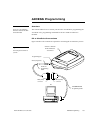
AXCESS Programming ............................................................. 133
Overview
133
PC to ViewPoint Connections
133
Programming the ViewPoint
134
AXCESS Programming Changes
134
System Send_Commands
135
Gray Scale and Programming Numbers
141
Colors/Shades of Gray and Programming Numbers 142
Font Styles and Programming Numbers
142
Border Styles and Programming Numbers
142
Shorthand Send Commands
143
Color/Gray Scale Send_Commands
148
Variable Text Send Commands
151
Shorthand Variable Text Commands
153
Buttons String Commands
157
Button Macro Commands
158
Loading Infrared (IR) Files........................................................ 161
Overview
161
IRLIBX
161
Loading an IR File
163
IR Memory Check
167
AXB-PT30 PosiTrack 30 Camera Controller
Table of Contents
v
Upgrading the Firmware .......................................................... 169
Overview
169
Configuration
170
Downloading the Firmware
170
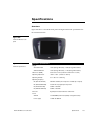
Specifications .......................................................................... 173
Overview
173
VPA-BP ViewPoint Rechargeable Battery
175
VPA-CHG Fast-Cycle Battery Charger for VPA-BP
176
ViewPort Docking Station
177
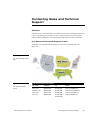
Contacting Sales and Technical Support................................ 179
Overview
179
U.S. Sales and Technical Support Teams
179
AMX International Offices
180
Technical Support
180
Index......................................................................................... 183
vi
Table of Contents
AXB-PT30 PosiTrack 30 Camera Controller
Introduction
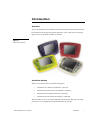
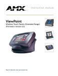
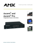
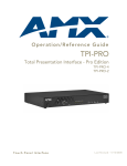
Overview
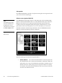
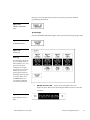
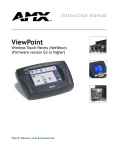
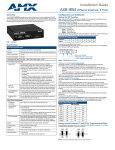
The ViewPoint Wireless Touch Panels and ViewPoint WAVE Touch Panels are handheld, liquid crystal display (LCD) panels that allow you to control devices remotely.
Figure 1 shows some of the available ViewPoints.
Figure 1
ViewPoint touch panels
ViewPoint Models
There are four models of the ViewPoint touch panels:
•
ViewPoint Color Wireless Touch Panel - (VPT-CP)
•
ViewPoint Grayscale Wireless Touch Panel - (VPT-GS)
•
ViewPoint Color WAVE Touch Panel - (VPW-CP)
•
ViewPoint Grayscale WAVE Touch Panel - (VPW-GS)
The VPT panels are one-way infrared (IR) and radio frequency (RF) only. The VPW
panels are two-way digital Spread Spectrum RF and one-way IR.
ViewPoint Wireless Touch Panels
Introduction
1
Features
The other features of the ViewPoint touch panels are:
•
All panels have 6-inch diagonal (153.9 mm), 320 x 240 (HV) pixel screens
•
VPW-CP has a 256 color passive-matrix LCD screen
•
VPW-GS has a 16-shade grayscale LCD screen
•
Four external programmable push buttons
•
Programmable firmware via programming port connection
•
Programming port for uploading/downloading touch panel data
•
Panel programming, pages, and drawings are uploaded and downloaded
using TPDesign (Windows®) 16-bit or TPDesign3 (Windows) 32-bit touch
panel design programs
•
One-way RF or IR transmission (VPT-CP/VPT-GS only)
•
Two-way digital spread spectrum RF (VPW-CP/VPW-GS only)
•
Onboard battery-charging circuitry
Note
•
Unicode® character support for far-eastern languages such as Chinese
Characters for Middle Eastern
•
Hand-held or desktop usage
•
Battery life of 6 continuous hours with full back-lighting (VPT-CP/VPT-GS)
•
Battery life of 4 continuous hours (VPW-CP/VPW-GS)
Note
TPDesign3 is used to convert
G2 or lower panel pages into
G3 firmware compatible
pages.
languages such as Arabic are
not supported within the
Unicode fonts because they
are bi-directional. Buttons with
Unicode fonts can only be
created and edited using
TPDesign3 Touch Panel
Design Program.
2
Introduction
Related Instruction Manuals
These instruction manuals contain additional information that relates to the Color
Passive-Matrix mini-touch panels.
•
TPDesign3 Touch Panel Program
•
WAVE 2-Way Wireless Accessories and Adapters for Touch Panels
•
AXCESS Programming Language
•
OpenAXCESS Configuration and Diagnostic Program
•
Color Passive-Matrix LCD Mini-Touch Panels (Firmware version G3 or
higher)
•
Color Passive-Matrix LCD Touch Panel (Firmware version G3 or higher)
ViewPoint Wireless Touch Panels
•
PowerTilt and PowerTouch Panels (Firmware version G3 or higher)
What’s in this Manual
This manual contains the following sections:
•
Installation
Contains cabling, connections, and connectors as well as
cleaning of the touch panel overlay, power supply, and battery information.
•
Touch Panel Basics
Contains descriptions and illustration examples of
touch panel pages.
•
Touch Panel Program Reference
Describes touch panel operations,
flowcharts, and button options.
•
Designing a Touch Panel Page
•
Explains how to connect the ViewPoint to your PC
for ViewPoint firmware upgrade using SOFTROM.
•
Contains step-by-step instructions to
create a touch panel page, button, joystick, bargraph, and set a page
color/shade.
Firmware Upgrade
Specifications
Describes the physical and operating characteristics of
the touch panels.
•
Identifies contact
information for technical support and technical publications, including
phone numbers, e-mail addresses, and Internet locations.
Contacting Sales and Technical Support
What’s New
Additions and revisions to this release of the manual include:
•
Added ViewPort Docking Station and instructions for creating an IR macro
button
•
Added and updated graphics
Revisions are identified with vertical margin bars on the outside margin, as shown
adjacent to this paragraph
ViewPoint Wireless Touch Panels
Introduction
3
4
Introduction
ViewPoint Wireless Touch Panels
Connections, Cleaning, and
Charging
Overview
The ViewPoint Wireless Touch Panels do not require hardware installation. This
section describes how to connect, clean, and charge the ViewPoint panels.
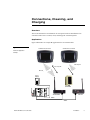
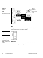
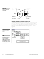
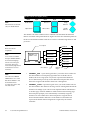
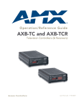
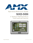
Application
Figure 2 illustrates an example RF application for ViewPoint models
Figure 2
VeiwPoint Touch Panel
VeiwPoint Touch Panel
ViewPoint application
example
One-way IR
Two-way RF
One-way IR
Power
Supply
AXR-IRSM
AXR-RF
AXR-WAVES
Card Frame
AXlink
AXlink
ViewPoint Wireless Touch Panels
Installation
5
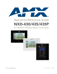
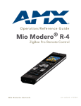
Connectors
All ViewPoints have two connectors, as shown in Figure 3. The power jack is for
connecting an external 12 VDC power supply for ViewPoint operation and charging.
The programming jack is a three-wire, 2.5 mm stereo jack. The required cable and
power supply comes furnished with the ViewPoint.
Figure 3
ViewPoint connectors
Power jack
Programming jack
Stereo plug male
Male DB9
ViewPoint to PC
programming
cable
Cable FG10-517 to
cable FG10727 to your
PC's RS-232
Multiple ViewPoints in an Installation
Note
RF operating frequencies
cannot be user-adjusted.
Operating frequencies must
be factory-set.
6
Installation
The ViewPoint transmits data via RF or IR. The VPT-CP and VPT-GS ViewPoint
Wireless Touch Panels are shipped to operate on a standard frequency of 418 MHz
RF and user-selectable 38 KHz or 455 KHz IR frequencies. The ViewPoints can be
ordered for different RF operating frequencies that must be set when the unit is
manufactured.
ViewPoint Wireless Touch Panels l
Note
The 2-way ViewPoints do not
support AMX IR codes (38
KHz and 455 KHz) but do
support other manufacturers
IR codes. The 1-way
ViewPoints support all IR
codes.
The VPW-CP/VPW-GS operates on 2.4 GHz for two-way RF communications with
the AXR-WAVES Server. It also provides one-way IR using other manufacturers IR
codes.
If you plan to use multiple one-way ViewPoints within the same locals, it is strongly
recommended that each unit be ordered for operation on different RF frequencies.
This will prevent erroneous data being received by the respective AXCESS Central
Controller.
Cleaning the Touch Overlay
You should clean the touch screen overlay after each day’s use. Materials required
are:
•
Two clean, soft texture cotton cloths
•
Spray bottle of cleaning solution consisting of 50% isopropyl alcohol and
50% water.
1. Turn the ViewPoint off.
2. Spray a small amount of the cleaning solution onto one of the cloths.
3. Clean the touch panel overlay with the damp cloth.
4. Wipe the touch panel overlay with the dry cloth.
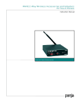
ViewPoint Rechargeable Battery
The ViewPoint requires use of a VPA-BP ViewPoint Rechargeable Battery. Figure 4
shows the VPA-BP and placement in the ViewPoint.
ViewPoint Wireless Touch Panels
Installation
7
Figure 4
VPA-BP ViewPoint
Rear battery cover
Rechargeable Battery
placement
Battery
Touch panel
(rear view)
Power Supply
Note
A 220 VAC power supply is
also available.
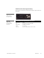
ViewPoints are furnished with a modular wart type Power Supply (Figure 5), which
requires an input of 110 VAC and provides an output of 12 VDC at 1500 mA. The
power supply can be used separately from the VPA-CHG to operate the ViewPoint.
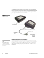
VPA-CHG FastCycle Battery Charger for VPA-BP
The VPA-CHG FastCycle Battery Charger for VPA-BP includes a Power Supply as
shown in Figure 5. The power supply can be used for primary power or charging of
the VPA-BP ViewPoint Rechargeable Battery. The power supply barrel connector
plugs into the side of the ViewPoint.
When charging the VPA-BP, if the battery is inserted incorrectly (backward) into the
charger, a buzzer will sound. While the battery is charging, the red LED lights. When
the battery is fully charged, the green LED lights. If there is no battery in the charger,
neither of the LEDs light up.
8
Installation
ViewPoint Wireless Touch Panels l
Figure 5
VPA-CHG (power supply and
VPT-CP Fast-Cycle Battery
Charger for VPA-BP)
12 VDC Power
Supply
Green LED
indicates battery is
charged
VPA-CHG Fast
Cycle battery
charger
Red LED indicates
charging
Charging pins
ViewPoint Wireless Touch Panels
Power supply
connection
Installation
9
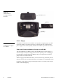
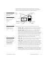
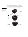
ViewPort Docking Station
The ViewPort Docking Station (Figure 6) provides a built-in battery charger and an
angled desk docking station to cradle your ViewPoint touch panel. When a
ViewPoint is placed in the docking station's cradle, the ViewPoint makes contact with
the charging pins and the docking station then supplies power.
When a touch panel is not cradled on the docking station, a battery can be charged
when placed within the charging compartment. When a touch panel is cradled on the
docking station, all power is fed to the touch panel. A battery that was charging will
no longer be supplied with power until the ViewPoint is removed from the docking
station's cradle.
Figure 6
ViewPort Docking Station
Docking Station
Charging
compartment
Green LED
Red LED
Charging pins
Yellow LED
10
Installation
ViewPoint Wireless Touch Panels l
Battery Charging
Note
When inserting or removing a
battery, insert or remove the
battery slowly to avoid false
indications on the LEDs.
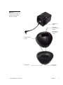
When a ViewPoint touch panel is not cradled on the docking station, an optional
extra battery can be placed in the charging compartment. The optional battery is fully
charged in four hours when the optional power supply is plugged-in to the rear of
the docking station (Figure 7). The ViewPort Docking Station provides tricklecharging of the battery inside the ViewPoint when the ViewPoint is cradled in the
ViewPort.
Figure 7
Rear view
Power supply
connector
Rear view
Retaining ears
(tabs)
Status LEDs (Figure 6) are located on the bottom front of the docking station. There
are three LEDs; yellow indicates a ViewPoint connection to the docking station; red
shows a battery being charged in the charging compartment; green indicates that the
battery in the charging compartment is fully charged.
ViewPoint Wireless Touch Panels
Installation
11
12
Installation
ViewPoint Wireless Touch Panels l
Touch Panel Basics
Note
Refer to the TPDesign3
Instruction Manual for detailed
Touch Panel design
information or to the
ViewPoint VPXpress System
Design/Programming
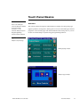
Overview
This section contains descriptions and illustration examples of Touch panel pages
(Figure 8), buttons, message bars, and keypads. You can use the TPDesign3 software
program to create custom pages and download them to the touch panel. Or you can
use the ViewPoint VPXpress System Design/Programming Software.
Software Instruction Manual
Figure 8
Sample touch panel page
TPDesign3 page example
VPXpress page example
ViewPoint Wireless Touch Panels
Touch Panel Basics
13
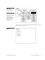
Touch Panel Pages
You can download objects like buttons and drawings to a touch panel page. The
number of objects depends on the type and quantity of external devices you want to
control with the touch panel and AXCESS Control System. When you create multiple
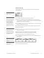
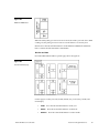
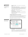
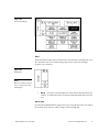
pages, you must link them with buttons. Figure 9 shows how five touch panel pages
are linked to the Main page. Note that each page contains one button that goes to the
next page, and one that goes to the previous page.
Figure 9
Touch Panel pages with
Setup
Page
Page 1
Main Page
linked buttons
Page 2
Main
Page 1
Page 3
Page 1
Page 2
Page 4
Page 2
Page 3
Page 5
Page 3
Page 4
Main
Page 4
Page 5
Standard Buttons
Standard buttons types are rectangles, rectangle variations, and other geometric
shapes that you can create with the touch panel editor. Buttons are set with
attributes, which means there is feedback for the Central Controller when you touch
the button.
General Buttons
General buttons are part of the mini-touch panel program and cannot be changed.
You use general buttons to specify panel communication parameters and create or
revise pages. Button examples include selection buttons, information buttons,
adjustment buttons, and operation bars. Each type of General button is described in
the following paragraphs.
14
Touch Panel Basics
ViewPoint Wireless Touch Panels
Selection buttons
Selection buttons (Figure 10) appear on touch panel pages and set communication
parameters.
Figure 10
Selection button example
Note
Information buttons
These button types will be
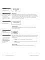
Information buttons contain serial numbers and firmware version information. The
properties of these buttons cannot be changed. Figure 11 shows the serial number
information button in the Setup page.
displayed in black and yellow
to indicate that they are only
for information and can’t be
changed.
Figure 11
Information button example
Adjustment buttons
You can use the UP and DN buttons to set adjustment buttons. The adjustment
button example in Figure 12 sets the baud rate for the RS-232 connector on the touch
panel.
Figure 12
Adjustment button example
Keypad buttons
The keypad button opens a keypad (Figure 13) so you can enter a password or value
assignment. All keypad buttons are interactive except for the entry display.
ViewPoint Wireless Touch Panels
Touch Panel Basics
15
Figure 13
Entry display
Keypad example
Keypad entry (0 - 9)
ENTER – Processes the entry
CLEAR – Resets the entry to 0
Decision buttons
Decision buttons (Figure 14) appear when an operation has two options and requires
you to verify the action before it is performed.
Figure 14
Decision button example
Decision buttons appear when you exit the Editor bar, send or receive a drawing,
designate a communication protocol, or make an operation error.
Status buttons
Status buttons (Figure 15) appear when you try to perform operations that do not
function correctly.
Figure 15
Status button example
Operation bars
Operation bars (Figure 16) appear in the place of the Editor bar when you have
selected a button or page edit operation. The operation bar indicates which edit
function is currently active. When an edit operation is selected, it remains active until
you press EXIT on the operation bar.
Figure 16
Operation bar example
16
Touch Panel Basics
ViewPoint Wireless Touch Panels
Touch to Continue buttons
Touch to Continue buttons (Figure 17) appear when an operation requires user
acknowledgement. An example of an operation that requires user acknowledgement
is resetting the factory defaults.
Figure 17
Touch to Continue button
example
ViewPoint Wireless Touch Panels
Touch Panel Basics
17
18
Touch Panel Basics
ViewPoint Wireless Touch Panels
Designing Touch Panel Pages
Note
Overview
Information within this section
These step-by-step instructions describe creating touch panel pages, buttons,
joysticks, bargraphs, and setting page color attributes. For in-depth information on all
the operations available on the touch panel, read through the Touch Panel Program
Reference section to learn about all the operations and techniques you can use to
design touch panel pages.
applies to all ViewPoint
models except as noted.
The VPT-CP and VPT-GS ViewPoint one-way models do not support bargraphs,
joysticks, VGA, or Video. These functions are available on the EDIT dropdown
menus and can be setup. However, the functions are not operational.
The VPW-CP and VPW-GS are two-way RF and supports bargraphs and joysticks.
Activating the Edit button
Note
If you have a pre-programmed
panel, you may not see the
Main page.
Before designing a touch panel page, activate the EDIT button that contains options
to add and configure touch panels and buttons. When powering up the mini-touch
panel, the first page is the Main page shown in Figure 18. Refer to Edit button and Go
to information in Touch Panel Program Reference if the Main page does not appear.
Figure 18
Main page
ViewPoint Wireless Touch Panels
Designing Touch Panel Pages
19
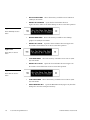
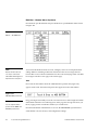
1. Press SETUP in the Main page to open the Setup page shown in Figure 19.
Figure 19
Setup page
Note
Viewpoint touch panel
information buttons are
displayed with a black fill.
Firmware
version
These buttons can’t be altered
and are only used to display
information. Examples of
these are the AXlink,
WIRELESS STATUS,
OUTPUT RESOLUTION,
vX.XX, and SERIAL #
buttons.
2. Press PROTECTED SETUP to open the password keypad shown in Figure 20.
Figure 20
Setup page and password
keypad
20
Designing Touch Panel Pages
ViewPoint Wireless Touch Panels
Note
If you press ENTER after
typing in an incorrect
password, you are
3. Enter 1988 in the keypad and press ENTER to open Protected Setup page
(Figure 21). For information on changing the password, refer to Touch Panel
Program Reference section. If you enter a wrong number, press CLEAR and reenter the number.
immediately returned to the
current page.
Figure 21
Protected Setup page with the
active EDITOR button
4. Press EDITOR to enable the Edit mode. The EDITOR button is highlighted when
enabled (Figure 21).
5. Press EXIT to close the Protected Setup page and return to the Setup page in Edit
mode.
6. Press EXIT again to return to the Main page. The EDIT button appears at the top
of the Main page indicating that Edit mode is active (Figure 22).
ViewPoint Wireless Touch Panels
Designing Touch Panel Pages
21
Figure 22
Main page with EDIT button
7. Press EDIT to open the Edit bar. BUTTON and PAGE in the Edit bar (Figure 23)
are used to design and modify button and page settings.
Figure 23
Edit bar
Main page and Edit bar
22
Designing Touch Panel Pages
ViewPoint Wireless Touch Panels
Creating a Page
Use the PAGE menu in the Edit bar to create touch panel pages.
Adding a page
1. Press PAGE on the Edit bar to open the PAGE menu shown in Figure 24.
Figure 24
PAGE menu
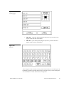
2. ADD to open the keyboard.
3. Enter NEW PAGE (Figure 25) using the keyboard. Page names can be up to 20
characters.
ViewPoint Wireless Touch Panels
Designing Touch Panel Pages
23
Figure 25
Keyboard
Note
Page naming does not allow
you to change the font type,
as is only available for
buttons.
4. Press EXIT CHANGE to add NEW PAGE to touch panel memory, close the
keyboard, and return to the new page.
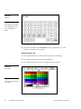
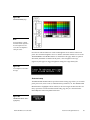
Setting the page color
1. Press the EDIT button to open the Edit bar on the newly created page.
2. Press PAGE on the Edit bar to open the PAGE menu.
3. Press PAGE COLOR to open the color palette shown in Figure 26.
Figure 26
Color palette
Note
The VPT-GS will display gray
scale options.
24
Designing Touch Panel Pages
ViewPoint Wireless Touch Panels
4. Select a page color from the palette. The page automatically changes to the new
color.
Creating a Button
Use the BUTTON menu in the Edit bar to create touch panel buttons.
Adding a button
1. Press EDIT to open the Edit bar.
2. Press BUTTON on the Edit bar to open the BUTTON menu shown in Figure 27.
Figure 27
BUTTON menu
3. Press ADD to open the ADD BUTTON operation bar (Figure 28).
Figure 28
ADD BUTTON operation bar
4. Touch and drag your finger horizontally down the LCD screen to create the
button as shown in Figure 29. The first touch point is the upper-left corner of the
button.
ViewPoint Wireless Touch Panels
Designing Touch Panel Pages
25
Figure 29
Width
Add a button example
Touch Point
Height
5. Release your finger from the panel to store the button dimensions into panel
memory.
6. Press EXIT to close the Edit bar.
Resizing a button
1. Press EDIT to open the Edit bar.
2. Press BUTTON on the Edit bar to open the BUTTON menu.
3. Press RESIZE to open the RESIZE BUTTON operation bar (Figure 30).
Figure 30
RESIZE BUTTON operation
bar
4. Push the edge of the button, and drag your finger horizontally across the screen
and down to resize the button (Figure 31).
Figure 31
Resizing a button
Touch any edge or
corner and drag to
resize.
5. Release your finger from the panel to store the button dimensions into the panel
memory.
6. Press EXIT in the Edit bar to exit Resize mode.
26
Designing Touch Panel Pages
ViewPoint Wireless Touch Panels
Button Properties
Note
One-way ViewPoints do not
support bargraphs, sliders,
joysticks, VGA, or video.
Note
The same steps apply to
setting properties for external
buttons.
Use the PROPERTIES option of the BUTTON menu in the Edit bar to set button
borders, page flips, button colors for channel on and off conditions, and channel and
variable text codes.
Setting the button properties
1. Press EDIT to open the Edit.
2. Press BUTTON on the Edit bar to open the BUTTON menu options.
3. Press PROPERTIES to open the PROPERTIES operation bar shown in
Figure 32.
Figure 32
PROPERTIES message bar
4. Press the button you just added to open the Button Properties page shown in
Figure 33. This page lists the properties for the active button.
Figure 33
Button Properties page
Note
The contents of the Button
Properties page will change
according to the type of button
selected. The example shown
here is for a GENERAL type
button.
ViewPoint Wireless Touch Panels
Designing Touch Panel Pages
27
Setting the button type
1. Press BUTTON TYPE in the Button Properties page. This opens the BUTTON
TYPE menu, shown in Figure 34. Press MORE at the bottom of the first page of
Button Types options to view the next page of options. Press PREV to view the
first page.
Figure 34
Button Types menu
2. Select a button type for the selected button to open the associated Button
Properties page for the selected button type. Each button type has its own Button
Properties page with settings specific to the button type. For example, select
GENERAL from the menu to set the selected button as a general button. This
opens the GENERAL Button Properties page, shown in Figure 33.
Setting the button border
1. Press BORDER in the Button Properties page to open the BUTTON BORDER
pages shown in Figure 35. These menu pages appear individually and can all be
viewed by using the MORE and PREV buttons.
28
Designing Touch Panel Pages
ViewPoint Wireless Touch Panels
Figure 35
BUTTON BORDER menu
pages
2. Press 3D RECTANGLE 1 to set the button border to 3D RECTANGLE 1 style and
return to the Button Properties page. The BORDER button in the Button
Properties page changes to show the active border type. In this case, the button
changes to the 3D-rectangle border.
Note
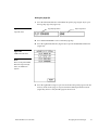
Setting the channel code
If DEVICE USED is set to 4
The channel buttons that set the device and button channel codes for the touch panels
are shown in Figure 36. Refer to Figure 143 for more information on DEV and CHAN.
and Base Device Number is
128, the Central Controller
recognizes bus devices 128,
129, 130, and 131.
Figure 36
CHANNEL code buttons
Note
The panel will not allow you to
enter a device number greater
than the DEVICE USED
without first displaying a
decision box. This box asks
you to decide whether you
accept the new selection or
default to the previous value.
ViewPoint Wireless Touch Panels
1. Press DEV to open the keypad and set the touch panel’s device number.
2. Enter 1, 2, 3, or 4 in the keypad. The AXCESS software program uses device
codes 1 through 4 to identify the touch panel. Refer to the Touch Panel Program
Reference section for detailed information.
a.
For 1-way ViewPoints, use device number 1 for AMX IR and RF. Use device
numbers 2, 3, and 4 for other manufacturer’s IR codes.
Designing Touch Panel Pages
29
b.
Note
If DEVICE USED is set to 4
and Base Device Number is
128, the Central Controller
recognizes bus devices 128,
129, 130, and 131.
For 2-way ViewPoints, AMX IR is not supported (38 KHz and 455 KHz) but
other manufacturer’s IR codes are supported by assigning ViewPoint device
numbers 2, 3, and 4 for IR codes.
3. Press ENTER to store the device number into memory, close the keypad, and
return to the Button Properties page.
4. Press CHAN to open a keypad and enter a channel value of 1 through 255 in the
Note
The channel code for nonactive buttons is 0 and for
active buttons is 1 through
255.
keypad. The AXCESS software program uses the channel code number to
identify the button and its’ programmed operations.
5. Enter 1 through 255 in the keypad. The AXCESS software program uses the
channel code number to identify the button and its operations.
6. Press ENTER to store the channel number in memory, close the keypad, and
return to the Button Properties page.
Setting the variable text code
Note
One-way ViewPoint touch
panels do not support variable
The variable text buttons that set the device and button channel codes for the touch
panels are shown in Figure 37.
text.
Figure 37
VAR TEXT code button
Note
1. Press DEV to open a keypad and set the device number.
The panel will not allow you to
2. Enter 1, 2, 3, or 4 in the keypad. The AXCESS software program uses device
enter a device number greater
than the DEVICE USED
without first displaying a
decision box. This box asks
you to decide whether you
accept the new selection or
default to the previous value.
3. Press ENTER to store the device number in memory, close the keypad, and
return to the Button Properties page.
4. Press CHAN to open a keypad and set the channel number.
5. Enter a channel value of 1 through 255 in the keypad. The AXCESS software
Note
The channel codes for nonactive buttons is 0, and active
buttons is 1 through 255.
30
codes 1 through 4 to identify the touch panel. Refer to the Touch Panel Program
Reference section in this manual for detailed information.
program uses the channel code number to identify the button and its operations.
6. Press ENTER to store the channel number into memory, close the keypad, and
return to the Button Properties page.
Designing Touch Panel Pages
ViewPoint Wireless Touch Panels
Setting the page flip
1. Press the left PAGE FLIP box in the Button Properties page (Figure 38) to open
the Page Flip Type list (Figure 39).
Page Flip Type button
Figure 38
Flip to Page button
Page FLIP boxes
2. Press FLIP STANDARD to select a standard page flip.
3. Press the right PAGE FLIP box (Figure 38) to open the PAGE FLIP TYPE menu
(Figure 39).
Figure 39
PAGE FLIP TYPE menu
Note
When selecting FLIP PREVIOUS in the Page FLIP type
button, the PAGE menu
appears.
4. Press the right FLIP to Page to open a list of all the touch panel pages stored into
memory. If the desired page is not present in the PAGE flip destination menu
(Figure 40), check to verify that the page has been saved.
ViewPoint Wireless Touch Panels
Designing Touch Panel Pages
31
Figure 40
PAGE flip destination menu
5. Press MAIN PAGE to set the page flip to the Main page.
Setting the button colors for channel-off conditions
1. Press the target button to open the Button Properties page
2. Press BORDER in the CHANNEL OFF subsection of the Button Properties page
(Figure 41).
Figure 41
CHANNEL OFF/ON COLOR
settings box
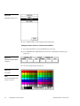
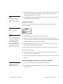
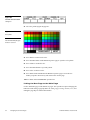
3. The color palette (Figure 42) appears.
Figure 42
Color palette
Note
The VPT-GS will display gray
shades for selection.
32
Designing Touch Panel Pages
ViewPoint Wireless Touch Panels
4. Press black to set the border color.
5. Press the FILL button in the Button Properties page to open the color palette.
6. Press white to set the fill color.
7. Press the TEXT button to open the palette
8. Press red to set the text color
9. Press EXIT SAVE CHANGE in the Button Properties page to store the new
button properties into memory and return to the current page
10. Press EXIT on the PROPERTIES operation bar
Adding text to a button
Use the BUTTON option in the Edit bar to add text to buttons, joysticks, and
bargraphs.
1. Press EDIT to open the Edit bar.
2. Press BUTTON on the Edit bar to open the BUTTON menu.
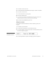
3. Press TEXT/IMAGE to add text into the button. The TEXT/IMAGE operation
bar shown in (Figure 43) appears.
Figure 43
TEXT/IMAGE operation bar
4. Press the target button to open the Text/Image page shown in Figure 44.
ViewPoint Wireless Touch Panels
Designing Touch Panel Pages
33
Figure 44
Text/Image page
Note
5. Press TEXT OFF to open the keyboard.
The CHANGE FONT button
6. Enter MAIN PAGE in the keyboard. The text appears in the message box at the
only appears when changing
the font of a function button
and does not apply to popup
pages.
top of the keyboard. If you exceed the space in the button, the touch panel edits
the message to fit in the space provided. Change the size of the button or reduce
the font size to compensate.
7. Press EXIT CHANGE to close the keyboard and return to the Text/Image page
Note
8. Press MAKE ON SAME AS OFF to set the text for both TEXT ON and TEXT OFF
You can’t create or edit buttons with Unicode fonts within
the on-board editor. Any use
of the TEXT/IMAGE button to
alter or create Unicode font
supported buttons must be
states of the button.
9. Press EXIT SAVE CHANGE to close the Text/Image page and return to the Main
page.
10. Press EXIT in the Edit bar to exit Edit TEXT/IMAGE mode.
done in TPDesign3 Touch
Panel Design Program.
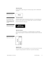
Adding an icon to a button
Use the BUTTON option in the Edit bar to add icons to buttons, joysticks, bargraphs,
and video windows. Refer to
34
Designing Touch Panel Pages
ViewPoint Wireless Touch Panels
Using TPDesign3 to Download Bitmaps, Icons, and Fonts for more information on
importing icons into your touch panel.
1. Press EDIT to open the Edit bar.
2. Press BUTTON on the Edit bar to open the BUTTON menu.
3. Press TEXT/IMAGE to add text to the button. The TEXT/IMAGE operation bar
appears.
4. Press the target button to open the Text/Image page.
5. Press ICON OFF to set the icon for the OFF state of the selected button. This
opens the ICONS menu (Figure 45), which contains a list of all the icons
currently available to the project
Figure 45
ICONS menu example
6. Select an icon from the menu. This sets the icon for the selected button’s Off state
7. On the Text/Image page, press MAKE ON SAME AS OFF to set the icon for both
On and Off states of the button.
8. Press EXIT SAVE CHANGE to set the button text and close the Text/Image page
and return to the NEW page.
9. Press EXIT in the Edit bar to exit Edit Text/Image mode and close the Edit bar.
Adding a bitmap to a button
Use the BUTTON option in the Edit bar to add bitmaps to buttons, joysticks,
bargraphs, and video windows. Refer to
ViewPoint Wireless Touch Panels
Designing Touch Panel Pages
35
Using TPDesign3 to Download Bitmaps, Icons, and Fonts for more information on
importing bitmaps into your touch panel.
1. Press EDIT to open the Edit bar.
2. Press BUTTON on the Edit bar to open the BUTTON menu (Figure 27).
3. Press TEXT/IMAGE to add text to the button. The TEXT/IMAGE operation bar
shown in Figure 43 appears.
4. Press the button to open the Text/Image page shown in Figure 44.
5. Press BTMP OFF to set the bitmap for the OFF state of the selected button. This
opens the BITMAPS menu. The BITMAPS menu contains a list of all the bitmaps
currently available to the project. An example BITMAPS menu is shown in
Figure 46.
Figure 46
BITMAPS menu example
6. Select a bitmap from the menu. This sets the bitmap for the selected button’s Off
state.
7. On the Text/Image page, press MAKE ON SAME AS OFF to set the bitmap for
both On and Off states of the button.
8. Press EXIT SAVE CHANGE to set the button text and close the Text/Image page
and return to the NEW page.
9. Press EXIT in the Edit bar to exit Edit Text/Image mode and close the Edit bar.
36
Designing Touch Panel Pages
ViewPoint Wireless Touch Panels
Using TPDesign3 to Download Bitmaps, Icons, and Fonts
TPDesign3 allows you to import bitmaps, icons and fonts into your touch panel from
an existing touch panel program. Use the Download to Panel command to download
a project file.
To download bitmaps, icons and/or fonts from an existing TPDesign3 project file:
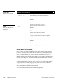
1. Launch the TPDesign3 software program and open a project file that contains the
desired bitmaps, icons, and fonts.
2. Select File from the menu bar to open the File menu.
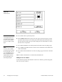
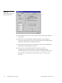
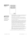
3. In the File menu, click on Download to Panel. This opens the Download to Panel-
Comm Settings tab shown in Figure 47. Use this tab to set the communications
port, baud rate, and other communication settings.
Figure 47
Download to Panel dialog
box: Comm Settings tab
Note
The Comm Settings tab is the
first tab in the Download To
Panel dialog that opens.
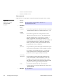
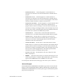
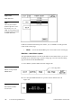
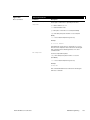
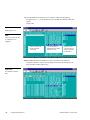
4. Use the Actions tab (Figure 48) to set the communication mode with the touch
panel and to select which elements of the project file you want to download to
the touch panel.
ViewPoint Wireless Touch Panels
Designing Touch Panel Pages
37
Figure 48
Sample Download To Panel
dialog box: Actions tab
5. I n the What To Send area, select one or more of the available options (Bitmaps,
Icons, Fonts).
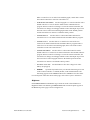
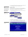
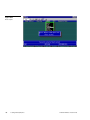
6. Select the mode of communication with the touch panel. After clicking on
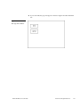
Connect, the AXlink window opens, as shown in Figure 49. The AXlink window
displays the AXlink ID and Available Panels fields.
7. The AXlink ID field displays the selected AXlink address. The Available Panels
field the device addresses that are available.
8. Once you have selected which elements to download, and set the
communications mode and AXlink device settings, click Begin to begin
downloading the project file into the touch panel. The bargraph at the bottom of
the Download To Panel dialog box indicates the progress (in percent) of the
download.
38
Designing Touch Panel Pages
ViewPoint Wireless Touch Panels
Figure 49
Sample Download To Panel
dialog box with AXlink window
Note
Although these pushbuttons
don't appear on-screen, their
functionality can be set just as
any other button on the touch
panel. Refer to the Button
Properties subsection for
further information on the
Properties’ page features.
9. After completing the download, cut, copy and paste buttons as needed. The
bitmaps, icons and fonts that were downloaded are now accessible via the
BITMAPS, ICONS and FONTS menus.
Button Properties for External Pushbuttons
If your touch panel comes with external pushbuttons, these can be configured with
features similar to on-screen buttons. Refer to Creating a Button, Button Properties, and
Properties Page – External Buttons for detailed information. Use the PROPERTIES
operation bar to assign properties to external pushbuttons. The BUTTON options and
VARIABLE TEXT features within the Properties page will not appear. Although the
Border and Color sections of this page appear, they are of no use to external
pushbuttons since they do not appear on-screen.
Creating an IR Macro Button
Creating an IR macro button allows controlling multiple devices with a single touch
panel button. You are only limited by touch panel IR memory (16 Kb). The following
steps provide an example of creating an IR macro button controlling a television,
VCR, and a satellite tuner. Syntax for a macro command is (refer to the AXCESS
Programming section):
The IR macro button will perform the following processes when pushed.
•
ViewPoint Wireless Touch Panels
Turn On a Television and set the audio volume.
Designing Touch Panel Pages
39
•
Turn On a VCR and select TV.
•
Turn On a satellite receiver.
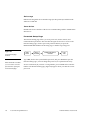
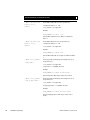
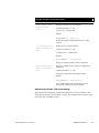
Pulse command
Figure 50 shows a sample pulse command format and description of the variables.
Figure 50
•
Format:
Sample Pulse command
format and variable
description
Sample
<time delay after pulse><CR>
•
Variables:
<device
number>:
<channel
number>:
<time
pulse on>:
<time delay
after pulse>:
<CR>:
•
40
$P <device number> <channel number> <time pulse on>
Designing Touch Panel Pages
Example:
This number represents an AXlink device that is associated
with 255 channels. The device number must be 2, 3, or 4.
This number represents one of 255 particular control
functions associated with a device. The channel number
must lie within the range of 1 and 255. For example, a
button programmed on a touch panel with device 3,
channel number 15 would be directly associated with the IR
code programmed at device 3, channel 15. When that
button is pressed, the touch panel transmits the IR code
programmed at device 3, channel 15.
This parameter represents the length of time that the pulse
will remain on. This number is a time in tenths of seconds.
For example, to keep the IR pulse on for 1 second, the
required parameter is 10. The largest number for this
parameter is 65535 or approximately 109 minutes.
This parameter represents the length of time between
pulses. This number is a time in tenths of seconds. For
example, to add a delay between pulses for 10 seconds,
the required parameter is 100. The largest number for this
parameter is 65535 or approximately 109 minutes.
This character indicates the end of the statement
(carriage return is pressing the RETURN key on the touch
panel keyboard).
$P 3 15 10 100<CR>
ViewPoint Wireless Touch Panels
This command will transmit the IR code at device 3, channel 15 for 1 second. Then,
the macro will pause 10 seconds before executing the next command or before
finishing the macro if no other commands exist.
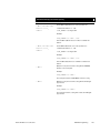
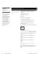
Wait command
The wait command is used as a delay between pulses. This command should be used
sparingly because the final parameter of the pulse command contains a delay
between instructions. Usually, this command will be necessary for the case where a
time delay is desired before starting any IR pulse sequences.
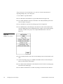
Figure 51 shows a sample pulse command format and description of the variables.
Figure 51
•
Format:
Sample Pulse command
format and variable
description
Sample
•
$W <time delay before pulse><CR>
Variables:
<time delay
before pulse>:
<CR>:
•
Example:
This parameter represents the length of time between
pulses. This number is a time in tenths of seconds. For
example, to add a delay between pulses for 100 seconds,
the required parameter is 1000. The largest number for
this parameter is 65535 or approximately 109 minutes.
This character indicates the end of the statement
(carriage return is pressing the RETURN key on the touch
panel keyboard).
$W 455<CR>
This command will wait 45.5 seconds before executing the next macro command.
Before you create an IR macro button, make sure that you have your equipment IR
files loaded into the ViewPoint. Refer to the section Loading Infrared (IR) Files. Load
the IR files in the order of satellite IR first, VCR IR second, and TV IR file last. This
loading order places the satellite file as ViewPoint device 4, the VCR as device 3, and
the TV as device 2.
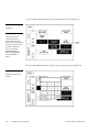
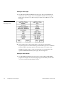
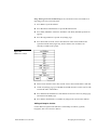
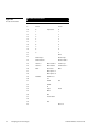
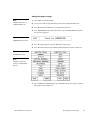
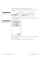
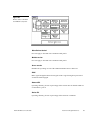
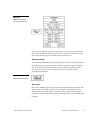
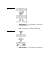
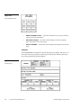
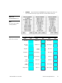
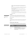
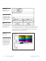
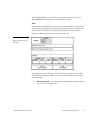
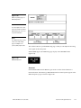
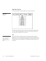
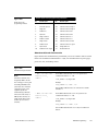
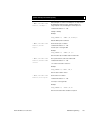
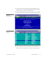
Figure 52 lists the IR code numbers for each device used in the following steps.
ViewPoint Wireless Touch Panels
Designing Touch Panel Pages
41
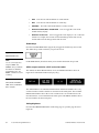
Figure 52
IR codes and functions
IR codes and functions
IR code #
Television
VCR
Satellite
1-8
9
Power
Power
10
0
11
1
1
12
2
2
13
3
3
14
4
4
15
5
5
16
6
6
17
7
7
18
8
8
19
9
9
Input select
21
0
Enter
22
Channel up ∧
Channel up ∧
23
Channel down ∨
Channel down ∨
24
Volume ∨
Main volume ∧
Volume up ∧
25
Volume ^
Main Volume
Volume down ∨
26
Mute
Rcvr mute
Mute
27
Main power on
28
Main power off
29
TV/Video
VCR1 tv/vcr
30
TV
31
VCR1
32
VCR2
33
ld
34
Tape
35
DCC
36
CD
37
Tuner am/fm
Sat
Audio
38
39
45
42
Designing Touch Panel Pages
Aux
Chan sel
ViewPoint Wireless Touch Panels
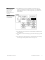
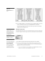
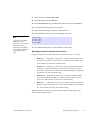
1. Create a button and label it Video Start.
2. Select EDIT, BUTTON, PROPERTIES.
3. In the PROPERTIES dialog, select BUTTON TYPE, and then select GENERAL.
4. In the BUTTON OPTIONS field, select NONE.
5. I n the CHANNEL dialog, set DEV to 1 and CHAN to 0.
6. In the STRING field enter the following using the keyboard:
Note
You must select the CHAR
NUMS button on the
$P 2 9 5 1 <CR>
$P 2 24 5 1 <CR>
$P 3 27 5 1 <CR>
$P 4 9 5 1 <CR>
Keyboard in order to enter the
adjacent text. There is a
space between the different
7. Press EXIT CHANGE, EXIT SAVE CHANGE, and then EXIT.
sets of numbers and between
the last number and the
<CR>.
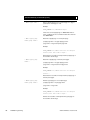
What happens when the example macro executes
Using the example in step 6, the following occurs when the macro is executed.
•
$P 2 9 5 1
•
$P 2 24 5 1
•
$P 3 27 5 1
•
$P 4 9 5 1
An IR push is sent to device 2 (TV) on channel 9 (Power on)
for a period of 5 tenths of a second and a one tenth of a second pause. The
<CR> indicates an end to the command string.
An IR push is sent to device 2 (TV) on channel 24 (increase
volume) for a period of 5 tenths of a second and a one tenth of a second
pause. The <CR> indicates an end to the command string. This command is
repeated for one more command string.
An IR push is sent to device 3 (VCR) on channel 27 (Main
power on) for period of 5 tenths of a second and a one tenth of a second
pause. The <CR> indicates an end to the command string.
An IR push is sent to device 4 (satellite receiver) on channel 9
(Power) for period of 5 tenths of a second and a one tenth of a second pause.
The <CR> indicates an end to the command string.
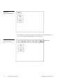
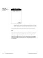
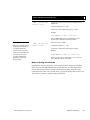
While the macro is executing, a touch to Continue button example (Figure 53) is
shown on the touch panel screen.
ViewPoint Wireless Touch Panels
Designing Touch Panel Pages
43
Figure 53
Touch to Continue button
example
If the screen is touched to cancel macro execution, all touch panel activity stops until
another button press occurs.
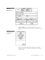
Creating a Joystick
Note
Joystick will function on
VPW-CP/VPW-GS only.
You can create a joystick with the BUTTON TYPE operation bar in the Button
Properties page. Joysticks (Figure 54) are vertical and horizontal direction controllers
you can use for camera operations such as pan and tilt.
Figure 54
Joystick
Before you start, make sure to connect the touch panel system to your Central
Controller. Otherwise, the joystick may not work properly. Refer to the Touch Panel
Program Reference section in this manual for more information.
Note
Adding a joystick to a page
Joystick will function on VPWCP/VPW-GS only.
Create a new button using the ADD operation bar in the BUTTON menu as described
in the Creating a Button subsection.
1. Press BUTTON on the Edit bar to open the Button menu.
2. Press PROPERTIES to open the PROPERTIES operation bar shown in
Figure 55.
Figure 55
PROPERTIES operation bar
3. Press the target button to open the Button Properties page for the selected button.
4. Press BUTTON TYPE to open the BUTTON TYPE menu.
44
Designing Touch Panel Pages
ViewPoint Wireless Touch Panels
5. Press JOYSTICK to set the target button as a joystick.
6. Press BUTTON OPTIONS on the Button Properties page to open the BUTTON
OPTION menu for Joysticks shown in Figure 56.
Figure 56
BUTTON OPTION menu for
Joysticks
7. Press CROSSHAIR CENTER to set a crosshair in the center of the joystick button
and return to the Button Properties page.
8. Press EXIT SAVE CHANGE to return to the Main page.
9. Press EXIT to exit from the PROPERTIES operation bar.
Setting the joystick properties
Note
1. Press EDIT, BUTTON, and the PROPERTIES operation bar.
Joystick will function on VPWCP/VPW-GS only.
2. Press the target button to open the Button Properties page.
3. Press BUTTON TYPE to open the BUTTON TYPE menu (Figure 34).
4. Press JOYSTICK in the BUTTON TYPE menu to open the Button Properties page
shown in Figure 57.
ViewPoint Wireless Touch Panels
Designing Touch Panel Pages
45
Figure 57
Button Properties page for
Joysticks
Note
If you followed the instructions
for Adding a joystick to a page
subsection, this button's
Properties page appears.
Note
If DEVICE USED is set to 4
and Base Device Number is
128, the Central Controller
recognizes bus devices 128,
129, 130, and 131.
Setting the channel code
The channel buttons that set the device and button channel codes for the touch panels
are shown in Figure 58.
Figure 58
CHANNEL code buttons
Note
1. Press DEV to open a keypad and set the joystick’s device number.
The panel will not allow you to
2. Enter 1, 2, 3, or 4 in the keypad. The device number specifies the device number
enter a device number greater
than the DEVICE USED
without first displaying a
decision box. This box asks
you to decide whether you
accept the new selection or
default to the previous value.
Note
The channel code for nonactive buttons is 0 and for
that the selected channel’s feedback displays.
3. Press ENTER to store the device number into memory, close the keypad, and
return to the Button Properties page.
4. Press CHAN to open the keypad and enter a channel value of 1 through 255 in
the keypad. The AXCESS software program uses the channel code number to
identify the button and its’ programmed operations.
5. Press ENTER to store the channel number in memory, close the keypad, and
return to the Button Properties page.
active buttons is 1 through
255.
46
Designing Touch Panel Pages
ViewPoint Wireless Touch Panels
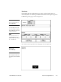
Setting the level code
The level buttons that set the device and number codes for the touch panels are
shown in Figure 59.
Figure 59
LEVEL code buttons
Note
1. Press DEV to open a keypad and set the device number.
The panel will not allow you to
2. Enter 1, 2, 3, or 4 in the keypad. The AXCESS software program uses device
enter a device number greater
than the DEVICE USED
without first displaying a
decision box. This box asks
you to decide whether you
accept the new selection or
default to the previous value.
codes 1 through 4 to identify the touch panel. Refer to the Touch Panel Program
Reference section for detailed information.
3. Press ENTER to store the level device number in memory, close the keypad, and
return to the Button Properties page.
4. Press NUM to open a keypad and set the level number assigned to the device.
5. Enter 1 in the keypad.
Note
Joysticks actually use two
6. Each device can have from 1 through 8 levels except for joysticks where the
range is from 1 through 7
level numbers. The first is for
the X-axis and the second is
Setting the joystick colors/shades for channel-off conditions
for the Y-axis. You only need
to specify the first level.
1. Press the target button to open the Button Properties page.
2. Press BORDER in the CHANNEL OFF COLOR section of the Button Properties
page (Figure 60).
Figure 60
CHANNEL OFF/ON COLOR
settings box
Note
Joystick will function on VPWCP/VPW-GS only.
ViewPoint Wireless Touch Panels
3. The color palette (Figure 42) appears.
Designing Touch Panel Pages
47
Figure 61
Color palette
Note
The VPT-GS will display gray
shades for selection.
4. Press black to set the border color.
5. Press the FILL button in the Button Properties page to open the color palette.
6. Press white to set the fill color.
7. Press the TEXT button to open the palette.
Note
8. Press red to set the text color.
Joysticks actually use two
9. Press EXIT SAVE CHANGE in the Button Properties page to store the new
level numbers. The first is for
the X-axis and the second is
for the Y-axis. You only need
to specify the first level.
button properties into memory and return to the current page
10. Press EXIT on the PROPERTIES operation bar
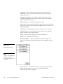
Creating a Bargraph
Note
Bargraphs will function on
VPW-CP/VPW-GS only.
Bargraphs (Figure 62) are level monitors and adjustable level controls. These levels
can be configured to monitor audio outputs, lighting levels, and adjust audio or light
levels. Before you start, make sure to connect the touch panel to your Central
Controller; otherwise, the bargraph may not work properly. Refer to the Touch Panel
Program Reference.
Figure 62
Bargraph
48
Designing Touch Panel Pages
ViewPoint Wireless Touch Panels
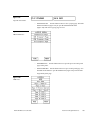
Adding a bargraph to a page
Note
1. Press EDIT to open the Edit bar.
Bargraphs will function on
VPW-CP/VPW-GS only
2. Create a new button using the ADD operation bar in the BUTTON menu.
3. Press BUTTON in the Edit bar to open the BUTTON menu.
4. Press PROPERTIES in the BUTTON menu to open the PROPERTIES operation
bar shown in Figure 63.
Figure 63
PROPERTIES operation bar
5. Press the target button to open the Button Properties page.
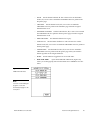
6. Press BUTTON TYPE to open the BUTTON TYPE menus shown in Figure 64.
Figure 64
BUTTON TYPE menus
Note
Bargraphs joysticks will
function on VPW-CP/VPWGS only.
7. Select VERTICAL BARGRAPH to open the Button Properties page for Vertical
Bargraphs shown in Figure 65.
ViewPoint Wireless Touch Panels
Designing Touch Panel Pages
49
Figure 65
Button Properties page for
Vertical Bargraphs
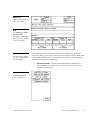
Setting the bargraph properties
Use the Button Properties page for Vertical Bargraphs shown in Figure 65 to set
channel, level, and button colors.
Note
Setting the channel code
Bargraphs will function on
VPW-CP/VPW-GS only.
The channel buttons that set the device and button channel codes for the touch panels
are shown in Figure 66.
Figure 66
Bargraph CHANNEL code
buttons
Note
The panel will not allow you to
enter a device number greater
than the DEVICE USED
without first displaying a
decision box. This box asks
1. Press DEV to open the keypad and set the device number.
2. Enter 1, 2, 3, or 4 in the keypad. The AXCESS software program uses device
codes 1 through 4 to identify the touch panel. Refer to the Touch Panel Program
Reference section for detailed information.
you to decide whether you
accept the new selection or
default to the previous value
50
3. Press ENTER to store the device number into memory, close the keypad, and
return to the Button Properties page.
Designing Touch Panel Pages
ViewPoint Wireless Touch Panels
4. Press CHAN to open a keypad and enter a channel value of 1 through 255 in the
keypad. The AXCESS software program uses the channel code number to
identify the button and its’ operations
Note
The channel code for non-
5. Press ENTER to store the channel number into memory, close the keypad, and
return to the Button Properties page.
active buttons is 0 and for
active buttons is 1 through
255.
Setting the level code
The level buttons that set the device and number codes for the touch panels are
shown in Figure 67.
Figure 67
LEVEL code buttons
Note
1. Press DEV to open a keypad and set the device number.
The panel will not allow you to
2. Enter 1, 2, 3, or 4 in the keypad. The AXCESS software program uses device
enter a device number greater
than the DEVICE USED
without first displaying a
decision box. This box asks
you to decide whether you
accept the new selection or
default to the previous value.
codes 1 through 4 to identify the touch panel. Refer to the Touch Panel Program
Reference in this manual for detailed information.
3. Press ENTER to store the level device number into memory, close the keypad,
and return to the Button Properties page.
4. Press NUM to open a keypad and set the level number assigned to the device.
5. Enter 1 in the keypad.
6. Press ENTER to store the level number into memory, close the keypad, and
return to the Button Properties page.
7. Press EXIT SAVE CHANGE, then EXIT to return to the New page with the EDIT
button.
Setting the bargraph colors/shades for channel-off conditions
Note
1. Press the target button to open the Button Properties page.
Bargraphs will function on
VPW-CP/VPW-GS only.
2. Press BORDER in the CHANNEL OFF COLOR section of the Button Properties
ViewPoint Wireless Touch Panels
page (Figure 60).
Designing Touch Panel Pages
51
Figure 68
CHANNEL OFF/ON COLOR
settings box
3. The color palette (Figure 42) appears.
Figure 69
Color palette
Note
The VPT-GS will display gray
shades for selection.
4. Press black to set the border color.
5. Press the FILL button in the Button Properties page to open the color palette.
6. Press white to set the fill color.
7. Press the TEXT button to open the palette.
8. Press red to set the text color.
9. Press EXIT SAVE CHANGE in the Button Properties page to store the new
button properties into memory and return to the current page.
10. Press EXIT on the PROPERTIES operation bar.
Linking the New Page to the Main Page
Use the Attributes page to link buttons to pages. This operation requires changing the
button text and setting a page flip. Refer to Adding a page, Creating a Button, Go to, and
Setting the page flip for detailed information.
52
Designing Touch Panel Pages
ViewPoint Wireless Touch Panels
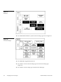
1. Open the Edit bar, press the active page button shown in Figure 70. Refer to the
Go to subsection for information on the use of the active page button
Active page button
Figure 70
Edit bar with active page
button
2. Press MAIN PAGE from the PAGE GOTO menu.
3. Press EDIT to open the Edit bar.
4. Press BUTTON on the Edit bar to open the BUTTON menu.
5. Press TEXT/IMAGE to change the Main page button text. The TEXT/IMAGE
operation bar (Figure 71) appears.
Figure 71
TEXT/IMAGE operation bar
6. Press the MAIN button to open the Text/Image page.
7. Press TEXT OFF to open the keyboard and delete MAIN.
8. Enter NEW PAGE. The text appears in the keyboard window.
9. Press EXIT CHANGE to close the keyboard and return to the Text/Image page.
10. Press MAKE ON SAME AS OFF to set the text for the button’s TEXT ON and
TEXT OFF states.
11. Press EXIT SAVE CHANGE to close the Text/Image page and return to the Main
page.
12. Press EXIT to exit the TEXT/IMAGE mode.
13. Press EDIT to open the Edit bar.
14. Press BUTTON to open the BUTTON OPTIONS menu.
15. Press PROPERTIES in the BUTTON OPTIONS menu to open the PROPERTIES
operation bar shown in Figure 72.
Figure 72
PROPERTIES operation bar
ViewPoint Wireless Touch Panels
Designing Touch Panel Pages
53
16. Press the NEW PAGE button to open the Button Properties page.
17. Press the page FLIP buttons (Figure 73) to set the page flip properties for the
button.
Figure 73
Page Flip Type button
Flip to Page button
Page FLIP buttons
18. Press the left Flip Type box in the Button Properties page to open the PAGE FLIP
TYPE menu (Figure 74).
Figure 74
PAGE FLIP TYPE menu
19. Press FLIP STANDARD to select a standard page flip and return to the Button
Properties page.
20. Press the right Page Flip box to set the destination page (Figure 75).
54
Designing Touch Panel Pages
ViewPoint Wireless Touch Panels
Figure 75
PAGE menu
21. Press NEW PAGE to set the page flip and return to the Button Properties page.
22. Press EXIT SAVE CHANGE to save changes, close the Button Properties page,
and return to the Main page.
23. Press EXIT on the PROPERTIES operation bar to close the Edit bar.
Exiting Edit Mode
This subsection describes exiting the EDIT mode once you finish designing touch
panel pages.
1. Press EXIT to close the Edit bar (Figure 76).
Figure 76
Edit bar
2. Press SETUP to open the Setup page shown in Figure 77.
ViewPoint Wireless Touch Panels
Designing Touch Panel Pages
55
Figure 77
Setup page
3. Press PROTECTED SETUP to open the Protected Setup page shown in Figure 78.
Figure 78
Protected Setup page
4. Press EDITOR to toggle EDIT mode Off.
5. Press EXIT to close the Protected Setup page and return to the Setup page
(Figure 77).
6. Press EXIT to close the Setup page and return to the Main page.
56
Designing Touch Panel Pages
ViewPoint Wireless Touch Panels
Another method of exiting the EDIT mode is to use the QUIT EDITOR button on the
Edit bar. Refer to the Edit Bar – Quit Editor option subsection for detailed information
on exiting the EDIT mode using this method.
1. Press EXIT to open the Edit bar shown in Figure 76.
2. Press the QUIT EDITOR button to open the Quit the On-Board Editor decision
button.
3. If you select YES, the current page will appear without the Edit bar.
ViewPoint Wireless Touch Panels
Designing Touch Panel Pages
57
58
Designing Touch Panel Pages
ViewPoint Wireless Touch Panels
Touch Panel Program Reference
Overview
This section contains operation flowcharts, instructions, and menu option
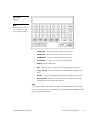
descriptions. The buttons shown in Figure 79 appear when you power up the touch
panel.
Figure 79
Main page
Note
The information within this
section applies to all
ViewPoint models.
Setup Page
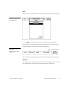
Press the SETUP button from the Main page, to open the Setup page shown in
Figure 80. Use the Setup and Protected Setup pages to configure how the touch panel
operates.
ViewPoint Wireless Touch Panels
Touch Panel Program Reference
59
Figure 80
Optional
WIRELESS
STATUS button
for WAV-PK and
SMT-PK wireless
control
Setup page
Note
The WIRELESS STATUS
button appears when a WAVPK or SMT-PK is attached to
the touch panel.
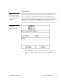
Beep
The Beep button sets the duration of the audible beep provided by the touch panel.
The values are 0 to 5. Using 0 turns the beep tone off and 1 through 5 provide the
audible beep and gradually increase the beep duration.
Figure 81
BEEP button
Note
You can set the beep value
using the 'ABEEP' and
'ADBEEP' Send_ Commands
described in the AXCESS
Programming section. The
'QBEEP' command is used for
overriding.
60
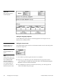
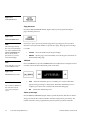
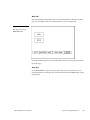
Display timer
The DISPLAY TIMER button (Figure 82) sets the length of time the touch panel can
be idle before activating screen-saver sleep mode.
Touch Panel Program Reference
ViewPoint Wireless Touch Panels
Figure 82
DISPLAY TIMER button
When the touch panel goes into screen-saver mode, the LCD is powered-down. With
a setting of 5, the panel goes into screen-saver mode if there is no activity for 5
minutes. Press the UP and DN buttons to set the DISPLAY TIMER. The minimum
time is 1 minute and the maximum is 240 minutes.
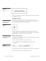
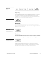
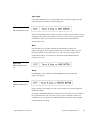
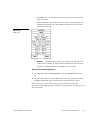
Set time and date
Press SET TIME AND DATE to open the page shown in Figure 83.
Figure 83
Set Time And Date page
Use this page to set the year, hour, month, minute, day, second, day/month, and
clock display.
ViewPoint Wireless Touch Panels
•
YEAR
•
HOUR
•
MONTH
Press the UP and DN buttons to set the year.
Press the UP and DN buttons to set the hour.
Press the UP and DN buttons to set the month.
Touch Panel Program Reference
61
•
MIN
Press the UP and DN buttons to set the minute.
•
DAY
Press the UP and DN buttons to set the day.
•
SECOND
•
DISPLAY MONTH/DAY, DAY/MONTH
Press the UP and DN buttons to set the seconds.
Press to toggle the order of the
month and day display.
•
Press to toggle the clock display to a 12- or 24-hour
format. For example, the 12-hour clock format changes from 12:00 to 1:00,
and the 24-hour clock changes from 12:00 to 13:00.
DISPLAY 12:00/24:00
Double beep
Press the DOUBLE BEEP button (Figure 84) to toggle the double beep ON or OFF.
The double beep sounds each time you press the screen.
Figure 84
DOUBLE BEEP button
Note
You can set the beep value
Set the BEEP button (described earlier) to 0 to disable the double-beep sound.
using the 'ABEEP' and
'ADBEEP' Send_ Commands
AXlink, output resolution, vX.XX, and serial number
described in the AXCESS
The AXlink, OUTPUT RESOLUTION, vX.XX, and SERIAL # buttons shown in
Figure 85 are information buttons (display only).
Programming section. The
'QBEEP' command is used for
overriding.
Figure 85
AXlink, OUTPUT RESOLUTION, vX.XX, and SERIAL #
button examples
The AXlink button is an AXCESS communication indicator that blinks once every
second when the Central Controller is connected to the touch panel. The OUTPUT
RESOLUTION button shows the screen resolution. The vX. XX button shows the
current firmware version installed in the touch panel. The SERIAL # button shows
the serial number for the touch panel.
Setting brightness
Press the SET BRIGHTNESS button in the Setup page to open the page shown in
Figure 86.
62
Touch Panel Program Reference
ViewPoint Wireless Touch Panels
Figure 86
SET BRIGHTNESS page
Note
A lower brightness settings
information button appears in
the lower right-hand of the
screen when the brightness
setting exceeds 5
Press the UP and DN buttons to set the LCD brightness and contrast on the touch
panel. The maximum brightness level is 5 and the maximum contrast level is 12. The
TRANSPARENT and ABORT buttons are disabled for this page. When an optional
WavePack/SmartPack is attached to the panel, a lower brightness message
(Figure 87) will appear to suggest brightness settings for longer battery life.
Figure 87
Lower brightness information
message
Protected setup
The PROTECTED SETUP button opens the Protected Setup page where you set touch
panel passwords, mouse control, communications parameters, etc. The PROTECTED
SETUP button is highlighted when enabled, as shown in Figure 88. Because there are
many operations associated with Protected Setup page, they are described in the
Error! Reference source not found. subsection.
Figure 88
PROTECTED SETUP button
(highlighted)
ViewPoint Wireless Touch Panels
Touch Panel Program Reference
63
Show palette
Press SHOW PALETTE to open the color palette. Pressing the screen again will cause
you to leave the Show Palette page.
Wireless status (optional WAV-PK)
Note
The WAV-PK page provides
read-only information about
the Wave-Pack. The only
setting that can be changed is
the SLEEP TIMEOUT value.
The WIRELESS STATUS button appears on the Setup page when an AXR-WAVES
Wireless AXlink Virtual Emulator Server is connected to the touch panel. The WAVPKM provides wireless two-way RF spread-spectrum touch panel control and
contains a lead-acid rechargeable battery that supplies independent power to the
panel. Refer to the WAVE 2-Way Wireless Accessories and Adapters for Touch Panels
instruction manual for detailed setup information. Press the WIRELESS STATUS
button to open the WAV-PK page shown in Figure 89.
Figure 89
WAV-PK page
The Wave-Pack page shows the following information:
•
64
Touch Panel Program Reference
Press the UP and DN buttons to set the sleep time-out.
The minimum time-out is 1 minute and maximum is 120 minutes. When the
touch panel goes to sleep, all communication and battery discharge stops. If
the time-out is set to 5, the panel goes into sleep mode if there is no activity
for 5 minutes. The touch panel automatically wakes up when you touch the
screen for more than 0.5 seconds.
SLEEP TIMEOUT
ViewPoint Wireless Touch Panels
Note
•
Wave-Pak Not Locked/Locked
•
Battery Voltage XX.X
•
RSSI XXX%
Shows the strength of the AXR-WAVES signal received by
the touch panel. The signal strength fluctuates between 0% and 100% as
shown by a horizontal gauge moving from left to right.
•
GROUP ID
Shows the GROUP ID number on the touch panel used to
communicate with the wireless AXR-WAVES with the same group ID
number. The group ID range is 0 – 15. The group ID setting overrides the
DIP switch setting on the WAV-PK.
•
Module Version vX.XX
The GROUP ID number can
be set from the Wireless Settings page in the Protected
Setup page. Refer to the
Wireless settings subsections
Shows the firmware version installed in the
•
Fully Charged/Not Charging/Charging
•
Network Eff. XXX%
Shows the communication efficiency of bidirectional
RF transmissions between the touch panel and AXR-WAVES. The efficiency
percentage (0–100%) is determined by the number of retries required to
complete a panel operation.
•
Shows the device range that your server can recognize.
Devices outside that range will not be recognized.
•
Server Devices XXX
Shows the group address for the AXR-WAVES
communicating with the touch panel.
•
Server Version
The Network Eff. XXX% and
Device Eff. XXX% information
buttons are the best indicators
of communication.
Shows the voltage level of the lead-acid
rechargeable battery in the WAV-PK.
WAV-PK.
for detailed information.
Note
Appears when an optional WAV-PKM
is connected to the touch panel. Not locked indicates the touch panel is not
communicating with the AXR-WAVES. Locked indicates the touch panel is
locked on (communicating) to the AXR-WAVES connected to the Central
Controller.
Fully Charged appears when
the battery in the WAV-PK is fully charged. Not Charging appears when the
lead-acid battery is not charging. Charging appears when the lead-acid
battery is charging. The shaded area is a horizontal gauge moving from left
to right as the battery voltage level increases.
Device Range
Shows the firmware version installed in the AXR-
WAVES.
ViewPoint Wireless Touch Panels
•
Supply Voltage vX.XX
Shows the voltage level of the external power
supply (optional) connected to the WAV-PK.
•
Shows the strength of the AXR-WAVES signal
received by the touch panel. The shaded area in the horizontal gauge moves
Device Eff. XXX%
Touch Panel Program Reference
65
from left to right as the RF signal intensity increases. The shaded area
fluctuates between 0% and 100%.
Note
Wireless status (optional SMT-PK)
This SMT-PK page provides
read-only information about
the Smart Pack. The only
setting that can be changed is
The WIRELESS STATUS button appears on the Setup page when a SmartPack is
connected to the touch panel. Press the WIRELESS STATUS button to open the
optional page shown in Figure 91.
the SLEEP TIMEOUT value.
Figure 90
SMT-PKM page
Refer to the SmartPacks for TiltScreen Touch Panels instruction manual for detailed
information. The SmartPack page shows the following information:
66
•
Press the UP and DN buttons to set the time-out. The
minimum time-out is 1 minute and maximum is 120 minutes. When the
panel goes to sleep, all communication and battery discharge stops. If the
time-out is set to 5, the panel goes into sleep mode if there is no activity for 5
minutes. The panel wakes up when you touch the screen.
•
Appears when an optional SMT-PK is
connected to the panel. Not locked indicates the panel is not communicating
with the AXR-RF RF receiver. Locked indicates the panel is locked on to the
AXR-RF connected to the Central Controller.
•
Battery Voltage XX.X
Touch Panel Program Reference
SLEEP TIMEOUT
Smart-Pak Not Locked/Locked
Shows the voltage level of the lead-acid
rechargeable battery in the SMT-PK.
ViewPoint Wireless Touch Panels
Note
•
Shows the firmware version installed in the
SMT-PK.
Refer to the Wireless status
(optional WAV-PK) subsection
Module Version vX.XX
•
Fully Charged/Not Charging/Charging
•
AMX RF ON/OFF
•
Supply Voltage vX.XX
Shows the voltage level of the external power
supply (optional) connected to the SMT-PK.
•
AMX IR 38 kHz/455 kHz/OFF
for information on how to set
the RF and IR.
Fully Charged appears when
the battery in the SMT-PK is fully charged. Not Charging appears when the
lead-acid battery is not charging. Charging appears when the lead-acid
battery is charging. The shaded area is a horizontal gauge moving from left
to right as the battery voltage level increases.
Shows RF transmission on or off.
Shows the IR transmitting frequency to
38 kHz, 455 kHz, or OFF.
Wireless settings for VPT-CP and VPT-GS
The WIRELESS SETTINGS button appears on the Setup page. The VPT-CP and VPTGS provide one-way touch panel control, and transmits RF and high or lowfrequency IR signals. The ViewPoint contains a Nickel Metal Hydride rechargeable
battery that supplies independent power to the touch panel. Press the WIRELESS
SETTINGS button to open the page shown in Figure 91.
Figure 91
WIRELESS SETTINGS page
(VPT-CP and VPT-GS)
•
ViewPoint Wireless Touch Panels
SLEEP TIMEOUT
Press the UP and DN buttons to set the sleep time. The
minimum sleep time is 0 (off) and maximum is 120 minutes. When the touch
panel goes to sleep, all communication and battery discharge stops. If the
sleep time is set to 5, the panel goes into sleep mode if there is no activity for
Touch Panel Program Reference
67
5 minutes. The touch panel wakes up when you touch the screen for more
than .5 seconds.
•
ViewPoint Module
•
Module Version VX.XX
Not functional at this time.
Shows the ROM firmware version installed in
the ViewPoint.
•
Battery Voltage XX.X
•
Battery Not Charging/Battery Charging
Battery Not Charging
appears when the Nickel Metal Hydride battery is not charging. Battery
Charging appears when the Nickel Metal Hydride battery is charging. The
shaded area in the horizontal gauge button moves from left-to-right as the
battery voltage level increases.
•
Supply Voltage VX.XX
•
AMX RF ON / OFF
•
AMX IR 38 kHz/455 kHz/OFF
Shows the voltage level of the Nickel Metal
Hydride rechargeable battery.
Shows the voltage level of the external power
supply connected to the ViewPoint.
Toggles RF transmission on or off.
Toggles the IR transmitting frequency to
38 kHz, 455 kHz, or off.
Wireless Status for VPW-CP and VPW-GS
The WIRELESS STATUS button appears on the Setup page. The ViewPoint provides
two-way RF control and provides one-way IR signaling. The ViewPoint contains a
Nickel Metal Hydride rechargeable battery that supplies independent power to the
touch panel. Press the WIRELESS SETTINGS button to open the page shown in
Figure 92.
68
Touch Panel Program Reference
ViewPoint Wireless Touch Panels
Figure 92
Wireless status for VPW-CP
and VPW-CP touch panels.
Wave-Pak not locked
Does not apply to the VPW-CP or VPW-GS touch panels.
Module version
Does not apply to the VPW-CP or VPW-GS touch panels.
Server version
Identifies the operating version of the AXR-WAVES WaveServer firmware.
RSSI
Radio signal strength indicator showing the relative signal strength in percent and
visual horizontal bargraph.
Network Eff.
Operating efficiency (shown in percentage) of the current network that the VPW-CP
or VPW-GS is a part of.
Device Eff.
Operating efficiency (shown in percentage) of the VPW-CP or VPW-GS.
ViewPoint Wireless Touch Panels
Touch Panel Program Reference
69
Device range
Indicates the assignable device number range (for RF operation) available for the
VPW-CP or VPW-GS.
Server devices
Identifies the device numbers of the devices communicating with the AXR-WAVES
WaveServer.
Protected Setup Page
The Protected Setup page allows you to set passwords, mouse controls, and
communications parameters. The flowchart in Figure 93 shows how to access the
Protected Setup page, which is password-protected. When you press the
PROTECTED SETUP button on the Setup page, a number keypad appears.
Figure 93
Protected Setup page
flowchart
Note
When the Edit bar is enabled,
you do not have to enter the
password when opening the
Protected Setup page.
70
MAIN
PAGE
SETUP
BUTTON
PROTECTED SETUP
BUTTON
TYPE
1988
Type 1988, which is the system default password, and press ENTER to open the
Protected Setup page. (You can change the password, as explained in the Setup
Password subsection.) If you enter a wrong number, press CLEAR and re-enter the
number. The Protected Setup page (Figure 94) appears when you enter the correct
password.
Touch Panel Program Reference
ViewPoint Wireless Touch Panels
Figure 94
Protected Setup page
Baud
The BAUD button (Figure 95) sets the baud rate. The baud rate is automatically set to
38.4. The BAUD rate is for communicating with your PC when downloading a
program or new firmware.
Figure 95
BAUD button
Note
Make sure to match the baud
rate for communications with
TPDesign3.xx.
•
Press the UP and DN buttons to set the data communication speed
with the . Available baud rates are 300, 600, 1200, 2400, 4800, 9600, 19.2, and
38.4.
BAUD
Device base
Press the DEVICE BASE button (Figure 96) to open a keypad and set the base address
for the touch panel. The base address range is from 1 through 255.
ViewPoint Wireless Touch Panels
Touch Panel Program Reference
71
Figure 96
DEVICE BASE button
Device used
Note
If four devices are used, and
the base address is 128, then
the touch panel will
consecutively use device
numbers 128, 129, 130, and
131.
Press the DEVICE USED button (Figure 97) to open a keypad and set the panel’s
device number from 1 through 4. Each device number supports up to 255-channel
code button assignments. The multiple device settings allow you to create up to four
unique touch panel buttons and/or pages. This value is used to determine the
current device being used by the panel.
Figure 97
DEVICE USED button
Setup password
Press the SETUP PASSWORD button (Figure 98) to open a keypad and set the
numeric SETUP password.
Figure 98
SETUP PASSWORD button
Warning
If you change the password
number, record the new
number and keep it in a
secure place. If you change
the password, AMX cannot
provide you with the
The password number range is 1 through 5,999. (Do not use zero.) Do not change the
Setup page password unless you are concerned about unauthorized access to the
touch panel pages.
•
CLEAR
•
ENTER
password.
Press to clear the number in the keypad display.
Press to enter the new password into touch panel memory and
close the keypad.
Power up page
Press the POWER UP PAGE button to open the PAGE menu (Figure 99).
72
Touch Panel Program Reference
ViewPoint Wireless Touch Panels
Figure 99
POWER UP PAGE button
and example PAGE menu
Select a page to designate as the first page to appear when you power up the touch
panel. Select NONE to disable this option. If none is selected, the last selected page
will be the first active page the next time the touch panel is used.
Wake up message
Press WAKE UP MESSAGE (Figure 100) to open the touch panel keyboard, and enter
an ASCII string to be sent to the Central Controller when the touch panel wakes up.
You can program the Central Controller to perform specific operations when the
message is received. Refer to the AXCESS Programming section for detailed
programming information.
Figure 100
WAKE UP MESSAGE button
Auto assign
Press AUTO ASSIGN (Figure 101) to enable the automatic channel assignment. This
option sets the touch panel to prompt you to manually or automatically assign a
channel number (1 through 255) to a new button. Once selected, the touch panel
assigns the lowest unused channel number to the button. Press AUTO ASSIGN again
to disable.
ViewPoint Wireless Touch Panels
Touch Panel Program Reference
73
Figure 101
AUTO ASSIGN button
Page password
Press the PAGE PASSWORD button (Figure 102) to open a keypad and assign a
page’s numeric password.
Figure 102
PAGE PASSWORD button
Note
This numeric password applies to the touch panel pages
If you try to open a password-protected page, the keypad appears, and you must
enter the correct password number to open the new page. The page password range
is 1–5,999.
only, and is separate from the
SETUP PASSWORD button
that sets up the numeric
password for access to the
•
CLEAR
•
ENTER
Protected Setup page.
Clears the number in the keypad display.
Sets the page password number, closes the keypad, and returns to
the Protected Setup page.
Calibrate
Note
Press and hold for 2 seconds
to enter Calibration mode
Press CALIBRATE to open the CALIBRATE decision button shown in Figure 103 and
reset the vertical and horizontal touch points on the LCD.
Figure 103
CALIBRATE decision button
Note
•
YES
•
NO
The crosshair for calibration is
first shown at the top-left
corner of the touch panel
Starts the calibration process. Carefully press each crosshair that
appears using your finger or dull pointer. When the calibration process is
complete, press the screen to return to the Protected Setup page.
Cancels the calibration process.
screen.
Power up message
Press POWER UP MESSAGE (Figure 104) to open the keyboard, and enter an ASCII
string to be sent to the Central Controller when the touch panel is powered up. The
Central Controller can be programmed to perform specific operations when the
74
Touch Panel Program Reference
ViewPoint Wireless Touch Panels
message is received. Refer to the AXCESS Programming section for detailed
programming information.
Figure 104
POWER UP MESSAGE
button
System page
Press the SYSTEM PAGE button (Figure 105) to open the System page (Figure 106).
Figure 105
SYSTEM PAGE button
Figure 106
System page
Warning
The System page should only
be used to purge unwanted
buttons, bitmaps, icons, fonts,
and stored touch panel
settings. Before using this
page, make sure you have a
backup copy of the touch
panel program stored in the
TPDesign3 software program.
If you press YES on any of
the DELETE buttons, the
stored data is permanently
erased from panel memory.
•
Opens the decision button shown in
Figure 107. Press YES to clear all touch panel buttons or NO to cancel the
operation.
DELETE ALL BUTTONS
Figure 107
Delete All Buttons decision
button
ViewPoint Wireless Touch Panels
Touch Panel Program Reference
75
•
BUTTON MEM FREE
Shows the memory available to store buttons in
1,024-byte increments.
•
DELETE ALL BITMAPS
•
BITMAP MEM FREE
Shows the memory available to store bitmap
graphics in 1,024-byte increments.
•
Opens the decision button shown in Figure 109.
Press YES to clear all the icons or NO to cancel the operation.
•
ICON MEM FREE
Opens the decision button shown in
Figure 108. Press YES to clear all the bitmaps or NO to cancel the operation.
Figure 108
Delete All Bitmaps decision
button
DELETE ALL ICONS
Figure 109
Delete All Icons decision
button
Shows the memory available to store icons in 1,024-
byte increments.
•
DELETE ALL FONTS Opens the decision button shown in Figure 110.
Press YES to clear all the fonts or NO to cancel the operation.
•
FONT MEM FREE
Figure 110
Delete All Fonts decision
button
Shows the memory available to store fonts in 1,024-
byte increments.
•
76
Touch Panel Program Reference
Opens the BITMAPS menu (Figure 111) that lists
bitmap files stored in touch panel memory.
SHOW BITMAPS ID’S
ViewPoint Wireless Touch Panels
Figure 111
BITMAPS menu
•
Opens the ICONS menu (Figure 112) that lists icons
stored in touch panel memory.
SHOW ICONS ID’S
— MORE
— ABORT
Forwards the menu listing.
Cancels the menu process and returns to the current page.
Figure 112
ICONS menu
•
ViewPoint Wireless Touch Panels
Opens the FONTS menu (Figure 113) that lists fonts
stored in touch panel memory.
SHOW FONTS ID’S
Touch Panel Program Reference
77
Figure 113
FONTS menu
Note
You can use the TPDesign3
software program to import
variable fonts into the panel.
Warning
You should only use the
FACTORY RESET button to
erase all stored data in the
touch panel. The data cannot
be recovered after it is
•
erased.
Opens the decision button shown in Figure 114. Press
YES to clear all touch panel memory or NO to cancel the operation.
FACTORY RESET
Figure 114
CLEAR MEMORY decision
button
Editor
Press EDITOR (Figure 115) in the Protected Setup page to activate the EDIT mode.
Figure 115
EDITOR button
Note
You can exit from the onboard editor by pressing the
QUIT EDITOR button on the
Edit bar. Refer to the Edit Bar
– Quit Editor option
subsection for detailed
When you exit the Protected Setup page, the EDIT button appears on the top or
bottom of the LCD. Press the EDIT button to open the Edit bar (Figure 116) and create
buttons, pages, popup pages, and set a wide variety of touch panel settings. The
active touch panel page name also appears in the active Edit bar. For example, the
Edit bar sample in Figure 116 shows the current page name is New page. Because
there are so many operations associated with the EDIT button, they are described in
the Edit button subsection.
information.
78
Touch Panel Program Reference
ViewPoint Wireless Touch Panels
Figure 116
Edit bar
Page tracking
Press PAGE TRACKING (Figure 117) to toggle the page tracking ON or OFF. When
page tracking is enabled, the touch panel sends page data back to the Central
Controller or vice versa, depending on how you set the touch panel. Page tracking
data can be used to control pages in multiple touch panels.
Figure 117
PAGE TRACKING button
Sleep message
Press SLEEP MESSAGE (Figure 118) to open a keyboard and enter a message to
appear when the touch panel goes into sleep mode. Refer to Display Timer to set the
touch panel’s screen-saver mode.
Figure 118
SLEEP MESSAGE button
Function show
Press FUNCTION SHOW (Figure 119) to display channel code numbers and variable
text code numbers on touch panel buttons, joysticks, sliders, and bargraphs.
Figure 119
FUNCTION SHOW button
As shown in Figure 120, the upper-left corner of a button shows a base device
number followed by a channel code number. The bottom-right corner of a button
shows the variable text number followed by the variable text channel.
ViewPoint Wireless Touch Panels
Touch Panel Program Reference
79
Figure 120
Base
device
Channel code
number
Function show button and
slider example
2, 1
3, 132
Button
LIGHT
PANEL
Slider
2, 255
1,255
Variable text
device number
Level channel
Text channel
Level device
number
Wireless Settings for VPW-CP and VPW-GS
The WIRELESS STATUS button appears on the Setup page. The ViewPoint provides
two-way RF control and provides one-way IR signaling. The ViewPoint contains a
Nickel Metal Hydride rechargeable battery that supplies independent power to the
touch panel. Press the WIRELESS SETTINGS button to open the page shown in
Figure 121.
Figure 121
ViewPoint 2-way Wireless
Settings
Note
The GROUP ID can be
altered. Once changed, the
value is reflected in the
GROUP ID button located in
the WAV-PKM page. Refer to
the Wireless status (optional
WAV-PKM) subsection for
detailed information.
80
Touch Panel Program Reference
ViewPoint Wireless Touch Panels
Wave-Pak not locked
Does not apply to the VPW-CP or VPW-GS touch panels.
RSSI
Radio signal strength indicator showing the relative signal strength in percent and
visual horizontal bargraph.
Network Eff.
Operating efficiency (shown in percentage) of the current network which the VPWCP or VPW-GS is a part of.
Device Eff.
Operating efficiency (shown in percentage) of the VPW-CP or VPW-GS.
Device range
Indicates the assignable device number range (for RF operation) available for the
ViewPoint.
Server devices
Identifies the device numbers of the devices communicating with the AXR-WAVES
WaveServer.
Wireless settings (optional SMT-PKM)
Press the WIRELESS SETTINGS button that appears in the Protected Setup page to
opens the Wireless Settings page (Figure 122) for the Smart-Pack. The radio
frequency and infrared buttons can be modified on-screen and can work together.
Refer to the Wireless status subsection for detailed information of the buttons in
Figure 122.
ViewPoint Wireless Touch Panels
Touch Panel Program Reference
81
Figure 122
Wireless Settings page for
SMT-PKM
Note
The AMX RF and AMX IR can
function simultaneously. Refer
to the Wireless status
(optional SMT-PKM)
subsection for detailed
information.
Edit button
Press EDITOR in the Protected Setup page to enable EDIT mode. The Protected Setup
page remains open until you press EXIT. Then, the EDIT button appears on every
page. The flowchart in Figure 123 shows the sequence to activate EDIT mode.
Figure 123
EDIT mode activation
MAIN
PAGE
PROTECTED
SETUP
SETUP
TYPE
1988
EDITOR
BUTTON
flowchart
EXIT
BUTTON
Note
EXIT
BUTTON
You can use the QUIT
EDITOR button to exit the Edit
mode and avoid re-entering
the Protected Setup page.
82
Press EDITOR to activate Edit mode (Figure 124). Press EXIT twice to return to the
Main page.
Touch Panel Program Reference
ViewPoint Wireless Touch Panels
Figure 124
Enabled EDITOR button in
the Protected Setup page
Note
The position of the EDIT
button depends on whether
you have, at any time,
selected MOVE EDIT from the
PAGE menu. Refer to the
Move edit subsection for
detailed information.
When the Edit mode is enabled, the EDIT button (Figure 125) appears on the top or
bottom of each touch panel page.
Figure 125
Edit mode
ViewPoint Wireless Touch Panels
Touch Panel Program Reference
83
Edit Bar - Button Menu Options
Press EDIT to open the Edit bar and press BUTTON to open the Button menu shown
in Figure 126.
Figure 126
Edit bar — BUTTON menu
Note
Buttons with Unicode fonts
can only be created and
edited within TPDesign3, then
You can use the BUTTON menu to create, configure, and revise touch panel button
settings. Buttons containing usable fonts cannot have their text or images altered
because their code is locked. The Edit bar also shows the current page name. The Edit
bar in Figure 126 shows New page is the current page.
imported to the touch panel.
Add
Press ADD to add a button when the ADD BUTTON operation bar (Figure 127)
appears on the LCD. The first touch point is the upper-left corner of the button.
Figure 127
ADD BUTTON operation bar
Note
You can adjust the button
position with the MOVE and
RE-SIZE operation bars.
84
Drag your finger horizontally across the screen and down to set the height and width
of the button. When the new button appears on the page, the message bar shows you
the X/Y page-position coordinates and the X/Y resolution size.
Press the EXIT button in the Edit bar to exit. Use the PROPERTIES operation bar to
set the button color, border style, and configuration settings.
Touch Panel Program Reference
ViewPoint Wireless Touch Panels
Copy image
Press COPY IMAGE to copy an existing button onto a touch panel page when the
COPY BUTTON operation bar (Figure 128) appears.
Figure 128
COPY BUTTON operation bar
Touch the target button and drag the new button to another position. When you start
dragging the new button, the message bar shows you the current X/Y page-position
coordinates and the X/Y resolution size. Press EXIT on the COPY BUTTON
operation bar to exit.
Move
Press MOVE to move a button when the MOVE BUTTON operation bar
(Figure 129) appears. Then, drag the button to the new position. When you start
moving the button, the message bar shows you the current X/Y page-position
coordinates and the X/Y resolution size. Press EXIT on the MOVE BUTTON
operation bar to exit.
Figure 129
MOVE BUTTON operation
bar
Resize
Press RESIZE to resize a button when the RESIZE BUTTON operation bar
(Figure 130) appears.
Figure 130
RESIZE BUTTON operation
bar
Drag your finger horizontally across the screen and down to resize the height and
width of the button.
Press EXIT on the RESIZE BUTTON operation bar to exit. When you resize a button,
the operation bar shows the current X/Y page-position coordinates and the X/Y
resolution size. If you add text to a button, the button size must be large enough to
accommodate the text string.
ViewPoint Wireless Touch Panels
Touch Panel Program Reference
85
Delete
Press DELETE to delete a button when the DELETE BUTTON operation bar
(Figure 131) appears.
Figure 131
DELETE BUTTON operation
bar
Then, touch the button you want to delete, which opens the decision box shown in
Figure 132.
Figure 132
DELETE button decision box
•
YES
•
NO
Deletes the button and returns to the current page.
Cancels the deletion process and returns to the current page.
Text/image
Press TEXT/IMAGE to add text into a button. The TEXT/IMAGE operation bar
shown in Figure 133 appears.
Figure 133
TEXT/IMAGE operation bar
Then, press the target button to open the Text/Image page shown in Figure 134. This
feature allows you to set the text, icons, and bitmap files for the current button.
86
Touch Panel Program Reference
ViewPoint Wireless Touch Panels
Figure 134
Text/Image page
•
TEXT OFF
•
TEXT ON
Opens the keyboard (Figure 135) where you enter the text to
appear on the Off-state of the button.
Opens the keyboard (Figure 135) where you enter the text to
appear on the On-state of the button.
Figure 135
Keyboard
The text appears in the window at the top of the keyboard. If you exceed the space in
the button, the touch panel edits the message to fit in the space provided. Change the
size of the button or reduce the font size to compensate.
ViewPoint Wireless Touch Panels
Touch Panel Program Reference
87
— CHAR CAPS
Sets the keyboard to uppercase characters.
— CHAR LOW
Sets the keyboard to lowercase characters.
— CHAR NUMS
Sets the keyboard to numeric characters.
— CHAR MORE
Toggles the keypad to special characters.
— SPACE
— DEL
Enters a blank space.
Deletes a space or character where the flashing cursor appears.
— LT, RT, UP, DN
down.
Moves the flashing cursor position left, right, up, and
— CHANGE FONT Opens the FONTS menu (Figure 136) where you can
select a text font (typeface).
Figure 136
FONTS menu
Note
You can use the TPDesign3
software program to import
variable fonts into the panel.
— ABORT
Closes the FONTS menu and returns to the Text/Image page.
— EXIT CHANGE Saves current settings, closes the keyboard, and returns to
the Text/Image page.
88
•
ICON OFF
•
ICON ON
Touch Panel Program Reference
Opens the ICONS menu (Figure 137) where you can select an
icon to appear on the Off-state button. Select MORE to view more icons or
ABORT to exit and return to the Text/Image page.
Opens the ICONS menu (Figure 137) where you can select the
icon to appear on the On-state button. Select MORE to view more icon files,
or the ABORT button to exit and return to the Text/Image page.
ViewPoint Wireless Touch Panels
Figure 137
ICONS menu
•
BITMAP OFF
•
BITMAP ON
•
SET TEXT ALIGNMENT
Opens the BITMAPS menu (Figure 138) where you can
select the bitmap to appear on the Off-state of the button. Select MORE to
view more bitmap files or ABORT to exit and return to the Text/Image page.
Opens the BITMAPS menu (Figure 138) where you can
select the bitmap to appear on the On-state of the button. Select MORE to
view more bitmap files or ABORT to exit and return to the Text/Image page.
Figure 138
BITMAPS menu
ViewPoint Wireless Touch Panels
Sets the text alignment on a button.
Figure 139 shows the SET TEXT ALIGNMENT menu textually for each
button. The text references do not appear on the actual Set Text Alignment
page.
Touch Panel Program Reference
89
Figure 139
Set Text Alignment page
•
MAKE ON SAME AS OFF
•
EXIT SAVE CHANGE
•
Copies the Off-state text, icon, and/or bitmap
settings to the On-state buttons.
Saves the current settings, exits the Text/Image
page, and returns to the current page.
EXIT NO CHANGE
Cancels the current settings and returns to the current
page.
Properties
Select PROPERTIES and a button to open the Properties page (Figure 140). Then, you
can set the border style, channel/variable options, button type, button options, flip
type, string, and channel Off/On attributes.
Figure 140
Properties page
90
Touch Panel Program Reference
ViewPoint Wireless Touch Panels
•
Opens the BUTTON BORDER menus (Figure 141) where you
can select the border style. Figure 142 shows border names and styles.
BORDER
Figure 141
BUTTON BORDER menus
Note
This feature doesn’t apply to
external pushbuttons.
Figure 142
Border names and styles
ViewPoint Wireless Touch Panels
Border names and styles
Name
Style
Name
Style
Name
No border
Double line 2
3D rectangle 1
No border
special
Double line 3
3D rectangle 2
Single line
Double
shadow
3D round 1
Double line
3D rectangle 1
3D round 2
Triple line
3D rectangle 2
3D neon 1
Single
rounded
3D round 1
3D neon 2
Double
rounded
3D round 2
3D neon blue
Single raised
3D neon 1
3D neon green
Style
Touch Panel Program Reference
91
Border names and styles (Cont.)
Name
Note
Style
Name
Style
Name
Double raised
3D neon 2
Single
diamond
Triple Raised
3D neon blue
Double
diamond
All new buttons are automatically set to Double-Raised.
Style
The channel code allows a button to have AXCESS code statements like Push and
Release associated with specific functions. Figure 143 shows the relationship between
the device and channel numbers. Each device can have a channel range from 1 to 255
per device.
Figure 143
Touch panel
Device and channel
assignments
CHAN #1
CHAN #25
DEVICE #1
Note
DEVICE = 1-4
CHAN = 1-255
To use channels for DEV 2
DEVICE #2
CHAN #50
CHAN #100
CHAN #135
DEVICE #3
through 4, DEVICE USED on
the Protected Setup page
DEVICE #4
must be set to 2 through 4
CHAN #149
CHAN #200
CHAN #255
respectively. Refer to the
Protected Setup Page: Device
Base devices
used subsection for more
information.
Note
•
Opens the keypad where you set the device number for
the current button or touch panel page. Referred to as the Base device
number, the device range (from 1–4) doesn’t represent actual hardware
devices but instead provides up to four different touch panel bus devices
that can be assigned with channel values from 1 through 255..
•
CHANNEL − CHAN
If the value in the DEVICE
USED button is set to 4 and
Base Device Number is 128,
the Central Controller
recognizes bus devices 128,
129, 130, and 131.
92
Channel code
ranges
Touch Panel Program Reference
CHANNEL − DEV
Opens the keypad where you set the channel code for
the current button. The channel code range is from 1 through 255. Record the
channel code settings if you want to create duplicate buttons and functions
on another page. If AUTO ASSIGN is enabled in the Protected Setup page,
the touch panel prompts you to automatically or manually assign the
channel code. Select YES to allow the touch panel to assign the lowest
unused channel number. Referred to as the channel code number and
represents the button channel assignments recognized by the Central
Controller.
ViewPoint Wireless Touch Panels
As shown in Figure 144, the upper-left corner of a button shows a base device
number followed by a channel code number. The bottom-right corner of a button
shows the variable text number followed by the variable text channel.
Figure 144
Base
device
Channel code
number
Function show button and
slider example
2, 1
Note
3, 132
Button
Refer to the Function show
subsection for more
information.
Note
G3 firmware allows up to
1020 button combinations.
Note
1,255
Variable text
device number
Level channel
Text channel
Level device
number
The G3 firmware is designed to allow you up to 255 channels per device layer.
•
Opens the keypad where you set the device number for
the current button and touch panel page. The device range is 1 through 4.
•
VAR TEXT − CHAN
•
LEVEL − DEV
Opens the keypad where you set the device number for the
current button and touch panel page. The device range is 1 through 4.
•
LEVEL − NUM
•
BUTTON TYPE
Opens the BUTTON TYPE menus (Figure 145) where you
select the button type. After you select a button type, the Properties page resets with specific options according to that button type. For example, if you
Video Joystick button types),
and Bargraph buttons
(Horizontal and Vertical
Bargraph button types).
ViewPoint Wireless Touch Panels
Slider
2, 255
Level settings apply only to
Joystick buttons (Joystick and
LIGHT
PANEL
VAR TEXT − DEV
Opens the keypad where you set the variable text
channel code for the current button. The channel code range is from 1
through 255. Record the channel code settings if you want to create duplicate
buttons and their functions on another page. If AUTO ASSIGN is enabled in
the Protected Setup page, the touch panel prompts you to automatically or
manually assign the channel code. Select YES to allow the touch panel to
automatically assign the lowest available channel number.
Opens the keypad where you set the number codes for the
current button. The number code range is 1 through 8 except for bargraphs
and joysticks, where the range is from 1 through 7. Joysticks actually use two
level numbers. The first is for the X-axis and the second is for the Y-axis. You
only need to specify the first level. Record the channel code settings if you
want to create duplicate buttons and their functions on another page.
Touch Panel Program Reference
93
select the button type GENERAL, the BUTTON OPTIONS, FLIP, and
STRING operation bars appear in the Properties page.
Figure 145
BUTTON TYPE menus
For a description of each button type, refer to the Properties Page-Button Types
subsection.
•
Opens the BUTTON OPTION menu, in which you
set the button feedback. The contents of the BUTTON OPTION menu will
change depending on the type of button selected. For example, the options
for a joystick button include parameters that are associated specifically with
using a joystick button. Figure 146 shows the BUTTON OPTION menu for a
General button.
BUTTON OPTIONS
Figure 146
BUTTON OPTION - General
menu
94
Touch Panel Program Reference
ViewPoint Wireless Touch Panels
— NONE Sets the button feedback off. This selection also sets the button
border, fill, or text colors to match the CHANNEL OFF color palette in the
Properties page.
— CHANNEL Sets the button border, fill, or text colors to match the
CHANNEL ON color palette in the Attributes page when the assigned
button function is on.
— INVERTED CHANNEL Sets the button border, fill, or text colors to match
the CHANNEL ON color palette in the Properties page when the assigned
button function is off.
— GREY CHANNEL
Sets button feedback color to gray.
— ALWAYS ON Sets the button feedback on. This selection also sets the
button border, fill, or text colors to match the CHANNEL ON color palette in
the Properties page.
— MOMENTARY Sets the button border, fill, or text colors to match the
CHANNEL ON color palette in the Properties page when you touch the
button regardless of the assigned function.
— BLINK
•
Sets the button to toggle between on and off states.
Opens the PAGE FLIP TYPE menu (Figure 147)
where you set the page flip action for the button. Press ABORT to close the
menu.
FLIP <FLIP TYPE>
Figure 147
PAGE FLIP TYPE menu
Note
You must use the TPDesign3
program to create and
download popup pages to the
touch panel.
ViewPoint Wireless Touch Panels
Touch Panel Program Reference
95
— FLIP POPUP ON Sets the button action to open a popup page. Select the
FLIP menu button (Figure 148) to open the POPUP PAGE menu
(Figure 149) and select a popup page.
Figure 148
Page FLIP menu buttons
— FLIP POPUP OFF
Sets the button action to close a popup page. Select the
FLIP menu button (Figure 148) to open the POPUP PAGE menu (Figure 149)
and select a popup page to close.
Figure 149
POPUP PAGE menu
— FLIP PREVIOUS Sets the button action to open the previous touch panel
page on the panel.
— FLIP STANDARD Sets the button action to open a touch panel page. Use
the FLIP menu button to open the PAGE menu (Figure 150), and select the
target touch panel page.
96
Touch Panel Program Reference
ViewPoint Wireless Touch Panels
Figure 150
PAGE menu
•
STRING
Opens the keyboard where you enter the data string to be sent
to the Central Controller via AXlink or RF communications. The data string
appears in the STRING button. Press ABORT to close the menu.
•
CHANNEL OFF and CHANNEL ON COLOR
Sets the border, fill, and text
colors for the button’s Off and On states. Press the BORDER, FILL, and TEXT
buttons to open the color palette shown in Figure 151. Select a color to set the
channel colors and return to the PROPERTIES page. The new color appears
on the associated button attribute on the PROPERTIES page.
Figure 151
Color palette
— TRANSPARENT
page.
— ABORT
ViewPoint Wireless Touch Panels
Sets the button to appear transparent on the touch panel
Closes the color palette and returns to the PROPERTIES page.
Touch Panel Program Reference
97
•
EXIT SAVE CHANGE
•
EXIT NO CHANGE Closes the PROPERTIES page, ignores the new
settings, and returns to the current touch panel page.
Closes the PROPERTIES page, saves the new
settings, and returns to the current touch panel page.
Save
Press SAVE and a button to copy the button attributes into memory. You can then
paste the button in the current page or on another page.
Paste
Press PASTE and the touch panel screen to paste the button saved with the Save
option.
Save default
Press SAVE DEFAULT to open the EFFECT WHAT menu shown in Figure 152. Then,
select a default option to store in touch panel memory. The stored default settings are
automatically used for all new buttons, and can be applied to existing buttons using
the SET DEFAULT option.
Figure 152
EFFECT WHAT menu
Note
The non-color ViewPoint will
display gray shades for
selection.
— COLOR Select this option and a button to store the default color in touch
panel memory. The default color is automatically applied to all new buttons.
98
Touch Panel Program Reference
ViewPoint Wireless Touch Panels
— BORDER Select this option and a button to store the default border in
touch panel memory. The default border is automatically applied to all new
buttons.
— SIZE Select this option and a button to store the button size in touch panel
memory. Then, use the SET DEFAULT option to automatically resize a
button to the default size.
— COLOR & BORDER Select this option and a button to store the default
color and border in touch panel memory. The default color and border is
automatically applied to all new buttons.
— ALL Select this option and a button to store the default color, border, and
size in touch panel memory. These default settings are automatically applied
to all new buttons.
Set default
Note
Video applications do not
apply to the MCP touch
panels.
Press the SET DEFAULTS option and a button to automatically reset the button’s
color, border, and size according to the default settings stored in touch panel
memory. You can use the SAVE DEFAULTS option to store new default settings in
touch panel memory.
Put on top
Press PUT ON TOP and a select button to place the button in front of another button
on the current panel page. This option is useful when constructing multi-layered
buttons.
Properties Page - Button Types
The following paragraphs describe the Button Properties page for each button type.
The available button types and a brief description of each are listed in Figure 153.
Figure 153
Button Types and descriptions
ViewPoint Wireless Touch Panels
Button Types
Button Type
Description
General
Sets the button to automatically send a message to the Central
Controller via the AXlink connector, PC via the RS-232 connector, or
with WAVE wireless communication.
Joystick
Sets the button to a joystick that includes a control stick. When you
move the control stick, the touch panel sends feedback (data) to the
Central Controller and to the external device to perform a preprogrammed operation.
Touch Panel Program Reference
99
Button Types (Cont.)
Button Type
Description
Vertical Bargraph
Sets the button to a vertical bargraph or slider. Feedback for bargraph
or slider response comes from the Central Controller.
Horizontal Bargraph
Sets the button to a horizontal bargraph or slider. Feedback for
bargraph or slider response comes from the Central Controller.
Brightness
Sets the button to open the BRIGHTNESS page. This page shows the
color palette and brightness/contrast buttons.
Time
Displays the current time supplied by the Central Controller on the
button.
Date
Displays the current date supplied by the Central Controller on the
button.
Keypad
Sets the button to open the keypad so you can enter a password or
value assignment.
Keyboard
Sets the button to open the keyboard so you can enter a name or
string.
Setup
Sets the button to open the Setup page.
Note
Video Setup
Sets the button to open the Video Setup page so you can set the
incoming video display on the touch panel.
The VIDEO SETUP, VIDEO
Video Window
Sets the button to a video window to display the incoming video signal.
Video Joystick
Sets the button to a video joystick that displays the incoming video
signal, and a control stick. When you move the control stick, the touch
panel sends feedback (data) to the Central Controller and to the
external device to perform a pre-programmed operation.
RGB Setup
Sets the button to open the RGB Setup page so you can adjust the
incoming video signal on the touch panel.
Protected
Sets the button to require correct page password entry before
performing the assigned page flip.
WINDOW, VIDEO
JOYSTICK, AND RGB
SETUP button types are not
available on the MCP.
Note
A NO RGB HW button
appears on this touch panel
because it is not video
compatible.
General
Select GENERAL from the Button Types menu to set the selected button as a General
button. A General button automatically sends a message to the AXCESS Central
Controller via the AXlink connector, to the PC via the RS-232 connector, or wireless
receiver. The button type General and associated options appear in the PROPERTIES
page as shown in Figure 154.
100
Touch Panel Program Reference
ViewPoint Wireless Touch Panels
Figure 154
Button Properties page for a
General button
•
Opens the BUTTON OPTION menu, shown in
Figure 155. Use this menu to set the feedback type. Press ABORT to close the
menu.
BUTTON OPTIONS
Figure 155
BUTTON OPTION menu General button
— NONE Sets the button feedback Off. This option also sets the button
border, fill, and text colors to match the CHANNEL OFF color palette in the
PROPERTIES page.
ViewPoint Wireless Touch Panels
Touch Panel Program Reference
101
— CHANNEL Sets the button border, fill, and text colors to match the
CHANNEL ON color options in the Attributes page when the assigned
button function is on.
— INVERTED CHANNEL Sets the button border, fill, and text colors to
match the CHANNEL ON color options in the Properties page when the
assigned button function is off.
— GREY CHANNEL
Sets button feedback color to grey.
— ALWAYS ON Sets the button feedback On. This option also sets the button
border, fill, and text colors to match the CHANNEL ON color options in the
PROPERTIES page.
— MOMENTARY Sets the button border, fill, and text colors to match the
CHANNEL ON color options in the Properties page when you touch the
button regardless of the assigned function.
— BLINK
— ABORT
•
Sets the button to toggle between On and Off states.
Press ABORT to close the menu.
Opens the PAGE FLIP TYPE menu (Figure 156)
where you set the page flip action for the button. Press ABORT to close the
menu.
FLIP <FLIP TYPE>
Figure 156
PAGE FLIP TYPE menu
Note
You must use the TPDesign3
program to create and
download popup pages to the
touch panel.
— FLIP POPUP ON Sets the button action to open a popup page. Select the
FLIP menu buttons (Figure 157) to open the POPUP PAGE menu
(Figure 158) and select a popup page.
102
Touch Panel Program Reference
ViewPoint Wireless Touch Panels
Figure 157
Page FLIP menu buttons
— FLIP POPUP OFF
Sets the button action to close a popup page. Select the
FLIP menu buttons (Figure 157) to open the POPUP PAGE menu
(Figure 158) and select a popup page to close.
Figure 158
POPUP PAGE menu
— FLIP PREVIOUS Sets the button action to open the previous touch panel
page on the panel.
— FLIP STANDARD Sets the button action to open a touch panel page. Use
the FLIP menu button to open the PAGE menu (Figure 159), and select the
target touch panel page.
Figure 159
PAGE menu
ViewPoint Wireless Touch Panels
Touch Panel Program Reference
103
•
Opens the keyboard where you enter the data string to be sent
to the Central Controller via AXlink or RF communications. The data string
appears in the STRING button. Press ABORT to close the menu.
STRING
For a description of the other items in the Button Properties: GENERAL page, refer to
the Properties subsection.
Joystick
Select JOYSTICK from the Button Types menu to set the selected button as a Joystick
button. The button type JOYSTICK and associated options appear in the Button
Properties page as shown in Figure 160.
Figure 160
Button Properties page for a
Joystick button
Note
One-way ViewPoints do not
support bargraphs, sliders,
joysticks, VGA, video, variable
text, or variable text.
•
104
Touch Panel Program Reference
Opens the BUTTON OPTION menu(Figure 161)
where you set the joystick button type. Press ABORT to close the menu.
BUTTON OPTIONS
ViewPoint Wireless Touch Panels
Figure 161
BUTTON OPTION menu
Joystick button
Note
When you move the control
stick, for both joystick buttons,
the touch panel sends
feedback (data) to the Central
Controller and to the external
device to perform a preprogrammed operation.
— JOYSTICK NON-CENTER Sets the button to a four-quadrant joystick with
a control stick. When you remove your finger from the screen, the control
stick and external device stay in that position.
— JOYSTICK CENTER Sets the button to a four-quadrant joystick with a
control stick located in the center. When you remove your finger from the
screen, the control stick returns to the center of the button and the external
device returns to its default position.
— CROSSHAIR NON-CENTER Sets the button to a four-quadrant crosshair
with a control stick located in the center. When you move the control stick,
the touch panel sends feedback (data) to the Central Controller and to the
external device to perform a pre-programmed operation. When you remove
your finger from the screen, the control stick returns to the center of the
button and the external device returns to its default position.
— CROSSHAIR CENTER Sets the button to a four-quadrant crosshair with a
control stick. When you move the control stick, the touch panel sends
feedback (data) to the Central Controller and to the external device to
perform a pre-programmed operation. When you remove your finger from
the screen, the control stick and external device stay in that position.
•
Opens the keyboard where you enter the data string to be sent to
the Central Controller via AXlink or RF communications. The data string
appears in the STRING button. Press ABORT to close the menu.
STRING
For a description of the other items in this page, refer to the Properties subsection.
ViewPoint Wireless Touch Panels
Touch Panel Program Reference
105
Vertical Bargraph
Select VERTICAL BARGRAPH from the Button Types menu to set the selected
button as a Vertical Bargraph button (VPW-CP/VPW-GS only). The button type
VERTICAL BARGRAPH and associated options appear in the Button Properties page
as shown in Figure 162.
Figure 162
Button Properties page for a
Vertical Bargraph button
Note
One-way ViewPoints do not
support bargraphs, sliders,
joysticks, VGA, video, variable
text, or variable text.
•
Opens the BUTTON OPTION menu (Figure 163)
where you set the button type. Press ABORT to close the menu.
BUTTON OPTIONS
Figure 163
BUTTON OPTION menu
106
Touch Panel Program Reference
ViewPoint Wireless Touch Panels
— BARGRAPH DISPLAY Sets the bargraph as a vertical indicator for
external devices. Indicator levels must be defined in the AXCESS software
program.
— BARGRAPH ACTIVE
Sets the bargraph as a vertical controller for
external devices. Indicator levels must be defined in the AXCESS software
program. When a control level is set on the vertical bargraph, control data is
sent to the Central Controller to control an external device.
— BARGRAPH CENTERING Sets the bargraph as a vertical controller with a
default control level. Levels must be defined in the AXCESS software
program. When a control level change is sent to the Central Controller, the
external device changes accordingly until the control data input stops. Then
the control level on the vertical bargraph returns to the default position and
the external device returns to a default control position.
— SLIDER DISPLAY
Sets the slider as a horizontal status indicator for
external devices. Levels must be defined in the AXCESS software program.
— SLIDER ACTIVE Sets the slider as a controller for external devices.
Control levels must be defined in the AXCESS software program. When a
control level is set on the vertical bargraph, data is sent to the Central
Controller to control an external device.
— SLIDER CENTERING Sets the slider as a horizontal controller with a
default control level. Control levels must be defined in the AXCESS software
program. When a control level change is sent to the Central Controller, the
external device changes accordingly until the control data input stops. Then
the control level on the bargraph returns to the default position and the
external device returns to its default control position.
— BATTERY VOLTAGE
battery (if equipped).
•
Sets the button to show the voltage level of the
Opens the keyboard where you enter the data string to be sent
to the Central Controller via AXlink or RF communications. The data string
appears in the STRING button. Press ABORT to close the menu.
STRING
For a description of the other items in this page, refer to the Properties subsection.
Horizontal Bargraph
Select HORIZONTAL BARGRAPH from the Button Types menu to set the selected
button as a Horizontal Bargraph button (VPW-CP/VPW-GS only). The button type
HORIZONTAL BARGRAPH and associated options appear in the Button Properties
page as shown in Figure 164.
ViewPoint Wireless Touch Panels
Touch Panel Program Reference
107
Figure 164
Button Properties page for a
Horizontal Bargraph button
Note
One-way ViewPoints do not
support bargraphs, sliders,
joysticks, VGA, video, variable
text, or variable text.
•
Opens the BUTTON OPTION menu (Figure 165)
where you set the button type. Press ABORT to close the menu.
BUTTON OPTIONS
Figure 165
BUTTON OPTION menu
— BARGRAPH DISPLAY
Sets the bargraph as a vertical indicator for
external devices. Indicator levels must be defined in the AXCESS software
program.
— BARGRAPH ACTIVE Sets the bargraph as a vertical controller for external
devices. Indicator levels must be defined in the AXCESS software program.
108
Touch Panel Program Reference
ViewPoint Wireless Touch Panels
When a control level is set on the horizontal bargraph, control data is sent to
the Central Controller to control an external device.
— BARGRAPH CENTERING Sets the bargraph as a vertical controller with a
default control level. Levels must be defined in the AXCESS software
program. When a control level change is sent to the Central Controller, the
external device changes accordingly until the control data input stops. Then
the control level on the horizontal bargraph returns to the default position
and the external device returns to a default control position.
— SLIDER DISPLAY
Sets the slider as a horizontal status indicator for
external devices. Levels must be defined in the AXCESS software program.
— SLIDER ACTIVE Sets the slider as a controller for external devices.
Control levels must be defined in the AXCESS software program. When a
control level is set on the horizontal bargraph, data is sent to the Central
Controller to control an external device.
— SLIDER CENTERING Sets the slider as a horizontal controller with a
default control level. Control levels must be defined in the AXCESS software
program. When a control level change is sent to the Central Controller, the
external device changes accordingly until the control data input stops. Then
the control level on the bargraph returns to the default position and the
external device returns to its default control position.
— BATTERY VOLTAGE
battery (if equipped).
•
Sets the button to show the voltage level of the
Opens the keyboard where you enter the data string to be sent
to the Central Controller via AXlink, RS-232, or RF communications. The
data string appears in the STRING button. Press ABORT to close the menu.
For a description of the other items in this page, refer to the Properties subsection.
STRING
Brightness
Select BRIGHTNESS from the Button Types menu to set the selected button as a
Brightness button. The button type BRIGHTNESS and associated options appear in
the Button Properties page as shown in Figure 166.
ViewPoint Wireless Touch Panels
Touch Panel Program Reference
109
Figure 166
Button Properties page for a
Brightness button
Note
When the panel is attached to
an optional battery source, a
lower brightness settings information button appears in
the lower right-hand of the
screen.
Note
For a description of the other
items in the Button Properties:
Brightness page, refer to the
Properties subsection.
Press the UP and DN buttons to set the LCD brightness and contrast on the touch
panels. The Brightness page allows you to set the touch panel’s LCD light level.
This sets the button to open the BRIGHTNESS page shown in Figure 167. The
BRIGHTNESS page displays the color palette.
Figure 167
Brightness page
Note
When the panel is attached to
an optional battery source, a
lower brightness settings information button appears in
the lower right-hand of the
screen when the brightness
setting exceeds 5.
110
Touch Panel Program Reference
ViewPoint Wireless Touch Panels
The maximum Brightness level is 8 and a the maximum Contrast level is 13. The
TRANSPARENT and ABORT buttons are disabled for this page.
Time
Select TIME from the Button Types menu to set the selected button as a Time button.
A Time button sets the button to display the current time. The time is supplied to the
button by the Central Controller. The button type TIME and associated options
appear in the Button Properties page as shown in Figure 168.
Figure 168
Button Properties page for a
Time button
Set the time in the Time/Date page. To open the Time/Date page, press SET TIME
AND DATE in the Setup page. Refer to Set time and date described in this section for
more information.
•
ViewPoint Wireless Touch Panels
Opens the BUTTON OPTION menu (Figure 169) that
lets you set the colon blink option.
BUTTON OPTIONS
Touch Panel Program Reference
111
Figure 169
BUTTON OPTION menu
(Time button)
— COLON BLINK
Sets the colon in the displayed time to blink once/second.
— COLON ALWAYS ON
Sets the colon in the displayed time to never blink.
For a description of the other items in this page, refer to the Properties subsection.
Date
Select DATE from the Button Types menu to set the selected button as a Date button.
A Date button displays the current date. The date is supplied to the button by the
Central Controller. The button type DATE and associated options appear in the
Button Properties page as shown in Figure 170.
Set the date in the Time/Date page. To open the Time/Date page, press SET TIME
AND DATE in the Setup page. Refer to Set time and date described in this section for
more information.
112
Touch Panel Program Reference
ViewPoint Wireless Touch Panels
Figure 170
Button Properties page for a
Date button
For a description of the other items in this page, refer to the Properties subsection.
Keypad
Select KEYPAD from the Button Types menu to set the selected button as a Keypad
button. The button type KEYPAD and associated options appear in the Button
Properties page as shown in Figure 171.
Figure 171
Button Properties page for a
Keypad button
ViewPoint Wireless Touch Panels
Touch Panel Program Reference
113
This sets the button to open the keypad so you can enter a password or value
assignment. All the keypad buttons are interactive except for the entry field.
For a description of the other items in the Button Properties: Keypad page, refer to
the Properties subsection.
Keyboard
Select KEYBOARD from the Button Types menu to set the selected button as a
Keyboard button. The button type KEYBOARD and associated options appear in the
Button Properties page as shown in Figure 172.
Figure 172
Button Properties page for a
Keyboard button
Note
For a description of the other
items in the Button Properties:
Keyboard page, refer to the
Properties subsection.
This sets the button to open the keyboard so you can enter a name or string. All the
keyboard buttons are interactive except for the message field.
For a description of the keyboard page, refer to the Keyboard subsection.
Setup
Note
The VIDEO SETUP, VIDEO
WINDOW, VIDEO
JOYSTICK, AND RGB
Select SETUP from the Button Types menu to set the selected button as a Setup
button. This sets the button to open the Setup page. Refer to Setup Page in this section
for more information.
SETUP button types are not
available on these touch
panels.
114
Touch Panel Program Reference
ViewPoint Wireless Touch Panels
Video Setup
Select VIDEO SETUP from the Button Types menu to set the selected button as a
Video Setup button. The button type VIDEO SETUP and associated options appear in
the Button Properties page as shown in Figure 173.
Figure 173
Button Properties page for a
Video Setup button
Note
For a description of the other
items in the Button Properties:
Video Setup page, refer to the
Properties subsection.
Note
One-way ViewPoints do not
support bargraphs, sliders,
joysticks, VGA, video, variable
text, or variable text.
This sets the button to open the Video Setup page shown in Figure 174.
Figure 174
Video Setup page
Note
Without support for video, this
page displays the NO VID HW
button.
ViewPoint Wireless Touch Panels
Touch Panel Program Reference
115
Video Window
Select VIDEO WINDOW from the Button Types menu to set the selected button as a
Video Window button. The button type VIDEO WINDOW and associated options
appear in the Button Properties page as shown in Figure 175.
Figure 175
Button Properties page for a
Video Window button
Note
If video capable, the incoming
signal is displayed through a
button, while graphics are
displayed as a background
color option on the page.
Note
The VIDEO SETUP, VIDEO
WINDOW, VIDEO
JOYSTICK, and RGB SETUP
This sets the button to display an incoming video signal; only one video input source
is available.
For a description of the other items in this page, refer to the Properties subsection.
button types are not available
on these touch panels.
Video Joystick
Note
Select VIDEO JOYSTICK from the Button Types menu to set the selected button as a
Video Joystick button. The button type VIDEO JOYSTICK and associated options
appear in the Button Properties page as shown in Figure 176.
One-way ViewPoints do not
support bargraphs, sliders,
joysticks, VGA, video, variable
text, or variable text.
116
Touch Panel Program Reference
ViewPoint Wireless Touch Panels
Figure 176
Button Properties page for a
Video Joystick button
Note
The VIDEO SETUP, VIDEO
WINDOW, VIDEO
JOYSTICK, and RGB SETUP
button types are not available
on these touch panels.
Note
If the panel is video capable,
the video is displayed behind
the joystick display.
Sets the button to a video joystick that displays the incoming video signal, and a
control stick. When you move the control stick, the touch panel sends feedback (data)
to the Central Controller and to the external device to perform a pre-programmed
operation, depending on the slot attribute.
•
Opens the JOYSTICK BUTTON OPTION menu,
shown in Figure 177. Use this menu to set the joystick button type. Press
ABORT to close the menu.
BUTTON OPTIONS
Figure 177
BUTTON OPTION menu
(Video Joystick button)
ViewPoint Wireless Touch Panels
Touch Panel Program Reference
117
— JOYSTICK NON-CENTER Sets the button to a four-quadrant joystick with
a control stick. When you move the control stick, the touch panel sends
feedback (data) to the Central Controller and to the external device to
perform a pre-programmed operation. When you release the mouse button
(or other touch device), the control stick and external device stay in that
position.
— JOYSTICK CENTER Sets the button to a four-quadrant joystick with a
control stick located in the center. When you move the control stick, the
touch panel sends feedback (data) to the Central Controller and to the
external device to perform a pre-programmed operation. When you release
the mouse button (or other touch device), the control stick returns to the
center of the icon and the external device returns to its default position.
— CROSSHAIR NON-CENTER Sets the button to a four-quadrant crosshair
with a control stick located in the center. When you move the control stick,
the touch panel sends feedback (data) to the Central Controller and to the
external device to perform a pre-programmed operation. When you release
the mouse button (or other touch device), the control stick returns to the
center of the icon and the external device returns to its default position.
— CROSSHAIR CENTER Sets the button to a four-quadrant crosshair with a
control stick. When you move the control stick, the touch panel sends
feedback (data) to the Central Controller and to the external device to
perform a pre-programmed operation. When you release the mouse button
(or other touch device), the control stick and external device stay in that
position.
For a description of the other items in this page, refer to the Properties subsection.
RGB Setup
Select RGB SETUP from the Button Types menu to set the selected button as an RGB
Setup button. The button type RGB SETUP and associated options appear in the
Button Properties page as shown in Figure 178.
118
Touch Panel Program Reference
ViewPoint Wireless Touch Panels
Figure 178
Button Properties page for a
RGB Setup button
Note
For a description of the other
items in the Button Properties:
RGB Setup page, refer to the
Properties subsection.
Note
The RGB Setup page acts the
same as the Video Setup
page, and adapts to the
specific (RGB) input module.
This sets the button to open the RGB Setup page so that you can adjust the incoming
video signal on the touch panel.
Without RGB support, the PGB Setup page displays a NO RGB HW button
(Figure 179).
Figure 179
NO RGB HW button
Protected
Select PROTECTED from the Button Types menu to set the selected button as a
Protected button. The button type PROTECTED and associated options appear in the
Button Properties page as shown in Figure 180.
ViewPoint Wireless Touch Panels
Touch Panel Program Reference
119
Figure 180
Button Properties page for a
Protected button
This sets the button as a Protected button. Protected buttons are similar to General
type buttons, except that they require the user to enter a password to flip to the
specified destination page. Pressing a Protected button opens the Keypad. Use the
Keypad to enter the correct password. If the correct password is entered, the page
flips to the specified destination page. If the correct password is not entered, no page
flip occurs.
To set the Page Password, open the Protected Setup page, and press PAGE
PASSWORD. This opens the keypad. Enter the password (up to 5 digits) and press
ENTER to set the Page Password. For more information on passwords, refer to the
Protected Setup Page section.
Properties Page - External Buttons
The following paragraphs describe how to configure the External buttons in the
Button Properties page. Certain features on the BUTTON menu are not applicable to
external pushbuttons because they are not created by the firmware but rather are a
part of the panel hardware itself. The only features that are applicable from the
BUTTON menu are the TEXT/IMAGE and PROPERTIES buttons. The steps used to
configure the external pushbutton’s text/image are identical to those for the buttons
created using the panel’s firmware. Refer to the Text/image subsection for detailed
information about associating text with a button.
120
Touch Panel Program Reference
ViewPoint Wireless Touch Panels
External buttons
Note
You must press the external
button on the panel rather that
pressing a displayed button
on the LCD.
External buttons are recognized by the touch panel as external button numbers. The
panel recognizes eight buttons per side for total of 16 buttons. Refer to the Button
Properties subsection for detailed information about external pushbuttons. The
BUTTON TYPE button (Figure 181) is set to the number assigned to the external
button which was pressed after the PROPERTIES operation bar appears. Refer to the
Setting the channel code, Setting the variable text code, and Setting the level code
subsections for detailed information on setting the device and channel numbers.
Figure 181
Button Properties page for
External buttons
•
ViewPoint Wireless Touch Panels
Opens the PAGE FLIP TYPE menu (Figure 182)
where you set the page flip action for the button. Press ABORT to close the
menu.
FLIP <FLIP TYPE>
Touch Panel Program Reference
121
Figure 182
PAGE FLIP TYPE menu
Note
You must use the TPDesign3
program to create and
download popup pages to the
touch panel.
— FLIP POPUP ON Sets the button action to open a popup page. Select the
FLIP menu button (Figure 183) to open the POPUP PAGE menu
(Figure 184) and select a popup page.
Flip to Page button
Figure 183
Page FLIP menu buttons
— FLIP POPUP OFF
Sets the button action to close a popup page. Select the
FLIP menu button (Figure 183) to open the POPUP PAGE menu (Figure 184)
and select a popup page to close.
Figure 184
POPUP PAGE menu
122
Touch Panel Program Reference
ViewPoint Wireless Touch Panels
— FLIP PREVIOUS Sets the button action to open the previous touch panel
page on the panel.
— FLIP STANDARD Sets the button action to open a touch panel page. Use
the FLIP menu button to open the PAGE menu (Figure 185), and select the
target touch panel page.
Figure 185
PAGE menu
•
Opens the keyboard where you enter the data string to be sent
to the Central Controller via AXlink or RF communications. The data string
appears in the STRING button. Press ABORT to close the menu.
STRING
Setting external button properties
1. Press EDIT, BUTTON, and PROPERTIES to open the PROPERTIES operation
bar.
2. Press the target button to open the Button Properties page. The BUTTON TYPE:
EXTERNAL BUTTON appears in the Properties page and can’t be altered.
Refer to the Button Properties and Creating a Joystick subsections for detailed
information about setting up button’s properties such as channels code, flip type, and
string information.
ViewPoint Wireless Touch Panels
Touch Panel Program Reference
123
Page Menu Options
Press EDIT and PAGE to open the PAGE menu as shown in Figure 186.
Figure 186
Page menu
The PAGE menu includes operations to add, copy, rename, delete, change the page
color, go to a page, turn popup pages on/off, move the Edit button, and snap to a
grid. Press EXIT on the Edit bar to close the menu.
Add
Note
The new page must have a
button with assigned
attributes before it can be
used.
124
Press ADD to add a new touch panel page. This command opens the keyboard
(Figure 187) so you can name the page. The text appears in the window at the top of
the keyboard. If you exceed the space in the button, the touch panel edits the message
to fit in the space provided. Change the size of the button or reduce the font size to
compensate.
Touch Panel Program Reference
ViewPoint Wireless Touch Panels
Figure 187
Keyboard
Note
Page naming does not allow
you to change the font type,
as for such things as buttons.
•
CHAR CAPS
•
CHAR LOW
•
CHAR NUMS
Sets the keyboard to numeric characters.
•
CHAR MORE
Toggles the keypad to special characters.
•
SPACE
•
DEL
•
LT, RT, UP, DN
Sets the keyboard to uppercase characters.
Sets the keyboard to lowercase characters.
Enters a blank space.
Deletes a space or character where the flashing cursor appears.
Moves the flashing cursor position left, right, up, and
down.
•
ABORT
•
EXIT CHANGE
Cancels the current task and returns you to the previous screen.
Returns you to the previous screen while effecting the
change that was made within the keyboard.
Copy
Press COPY to make a copy of the active page. This command opens the keyboard.
Use the keyboard to give the copied page a new name. Press EXIT CHANGE to store
the new page name in memory.
ViewPoint Wireless Touch Panels
Touch Panel Program Reference
125
Rename
Press RENAME to rename the active page. This command opens the keyboard. Use
the keyboard to rename the current page. Press EXIT CHANGE to store the new page
name in memory.
Delete
Press DELETE to delete the current page. This command opens the delete message
shown in Figure 188. You cannot delete the Main page or Page 1.
Figure 188
DELETE decision message
•
YES
Deletes the page and returns to the Main page.
•
NO
Cancels the deletion process and returns to the current page.
Page color
Press PAGE COLOR to open the color palette shown in Figure 189 and set the page
color.
Figure 189
Color palette
•
NONE
•
ABORT
Sets the page color to no color.
Cancels the color selection process and returns to the current
page.
126
Touch Panel Program Reference
ViewPoint Wireless Touch Panels
Go to
Press GO TO to open the PAGE GOTO menu (Figure 190) and select the target page.
Figure 190
PAGE GOTO menu
•
ABORT
Cancels the Go To process and returns to the current page.
Pressing the active page button (Figure 191) in the Edit bar will display the PAGE
GOTO menu (Figure 190) where you can select a target page.
Figure 191
Active page button
Edit bar showing the active
page button
After selecting the target page, the active page button will display the current page.
Popup on
Press POPUP ON to open the POPUP ON menu shown in Figure 192. Press a popup
page in the menu to open the Popup page and return to the current page.
ViewPoint Wireless Touch Panels
Touch Panel Program Reference
127
Figure 192
POPUP ON menu
Note
Popup pages are created in
TPDesign3 then downloaded
into the touch panel. For detailed information on popup
pages, refer to the TPDesign3
Touch Panel Program
instruction manual.
•
MORE
•
ABORT
Provides more Popup On page choices.
Cancels the POPUP ON process and returns to the current page.
Popup off
Press POPUP OFF to open the POPUP OFF menu shown in Figure 193.
Press a popup page in the menu to close the selected Popup page and return to the
current page.
•
MORE
•
ABORT
Provides more Popup Off page choices.
Cancels the POPUP OFF process and returns to the current page.
Figure 193
POPUP OFF menu
128
Touch Panel Program Reference
ViewPoint Wireless Touch Panels
Move edit
Press MOVE EDIT in the PAGE menu to move the Edit button to the bottom of the
page. Press the EDIT button to open the Edit bar as shown in Figure 194.
Figure 194
Main page after using the
MOVE EDIT button
Press MOVE EDIT again to move the EDIT button back to its original position at the
top of the page.
Snap grid
Press SNAP GRID to set up an invisible grid on the page. The grid allows you to
easily align buttons on the page. This command opens the SNAP GRID menu shown
in Figure 195.
ViewPoint Wireless Touch Panels
Touch Panel Program Reference
129
Figure 195
SNAP GRID menu
Note
The touch panel contains
pixels throughout the screen.
By selecting 1, 2, 4, or 8
PIXEL, the object will move by
the pixel increment selected in
the SNAP GRID menu.
Set the movement increment in pixels. Select 1, 2, 4, or 8 PIXEL to set the grid and
return to the current page.
•
ABORT
Cancels the SNAP GRID process and returns to the current page.
Edit Bar - Quit Editor option
The QUIT EDITOR button is located on the Edit bar. This button allows you to exit
the EDIT mode without having to open the Setup page, access the Protected Setup
page and deactivate the EDITOR button.
1. Press EXIT to open the Edit bar shown in Figure 196.
Figure 196
Active page button
Edit bar showing the QUIT
EDITOR button
2. Press the QUIT EDITOR button to open the decision button shown in
Figure 197.
Figure 197
Quit the On-Board Editor
decision button
130
Touch Panel Program Reference
ViewPoint Wireless Touch Panels
3. If you select YES, the page will appear as shown in Figure 198 without the Edit
bar.
Figure 198
Main page without Edit bar
ViewPoint Wireless Touch Panels
Touch Panel Program Reference
131
132
Touch Panel Program Reference
ViewPoint Wireless Touch Panels
AXCESS Programming
Note
Overview
There are no programming
differences between the VPTCP and VPT-GS.
This section outlines how to connect your PC to the ViewPoint for programming the
ViewPoint. Also, programming commands for the new AMX G3 software is
included.
PC to ViewPoint Connections
Figure 199 shows the connections required for connecting the ViewPoint to your PC.
VPT-CP or VPT-GS
ViewPoint Wireless
Touch Panel
Figure 199
Connecting the ViewPoint to
your PC
Programming jack
Stereo plug (male)
ViewPoint
Programming
Cable
DB-9 (male)
connector
DB-9 (female)
connector
PC
CC-COM AXCESS
Programming Cable
ViewPoint Wireless Touch Panels
AXCESS Programming
133
Programming the ViewPoint
You can program the ViewPoint to perform a wide variety of operations using
AXCESS Send_Commands and variable text commands. Use the commands
described in this section along with the AXCESS Programming Language instruction
manual to program the ViewPoint.
AXCESS Programming Changes
The AXCESS program may need to be modified to conform to those ranges and
variables set in the new version 3.xx firmware.
The following describes those version 2.xx features that have either been modified or
are no longer supported within the new version 3.xx firmware:
•
E - Timer
•
Some features within the Icons drop-down menu in the
version 2.xx firmware, such as the E-Timer, 16 and 32 Char Term, are also
not supported in version 3.xx.
•
SEND_COMMANDs
The elapsed timer feature is not supported by the version 3.xx.
firmware. AXCESS code can be written to simulate this feature.
ICONS features
Figure 200 is a list of some commands that need to
be adapted to conform with the new parameters and enhanced functionality
present in the version 3.xx firmware.
Figure 200
Affected Send_Commands
Affected Send_Commands
Command
Description
!C
Sets the border, font, and text in one command
!F
Shorthand version of ‘FONT’ command
!I
Shorthand version of ‘ICON’ command
CBON
Sets the ON feedback border color to the specified color
CBOFF
Sets the OFF feedback border color to the specified color
FONT
Changes the font size (or style) of the text in a specific button
ICON
Changes border style of a specific button
All other AXCESS Color and Variable text Send_Commands are listed in this section.
They should be checked to verify that they comply with version 3.xx parameters and
functionality.
134
AXCESS Programming
ViewPoint Wireless Touch Panels
System Send_Commands
System Send_Commands (Figure 201) are stored in the AXCESS Control System and
direct the Touch Panel to perform various operations.
Figure 201
System Send_Commands
System Send_Commands
Command
Description
"'ABEEP'"
Output one panel beep even if the Beep value is set to 0 in the
Setup page.
Example:
SEND_COMMAND TP,"'ABEEP'"
Beeps the panel.
"'ADBEEP'"
Output a double-beep even if the double beep value is set to 0
in the Setup page.
Example:
SEND_COMMAND TP,"'ADBEEP'"
Double-beeps the panel.
"'AKEYB-<text string>'"
Open the touch panel keyboard and initialize the text string
entry. The keyboard string is set to null during power-up and is
stored until power-down.
<text string> = 0 - 59 characters
Example:
SEND_COMMAND TP,"'AKEYB-TOUCH HERE'"
Opens the touch panel keyboard with TOUCH HERE in the
display.
"'AKEYP-<number
string>'"
Open the touch panel keypad and initialize the number string
entry. The keypad string is set to null during power-up and is
stored until power-down.
<number string> = 0 - 9999
Example:
SEND_COMMAND TP,"'AKEYP-1988'"
Opens the touch panel keypad with 1988 in the display.
ViewPoint Wireless Touch Panels
AXCESS Programming
135
System Send_Commands (Cont.)
Command
Description
"'AKEYR'"
Close the touch panel keyboard or keypad opened with the
'AKEYB', 'AKEYP', or 'PKEYP' commands.
Example:
SEND_COMMAND TP,"'AKEYR'"
Closes the keyboard or keypad opened using the 'AKEYB',
'AKEYP', or 'PKEYP' commands.
"'BEEP'"
Output one beep. The Beep button in the Protected Setup
page must be set from 1 through 10 for this command.
Example:
SEND_COMMAND TP,"'BEEP'"
Beeps the panel if the Beep button is not set to 0.
"'BRIT-<level>'"
Adjust brightness of display. The brightness range is 1
(minimum) to 5 (maximum).
<level> = 1 - 5
Example:
SEND_COMMAND TP,"'BRIT-5'"
Sets to highest brightness level.
"'CONT-<level>'"
Adjust brightness of display. The brightness range is 1
(minimum) to 12 (maximum).
<level> = 1 - 12
Example:
SEND_COMMAND TP,"'CONT-12'"
Sets to highest brightness level.
"'CALIBRATE'"
Start touch panel calibration.
Example:
SEND_COMMAND TP,"'CALIBRATE'"
Starts the calibration operation on the touch panel.
136
AXCESS Programming
ViewPoint Wireless Touch Panels
System Send_Commands (Cont.)
Command
Description
"'CLOCK <mm-dd-yy>
Set the time and date.
<hh:mm:ss>'"
<mm = 01 - 12, dd = 01 - 31, yy = 00 - 99
hh = 00 - 23, mm = 00 - 59, ss = 00 - 59>
Example:
SEND_COMMAND TP,"'CLOCK 02-08-98 19:16:00'
Sets the touch panel's date to February 8, 1998, and time to
7:16 p.m.
"'DBEEP'"
Output a double-beep. This command works only if the Double
Beep value in the Protected Setup page is set to ON.
Example:
SEND_COMMAND TP,"'DBEEP'"
Double-beeps the panel.
"'PAGE-<page name>'"
Flip to page with specified page name.
<page name> = 1 - 50 ASCII characters
Example:
SEND_COMMAND TP,"'PAGE-MAIN PAGE'"
Flips the touch panel to the page named MAIN PAGE.
"'PKEYP-<number
Display asterisks (*) for keypad entries.
string>'"
<number string> = 0 - 9999
Example:
SEND_COMMAND TP,"'PKEYP-1988'"
Displays the touch panel keypad with **** instead of 1988.
ViewPoint Wireless Touch Panels
AXCESS Programming
137
System Send_Commands (Cont.)
Command
Description
"'PPOF - <page name>'"
Close a specific popup page.
<page name> = 1 - 50 ASCII characters
Example:
SEND_COMMAND TP,"'PPOFF-Popup Page 1'"
Closes Popup Page 1.
"'PPON - <page name>'"
Open a specific popup page.
<page name> = 1 - 50 ASCII characters
Example:
SEND_COMMAND TP,"'PPON-Popup Page 1'"
Opens Popup Page 1.
"'QBEEP'"
Stop all beeps, including "'ABEEP'", "'ADBEEP'" and AXlink
beeps.
Example:
SEND_COMMAND TP,“'QBEEP'”
Stops all beeps.
"'RESET'"
Clear panel status (same as power up). Data stored in memory
is not cleared.
Example:
SEND_COMMAND TP,"'RESET'"
Resets the touch panel.
"'SETUP'"
Go to the Setup page.
Example:
SEND_COMMAND TP,"'SETUP'"
Flips the touch panel to the Setup page.
"'SLEEP'"
Force the touch panel to screen-saver mode.
Example:
SEND_COMMAND TP,"'SLEEP'"
Activates the screen-saver mode.
138
AXCESS Programming
ViewPoint Wireless Touch Panels
System Send_Commands (Cont.)
Command
Description
"'TPAGEOFF'"
Deactivates page tracking.
Example:
SEND_COMMAND TP,"'TPAGEOFF'"
Deactivate the page tracking option.
"'TPAGEON'"
Activate page tracking.
Example:
SEND_COMMAND TP,'TPAGEON'
DEFINE_DEVICE
TP1 = 128 (*AMX Touch Panel*)
TP2 = 129 (*AMX Touch Panel*)
DEFINE_VARIABLE
TP1_BUFFER[100] (*Buffer for TP1*)
TP2_BUFFER[100] (*Buffer for TP2*)
TRASH[50] (*For Parsing Above*)
DEFINE_START
CREATE_BUFFER TP1,TP1_BUFFER
ViewPoint Wireless Touch Panels
AXCESS Programming
139
System Send_Commands (Cont.)
Command
Description
CREATE_BUFFER TP2,TP2_BUFFER
SEND_COMMAND TP1,'TPAGEON'
SEND_COMMAND TP2,'TPAGEON'
DEFINE_PROGRAM
IF(LENGTH_STRING(TP1_BUFFER))
{
IF(FIND_STRING(TP1_BUFFER,'PAGE-',1))
{
TRASH=REMOVE_STRING(TP1_BUFFER,'PAGE-',1)
SEND_COMMAND TP2,"'PAGE-', TP1_BUFFER"
CLEAR_BUFFER TP1_BUFFER
}
}
IF((FIND_STRING(TP1_BUFFER,'PPON-',1)
OR(FIND_STRING(TP1_BUFFER',(PPOF-',1)))
{
SEND_COMMAND TP2,TP1_BUFFER
CLEAR_BUFFER TP1_BUFFER
}
}
IF (LENGTH_STRING(TP2_BUFFER))
{
}
}
IF (LENGTH_STRING(TP2_BUFFER))
{
IF(FIND_STRING(TP2_BUFFER,'PAGE-',1))
{
TRASH=REMOVE_STRING(TP2_BUFFER,'PAGE-',1)
SEND_COMMAND TP1,"'PAGE-', TP2_BUFFER"
CLEAR_BUFFER TP2_BUFFER
}
}
In this program, the command string is sent to the Central
Controller in the 'PAGE-(page name)' format. The string can be
captured with the CREATE_BUFFER command for one panel
and sent to another panel.
140
AXCESS Programming
ViewPoint Wireless Touch Panels
System Send_Commands (Cont.)
Command
Description
"'WAKE'"
Deactivate screen-saver mode and reset sleep timer.
Example:
SEND_COMMAND TP,"'WAKE'"
Deactivates the touch panel screen-saver mode and resets the
sleep timer.
"'XMTO <number>'"
Set the new network communication delay for the panel and
SOFTROM.
<number> = 4-30 ASCII characters
Example:
SEND_COMMAND TP,"'XMTO 5'"
Sets the new delay time to 5 seconds.
"'XMRT <number>'"
Set the new network communication retry value for the panel
and SOFTROM.
<number> = 1-15 ASCII characters
Example:
SEND_COMMAND TP,"'XMRT 9'"
Sets the number of retries to 9.
Warning
You should only use the ZAP!
command to erase all the
stored data in the touch panel.
The data cannot be recovered
after it is erased.
"'ZAP!'"
Clear all memory and erase buttons, pages, drawings, and
symbols.
Example:
SEND_COMMAND TP,"'ZAP!'"
Clears all memory and erases all buttons, pages, drawings,
and symbols.
Gray Scale and Programming Numbers
Gray scale shades for the VPT-GS are obtained by using color programming numbers
72-86. These numbers correspond to the basic 16 shades of gray.
ViewPoint Wireless Touch Panels
AXCESS Programming
141
Colors/Shades of Gray and Programming Numbers
The colors and their programming numbers are listed in Figure 202, and can be used
to set the colors on buttons, sliders, gauges, and pages. The lowest color number
represents the lightest color-specific display, and the highest number represents the
darkest display. For example, the color number 0 is light red, and 5 is dark red.
Figure 202
Colors and programming numbers
Colors and programming
numbers
Color
No.
Color
No.
Red
0-5
Purple
54 - 59
Orange
6 - 11
Magenta
60 - 65
Yellow
12 - 17
Pink
66 - 71
Lime
18 - 23
White
72 - 77
Green
24 - 29
Gray
78 - 83
Aqua
30 - 35
More Gray
84 - 86
Cyan
36 - 41
Black
87
Royal
42 - 47
Transparent
255
Blue
48 - 53
Font Styles and Programming Numbers
Figure 203 lists the font styles and their numbers you can use to program the text
fonts on buttons, sliders, gauges, and pages. The programming numbers are assigned
consecutively when they are downloaded to the touch panel. For more information
on variable fonts, see the Setting the variable text code subsection.
Figure 203
Font styles and programming
numbers
Note
You must import variable text
fonts into a TPDesign3 project
file, and download the project
file containing the fonts to the
Touch Panel. The variable
fonts are assigned
programming numbers by the
Touch Panel during the
download process.
142
AXCESS Programming
Font styles and programming numbers
No.
Font styles
No.
Font styles
1
Extra small
5
Extra large
2
Small
6
Hollow medium
3
Medium
8
Hollow extra large
4
Large
32-255
Variable fonts
Border Styles and Programming Numbers
Figure 204 lists border styles and their numbers you can use to program borders on
buttons, sliders, and gauges.
ViewPoint Wireless Touch Panels
Figure 204
Border styles and
programming numbers
Border styles and programming numbers
No.
Border styles
No.
Border styles
0
No border
11
Double shadow
1
No border special
20
3-dimensional rectangle 1
2
Single line
21
3-dimensional rectangle 2
3
Double line
22
3-dimensional round 1
4
Triple line
23
3-dimensional round 2
5
Single rounded
24
3-dimensional neon 1
6
Double rounded
25
3-dimensional neon 2
7
Single raised
26
3-dimensional neon blue
8
Double raised
27
3-dimensional neon green
9
Triple raised
40
Single diamond
10
Double-line two single
41
Double diamond
Shorthand Send Commands
Figure 205 lists the shorthand Send_Commands you can use with the VPT-CP Touch
Panels. The shorthand command data is 1-byte, non-ASCII format except for pages,
passwords, text, and bitmap names.
Figure 205
Shorthand Send_Commands
Shorthand Send_Commands
Command
Description
"'@CBF',<variable text
Set the OFF feedback border color to the specified color.
Note
address>,<color_
<variable text address> = 1 - 255
Shorthand commands were
designed by AMX to streamline receiving, processing, and
transmitting AXCESS control
system data. The shorthand
commands operate control
equipment just like the
standard Send_Commands
still used in a wide variety of
AMX products, but they are
simply smaller byte-for-byte,
and thus processed more
efficiently.
number>"
<color_number> = see Figure 202
Example:
SEND_COMMAND TP,"'@CBF',1,0"
Sets the OFF feedback border color to Red for the variable
text button 1.
"'@CBN',<variable text
Set the ON feedback border color to the specified color.
address>,<color_
<variable text address> = 1 - 255
number>"
<color_number> = see Figure 202
Example:
SEND_COMMAND TP,"'@CBN',2,78"
Sets the ON feedback border color to Gray for variable text
button 2.
ViewPoint Wireless Touch Panels
AXCESS Programming
143
Shorthand Send_Commands (Cont.)
Command
Description
"'@CFF',<variable text
Set the OFF feedback fill color to the specified color.
address>,<color_
<variable text address> = 1 - 255
number>"
<color_number> = see Figure 202
Example:
SEND_COMMAND TP,"'@CFF',1,72"
Sets the OFF feedback fill color to White for variable text
button 1.
"'@CFN',<variable text
Set the ON feedback fill color to the specified color.
address>,<color_
<variable text address> = 1 - 255
number>"
<color_number> = see Figure 202
Example:
SEND_COMMAND TP,"'@CFN’,1,30"
Sets the ON feedback fill color to Aqua for variable text button
1.
"'@CPG',<color_number>,
'<page name>'"
Set the page with specified page name background color to
the specified color.
<color_number> = see Figure 202
<page name> = 1 - 50 ASCII characters
Example:
SEND_COMMAND TP,"'@CPG',87,'Main Page'"
Sets the page title to Main Page, and the color to Black.
"'@CPP',<color_number>,
'<pop-up page name>'"
Set the page with specified page name background color to
the specified color.
<color_number> = see Figure 202
<pop-up page name> = 1 - 50 ASCII characters
Example:
SEND_COMMAND TP,"'@CPP',54,'Audio Page'"
Sets the popup page title to Audio Page, and the color to
Purple.
144
AXCESS Programming
ViewPoint Wireless Touch Panels
Shorthand Send_Commands (Cont.)
Command
Description
"'@CTF',<variable text
Set the OFF feedback text color to the specified color.
address>,<color_
<variable text address> = 1 - 255
number>"
<color_number> = see Figure 202
Example:
SEND_COMMAND TP,"'@CTF',1,48"
Sets the OFF feedback text color to Blue for variable text
button 1.
"'@CTN',<variable text
Set the ON feedback text color to the specified color.
address>,<color_
<variable text address> = 1 - 255
number>"
<color_number> = see Figure 202
Example:
SEND_COMMAND TP,"'@CTN’,1,72"
Sets the ON feedback text color to White for variable text
button 1.
"'@IDF'"
Query the touch panel to return a string with the MS-DOS
filename of the touch panel.
Example:
SEND_COMMAND TP,"'@IDF'"
The touch panel returns its MS-DOS file name in a string.
"'@IDP'"
Query the touch panel to return a string with the TPDesign3
project name.
Example:
SEND_COMMAND TP,"'@IDP'"
The touch panel returns a string that contains its TPDesign3
project name.
ViewPoint Wireless Touch Panels
AXCESS Programming
145
Shorthand Send_Commands (Cont.)
Command
Description
"'@PPA-<page name>'"
Remove all popup pages from a specified page. If no page is
specified, the current page is used.
Example:
SEND_COMMAND TP,"'@PPA-Main Page'"
If there were several popup pages on 'MAIN PAGE' that are
active, sending the previous command would remove them all
from 'MAIN PAGE'.
"'@PPF-<popup page
Deactivate a popup page on a touch panel page.
name>;<page name>'"
<popup page name> = target popup page name
<page name> = target touch panel page name
Example:
SEND_COMMAND TP,"'@PPF-Laser Disc 2 Transport
Control;Laser Disc Control Page'"
Deactivates the Laser Disc 2 Transport Control popup page on
the Laser Disc Control Page.
"'@PPK-<popup page
Deactivate a popup page on all touch panel pages.
name>'"
<popup page name> = target popup page name
<page name> = target Touch Panel page name
Example:
SEND_COMMAND TP,"'@PPK-Laser Disc 2 Transport
Control'"
Deactivates the Laser Disc 2 Transport Control popup page on
all touch panel pages.
"'@PPN-<popup page
Activate a popup page on a touch panel page.
name>;<page name>'"
<popup page name> = Popup page name
<page name> = Page name
Example:
SEND_COMMAND TP,"'@PPN-Laser Disc 2 Transport
Control;Laser Disc Control Page'"
Activates the Laser Disc 2 Transport Control popup page on
the Laser Disc Control Page.
146
AXCESS Programming
ViewPoint Wireless Touch Panels
Shorthand Send_Commands (Cont.)
Command
Description
"'@PPX-<popup page>'"
Remove all popup pages from all pages in a panel. The group
that needs to be turned Off must contain the popup page
given.
Example:
SEND_COMMAND TP,"'@PPX-POP VCR2'"
The popup page 'POP VCR' must be in a popup group. If so,
then any popup page in that group will be turned off on all
pages.
"'@PWD-<page flip
Set the password for the Page Flip on the touch panel.
password>'"
<page flip password> = 0 through 9999
Example:
SEND_COMMAND TP,"'@PWD-1988'"
Sets the page flip password to 1988.
"'@SSL-<string>'"
Change the Sleep string sent to the Central Controller when
the touch panel activates sleep mode.
<string> = alphanumeric characters
Example:
SEND_COMMAND TP,"'@SSL-Touch Panel
Deactivated'"
Sends Touch Panel Deactivated to the Central Controller.
"'@SST-<string>'"
Change the Startup string sent to the Central Controller when
the touch panel powers up.
<string> = alphanumeric characters
Example:
SEND_COMMAND TP,"'@SST-Touch Panel Power On'"
Sends touch panel Power On to the Central Controller when
the touch panel powers up.
ViewPoint Wireless Touch Panels
AXCESS Programming
147
Shorthand Send_Commands (Cont.)
Command
Description
"'@SWK-<string>'"
Change the Wakeup string sent to the Central Controller when
the touch panel is activated.
<string> = alphanumeric characters
Example:
SEND_COMMAND TP,"'@SWK-Touch Panel Activated'"
Sends Touch Panel Activated to the Central Controller.
Color/Gray Scale Send_Commands
Use the color Send_Commands (Figure 206) to set the colors for text, buttons, and
pages. Use the same command for setting gray scale values only change the color
number value to reflect the gray scale (72-86) value.
Figure 206
Color Send_Commands
Note
Color Send_Commands
Command
Description
"'CALL<variable text
Set the colors for a variable text button. See Figure 202 for
color numbers.
address>-<data>'"
You must use the variable text
assignments to change button
colors.
<variable text address> = 1 - 255
<data> = 6 color_number series for:
FILL COLOR ON
FILL COLOR OFF
BORDER COLOR ON
BORDER COLOR OFF
TEXT COLOR ON
TEXT COLOR OFF
Example:
SEND_COMMAND TP,"'CALL1-1 3 0 0 72 74'"
Sets variable text button 1 to:
FILL COLOR ON = Red one shade from brightest
FILL COLOR OFF = Red three shades from brightest
148
AXCESS Programming
ViewPoint Wireless Touch Panels
Color Send_Commands (Cont.)
Command
Description
BORDER COLOR ON = Red brightest
BORDER COLOR OFF = Red brightest
TEXT COLOR ON = White brightest
TEXT COLOR OFF = White two shades from brightest
"'CBOFF<variable text
Set the OFF feedback border color to the specified color.
address>-<color
<variable text address> = 1 - 255
_number>'"
<color_number> = see Figure 202
Example:
SEND_COMMAND TP,"'CBOFF1-0'"
Sets the OFF feedback border color to Red for the variable
text button 1.
"'CBON<variable text
Set the ON feedback border color to the specified color.
address>-<color
<variable text address> = 1 - 255
_number>'"
<color_number> = see Figure 202
Example:
SEND_COMMAND TP,"'CBON1-48'"
Sets the ON feedback border color to Blue for variable text
button 1.
"'CFOFF<variable text
Set the OFF feedback fill color to the specified color.
address>-<color
<variable text address> = 1 - 255
_number>'"
<color_number> = see Figure 202
Example:
SEND_COMMAND TP,"'CFOFF1-72'"
Sets the OFF feedback fill color to White for variable text
button 1.
ViewPoint Wireless Touch Panels
AXCESS Programming
149
Color Send_Commands (Cont.)
Command
Description
"'CFON<variable text
Set the ON feedback fill color to the specified color.
address>-<color
<variable text address> = 1 - 255
_number>'"
<color_number> = see Figure 202
Example:
SEND_COMMAND TP,"'CFON1-48'"
Sets the ON feedback fill color to Blue for variable text
button 1.
Note
"'CPAGE<color_number>-
Page names are casesensitive.
<page name>'"
Set the background page color to the specified color.
<color_number> = see Figure 202
<page name> = 1 - 50 ASCII characters
Example:
SEND_COMMAND TP,"'CPAGE48-MAIN PAGE'"
Sets the background color on the MAIN PAGE to Blue.
"'CTOFF<variable text
Set the OFF feedback text color to the specified color.
address>-<color
<variable text address> = 1 - 255
_number>'"
<color_number> = see Figure 202
Example:
SEND_COMMAND TP,"'CTOFF1-48'"
Sets the OFF feedback text color to Blue for variable text
button 1.
"'CTON<variable text
address>-<color
_number>'"
Set the ON feedback text color to the specified color.
<variable text address> = 1 - 255
<color_number> = see Figure 202
Example:
SEND_COMMAND TP,"'CTON1-72'"
Sets the ON feedback text color to White for variable text
button 1.
150
AXCESS Programming
ViewPoint Wireless Touch Panels
Variable Text Send Commands
Use variable text Send_Commands (Figure 207) to set the borders, fonts, and text.
Figure 207
Variable text Send_Commands
Variable text
Send_Commands
Command
Description
"'!B',<variable text
Set a specific button to on or off.
address 1-255>,
<variable text address> = 1 - 255
<ON/OFF 0-1>"
<ON> = 0 and <OFF> = 1
Example:
SEND_COMMAND TP,"'!B',128, 1"
Sets button 128 off.
"'BTOF,<variable text
Set a specific button's active state to Off.
address>'"
<variable text address> = 1 - 255
Example:
SEND_COMMAND TP,"'BTOF',255'"
Sets the state for button 255 to Off.
"'BTON',<variable text
Set a specific button's active state to On.
address>'"
<variable text address> = 1 - 255
Example:
SEND_COMMAND TP,"'BTON',128"
Sets the state for button 128 to On.
ViewPoint Wireless Touch Panels
AXCESS Programming
151
Variable text Send_Commands (Cont.)
Command
Description
"'!C',<variable text
Set the border, font, and text in one command.
address>,<border
<variable text address> = 1 - 255
style>,<font size>,'<new
button text>'"
<border style> = See Figure 204
<font size> = See Figure 203
<button text> = Enter button text to appear on button
Example:
SEND_COMMAND TP,"'!C',1,6,6,'VCR PLAY'"
Sets the variable text button one title to VCR PLAY using a
hollow medium font, and changes the border attribute to
double rounded.
"'!F',<variable text
Shorthand version of 'FONT' command.
address>,'<font size>'"
<variable text address> = 1 - 255
<font size> = See Figure 203
Example:
SEND_COMMAND TP,"'!F',1,6"
Changes variable text button one font to hollow medium.
"'FONT,<variable text
Change the font size (or style) of the text in a specific button.
address>-<font size>'"
<variable text address> = 1 - 255
<font size> = See Figure 203
Example:
SEND_COMMAND TP,"'FONT,1-6'"
Changes variable text button one font to hollow medium.
"'!I',<variable text
Shorthand version of 'ICON' command.
address>,'<border
<variable text address> = 1 - 255
style>'"
<border style> = See Figure 204
Example:
SEND_COMMAND TP,"'!I',1,'6'"
Changes the variable text button one border style to double
rounded.
152
AXCESS Programming
ViewPoint Wireless Touch Panels
Variable text Send_Commands (Cont.)
Command
Description
"'ICON,<variable text
Change the border style of a specific button.
address>-<border
<variable text address> = 1 - 255
style>'"
<border style> = See Figure 204
Example:
SEND_COMMAND TP,"'ICON,25-6'"
Changes the variable text button 25 border style to doublerounded.
"'!T',<variable text
address>,'<new button
text>'"
Shorthand version of 'TEXT' command.
<variable text address> = 1 - 255
<new button text> = 1 - 60 characters
Example:
SEND_COMMAND TP,"'!T',1,'VCR PLAY'"
Changes the variable text button one title to VCR PLAY.
"'TEXT,<variable text
address>-<new button
text>'"
Enter text on a button. Use the | character to display text on
multiple lines.
<variable text address> = 1 - 255
<button text> = Enter button text to appear on button
Example:
SEND_COMMAND TP,"'TEXT2-VCR|PLAY'"
Sets the VCR and PLAY text on variable button 2. The |
character places VCR above PLAY on the button.
Shorthand Variable Text Commands
Figure 208 lists the shorthand variable text commands you can use with the Touch
Panel. The shorthand command data is one-byte, non- ASCII format except for pages,
passwords, text, and bitmap names.
ViewPoint Wireless Touch Panels
AXCESS Programming
153
Figure 208
Shorthand variable text commands
Shorthand variable text
commands
Command
Description
"'@BMF',<variable text
Set multiple attributes to a button, slider, or gauge. This
command allows you to program up to 12 attributes on one
command line.
address>,'<attribute
Note
data>'"
Shorthand commands were
created by AMX designers to
streamline receiving,
processing, and transmitting
Central Controller data. The
short-hand commands
operate Control Equipment
just like the standard
Send_Commands still used in
a wide variety of AMX
products, but they are simply
smaller byte-for-byte, and
thus processed more
efficiently.
<variable text address> = 1 - 255
<optional data> = See below
Optional data:
'%B',<border styles> = See Figure 204
'%F',<font styles> = See Figure 203
'%T',<button text > = ASCII characters (empty is clear)
'%P',<bitmap> = Bitmap filename (empty is clear)
'%I',<icon> = 1 - 255 (icon numbers are assigned in
TPDesign3 project file)
'%J',<text alignment> = 1 - 9 as shown the following alignment
chart
1
2
3
4
5
6
7
8
9
'%C1',<on-state fill color> = See Figure 202 for color numbers
'%C2',<off-state fill color> = See Figure 202 for color numbers
'%C3',<on-state border color> = See Figure 202 for color
numbers
'%C4',<off-state border color> = See Figure 202 for color
numbers
'%C5',<on-state text color> = See Figure 202 for color
numbers
'%C6',<off-state text color> = See Figure 202 for color
numbers
Example:
SEND_COMMAND TP,"'@BMF',255,'%T POWER |ON
'%B',4',%C1',72'"
Sets the text on button 255 to POWER ON (appears on two
lines), adds a triple-line border, and sets the On-state color to
White.
154
AXCESS Programming
ViewPoint Wireless Touch Panels
System Send_Commands (Cont.)
Command
Description
"'@BMP',<variable text
Add a bitmap file to a button. The bitmap files are imported into
the TPDesign3 software program, and their numbers are
assigned by the touch panel during the download process.
address>,'<bitmap>'"
<variable text address> = 1 - 255
<bitmap> = Bitmap
Example:
SEND_COMMAND TP, "'@BMP',85,'Bitmap1'"
Adds the Bitmap1 file to button 85.
"'@BOR',<variable text
Set the border style on a button.
address>,<border
<variable text address> = 1 - 255
style>"
<border style> = See Figure 204
Example:
SEND_COMMAND TP, "'@BOR',65 ,11"
Sets the border style to Double shadow on button 65.
"'@ENA',<variable text
Set a specific button's active state to On or Off.
address>,<button state
<variable text address> = 1 - 255
on/off>"
<1> = button off and <0> = button on
Example:
SEND_COMMAND TP,"'@ENA',128,1"
Sets the state for button 128 on.
"'@FON',<variable text
address>,<font style>"
Set the text font on a button.
<variable text address> = 1 - 255
<font style> = See Figure 203
Example:
SEND_COMMAND TP, "'@FON',56,32"
Sets the text on button 56 to variable font style 32.
ViewPoint Wireless Touch Panels
AXCESS Programming
155
System Send_Commands (Cont.)
Command
Description
"'@ICO',<variable text
Assign an icon to a button. The icon files are imported into the
TPDesign3 software program, and their numbers are assigned
by the touch panel during the download process.
address>,<icon>"
<variable text address> = 1 - 255
<icon file number> = 1 - 255
Example:
SEND_COMMAND TP,'"'@ICO',16,12"
Adds icon 12 on button 16.
"'@JUS',<variable text
Set the text alignment on a button.
address>,<text
<variable text address> = 1 - 255
alignment>"
<text alignment> = 1 - 9 as shown in the following alignment
chart
1
2
4
5
3
6
7
8
9
Example:
SEND_COMMAND TP, "'@JUS',9,5"
Centers the text on button 9.
"'@SHO',<variable text
Set a specific button to on or off.
address>,<button
<variable text address> = 1 - 255
on/off>"
<0> = button off and <1> = button on
Example:
SEND_COMMAND TP,"'@SHO',128,0"
Sets button 128 off.
156
AXCESS Programming
ViewPoint Wireless Touch Panels
System Send_Commands (Cont.)
Command
Description
"'@TXT',<variable text
Add text on a button. Use the | character to display text on
multiple lines.
address>,'<text>'"
<variable text address> = 1 - 255
<button text> = Enter button text to appear on button
Example:
SEND_COMMAND TP,"'@TXT',2,'VCR|PLAY'"
Sets the VCR and PLAY text on variable button 2. The |
character places VCR above PLAY on the button.
Note
Characters for Middle Eastern
languages such as Arabic are
not supported within the
Unicode fonts because they
are bi-directional. Buttons with
Unicode fonts can only be
created and edited using
TPDesign3 Touch Panel
Design Program.
"'@UNI',<variable text
address>,'<text>'"
Add Unicode text on a button.
<variable text address> = 1 - 255
<button text> = Enter button text to appear on button
Example:
SEND_COMMAND TP,"'@UNI',2,'(Foreign Text)'"
Sets the Foreign Text on variable button 2. The | character
places VCR above PLAY on the button.
Buttons String Commands
Figure 209 lists string commands you can assign to buttons using the Touch Panel
editor. You select the PROPERTIES option in the Edit bar, press the target button,
and enter the string command with the Touch Panel keyboard. Then, the string
command is sent to the control system when you press the button. Refer to the Touch
Panel Reference section for detailed editing information.
ViewPoint Wireless Touch Panels
AXCESS Programming
157
Figure 209
Buttons string commands
Buttons string commands
Command
Description
"'$ID<group ID>'"
Set the WAV-PK group ID number on VPW panels.
<group ID > = 0 (off) - 15
Example:
$ID15
Sets the touch panel button group ID to 15.
"'$SL'"
Note
At present, VGA and video
are not supported by the
ViewPoint.
Activate sleep mode on the touch panel.
Example:
$SL
Activates sleep mode on the touch panel.
"'#ST<sleep time>'"
Set the idle time to activate sleep mode for a touch panel in
1-minute increments. When the touch panel’s input time
matches the sleep time, the panel goes to sleep.
<sleep time> = 0 (off) - 120 minutes
Example:
#ST5
Sets the touch panel’s sleep time to 5 minutes.
Button Macro Commands
Only one macro can run at a time and the panel will be "locked" for the duration of
the macro. A message will appear in the center of the touch panel signifying that a
macro is executing and will not disappear until the completion of the macro. In
addition, the touch panel must be pointed at the IR receivers during the entire macro
execution cycle. Otherwise, some transmitted IR signals from the touch panel may
not reach the receiver.
An unsupported feature, at this time, is the mixture of other strings within IR macro
string blocks. However, other string types may occur before and after the macro
blocks as long as the strings are separated from the macro block with a <CR> and the
macro command exists at the beginning of the line.
The two commands are identified and defined in Figure 210.
158
AXCESS Programming
ViewPoint Wireless Touch Panels
Figure 210
Macro Commands
Macro Commands
Command
Description
$P <dn> <cn> <tpo>
Send a pulse command for a specified period of time.
<tdp><CR>
dn = device number 2, 3, or 4
cn = channel number 1-255
tp = time pulse on in tenths of a second (max. 65535)
tdp = time delay after pulse in tenths of a second (max.
65535)
<cr> = end of statement (Enter key pressed)
Example
$P 3 15 10 100<CR>
Transmit the IR code at device 3, channel 15 for 1 second.
Then, the macro will pause 10 seconds before executing the
next command or before finishing the macro if no other
commands exist.
$W <tdbp><CR>
Used as a delay between pulses
tdbp = time delay before pulse in tenths of a second
(max.65535)
<cr> = end of statement (Enter key pressed)
Example:
$W 455<CR>
This command will wait 45.5 seconds before executing the
next macro command.
ViewPoint Wireless Touch Panels
AXCESS Programming
159
160
AXCESS Programming
ViewPoint Wireless Touch Panels
Loading Infrared (IR) Files
Overview
Note
IR files can be loaded into the
ViewPoint touch panels when
used as stand-alone units. If
the ViewPoint is loaded with a
VPXpress program, you
should not load IR files for
stand-alone operation.
This section provides instructions for loading IR files in your ViewPoint touch panel
using IRLIBX.EXE. The ViewPoint has 32 kB of memory specifically for IR file
storage. To load IR files, you need a copy of the AMX Control Disk CD-ROM
containing AMX’s IRLIB files or access to the AMX Bulletin Board on the Internet.
IRLIBX
The IRLIB files (Figure 211) are the library files that AMX has constructed to program
IR control devices. You will find the listing of IR files on your AMX Control Disc. The
listing is in .pdf format and you require an installed copy of Adobe Acrobat to read
the listing.
Figure 211
IRLIB file listings
ViewPoint Wireless Touch Panels
Loading Infrared (IR) Files
161
To use the IRLIB Files listing:
1. Choose Start, then Programs and follow the pathway shown in Figure 212.
Figure 212
Pathway to IR Library
Database List
2. Click IR Library Database List to open the IRLIB infrared library program PDF.
The Adobe Acrobat Reader will then launch itself and open the PDF file
(Figure 213).
Figure 213
IR Library Files listing
162
Loading Infrared (IR) Files
Device
Manufacturer
Hand Control
Model Number
Device Model
Number
IR Filename
ViewPoint Wireless Touch Panels
3. Scan through the listing and select the manufacturer and model number of the
device you want to control. Make note of the data provided.
Note
Loading an IR File
IR files can be loaded into the
ViewPoint touch panels when
used as stand-alone units. If
the ViewPoint is loaded with a
VPXpress program, you
should not load IR files for
stand-alone operation.
The following steps guide you through the process of loading an IR file into a
ViewPoint touch panel. To aid you, a Sony DVD Player (Model DVPC600D) will be
used as an example. Also, IRLIB.EXE is used as the executable file.
1. Select Start/Programs from the Windows Main menu taskbar and follow the
pathway shown in Figure 214.
Figure 214
Pathway to open IRLIB
2. Click IRLIBX to open the IRLIB infrared library program.
3. Pres Alt– . (period button)+ ENTER to view the IRLIB program in a smaller
window on your Windows Desktop. IRLIB opens and Figure 215 is shown.
Figure 215
IRLIB screen
ViewPoint Wireless Touch Panels
Loading Infrared (IR) Files
163
4. After the Database has been created, press F5 and select Configure. Figure 216
appears.
Figure 216
Communications settings
Note
5. Select your computer’s Com port and baud rate that you wish to communicate
Make sure that the ViewPoint
touch panel is set to the same
Baud rate as your computer.
with the ViewPoint touch panel.
6. Then, press F10.
7. When the Communications screen has disappeared, press F1 on your computer
keyboard. Use the up/down arrow keys and select Change Directory. The dialog
in Figure 217 will appear.
Figure 217
Change Directory dialog
164
Loading Infrared (IR) Files
ViewPoint Wireless Touch Panels
8. Type in the directory path and name for the location of the IRLIB files on your
computer. Press Enter on your keyboard. The IRLIB program locates the IRLIB
directory and compiles a database of all IR files available.
9. After the Creating Database dialog in Figure 218 disappears, press F1 and choose
Select using the up/down arrow keys and the IR database is shown (Figure 219).
Figure 218
Creating Database
Figure 219
IRLIB Database
10. Locate the Manufacturer and model in the database and press ENTER on your
keyboard. You then see a dialog that says the computer is loading your IRL file.
ViewPoint Wireless Touch Panels
Loading Infrared (IR) Files
165
11. Once the IR file has loaded into your computer and the loading dialog
disappears, press F3. Click Modify and press ENTER. The Modify dialog will
appear
(Figure 220).
Figure 220
Modify dialog screen
Note
The IR file loading is the file
you identified for your
equipment.
This area is where the
function list will be
constructed.
The current library of
Hand Control files will be
listed in this area.
Functions of the
currently selected
hand controls will
be listed here.
12. Enter Alt D and then enter Alt C. You have cleared the DCU Function
Description and have copied the Sony RMT 104A<DVP> IR settings into the
DCU Function column (Figure 221).
Figure 221
IR commands loaded into
DCU
166
Loading Infrared (IR) Files
ViewPoint Wireless Touch Panels
13. Press Esc on your keyboard (exits the Modify dialog) and press F3 (shows menu
selections for DCU/IRS). Select Program and press Enter on your keyboard. The
IR file is downloaded to your touch panel.
IR Memory Check
To verify the amount of memory available for IR files, when using IRLIB:
1. Press F4 and select Memory from the drop-down menu. The dialog in Figure 222
appears.
Figure 222
Enter Device Number
2. Enter the device number (2, 3, or 4) and press ENTER.
3. The ViewPoint is queried by the IRLIB program, and you then see a memory
dialog similar to Figure 223.
ViewPoint Wireless Touch Panels
Loading Infrared (IR) Files
167
Figure 223
Device reports
168
Loading Infrared (IR) Files
ViewPoint Wireless Touch Panels
Upgrading the Firmware
Overview
In this section, you’ll see how to upgrade the firmware in the PosiTrack 30 using the
SOFTROM software program. Your PC must be connected to the PROGRAM DB-9
connector on the Central Controller or camera control unit connector using a
Programming Cable.
Caution
Power loss during SOFTROM
download can seriously affect
the PosiTrack 30 and any
previously stored information.
If power is lost during the download process, the unit will power up with the same
set of code it had prior to the download. There is a small window during which a loss
of power can be catastrophic. If power is lost between the erase of flash memory and
the completion of copying the new boot code from RAM to flash memory, the unit
will not operate at all when power returns.
To update the firmware in the touch panels:
Note
1. Place the AMX Control Disc into the Compact Disc player of your PC.
These steps follow the
installation of this software
from the AMX Control Disc.
2. From the Start menu, go to Programs\AMX Control Disc\AMX DOS
Tools\SOFTROM.
3. Click the SOFTROM program. A screen similar to the screen shown in Figure 224
appears on your computer.
Figure 224
SOFTROM.EXE screen
ViewPoint Wireless Touch Panels
Firmware Upgrade
169
Configuration
To configure the communication setting for the SOFTROM program:
1. Press F1 and the screen in Figure 225 appears.
Figure 225
Configuration screen
2. Using the up/down arrow keys, select the communications port you are using to
interface with the controller and press ENTER.
Note
3. Using the right arrow key, move to the BAUD RATE column. Then use the
Make sure that the BAUD
RATE selections match the
setting on the AXCESS
System Central Controller.
up/down arrow keys to select the interface communications speed.
4. Press ENTER.
5. Press F10 to save the communication settings and to exit the CONFIGURE
screen.
Downloading the Firmware
To download the firmware:
1. Press F5 to acquire the list of online programmable devices.
Note
2. Using the up/down arrow keys, select your firmware versions listed in the
You can press F2 to select all
ONLINE programmable
devices and F3 to clear all
devices.
Firmware column of the screen, and press ENTER.
3. Using the Tab key, switch to the ONLINE MASTERS list.
4. Using the up/down arrow keys, select the device to be programmed. Press
ENTER for each device as it is selected
5. Press F4 to program the selected device; a loading message (Figure 226) appears
on the screen
170
Firmware Upgrade
ViewPoint Wireless Touch Panels
Figure 226
Device number
Version number
Type number
Loading message
Note
Firmware can be downloaded
to multiple device numbers
automatically. If multiple
devices are selected, the
bottom half of the loading bar
indicates the percentage
complete for the selected
devices.
Firmware
Loading status and device number
6. Press F5 to refresh the screen. Verify that the selected device has the correct
firmware version. If any devices still appear with an old version of the firmware,
repeat steps 3 through 5 until it appears with the correct version.
7. Press F10 to exit the SOFTROM program.
ViewPoint Wireless Touch Panels
Firmware Upgrade
171
Specifications
Overview
Figure 227 shows a ViewPoint touch panel and Figure 228 lists the specifications for
the ViewPoint models.
Figure 227
ViewPoint Wireless touch
panel
Figure 228
ViewPoint specifications
ViewPoint specifications
Weight:
VPT-CP/VPT-GS
1.8 lbs (0.8 kg) with battery, 1.6 lbs (0.7 kg) without battery
VPW-CP/VPW-GS
1.9 lbs (0.9 kg) with battery, 1.7 lbs (0.8 kg) without battery
Dimensions (HWD)
5.99" x 8.75" x 2.78" (153.6 mm x 224.4 mm x 71.3 mm)
Operating temperature
+50°F to +95°F (+10.0°C to +35.0°C)
Operating humidity
5% to 95% non-condensing
Operating Frequency:
RF (VPT-CP/VPT-GS)
418 MHz standard (other frequencies available upon request)
RF (VPW-CP/VPW-GS)
2.4 GHz two-way digital spread spectrum
IR (VPT-CP/VPT-GS)
38 KHz or 455 KHz
IR (VPW-CP/VPW-GS)
38 KHz or 455 KHz
Enclosure
High impact molded, matte black crinkle finish
Power:
ViewPoint Wireless Touch Panels
VPA-BP
7.2 VDC NMH (nickel metal hydride) rechargeable battery
Power supply
12 VDC @ 1500 mA
Specifications
173
ViewPoint specifications (Cont.)
Display:
VPT-CP/VPW-CP
6” LCD (diagonal), 256 colors (153.9 mm)
VPT-GS/VPW-GS
6” LCD (diagonal), 16 gray shades (153.9 mm)
Connectors:
External power
3/16” (6 mm) coax female power jack
Programming
1/8” (2.5 mm) three conductor female jack
Memory Available:
IR files
32 KB
Buttons
225 KB
Bitmaps
1245 KB
Icons
262 KB
Fonts
262 KB
Assignable devices:
VPT-CP/VPT-GS
ViewPoint RF
Device 1
AMX IR
Device 1
IR other than AMX
Device 2, 3, and/or 4
VPW-CP/VPW-GS
Device ID
0-255
Group ID
0-16
ViewPoint
Device 1, 2, 3, and/or 4
IR
Device 2, 3, and/or 4
Accessories:
VPA-BP
ViewPoint Rechargeable Battery
Power supply
12 VDC, 1500 mA
Cables
FG-817 (all models) and FG10-727 (VPT-CP and VPT-GS only)
Optional Accessories:
174
Specifications
VPA-BP
ViewPoint Rechargeable Battery
VPA-CHG
Fast-Cycle Battery Charger for VPA-BP
Power Supply
12 VDC, 1500 mA
AXR-RF
RF Receiver (VPT-CP/VPT-GS only)
AXR-WAVES
WaveServer (VPW-CP/VPW-GS only)
ViewPoint Wireless Touch Panels
VPA-BP ViewPoint Rechargeable Battery
Figure 229 shows the VPA-BP ViewPoint Rechargeable Battery. Figure 230 shows the
specifications.
Figure 229
VPA-BP ViewPoint
Rechargeable Battery
Figure 230
VPA-BP ViewPoint Rechargeable Battery specifications
VPA-BP ViewPoint
Rechargeable Battery
specifications
Battery voltage
7.2 VDC
Type
Rechargeable nickel metal hydride (NiMH)
Amp hour (Ah)
6-cell NiMH, 3.7 Ah minimum
Weight
11.7 oz (331.7 g)
Dimensions
5.34" x 2.02" x 0.69" (136 mm x 51 mm x 17.5 mm)
ViewPoint Wireless Touch Panels
Specifications
175
VPA-CHG Fast-Cycle Battery Charger for VPA-BP
Figure 231 shows the VPA-CHG Fast-Cycle Battery Charger (charging stand and
PS2.4 Power Supply) for VPA-BP and Figure 232 lists the specifications.
Figure 231
VPA-CHG Fast-Cycle
Battery Charger (charging
stand and PS2.4 Power
Supply) for VPA-BP
12 VDC Power
Supply
Green LED
indicates battery is
charged
VPA-CHG Fast
Cycle battery
charger
Red LED indicates
charging
Charging pins
176
Specifications
Power supply
connection
ViewPoint Wireless Touch Panels
Figure 232
VPA-CHG Fast-Cycle Battery
Charger for VPA-BP
Specifications
VPA-CHG Fast-Cycle Battery Charger for VPA-BP Specifications
Power supply:
Input
110 VAC, 60 Hz
Output
12 VDC, 1500 mA
Indicators:
Red LED
Indicates battery is charging
Green LED
Indicates battery is fully charged
Buzzer
Indicates battery is inserted incorrectly
Enclosure
High-impact, black matte molded composite
Dimensions (HWD):
Charging stand
3.15”x 5.15” x 3.74” (80.61 mm x 131.92 mm x 95.90 mm)
Weight:
Charging stand
0.379 lbs. (127 g)
Power supply
1.427 lbs. (476 g)
ViewPort Docking Station
Figure 233 shows the ViewPort Docking Station and Figure 234 lists the
specifications.
Figure 233
ViewPort Docking Station
ViewPoint Wireless Touch Panels
Specifications
177
Figure 234
ViewPort Docking Station
specifications
ViewPort Docking Station specifications
Dimensions (HWD)
4.83" x 8.26" x 7.62" (122.7 mm x 209.8 mm x 193.4 mm)
Environmental operating range:
Temperature
50 F to 95 F (10 C to 35 C)
Humidity
0% to 95% non-condensing
Power requirement
12 VDC at 1.5 amp
Indicators
Yellow LED
Indicates ViewPoint connected to ViewPort Docking Station
Green LED
Indicates spare battery is fully charged
Red LED
Indicates spare battery is charging
Options
178
Specifications
Power supply
ViewPoint 12 VDC @ 1.5 amp power supply
Battery
VPA-BP ViewPoint Rechargeable Battery (NiMH, 7.2 VDC
@ 3.7 Amp hours)
ViewPoint Wireless Touch Panels
Contacting Sales and Technical
Support
Overview
Customer service and satisfaction is our highest priority here at AMX Incorporated. If
you are experiencing any problems or have a question about your product, please
contact Technical Support or your regional Sales and Support Team for assistance.
U.S. Sales and Technical Support Teams
To identify your regional Sales and Support Team, refer to the map shown in
Figure 235.
Figure 235
U.S. Sales and Support Team
map
Figure 236
U.S. Sales and Support Teams
U.S. Sales and Support
Teams
U.S. Team
Telephone
Fax
E-mail
West Team
800-552-6955
972-907-6222
[email protected]
Mid-West Team
800-852-6985
972-907-6224
[email protected]
South Team
800-752-6975
972-907-6220
[email protected]
East Team
800-462-6946
215-643-2808 or
[email protected]
215-657-8799
ViewPoint Wireless Touch Panels
Contacting Sales and Technical Support
179
Figure 237
Other AMX contacts: Special
Projects, Synergy and
International Team contacts
Other AMX contacts
Telephone
Fax
E-mail
Special Projects
800-452-6945
972-907-6200
[email protected]
Synergy
800-952-6995
972-644-1291
[email protected]
801-264-8271
[email protected]
PHAST
800-979-9637
International Team
+1 972-907-6247 or
+1 972-907-6213
[email protected]
+1 800-222-0193
AMX International Offices
Figure 238 lists AMX International offices.
Figure 238
AMX International Offices
Telephone
Fax
AMX Singapore
+65 221-2045
+65 221-2089
AMX Canada Calgary
+1 403-256-2232
+1 403-256-6106
AMX Canada Toronto
+1 905-304-1839
AMX Mexico
+525-638-0007
AMX International Offices
+1 888-222-0193
+1 905-304-6783
+1 888-250-3983
+525-638-0825
Technical Support
AMX Inc. provides technical support by telephone, fax, E-mail, or bulletin board
system (BBS). For the fastest possible service, please have the following information
ready, or provide it in your fax or E-mail message:
•
Your name, company name, mailing address, and telephone number
•
The name of your authorized Distributor or Dealer
•
Dealer ID
•
Job Title
•
Purchase Order #
•
Sales Order #
In addition to the general information listed above, it is necessary for your Technical
Support representative to know the nature of your service problem. The more
information you provide initially, the faster your representative can resolve the
problem. With this in mind, please have the following information at hand.
180
Contacting Sales and Technical Support
ViewPoint Wireless Touch Panels
•
If you are having a problem with hardware ⎯ identify the equipment/
firmware version you are using, what you were doing when the problem
occurred, and any troubleshooting you've tried (if any).
•
If your problem is with a software program ⎯ identify the program you
are using and the version number, the operating system on your PC, what
you were doing when the problem occurred, and any troubleshooting you've
tried (if any).
Figure 239 lists the contact numbers for Technical Support
Figure 239
Technical Support
Telephone
Fax
U.S. and Canada (Dallas Office)
800-932-6993
972-907-6214
U.S. East Coast region (Philadelphia office)
800-462-6946
215-643-2808
Technical Support BBS
972-907-2884
Technical Support
215-657-8799
ViewPoint Wireless Touch Panels
bbs.AMX.com
Contacting Sales and Technical Support
181
182
Contacting Sales and Technical Support
ViewPoint Wireless Touch Panels
Index
A
Activate the Editor Bar, 19
Add, 84, 124
Add a button, 25
Add a joystick on a page, 44
Add a page, 23
Adding a bargraph to a page, 49
Adding a bitmap to a button, 35
Adding an icon to a button, 34
Adding text to a button, 33
Adobe Acrobat, 161
Affected Send_Commands, 134
Auto assign, 73
AXCESS, 152, 153
AXCESS Control System, 14
AXCESS Programming
'!B',<variable text address 1255>,<ON/OFF 0-1>, 151
'!C',<variable text address>,<border
style>,<font size>,'<new button
text>, 152
'!F',<variable text address>,'<font
size >', 152
'#ST<sleep time>', 158
'$ID<group ID>', 158
'$SL', 158
'@BMF',<variable text
address>,'<attribute data>', 154
'@BMP',<variable text
address>,'<bitmap>', 155
'@BOR',<variable text
address>,<border style>, 155
'@CBF',<variable text
address>,<color_number >', 143
'@CBN',<variable text
address>,<color_number >', 143
'@CFF',<variable text
address>,<color_number >', 144
'@CFN',<variable text
address>,<color_number >', 144
VPXpress ViewPoint System Design/Programming Software Program
'@CPG',<color_number>,'<page
name >', 144
'@CPP',<color_number>,'<pop-up
page name >', 144
'@CTF',<variable text
address>,<color_number >, 145
'@CTN',<variable text
address>,<color_number >, 145
@ENA',<variable text
address>,<button state on/off>,
155
'@FON',<variable text
address>,<font style>, 155
'@ICO',<variable text
address>,<icon>, 156
'@IDAP ', 145
'@IDF', 145
'@JUS',<variable text address>,<text
alignment>, 156
'@PPA-<page name>', 146
'@PPK-<popup page name>', 146
'@PPX-<popup page>', 147
'@PWD-<page flip password>', 147
'@SHO',<variable text
address>,<button on/off>, 156
'@SSL-<string>', 147
'@SST-<string>', 147
'@SWK-<string>', 148
'@TXT',<variable text
address>,'<text>', 157
@PPF-<popup page name>, 146
'@PPN-<popup page name>, 146
'ABEEP', 135
'ADBEEP', 135
'AKEYB-<text string>', 135
'AKEYP-<number string>', 135
'AKEYR', 136
'BEEP', 136
'BRIT-<level>', 136
'BTOF,<variable text address>', 151
'BTON',<variable text address>',
151
Index
183
'CALIBRATE', 136
'CALL<variable text address><data>', 148
'CBOFF<variable text address><color _number >', 149
'CBON<variable text address><color _number>', 149
'CFOFF<variable text address><color _number>', 149
'CFON<variable text address><color _number>', 150
'CLOCK <mm-dd-yy> <hh
mm
ss>', 137
'CONT-<level>', 136
'CPAGE<color_number>-<page
name>', 150
'CTOFF<variable text address><color _number>', 150
'CTON<variable text address><color _number>', 150
'DBEEP', 137
'FONT,<variable text address><font size >', 152
'PAGE-<page name>', 137
'PKEYP-<number string>', 137
'PPOF - <page name>', 138
'PPON - <page name>', 138
'QBEEP', 138
'RESET', 138
'SETUP', 138
'SLEEP', 138
'TPAGEOFF', 139
'TPAGEON ', 139
'WAKE', 141
'XMRT <number>', 141
'XMTO <number>', 141
'ZAP!', 141
AXCESS Programming
Color Numbers, 142
Color Send_Commands, 148
System Send_Commands, 135, 143,
153
AXCESS Programming Changes, 134
AXlink, output resolution, vX.XX, and
serial number, 62
B
Battery, 7
Battery Charging, docking station, 11
Baud, 71
Beep, 60
Border names and styles, 91, 92
Brightness, 109
Brightness button parameters for
touch panels, 110
Brightness page, 110
Button Macro Commands, 158
BUTTON OPTIONS, 94
Button Properties, 27
Button Properties for External
Pushbuttons, 39
BUTTON TYPE, 93
BUTTON TYPE menus, 94
Button Types, 99, 100
Buttons String Commands, 157
C
Calibrate, 74
Channel Color OFF and ON, 97
CHANNEL-CHAN, 92
CHANNEL-DEV, 92
Cleaning the Touch Overlay, 7
Color palette, 97
Connectors
VPT-CP/VPT-GS -VPW-CP/VPWGS, 5, 6
VPT-CP/VPT-GS -VPW-CP/VPWGS, 6, 7
VPT-CP/VPW-CP, 6, 7
Copy, 125
Copy image, 85
Create a Page, 23
Creating a Bargraph, 48
Creating a Button, 25
Creating a Joystick, 44
Creating a Macro Button
Pulse command, 40
Wait command, 41
Creating an IR Macro Button, 39
D
Date, 112
18
4
Index
VPXpress ViewPoint System Design/Programming Software Program
Delete, 86, 126
Designing a Touch Panel Page, 19
Device and channel assign-ments, 92
Device base, 71
Device Eff., 69, 81
Device range, 70, 81
Device used, 72
Display timer, 60
Double beep, 62
E
Edit Bar — Button Menu Options, 84
Edit Bar — Quit Editor option, 130
Edit button, 82
Editor, 78
Exiting Edit Mode, 55
External buttons, 121
F
Function show, 79
K
Keyboard, 114
Keypad, 113
L
LEVEL-DEV, 93
LEVEL-NUM, 93
Linking the New Page to the Main
Page, 52
Loading an IR File, 163
Loading Infrared (IR) Files, 161
M
Module version, 69
Move, 85
Move edit, 129
N
Network Eff., 69, 81
G
General, 100
General Buttons, 14
Go to, 127
Gray Scale and Programming
Numbers, 141
H
Horizontal Bargraph, 107
I
Introduction, 1
Connectors, 6
Features, 2
liquid crystal display (LCD), 1
Overview, 1
IR Memory Check, 167
IRLIB, 161
IRLIB files, 161
IRLIB.EXE, 163
J
Joystick, 104
VPXpress ViewPoint System Design/Programming Software Program
O
Operation bars, 16
P
Page Color, 126
Page Menu Options, 124
Page password, 74
Page tracking, 79
Paste, 98
Popup off, 128
Popup on, 127
Power Supply, 8
Power up message, 74
Power up page, 72
Programming, 133
Overview, 133
PC to VPT-CP/VPW-CP
Connections, 133
Programming the VPT-CP/VPWCP, 134
Properties, 90
Properties Page — Button Types, 99
Properties Page — External Buttons,
120
Index
185
Protected, 119
Protected setup, 63
Put on top, 99
VPT-CP Specifications, 173
Standard Buttons, 14
System page, 75
System Send_Commands, 135
R
Related Instruction Manuals, 2
Rename, 126
Resize, 85
Resizing a button, 26
RGB Setup, 118
RGB Setup page without hardware
support, 119
RSSI, 69, 81
S
Save, 98
Save default, 98
Server devices, 70, 81
Server version, 69
Set default, 99
Set the channel code, 29
Set the joystick colors for channel off
conditions, 47
Set the page color, 24
Set time and date, 61
Setting external button properties, 123
Setting the bargraph colors/shades
for channel-off, 51
Setting the bargraph properties, 50
Setting the button border, 28
Setting the button colors for channel
off-conditions, 32
Setting the button properties, 27
Setting the button type, 28
Setting the channel code, 29, 46
Setting the joystick properties, 45
Setting the level code, 47, 51
Setting the page flip, 31
Setting the variable text code, 30
Setup, 114
Setup Page, 59
Show palette, 64
Sleep message, 79
SMT-PKM page, 66
Snap grid, 129
SOFTROM.EXE screen, 169
Specifications, 173
18
6
Index
T
Text/image, 86
Time, 111
Touch Panel Basics, 13
General Buttons
Adjustment button, 15
Decision buttons, 16
Information button, 15
Keypad buttons, 15
Selection button, 15
Status buttons, 16
Overview, 13
Touch Panel Pages, 14
Touch Panel Program Reference, 59
Protected Setup Page, 70
Setup Page
Buttons
Brightnes, 62
Touch to Continue buttons, 17
TPDesign 3, 13
TPDesign3, 17
U
Upgrading the Firmware
Configuration, 170
Downloading the Firmware, 170
Upgrading the Firmware, 169
Using TPDesign3 to Download
Bitmaps, Icons, and Fonts, 37
V
VAR TEXT-CHAN, 93
VAR TEXT-DEV, 93
Variable Text Send_Commands, 151
Vertical Bargraph, 106
Video Joystick, 116
Video Setup, 115
Video Setup page, 115
Video Window, 116
VPXpress ViewPoint System Design/Programming Software Program
ViewPoint Color Wireless Touch
Panels, 1
ViewPoint Models, 1
ViewPoint Specifications, 173
ViewPoint WAVE Touch Panels, 1
ViewPort Docking Station, 10
Specifications, 177
VPA-BP ViewPoint Rechargeable
Battery
Specifications, 175
VPA-CHG, 8
VPA-CHG FastCycle Battery Charger,
8
VPA-CHG Fast-Cycle Battery Charger
for VPA-BP
Specifications, 176
VPT-CP ViewPoint Wireless Touch
Panel, 173
VPXpress ViewPoint System Design/Programming Software Program
W
Wake up message, 73
Wave-Pak not locked, 69, 81
WAV-PKM page, 64
What’s in this Manual, 3
What’s New, 3
Wireless settings (optional SMTPKM), 81
Wireless settings for VPT-CP and
VPT-GS, 67
Wireless Settings for VPW-CP and
VPW-GS, 68, 80
Wireless Settings page for SMT-PKM,
82
Wireless status (optional SMT-PKM),
66
Wireless status (optional WAV-PKM),
64
Index
187
036-004-1752 03/00 ©2000 AMX, Inc. All rights reserved.
The AMX logo is a registered trademark of AMX Incorporated. All other
trademarks contained in this document are the properties of their
respective owners. AMX Incorporated reserves the right to alter
specifications without notice at any time.
11995 Forestgate Drive
Dallas, Texas USA 75243
Dallas
972/644-3048
800/222-0193
Fax 972/907-2053 www.AMX.com
Los Angeles Philadelphia Calgary Toronto Mexico City Singapore