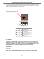
1
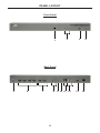
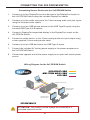
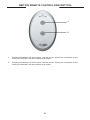
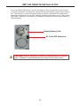
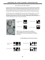
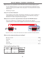
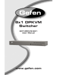
2x2 DPKVM
Switch
EXT-DPKVM-422
User Manual
www.gefen.com
ASKING FOR ASSISTANCE
Technical Support:
Telephone
Fax
(818) 772-9100
(800) 545-6900
(818) 772-9120
Technical Support Hours:
8:00 AM to 5:00 PM Monday thru Friday.
Write To:
Gefen LLC
c/o Customer Service
20600 Nordhoff St
Chatsworth, CA 91311
www.gefen.com
[email protected]
Notice
Gefen, LLC reserves the right to make changes in the hardware, packaging, and
any accompanying documentation without prior written notice.
2x2 DPKVM Switch is a trademark of Gefen, LLC
© 2011 Gefen, LLC. All rights reserved.
All trademarks are the property of their respective owners.
Rev A2
CONTENTS
1
Introduction
2
Operation Notes
3
Features
4
Panel Layout
5
Panel Descriptions
6
Connecting the 2x2 DPKVM Switch
7
Operating the 2x2 DPKVM Switch
8
RMT-2IR Remote Control Description
9
RMT-21IR Remote Installation
10 Infared (IR) Code Channel Configuration
11 RS-232 Serial Control Interface
12 Additional Switching Options
13 Specifications
14 Warranty
INTRODUCTION
Congratulations on your purchase of the 2x2 DPKVM Switch. Your complete
satisfaction is very important to us.
Gefen
Gefen delivers innovative, progressive computer and electronics add-on solutions
that harness integration, extension, distribution and conversion technologies.
Gefen’s reliable, plug-and-play products supplement cross-platform computer
systems, professional audio/video environments and HDTV systems of all sizes
with hard-working solutions that are easy to implement and simple to operate.
The Gefen 2x2 DPKVM Switch
Switch between two computers (each using two graphic DisplayPort outputs)
effortlessly, using the Gefen 2x2 DPKVM Switch. With the output utilizing two
displays and two USB 2.0 ports, users can switch audio, video and USB for each
computer. Access two computers from one workstation without having to use a
network. Switch through the front panel “select” button, using the supplied IR
remote control, the RS-232 serial port, or the IP control. The 2x2 DPKVM Switch
is compatible with all operating systems using DisplayPort and USB.
How It Works
Connect two DisplayPort high-definition displays, USB 2.0 keyboard/mouse, or
other USB 2.0 peripherals to the 2x2 DisplayPort KVM Switch output. Connect
the DisplayPort, USB and audio ports on both computers to the 2x2 DPKVM
Switch input using the supplied cables.
1
OPERATION NOTES
READ THESE NOTES BEFORE INSTALLING OR
OPERATING THE 2X2 DPKVM SWITCH
•
The 2x2 DPKVM Switch supports Pass-through EDID. The Switch will use
the EDID from the currently active input.
•
Dual Link resolutions up to 2560 x 1600 are supported.
2
FEATURES
Features
•
Switches two high-definition displays between two DisplayPort-equipped
computers with audio/video and USB peripherals
•
Switches up to 2560 x 1600 resolution
•
Supports RGB and YCbCr color spaces
•
Rack mountable
•
Save space on your desktop Supports
Package Includes
(1) 2x2 DPKVM Switch
(4) 6 ft. DisplayPort Cables
(2) 6 ft. USB 2.0 Cables
(2) 6 ft. 3.5mm Mini-Stereo Audio cables
(1) 5V DC Locking Power Supply
(1) IR Remote Control
(1) AC Power Cable
(1) Set of Rack Ears
(1) Quick-Start Guide
3
PANEL LAYOUT
Front Panel
1
2
3
4
Back Panel
5
6
8
7
4
9 10 11 12
13
14
PANEL DESCRIPTIONS
1
I/R Receiver
Receives I/R signal from the handheld Infrared remote control unit included with the 2x2
DVI KVM Switch.
2
LED Input Status Indicator 1 & 2
This currently selected source input will be indicated with an active LED.
3
Input Selector Button
Pressing this button will cycle the input, 1 or 2, which will be selected for output.
4
Power Indicator
This LED indicator will glow bright red when the power is turned on.
5
5V DC Locking Power Connector
Connect the included 5V DC locking power supply to this connector.
6
DisplayPort Input
This port will accept a single standard DisplayPort source device. Four ports are available
for use.
7
DisplayPort Output
This port will accept a single standard DisplayPort output device. The currently selected
DisplayPort input source will be output via this port.
8
Audio Input Connector (3.5 mm Mini Stereo)
Connect audio source device to this port using the 3.5mm mini stereo cable. There are
two ports available and they are associated with display port inputs 1 & 2 respetively.
9
Audio Output Connector (3.5mm Mini Stereo):
Connect Audio devices to these ports usin 3.5 mm mini-stereo cables. Audio will output for
the currently selected input source.
10
IR Extender Port:
Connect IR extender reciever (EXT-RMT-EXT-IR) to this port.
11
USB Out Port (1-2):
Connect USB devices to these ports. There will be two ports available for simultaneous
connection of the two USB devices.
12 USB In Port (1-2):
Connect USB source devices to these ports. There are two ports available for use and
are associated with DisplayPort inputs 1 & 2, respecitvely.
13
RS-232 Serial Port
This port is used for serial communication using and RS-232 controll deviice. For more
details, refer to page 16.
14
Console Control Switch Port
This port is used for contact closure-type remote control.
5
CONNECTING THE 2X2 DPKVM SWITCH
Connecting Source Devices to the 2x2 DPKVM Switch
1.
Connect up to two DisplayPort source devices to the DisplayPort inputs on
the 2x2 DPKVM Switch using the included DisplayPort cables.
2.
Connect up to two audio sources to the 3.5mm analog audio mini-jack inputs
using the included audio cables.
3.
Connect up to two USB source devices to the USB Type B inputs using the
included USB Type A to B cables.
4.
Connect a DisplayPort supported display to the DisplayPort output on the
2x2 DPKVM Switch.
5.
Connect an audio device to the 3.5mm analog audio mini-jack output using
a user supplied 3.5mm analog audio cable.
6.
Connect up to two USB devices to the USB Type A inputs.
7.
Connect the included 5V locking power supply to the power receptacle on
the 2x2 DPKVM Switch
8.
Connect the opposite end of the power supply to an open wall socket power
source.
Wiring Diagram for the 2x2 DPKVM Switch
DISPLAYPORT CABLE
MINI STEREO AUDIO CABLE
USB CABLE
DisplayPort KVM Switcher
Displ
Computer
Computer
DisplayPort Display
w/USB & Audio
DisplayPort Display
w/USB & Audio
EXT-DPKVM-422
ATTENTION: This product should always be connected to a
grounded electrical socket.
6
OPERATING THE 2X2 DPKVM SWITCH
How to Operate the 2x2 DPKVM Switch
Switching can be accomplished via the front panel selector button, infrared
(IR) remote control, or the RS-232 communications port. Additional switching
options can be found on page 12
1
For information on switching via the front panel selector button, please see
this page.
2
For information on switching via the infrared (IR) remote control, please see
page 8.
3
For information on switching via RS-232 serial communications, please see
page 11.
Switching - Front Panel Selector Button
Switching can be accomplished via the front panel selector button. This
button will alternate between Inputs 1 & 2. Each press of this button will
change the selected input.
Front Panel Input Selector
7
RMT-2IR REMOTE CONTROL DESCRIPTION
1
2
1
Pressing this button will select Input 1 as the source. All devices connected to the
input ports labeled 1 will be selected and output.
2
Pressing this button will select Input 2 as the source. All devices connected to the
input ports labeled 2 will be selected and output.
8
RMT-2IR REMOTE INSTALLATION
To use the RMT-2IR remote, remove the battery cover on the back of the remote
to reveal the battery compartment. Insert the included battery into the open battery
slot. The positive (+) side should be facing up. Ensure that both DIP (Dual Inline
Package) switches are in the OFF position. Replace the battery cover. The remote
ships with 2 batteries. One battery is needed for operation and the other battery is
complimentary.
Empty Battery Slot
IR Code DIP Switches
CAUTION: Risk of explosion if battery is replaced by an incorrect
type. Dispose of used batteries according to the instructions.
9
INFRARED (IR) CODE CHANNEL CONFIGURATION
How to Resolve IR Code Conflicts
In the event that IR commands from other remote controls conflict with the supplied
RMT-2IR remote control, changing the remote channel will alleviate this issue. The
RMT-2IR remote control and the 2x2 DPKVM Switch both have banks of DIP (Dual
Inline Package) switches for configuring the remote channel that both units use to
communicate. These settings must exactly match each other for proper operation.
The DIP switch bank on the RMT-2IR is located underneath the battery cover. DIP
switch banks for the 2x2 DPKVM Switch are located on the underside of the unit
beneath a black piece of metallic tape. Switches 1 and 2 on the RMT-2IR directly
correspond to DIP Switches 1 and 2 on the 2x2 DPKVM Switch. Only switches 1 and
2 (of 4 in that bank) are used for IR Code settings.
Remote Channel 0:
Default
Remote Channel 1:
1
2
Remote Channel 2:
1
2
1
2
Remote Channel 3:
1
2
Left: Picture of the opened rear battery
compartment of the IR remote showing the
exposed DIP Switch bank between the battery
chambers.
2x2 DPKVM Switch DIP Switch Settings
Remote Channel 1:
Default
Remote Channel 2:
1
2
3
4
Remote Channel 3:
1
2
1
2
3
4
Remote Channel 4:
1
2
3
4
10
3
4
RS-232 SERIAL CONTROL INTERFACE
What features are available via the RS-232 serial communications port?
The 2x2 DPKVM Switch can accept commands through the RS-232 serial
communications port located on the rear panel. The current RS-232 control
features are:
•
Switching of inputs.
How do I use these features?
These features were initially intended for utilization by custom installers in
automated setups. However, these features can be tested by using any
Windows PC with the Hyperterminal program.
What pins are used for communication with the 2x2 DPKVM Switch?
Only pins 2 (Receive), 3 (Transmit), and 5 (Ground) are used for
communication. A null-modem adapter should not be used with this product.
54321
12345
9876
6789
Only Pins 2 (RX), 3 (TX), and 5 (Ground) are used on the RS-232 serial interface
What are the communication port settings?
Bits per second ..................................................................................... 19200
Data bits ....................................................................................................... 8
Parity ...................................................................................................... None
Stop bits ......................................................................................................1
Flow Control .......................................................................................... None
Switching/Routing Binary Table
ASCII
RMT-2IR Button
Binary
1
1
00110001
2
2
00110010
11
ADDITIONAL SWITCHING OPTIONS
The underside of the 2x2 DPKVM Switch features a DIP switch bank that is used to
configure additional features. DIP switch 3 is used to control the function of Contact
Closure-type remote controls on the rear panel.
This port can be configured to accept
additional switching devices
ON
OFF
1
2
3
4
1
IR Channel
2
IR Channel
3
Remote/Closure
4
Not Used
DIP Switch 3
Enabling DIP switch 3 will allow the user to utilize a contact closure type
of remote control such as Gefen product # EXT-RMT-2x2 to initiate input
switching. By default, this switch is in the OFF position and will rely on the
standard switching methods outlined previously in this manual.
DIP Switch 4
Not Used
Note: After resetting DIP switches, the unit must be power-cycled.
12
SPECIFICATIONS
Input Connector....................................................(4) DisplayPort (from computers)
Output Connector...........................................................(2) DisplayPort (to display)
Input Connector..........................................(2) USB 2.0 Type “B” (from computers)
Output Connector..................................(2) USB 2.0 Type “A” (to keyboard/mouse)
Input Connector...............................(2) 3.5mm analog L/R audio (from computers)
Output Connector................(1) 3.5mm analog L/R audio (to speakers or amplifier)
Color Spaces.................................................................................RGB and YCbCr
Dimensions..................................................................... 8.41”W x 1.57”H x 4.23”D
13
WARRANTY
Gefen warrants the equipment it manufactures to be free from defects in material
and workmanship.
If equipment fails because of such defects and Gefen is notified within two (2)
years from the date of shipment, Gefen will, at its option, repair or replace the
equipment, provided that the equipment has not been subjected to mechanical,
electrical, or other abuse or modifications. Equipment that fails under conditions
other than those covered will be repaired at the current price of parts and labor in
effect at the time of repair. Such repairs are warranted for ninety (90) days from
the day of reshipment to the Buyer.
This warranty is in lieu of all other warranties expressed or implied, including
without limitation, any implied warranty or merchantability or fitness for any
particular purpose, all of which are expressly disclaimed.
1.
Proof of sale may be required in order to claim warranty.
2.
Customers outside the US are responsible for shipping charges to and from
Gefen.
3.
Copper cables are limited to a 30 day warranty and cables must be in their
original condition.
The information in this manual has been carefully checked and is believed to
be accurate. However, Gefen assumes no responsibility for any inaccuracies
that may be contained in this manual. In no event will Gefen be liable for
direct, indirect, special, incidental, or consequential damages resulting from
any defect or omission in this manual, even if advised of the possibility of such
damages. The technical information contained herein regarding the features and
specifications is subject to change without notice.
For the latest warranty coverage information, refer to the Warranty and Return
Policy under the Support section of the Gefen Web site at www.gefen.com.
PRODUCT REGISTRATION
Please register your product online by visiting the Register Product page
under the Support section of the Gefen Web site.
14
Rev A2
20600 Nordhoff St., Chatsworth CA 91311
1-800-545-6900
818-772-9100
www.gefen.com
Pb
This product uses UL or CE listed power supplies.
fax: 818-772-9120
[email protected]