1
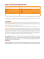
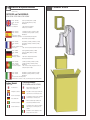
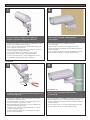
© 2012, Moog Videolarm, Inc. All Rights Reserved FCH Series Rugged Environmental Camera Enclosure Housings www.moogvideolarm.com Installation and Operation Instructions for the following models: FCH11CW Environmental housing with feed-thru wall / pole mount FCH11C2W Environmental housing with feed-thru wall / pole mount, 24Vac or 12Vdc input, heater/ blower FCH11C2WY Environmental housing with feed-thru wall / pole mount, 24Vac or 12Vdc input, heater / blower, adjustable sunshield FCH11C8WY FCH11C2WQ FCH11C8WQ Environmental housing with feed-thru wall/pole mount, dynamic power allocation PoE input, 30 watt midspan included, heater & blower, supports .at PoE cameras, adjustable sunshield Environmental housing with heat exchanger, feed-thru wall / pole mount, 24Vac or 12Vdc input, heater & blower Environmental housing with heat exchanger, feed-thru wall / pole mount, dynamic power allocation PoE input, 30 watt midspan included, heater & blower, sunshield, supports .at PoE cameras Before attempting to connect or operate this product, please read these instructions completely. 81-IN5484 02-29-2012 IMPORTANT SAFEGUARDS 1 Read these instructions. 2 Keep these instructions. 3 Heed all warnings 4 Follow all instructions. 5 Do not use this apparatus near water. 6 Clean only with damp cloth. 7 CAUTION RISK OF ELECTRIC SHOCK DO NOT OPEN Do not block any of the ventilation openings. Install in accordance with the manufacturers instructions. 8 9 SAFETY PRECAUTIONS Cable Runs- All cable runs must be within permissible distance. CAUTION: TO REDUCE THE RISK OF ELECTRIC SHOCK, DO NOT REMOVE COVER ( OR BACK). NO USER- SERVICEABLE PARTS INSIDE. REFER SEVICING TO QUALIFIED SERVICE PERSONNEL. Mounting - This unit must be properly and securely mounted to a supporting structure capable of sustaining the weight of the unit. Accordingly: a. The installation should be made by a qualified installer. b. The installation should be in compliance with local codes. c. Care should be exercised to select suitable hardware to install the unit, taking into account both the composition of the mounting surface and the weight of the unit. 10 Do not install near any heat sources such as radiators, heat registers, stoves, or other apparatus ( including amplifiers) that produce heat. 11 Do not defeat the safety purpose of the polarized or grounding-type plug. A polarized plug has two blades with one wider than the other. A grounding type plug has two blades and a third grounding prong. The wide blade or the third prong are provided for your safety. When the provided plug does not fit into your outlet, consult an electrician for replacement of the obsolete outlet. 12 Protect the power cord from being walked on or pinched particularly at plugs, convenience receptacles, and the point where they exit from the apparatus. 13 Only use attachment/ accessories specified by the manufacturer. 14 Use only with a cart, stand, tripod, bracket, or table specified by the manufacturer, or sold with the apparatus. When a cart is used, use caution when moving the cart/ apparatus combination to avoid injury from tip-over. 15 Unplug this apparatus during lighting storms or when unused for long periods of time. 16 Refer all servicing to qualified service personnel. Servicing is required when the apparatus has been damaged in any way, such as power-supply cord or plug is damaged, liquid has been spilled of objects have fallen into the apparatus, the The lightning flash with an arrowhead symbol, within an equilateral triangle, is intended to alert the user to the presence of non-insulated “dangerous voltage” within the product’s enclosure that may be of sufficient magnitude to constitute a risk to persons. Este símbolo se piensa para alertar al usuario a la presencia del “voltaje peligroso no-aisIado” dentro del recinto de los productos que puede ser un riesgo de choque eléctrico. Ce symbole est prévu pour alerter I’utilisateur à la presence “de la tension dangereuse” non-isolée dans la clôture de produits qui peut être un risque de choc électrique. Dieses Symbol soll den Benutzer zum Vorhandensein der nicht-lsolier “Gefährdungsspannung” innerhalb der Produkteinschließung alarmieren die eine Gefahr des elektrischen Schlages sein kann. Este símbolo é pretendido alertar o usuário à presença “di tensão perigosa non-isolada” dentro do cerco dos produtos que pode ser um risco de choque elétrico. Questo simbolo è inteso per avvertire I’utente alla presenza “di tensione pericolosa” non-isolata all’interno della recinzione dei prodotti che può essere un rischio di scossa elettrica. apparatus has been exposed to rain or moisture, does not operate normally, or has been dropped. Be sure to periodically examine the unit and the supporting structure to make sure that the integrity of the installation is intact. Failure to comply with the foregoing could result in the unit separating from the support structure and falling, with resultant damages or injury to anyone or anything struck by the falling unit. UNPACKING Unpack carefully. Electronic components can be damaged if improperly handled or dropped. If an item appears to have been damaged in shipment, replace it properly in its carton and notify the shipper. Be sure to save: 1 The shipping carton and packaging material. They are the safest material in which to make future shipments of the equipment. 2 These Installation and Operating Instructions. SERVICE If technical support or service is needed, contact us at the following number: TECHNICAL SUPPORT AVAILABLE 24 HOURS 1 - 800 - 554 -1124 The exclamation point within an equilateral triangle is intended to alert the user to presence of important operating and maintenance (servicing) instructions in the literature accompanying the appliance. Este símbolo del punto del exclamation se piensa para alertar al usuario a la presencia de instrucciones importantes en la literatura que acompaña la aplicación. Ce symbole de point d’exclamation est prévu pour alerter l’utilisateur à la presence des instructions importantes dans la littérature accompagnant l’appareil. Dieses Ausruf Punktsymbol soll den Benutzer zum Vorhandensein de wichtigen Anweisungen in der Literatur alarmieren, die das Gerät begleitet. Este símbolo do ponto do exclamation é pretendido alertar o usuário à presença de instruções importantes na literatura que acompanha o dispositivo. Questo simbolo del punto del exclamaton è inteso per avvertire l’utente alla presenza delle istruzioni importanti nella letteratura che accompagna l'apparecchio. Limited Warranty for Moog Videolarm Products Moog Videolarm warrants these products to be free from defects in material or workmanship as follows: PRODUCT CATEGORY PARTS \ LABOR AllEnclosuresandElectronics* Five(5)Years Poles/PolEvators™/CamEvator Three(3)Years WarriorSeries™/Q-View™/IRIlluminators Five(5)Years SViewSeries™ Five(5)Years**6monthsifusedinautoscan/touroperation Controllers Five(5)Years PowerSupplies Five(5)Years EcoKit Three(3)Years AccessoryBrackets Five(5)Years LibertyDome Three(3)Years *DeputyDome™,NiteTrac™,IglooDome,PurgeDome™ Three(3)Years**6monthsifusedinautoscan/touroperation During the labor warranty period, to repair the Product, Purchaser will either return the defective product, freight prepaid, or deliver it to Moog Videolarm Inc. Decatur GA. The Product to be repaired is to be returned in either its original carton or a similar package affording an equal degree of protection with a RMA # (Return Materials Authorization number) displayed on the outer box or packing slip. To obtain a RMA# you must contact our Technical Support Team at 800.554.1124, extension 101. Moog Videolarm will return the repaired Product freight prepaid to Purchaser. Moog Videolarm is not obligated to provide Purchaser with a substitute unit during the warranty period or at any time. After the applicable warranty period, Purchaser must pay all labor and/or parts charges. The limited warranty stated in these product instructions is subject to all of the following terms and conditions. TERMS AND CONDITIONS 1. NOTIFICATION OF CLAIMS: WARRANTY SERVICE: If Purchaser believes that the Product is defective in material or workmanship, then written notice with an explanation of the claim shall be given promptly by Purchaser to Moog Videolarm. All claims for warranty service must be made within the warranty period. If after investigation Moog Videolarm determines the reported problem was not covered by the warranty, Purchaser shall pay Moog Videolarm for the cost of investigating the problem at its then prevailing per incident billable rate. No repair or replacement of any Product or part thereof shall extend the warranty period of the entire Product. The specific warranty on the repaired part only shall be in effect for a period of ninety (90) days following the repair or replacement of that part or the remaining period of the Product parts warranty, whichever is greater. 2. EXCLUSIVE REMEDY: ACCEPTANCE: Purchaser’s exclusive remedy and Moog Videolarm’s sole obligation is to supply (or pay for) all labor necessary to repair any Product found to be defective within the warranty period and to supply, at no extra charge, new or rebuilt replacements for defective parts. 3. EXCEPTIONS TO LIMITED WARRANTY:Moog Videolarm shall have no liability or obligation to Purchaser with respect to any Product requiring service during the warranty period which is subjected to any of the following: abuse, improper use, negligence, accident, lightning damage or other acts of God (i.e., hurricanes, earthquakes), modification, failure of the end-user to follow the directions outlined in the product instructions, failure of the end-user to follow the maintenance procedures recommended by the International Security Industry Organization, written in product instructions, or recommended in the service manual for the Product. Furthermore, Moog Videolarm shall have no liability where a schedule is specified for regular replacement or maintenance or cleaning of certain parts (based on usage) and the end-user has failed to follow such schedule; attempted repair by non-qualified personnel; operation of the Product outside of the published environmental and electrical parameters, or if such Product’s original identification (trademark, serial number) markings have been defaced, altered, or removed. Moog Videolarm excludes from warranty coverage Products sold AS IS and/or WITH ALL FAULTS and excludes used Products which have not been sold by Moog Videolarm to the Purchaser. All software and accompanying documentation furnished with, or as part of the Product is furnished “AS IS” (i.e., without any warranty of any kind), except where expressly provided otherwise in any documentation or license agreement furnished with the Product. Any cost associated with removal of defective product and installation of replacement product is not included in this warranty. 4. PROOF OF PURCHASE:The Purchaser’s dated bill of sale must be retained as evidence of the date of purchase and to establish warranty eligibility. DISCLAIMER OF WARRANTY EXCEPT FOR THE FOREGOING WARRANTIES, Moog Videolarm HEREBY DISCLAIMS AND EXCLUDES ALL OTHER WARRANTIES, EXPRESS OR IMPLIED, INCLUDING, BUT NOT LIMITED TO ANY AND/OR ALL IMPLIED WARRANTIES OF MERCHANTABILITY, FITNESS FOR A PARTICULAR PURPOSE AND/OR ANY WARRANTY WITH REGARD TO ANY CLAIM OF INFRINGEMENT THAT MAY BE PROVIDED IN SECTION 2-312(3) OF THE UNIFORM COMMERCIAL CODE AND/OR IN ANY OTHER COMPARABLE STATE STATUTE. Moog Videolarm HEREBY DISCLAIMS ANY REPRESENTATIONS OR WARRANTY THAT THE PRODUCT IS COMPATIBLE WITH ANY COMBINATION OF NON-Moog Videolarm PRODUCTS OR NON-Moog Videolarm RECOMMENDED PRODUCTS PURCHASER MAY CHOOSE TO CONNECT TO THE PRODUCT. LIMITATION OF LIABILITY THE LIABILITY OF Moog Videolarm, IF ANY, AND PURCHASER’S SOLE AND EXCLUSIVE REMEDY FOR DAMAGES FOR ANY CLAIM OF ANY KIND WHATSOEVER, REGARDLESS OF THE LEGAL THEORY AND WHETHER ARISING IN TORT OR CONTRACT, SHALL NOT BE GREATER THAN THE ACTUAL PURCHASE PRICE OF THE PRODUCT WITH RESPECT TO WHICH SUCH CLAIM IS MADE. IN NO EVENT SHALL Moog Videolarm BE LIABLE TO PURCHASER FOR ANY SPECIAL, INDIRECT, INCIDENTAL, OR CONSEQUENTIAL DAMAGES OF ANY KIND INCLUDING, BUT NOT LIMITED TO, COMPENSATION, REIMBURSEMENT OR DAMAGES ON ACCOUNT OF THE LOSS OF PRESENT OR PROSPECTIVE PROFITS OR FOR ANY OTHER REASON WHATSOEVER. ! Electrical Specifications Contents of Box FCH11 Series Power 24Vac / 12Vdc Class 2 Only OUTDOOR and PoE MODELS: FCH11C2W / FCH112WY / FCH11C8WY English Español Français 24Vac: 26 watts 12Vdc: 10 watts PoE: Camera Power: Tools Required: 24Vac: 26 watts Réchauffeur (25 watts), ventilateur (1 watt) 12Vdc: 10 watts Réchauffeur (9 watts), ventilateur (1 watt) PoE : IEEE802.at Puissance d'appareil-photo: Outils requis : .100 » tournevis principal plat Tournevis phillips 24Vac: 26 watts 12Vdc: 10 watts Ponto de entrada: Ferramentas exigidas: Portuguese FCH11CW No Electronics English Français Deutsch Portuguese Italiano Heizung (25 Watt), Gebläse (1 Watt) Heizung (9 Watt), Gebläse (1 Watt) IEEE802.at .100“ flacher Hauptschraubenzieher Kreuzkopfschraubenzieher Calefator (25 watts), ventilador (1 watt) Calefator (9 watts), ventilador (1 watt) IEEE802.at .100” chave de fenda principal lisa Chave de fenda principal de Phillips 24Vac: 26 watt Riscaldatore (25 watt), ventilatore (1 watt) 12Vdc: 10 watt Riscaldatore (9 watt), ventilatore (1 watt) PoE: IEEE802.at Potere della macchina fotografica: Gli attrezzi hanno richiesto: .100„ cacciaviti capi piani Cacciavite phillips Indoor Model: Español .100” Flat head screwdriver Phillips head screwdriver 24Vac: 26 vatios Calentador (25 vatios), soplador (1 vatio) 12Vdc: 10 vatios Calentador (9 vatios), soplador (1 vatio) PoE: IEEE802.at Energía de la cámara: Herramientas requeridas: .100” destornillador principal plano Destornillador principal Phillips 24Vac: 26 Watt 12Vdc: 10 Watt PoE: Kamera-Energie: Werkzeuge erfordert: Deutsch Italiano Heater (25 watts), Blower (1 watt) Heater (9 watts), Blower (1 watt) IEEE802.at Thermiq· Models: FCH11C8WQ and FCH11C2WQ English Ninguna electrónica Español El soplador externo agrega 3.5W a las especificaciones al aire libre/del PoE Français Le ventilateur externe ajoute 3.5W aux caractéristiques extérieures/PoE Aucune électronique Keine Elektronik Nenhuma eletrônica Nessun'elettronica External blower adds 3.5W to the Outdoor / PoE specifications Deutsch Portuguese Italiano Externes Gebläse fügt 3.5W den im Freien/PoE-Spezifikationen hinzu O ventilador externo adiciona 3.5W às especificações ao ar livre/ponto de entrada Il ventilatore esterno aggiunge 3.5W alle specifiche PoE/esterne * NOT included with E or 12V models NOTE: THE FOLLOWING INSTRUCTIONS MAINLY SHOW THE FCH11C2W, BUT THESE INSTRUCTIONS ARE APPLICABLE TO ALL FCH11 MODELS. WALL MOUNTING 1 2 If you are running a conduit to the housing, first install the appropriate fitting to the wall mount. Attach mount to wall with suitable hardware (not provided). • Si usted está funcionando con un conducto a la cubierta, primero instale la guarnición apropiada al montaje de la pared. • Ate el montaje a la pared con el hardware conveniente (no proporcionado). • Si vous courez un conduit au logement, installez d'abord l'ajustage de précision approprié sur le bâti de mur. • Attachez le bâti au mur avec le matériel approprié (non fourni). • Wenn Sie ein Rohr zum Gehäuse laufen lassen, bringen Sie zuerst die passende Befestigung zur Wandeinfassung an. • Se você está funcionando uma canalização à carcaça, instale primeiramente o encaixe apropriado à montagem da parede. • Bringen Sie Einfassung zur Wand mit der verwendbaren Hardware an (nicht bereitgestellt). • Una a montagem à parede com a ferragem apropriada (não fornecida). • Attacchi il supporto alla parete con fissaggi adatti (non forniti). • Se stiate facendo funzionare un condotto all'alloggiamento, in primo luogo installi il montaggio adatto al supporto della parete. POLE MOUNTING 4 3 TAB TAB * Max Strap Width: 0.75” If attaching to pole, first break away tabs with pliers and remove (4) strap plugs. Attach mount to pole with suitable hardware (not provided). • Si atan al poste, el primeros rompen lejos lengüetas con los alicates y quitan (4) los enchufes de la correa. • Ate el montaje al poste con el hardware conveniente (no proporcionado). • Si attachant au poteau, les premiers cassent loin des étiquettes avec des pinces et enlèvent (4) des prises de courroie. • Bringen Sie Einfassung zum Pfosten mit der verwendbaren Hardware an (nicht bereitgestellt). • Una a montagem ao pólo com a ferragem apropriada (não fornecida). • Bei der Befestigung zum Pfosten, brechen erste weg Vorsprünge mit Zangen und entfernen (4) Bügelstecker. • Se unindo ao pólo, o primeiros quebram afastado abas com alicates e removem (4) plugues da cinta. • Se attaccando al palo, i primi rompono via le linguette con le pinze e rimuovono (4) la cinghia tappa. • Attachez le bâti au poteau avec le matériel approprié (non fourni). • Attacchi il supporto al palo con fissaggi adatti (non forniti). 5 Hinge housing away from mount by loosening (2) rear screws. • Abisagre la cubierta lejos del montaje aflojando (2) los tornillos posteriores. • Articulez le logement à partir du bâti en desserrant (2) les vis arrière. • Lagern Sie Gehäuse weg von Einfassung schwenkbar, indem Sie (2) hintere Schrauben lösen. • Articule a carcaça longe da montagem afrouxando (2) os parafusos traseiros. • Alloggiamento della cerniera a partire dal supporto allentando (2) viti posteriori. 6 Run cables through mount either by conduit input or through the back of the mount. • Funcione con los cables montan a través por el conducto entrado o a través de la parte posterior del montaje. • Courez les câbles montent à travers par le conduit entré ou par le dos du bâti. • Laufen lassen Sie Kabel anbringen durch entweder durch das eingegebene Rohr oder durch die Rückseite der Einfassung. • Funcione cabos montam completamente pela canalização entrada ou através da parte traseira da montagem. • Faccia funzionare i cavi attraverso montano dal condotto immesso o tramite la parte posteriore del supporto. 7 8 Pass cables through wiring membranes (use screwdriver to pierce). Hinge the housing closed and tighten (2) rear screws. . • Pase los cables a través de las membranas del cableado (el destornillador del uso a perforar) . • Passez les câbles par des membranes de câblage (le tournevis d'utilisation à percer). • Führen Sie Kabel durch Verdrahtungsmembranen (zu durchbohren der Gebrauchschraubenzieher) . • Passe cabos através das membranas da fiação (a chave de fenda do uso a perfurar). . • Abisagre la cubierta cerrada y apriete (2) los tornillos posteriores. • Articulez le logement fermé et serrez (2) les vis arrière. • Lagern Sie das geschlossene Gehäuse schwenkbar und ziehen Sie (2) hintere Schrauben fest. • Articule a carcaça fechado e aperte (2) os parafusos traseiros. • Munisca l'alloggiamento di cardini chiuso e stringa (2) viti posteriori. • Passi i cavi tramite le membrane dei collegamenti (cacciavite di uso da perforare). 9 10 TAB TAB Open housing lid. Remove camera tray by squeezing tabs together. .• Abra la tapa de la cubierta. .• Quite la bandeja de la cámara exprimiendo lengüetas juntas. • Ouvrez le couvercle de logement. • Enlevez le plateau d'appareil-photo en serrant des étiquettes ensemble. • Öffnen Sie Gehäusekappe. • Entfernen Sie Kamerabehälter, indem Sie zusammen Vorsprünge zusammendrücken. • Abra a tampa da carcaça. • Apra il coperchio dell'alloggiamento. • Remova a bandeja da câmera espremendo abas junto. • Rimuova insieme il vassoio della macchina fotografica comprimendo le linguette. 11 Mount camera with ¼-20 hardware. Slide tray into place and confirm tabs are securely snapped into place. • Cámara del montaje con el ¼ - hardware 20. Resbale la bandeja dentro de lugar y confirme las lengüetas se encajan a presión con seguridad hacia lugar. • Appareil-photo de bâti avec le ¼ - matériel 20. Glissez le plateau dans l'endroit et confirmez les étiquettes sont solidement cassés dans l'endroit. • Einfassungskamera mit ¼ - Hardware 20. Schieben Sie Behälter in Platz und bestätigen Sie Vorsprünge werden gerissen sicher in Platz. • Câmera da montagem com ¼ - ferragem 20. Deslize a bandeja no lugar e confirme abas são agarrados firmemente no lugar. • Macchina fotografica del supporto con ¼ - fissaggi 20. Faccia scorrere il vassoio nel posto e confermi le linguette saldamente sono schioccati nel posto. 24Vac Diagram 12 - Terminate power and data lines. - Install shunt on “24Vac” jumper as shown. - Power output to camera will be 24Vac. INCOMING POWER SHUNT • Termine las líneas de la energía y de datos. - Instale la desviación en el puente “24Vac” como se muestra. - La salida de energía a la cámara será 24Vac. • Terminez les lignes de puissance et de données. - Installez le shunt sur le pullover « 24Vac » comme montré. - Le rendement de puissance à l'appareil-photo sera 24Vac. • Beenden Sie Energie und Datenleitungen. - Bringen Sie Shunt auf Überbrücker „24Vac“ wie gezeigt an. - Abgabeleistung zur Kamera ist 24Vac. • Termine linhas do poder e de dados. - Instale a derivação na ligação em ponte “24Vac” como mostrada. - A saída de poder à câmera será 24Vac. • Termini le linee di dati e di potere. - Installi lo shunt sul ponticello “24Vac„ come indicato. - L'output di forza motrice alla macchina fotografica sarà 24Vac. 12Vdc Diagram 13 - Terminate incoming voltage as shown. - Install shunt on “12Vdc” jumper as shown. - Power output to camera will be 12Vdc. INCOMING POWER SHUNT • Termine el voltaje entrante como se muestra. - Instale la desviación en el puente “12Vdc” como se muestra. - La salida de energía a la cámara será 12Vdc. • Terminez la tension entrante comme montrée. - Installez le shunt sur le pullover « 12Vdc » comme montré. - Le rendement de puissance à l'appareil-photo sera 12Vdc. • Beenden Sie ankommende Spannung wie gezeigt. - Bringen Sie Shunt auf Überbrücker „12Vdc“ wie gezeigt an. - Abgabeleistung zur Kamera ist 12Vdc. • Termine a tensão entrante como mostrada. - Instale a derivação na ligação em ponte “12Vdc” como mostrada. - A saída de poder à câmera será 12Vdc. • Termini la tensione ricevuta come indicata. - Installi lo shunt sul ponticello “12Vdc„ come indicato. - L'output di forza motrice alla macchina fotografica sarà 12Vdc. 14 Adjust the aim of the housing by loosening the screw on the mount arm. .• Ajuste la puntería de la cubierta aflojando el tornillo en el brazo del montaje. 15 After powering your system up, make necessary focus and camera adjustments. .• Después de accionar su sistema para arriba, haga los ajustes necesarios del foco y de la cámara. • Ajustez le but du logement en desserrant la vis sur le bras de bâti. • Après avoir mis votre système, faites les ajustements nécessaires de foyer et d'appareil-photo. • Justieren Sie das Ziel des Gehäuses, indem Sie die Schraube am Einfassungsarm lösen. • Nachdem Sie oben Ihr System angetrieben haben, nehmen Sie notwendige Fokus- und Kamerajustagen vor. • Ajuste o alvo da carcaça afrouxando o parafuso no braço da montagem. • Após ter psto seu sistema acima, faça ajustes necessários do foco e da câmera. • Registri lo scopo dell'alloggiamento allentando la vite sul braccio del supporto. • Dopo la potenza del vostro sistema in su, procedi alle registrazioni necessarie della macchina fotografica e del fuoco. 16 Close the housing lid and securely tighten the (2) lid screws. 17 The camera tray can be securely locked into place with the provided 3.5 x 7mm screw. Tighten it through the rear tray tab. .• La bandeja de la cámara se puede trabar con seguridad en lugar con el .• Cierre la tapa de la cubierta y apriete con seguridad (2) los tornillos • • Fermez le couvercle de logement et serrez solidement (2) les vis de couvercle. • • Schließen Sie die Gehäusekappe und ziehen Sie sicher die (2) Kappenschrauben fest. • de la tapa. • Feche a tampa da carcaça e aperte firmemente (2) os parafusos da tampa. • Chiuda il coperchio dell'alloggiamento e saldamente stringa (2) il coperchio avvita. 18 • tornillo proporcionado de 3.5 x de 7m m. Apriétela a través de la lengüeta posterior de la bandeja. Le plateau d'appareil-photo peut être solidement fermé à clef sur l'endroit avec la vis fournie de 3.5 x de 7mm. Serrez-le par l'étiquette arrière de plateau. Der Kamerabehälter kann in Platz mit der zur Verfügung gestellten 3.5 x 7mm Schraube sicher verriegelt werden. Ziehen Sie ihn durch den hinteren Behältervorsprung fest. A bandeja da câmera pode ser firmemente fechado no lugar com o parafuso fornecido de 3.5 x de 7mm. Aperte-a através da aba traseira da bandeja. Il vassoio della macchina fotografica può essere saldamente bloccato nel posto con la vite fornita di 7mm x di 3.5. Stringalo attraverso la linguetta posteriore del vassoio. 19 Wire Gauge 5.5 10 20 30 40 50 60 70 80 If your housing has a sunshield, adjust it for your particular lighting conditions by loosening (2) screws. .• Si su cubierta tiene un sunshield, ajústelo para que haya sus condiciones de iluminación particulares aflojando (2) los tornillos. • Si votre logement a un sunshield, ajustez-le à vos états d'éclairage particuliers en desserrant (2) des vis. • Wenn Ihr Gehäuse ein sunshield hat, stellen Sie es auf Ihre bestimmten Beleuchtungzustände ein, indem Sie (2) Schrauben lösen. • Se sua carcaça tem um sunshield, ajuste-o para suas condições de iluminação particulares afrouxando (2) os parafusos. • Se il vostro alloggiamento ha un sunshield, registrilo per ottenere le vostre condizioni di luce particolari allentando (2) avvita. ,5 22 Total vA consumed ft ,75 20 1,0 18 1,5 16 2,5 14 400 m 120 600 960 121 182 292 180 300 480 800 4 12 6 10 - - 2 MM AWG 1300 36.5 54.9 91.4 146 243 396 86 141 225 358 571 905 1440 27.1 43.0 68.6 109 174 275 438 65 90 130 225 350 525 830 19.8 27.4 39.6 68.6 106 160 252 44 70 112 179 285 452 720 13.4 21.3 34.1 54.6 86.9 138 219 56 90 143 228 362 576 35 10.6 17.1 27.4 43.6 69.5 110 175 29 47 75 119 190 301 480 9.4 14.3 22.9 36.2 57.9 91.7 146 40 64 102 163 258 411 8.8 12.2 19.5 31.1 49.7 78.6 125 34 55 85 140 215 340 25 31 7.6 10.3 16.8 25.9 42.7 65.5 103 These are recommended maximum distances for 24VAC with a 10% voltage drop. • Éstos se recomiendan las distancias máximas para 24VAC con una caída de voltaje del 10%. • Ceux-ci sont recommandés des distances maximum pour 24VAC avec une chute de tension de 10%. • Diese werden maximale Abstände für 24VAC mit einem 10% Spannungsabfall empfohlen. • Estes são recomendados distâncias máximas para 24VAC com uma queda de tensão de 10%. • Questi sono suggeriti distanze massime per 24VAC con una differenza de potenziale di 10%. Replacement Parts FCH11 # 1 2 Part Number Description RPVL3948 FCH Camera Tray RPVL3950 FCH Heater + Bracket 3 RP76VL2016 FCH 12VDC/24VAC PCB 4 RPFD080 12VDC 40mm Fan 5 RPVL3953 Cable Membrane (0.60" hole) 6 RPFTM2425G FCH Wall Mount Assembly 7 RPFCH11HP FCH Hardware Packet 8 RP71VLBL09 Outdoor Rated Fan (Thermiq only) Product Registration/Warranty Thank you for choosing Moog Videolarm. We value your patronage and are solely committed to providing you with the highest quality products available and superior customer service. Should a problem arise, rest assure that Moog Videolarm stands behind its products by offering impressive warranty plans: 3 Years on all Housings, Poles, Power Supplies, and Accessories and 5 Years on camera systems (SView, QView, Warriors), and InfraRed Illuminators. Register Your Products Online Take a few moments and validate your purchase via the Online Product Registration Form at www.videolarm.com/productregistration.jsp Register your recent Moog Videolarm purchases and benefit from the following: • Simple and Trouble-Free RMA process • Added into customer database to receive product updates / news • Eliminate the need to archive original purchase documents: Receipts, Purchase Orders, etc…