1
User Guide
AOS-W Instant
6.3.1.1-4.0
Copyright
© 2013 Alcatel-Lucent. All rights reserved.
Specifications in this manual are subject to change without notice.
Originated in the USA.
AOS-W, Alcatel 4302, Alcatel 4304, Alcatel 4306, Alcatel 4308, Alcatel 4324, Alcatel 4504, Alcatel 4604, Alcatel
4704, Alcatel 6000, OAW-AP41, OAW-AP68, OAW-AP60/61/65, OAW-AP70, OAW-AP80, OAW-AP92/93, OAWAP105, OAW-AP120/121, OAW-AP124/125, OAW-AP175, OAW-IAP92/93/105, OAW-RAP2, OAW-RAP5, and
Omnivista 3600 Air Manager are trademarks of Alcatel-Lucent in the United States and certain other countries.
Any other trademarks appearing in this manual are the property of their respective companies. Includes software
from Litech Systems Design. The IF-MAP client library copyright 2011 Infoblox, Inc. All rights reserved. This product
includes software developed by Lars Fenneberg et al.
Legal Notice
The use of Alcatel-Lucent switching platforms and software, by all individuals or corporations, to terminate Cisco or
Nortel VPN client devices constitutes complete acceptance of liability by that individual or corporation for this action
and indemnifies, in full, Alcatel-Lucent from any and all legal actions that might be taken against it with respect to
infringement of copyright on behalf of Cisco Systems or Nortel Networks.
0511472-01 | November 2013
AOS-W Instant 6.3.1.1-4.0 | User Guide
Contents
Contents
3
About this Guide
25
Intended Audience
25
Related Documents
25
Conventions
25
Contacting Support
26
About AOS-W Instant
27
AOS-W Instant Overview
27
Supported Devices
27
AOS-W Instant UI
28
AOS-W Instant CLI
28
What is New in AOS-W Instant 6.3.1.1-4.0
Setting up an OAW-IAP
Setting up AOS-W Instant Network
28
32
32
Connecting an OAW-IAP
32
Assigning an IP address to the OAW-IAP
32
Assigning a Static IP
Connecting to a Provisioning Wi-Fi Network
33
33
OAW-IAP Cluster
33
Disabling the Provisioning Wi-Fi Network
34
Logging in to the AOS-W Instant UI
Specifying Country Code
34
35
Accessing the AOS-W Instant CLI
35
Connecting to a CLI Session
35
Applying Configuration Changes
36
Example:
Using Sequence Sensitive Commands
AOS-W Instant User Interface
Login Screen
AOS-W Instant 6.3.1.1-4.0 | User Guide
36
36
38
38
Contents | 3
Logging into the AOS-W Instant UI
38
Viewing Connectivity Summary
38
Language
38
Main Window
39
Banner
39
Search
39
Tabs
39
Networks Tab
40
Access Points Tab
40
Clients Tab
41
Links
4 | Contents
41
New Version Available
41
System
42
RF
43
Security
44
Maintenance
45
Help
46
More
46
VPN
46
IDS
47
Wired
48
Services
49
DHCP Server
50
Support
50
Logout
51
Monitoring
51
Info
51
RF Dashboard
53
RF Trends
54
Usage Trends
55
Mobility Trail
59
Spectrum
60
Alerts
60
AOS-W Instant 6.3.1.1-4.0 | User Guide
IDS
63
Configuration
64
AirGroup
65
OmniVista 3600 Setup
65
Pause/Resume
65
Views
Initial Configuration Tasks
Updating IP Address of an OAW-IAP
65
67
67
In the AOS-W Instant UI
67
In the CLI
68
Modifying the OAW-IAP Name
68
In the AOS-W Instant UI
68
In the CLI
69
Updating Location Details of an OAW-IAP
69
In the AOS-W Instant UI
69
In the CLI
69
Configuring External Antenna
69
EIRP and Antenna Gain
69
Configuring Antenna Gain
70
In the AOS-W Instant UI
70
In the CLI
70
Upgrading an OAW-IAP
70
Upgrading an OAW-IAP and Image Server
70
Image Management Using OmniVista
70
Image Management Using Cloud Server
71
Configuring HTTP Proxy on an OAW-IAP
71
In the AOS-W Instant UI
71
In the CLI
72
Upgrading an OAW-IAP Using Automatic Image Check
Upgrading to a New Version Manually
Upgrading an Image Using CLI
Enabling Terminal Access
AOS-W Instant 6.3.1.1-4.0 | User Guide
72
72
73
73
Contents | 5
In the AOS-W Instant UI
73
In the CLI
73
Enabling Auto Join Mode
Disabling Auto Join Mode
74
Adding an OAW-IAP to the Network
74
Removing an OAW-IAP from the Network
74
Configuring a Preferred Band
74
In the AOS-W Instant UI
74
In the CLI
75
Configuring Radio Profiles for an OAW-IAP
75
Configuring ARM Assigned Radio Profiles for an OAW-IAP
75
Configuring Radio Profiles Manually for OAW-IAP
75
In the CLI
76
Configuring Inter-user Bridging and Local Routing
76
In the AOS-W Instant UI
76
In the CLI
76
Configuring Uplink VLAN for an OAW-IAP
77
In the AOS-W Instant UI
77
In the CLI
77
Configuring an NTP Server
77
In the AOS-W Instant UI
77
In the CLI
78
Mesh OAW-IAP Configuration
Mesh Network Overview
79
79
Mesh OAW-IAPs
79
Mesh Portals
79
Mesh Points
80
Setting up AOS-W Instant Mesh Network
VLAN Configuration
6 | Contents
74
80
81
VLAN Pooling
81
Uplink VLAN Monitoring and Detection on Upstream Devices
81
AOS-W Instant 6.3.1.1-4.0 | User Guide
Virtual Controller Configuration
82
Virtual Controller Overview
82
Master Election Protocol
82
Preference to an OAW-IAP with 3G/4G Card
82
Preference to an OAW-IAP with Non-Default IP
82
Manual Provisioning of Master OAW-IAP
Provisioning an OAW-IAP as a Master OAW-IAP
82
83
In the AOS-W Instant UI
83
In the CLI
83
Virtual Controller IP Address Configuration
Configuring IP Address for Virtual Controller
83
83
In the AOS-W Instant UI
84
In the CLI
84
Wireless Network Profiles
Understanding Wireless Network Profiles
Network Types
Configuring WLAN Settings for an SSID Profile
85
85
85
86
In the AOS-W Instant UI
86
In the CLI
88
Configuring VLAN Settings for a WLAN SSID Profile
89
In the AOS-W Instant UI
89
In the CLI
90
Configuring Security Settings for a WLAN SSID Profile
Configuring Security Settings for an Employee or Voice Network
90
90
In the AOS-W Instant UI
91
In the CLI
94
Configuring Access Rules for a WLAN SSID Profile
95
In the AOS-W Instant UI
96
In the CLI
96
Configuring Support for Fast Roaming of Clients
802.11r Roaming
Configuring an OAW-IAP for 802.11r support
AOS-W Instant 6.3.1.1-4.0 | User Guide
97
97
97
Contents | 7
In the AOS-W Instant UI
97
In the CLI
98
Opportunistic Key Caching
Configuring an OAW-IAP for OKC Roaming
In the AOS-W Instant UI
In the CLI
Editing Status of a WLAN SSID Profile
99
99
99
99
In the AOS-W Instant UI
100
In the CLI
100
Configuring Additional WLAN SSIDs
100
Enabling the Extended SSID
100
In the AOS-W Instant UI
100
In the CLI
101
Editing a WLAN SSID Profile
101
Deleting a WLAN SSID Profile
101
Wired Profiles
Configuring a Wired Profile
102
102
Configuring Wired Settings
102
In the AOS-W Instant UI
102
In the CLI
103
Configuring VLAN for a Wired Profile
103
In the AOS-W Instant UI
103
In the CLI
104
Configuring Security Settings for a Wired Profile
Configuring Security Settings for a Wired Employee Network
104
104
In the AOS-W Instant UI
105
In the CLI
105
Configuring Access Rules for a Wired Profile
8 | Contents
98
105
In the AOS-W Instant UI
105
In the CLI
106
Understanding Hierarchical Deployment
107
Configuring Wired Bridging on Ethernet 0
107
AOS-W Instant 6.3.1.1-4.0 | User Guide
In the AOS-W Instant UI
108
In the CLI
108
Assigning a Profile to Ethernet Ports
108
In the AOS-W Instant UI
108
In the CLI
108
Editing a Wired Profile
108
Deleting a Wired Profile
109
Captive Portal for Guest Access
110
Understanding Captive Portal
110
Types of Captive Portal
110
Walled Garden
111
Configuring a WLAN SSID for Guest Access
111
In the AOS-W Instant UI
111
In the CLI
113
Configuring Wired Profile for Guest Access
114
In the AOS-W Instant UI
114
In the CLI
115
Configuring Internal Captive Portal for Guest Network
116
In the Instant UI
116
In the CLI
117
Configuring External Captive Portal for a Guest Network
118
External Captive Portal Profiles
118
Creating a Captive Portal Profile
118
In the AOS-W Instant UI
118
In the CLI
119
Configuring an SSID or Wired Profile to Use External Captive Portal Authentication
In the AOS-W Instant UI
In the CLI
Configuring External Captive Portal Authentication Using ClearPass Guest
120
120
121
121
Creating a Web Login page in the ClearPass Guest
121
Configuring the RADIUS Server in AOS-W Instant
121
Configuring Guest Logon Role and Access Rules for Guest Users
AOS-W Instant 6.3.1.1-4.0 | User Guide
122
Contents | 9
In the AOS-W Instant UI
122
In the CLI
122
Configuring Captive Portal Roles for an SSID
In the AOS-W Instant UI
124
In the CLI
125
Configuring Walled Garden Access
126
In the AOS-W Instant UI
126
In the CLI
126
Disabling Captive Portal Authentication
User Management
126
128
OAW-IAP Users
128
Configuring Administrator Credentials for the Virtual Controller Interface
128
In the AOS-W Instant UI
128
In the CLI
129
Configuring Guest Management Interface Administrator Credentials
130
In the AOS-W Instant UI
130
In the CLI
130
Configuring Users for Internal Database of an OAW-IAP
130
In the AOS-W Instant UI
130
In the CLI
131
Configuring the Read-Only Administrator Credentials
132
In the AOS-W Instant UI
132
In the CLI
132
Adding Guest Users through the Guest Management Interface
Authentication
132
134
Understanding Authentication Methods
134
Supported Authentication Servers
135
External RADIUS Server
RADIUS Server Authentication with VSA
10 | Contents
123
136
136
Internal RADIUS Server
136
Authentication Termination on OAW-IAP
137
Supported VSAs
137
AOS-W Instant 6.3.1.1-4.0 | User Guide
Understanding Encryption Types
141
WPA and WPA2
141
Recommended Authentication and Encryption Combinations
141
Understanding Authentication Survivability
142
Configuring Authentication Servers
144
Configuring an External Server for Authentication
144
In the AOS-W Instant UI
144
In the CLI
147
Configuring Dynamic RADIUS Proxy Parameters
Enabling Dynamic RADIUS Proxy
148
148
In the AOS-W Instant UI
148
In the CLI
149
Configuring Dynamic RADIUS Proxy Parameters for Authentication Servers
149
In the AOS-W Instant UI
149
In the CLI
149
Associate the Authentication Servers with an SSID or Wired Profile
In the CLI
Configuring Authentication Parameters for Virtual Controller Management Interface
149
150
150
In the AOS-W Instant UI
150
In the CLI
151
Configuring 802.1X Authentication for a Network Profile
Configuring 802.1X authentication for a Wireless Network Profile
151
152
In the AOS-W Instant UI
152
In the CLI
152
Configuring 802.1X authentication for Wired Profiles
153
In the AOS-W Instant UI
153
In the CLI
153
Configuring MAC Authentication for a Network Profile
Configuring MAC Authentication for Wireless Network Profiles
153
154
In the AOS-W Instant UI
154
In the CLI
154
Configuring MAC Authentication for Wired Profiles
AOS-W Instant 6.3.1.1-4.0 | User Guide
154
Contents | 11
In the AOS-W Instant UI
154
In the CLI
154
Configuring MAC Authentication with 802.1X Authentication
Configuring MAC and 802.1X Authentication for a Wireless Network Profile
155
In the AOS-W Instant UI
155
In the CLI
155
Configuring MAC and 802.1X Authentication for Wired Profiles
155
In the AOS-W Instant UI
155
In the CLI
156
Configuring MAC Authentication with Captive Portal Authentication
Configuring MAC Authentication with Captive Portal Authentication
156
156
In the AOS-W Instant UI
156
In the CLI
157
Configuring WISPr Authentication
157
In the AOS-W Instant UI
157
In the CLI
158
Blacklisting Clients
158
Blacklisting Clients Manually
159
Adding a Client to the Blacklist
159
In the AOS-W Instant UI
159
In the CLI
159
Blacklisting Users Dynamically
12 | Contents
155
159
Authentication Failure Blacklisting
159
Session Firewall Based Blacklisting
159
Configuring Blacklist Duration
159
In the AOS-W Instant UI
159
In the CLI
160
Uploading Certificates
160
Loading Certificates using AOS-W Instant UI
161
Loading Certificates using AOS-W Instant CLI
161
Loading Certificates using Omnivista
161
AOS-W Instant 6.3.1.1-4.0 | User Guide
Roles and Policies
Firewall Configuration
164
164
Configuring ALG Protocols
164
In the AOS-W Instant UI
164
In the CLI
165
Configuring Firewall Settings for Protection from ARP Attacks
166
In the AOS-W Instant UI
166
In the CLI
166
Managing Inbound Traffic
Configuring Management Subnets
167
167
In the AOS-W Instant UI
167
In the CLI
168
Configuring Restricted Access to Corporate Network
168
In the AOS-W Instant UI
168
In the CLI
168
Access Control List Rules
Configuring Access Rules
169
169
In the Instant UI
169
In the CLI
171
Configuring Network Address Translation
Configuring a Source NAT Access Rule
171
172
In the AOS-W Instant UI
172
In the CLI
172
Configuring Source-Based Routing
172
Configuring a Destination NAT Access Rule
173
In the AOS-W Instant UI
173
In the CLI
173
Configuration Examples for Access Rules
173
Allow POP3 Service to a Particular Server
174
Allow TCP Service to a Particular Network
174
Deny FTP Service except to a Particular Server
174
Deny bootp Service except to a Particular Network
175
Configuring User Roles
AOS-W Instant 6.3.1.1-4.0 | User Guide
175
Contents | 13
Creating a User Role
In the AOS-W Instant UI
175
In the CLI
176
Assigning Bandwidth Contracts to User Roles
176
Assigning Bandwidth Contracts in the AOS-W InstantUI
176
Assigning a bandwidth contract using AOS-W Instant CLI:
176
Configuring Machine and User Authentication Roles
177
In the AOS-W Instant UI
177
In the CLI
177
Configuring Derivation Rules
Understanding Role Assignment Rule
178
178
RADIUS VSA Attributes
178
MAC-Address Attribute
178
Roles Based on Client Authentication
178
DHCP Option and DHCP Fingerprinting
178
Creating a Role Derivation Rule
179
In the AOS-W Instant UI
179
In the CLI
180
Example
180
Understanding VLAN Assignment
180
Vendor Specific Attributes (VSA)
180
VLAN Assignment Based on Derivation Rules
181
User Role
182
VLANs Created for an SSID
182
Configuring VLAN Derivation Rules
182
In the AOS-W Instant UI
182
In the CLI
183
Example
183
Using Advanced Expressions in Role and VLAN Derivation Rules
Configuring a User Role for VLAN Derivation
Creating a User VLAN Role
In the AOS-W Instant UI
14 | Contents
175
184
185
185
185
AOS-W Instant 6.3.1.1-4.0 | User Guide
In the CLI
Assigning User VLAN Roles to a Network Profile
185
185
In the AOS-W Instant UI
185
In the CLI
186
Uplink Configuration
Uplink Interfaces
Ethernet Uplink
Configuring PPPoE Uplink Profile
187
187
188
189
In the AOS-W Instant UI
189
In the CLI
189
3G/4G Uplink
190
Types of Modems
190
Configuring Cellular Uplink Profiles
192
In the AOS-W Instant UI
192
In the CLI
193
Wi-Fi Uplink
194
Configuring a Wi-Fi Uplink Profile
Uplink Preferences and Switching
Enforcing Uplinks
194
196
196
In the AOS-W Instant UI
196
In the CLI
196
Setting an Uplink Priority
196
In the AOS-W Instant UI
196
In the CLI
197
Enabling Uplink Preemption
197
In the AOS-W Instant UI
197
In the CLI
197
Switching Uplinks Based on VPN and Internet Availability
197
Switching Uplinks Based on VPN Status
197
Switching Uplinks Based on Internet Availability
198
In the AOS-W Instant UI
198
In the CLI
198
Viewing Uplink Status and Configuration
AOS-W Instant 6.3.1.1-4.0 | User Guide
199
Contents | 15
Mobility and Client Management
Layer-3 Mobility Overview
200
Configuring L3-Mobility
201
Home Agent Load Balancing
201
Configuring a Mobility Domain for AOS-W Instant
201
In the AOS-W Instant UI
201
In the CLI
202
Spectrum Monitor
203
Understanding Spectrum Data
203
Device List
203
Non Wi-Fi Interferers
204
Channel Details
206
Channel Metrics
207
Spectrum Alerts
208
Configuring Spectrum Monitors and Hybrid OAW-IAPs
Converting an OAW-IAP to a Hybrid OAW-IAP
208
208
In the AOS-W Instant UI
208
In the CLI
208
Converting an OAW-IAP to a Spectrum Monitor
209
In the AOS-W Instant UI
209
In the CLI
209
Adaptive Radio Management
ARM Overview
211
211
Channel or Power Assignment
211
Voice Aware Scanning
211
Load Aware Scanning
211
Band Steering Mode
211
Client Match
211
Airtime Fairness Mode
212
Access Point Control
16 | Contents
200
212
Monitoring the Network with ARM
213
ARM Metrics
213
AOS-W Instant 6.3.1.1-4.0 | User Guide
Configuring ARM Features on an OAW-IAP
213
In the AOS-W Instant UI
213
In the CLI
216
Configuring Radio Settings for an OAW-IAP
In the AOS-W Instant UI
218
218
In the CLI
219
Intrusion Detection
221
Detecting and Classifying Rogue APs
221
OS Fingerprinting
221
Configuring Wireless Intrusion Protection and Detection Levels
222
Containment Methods
226
Configuring IDS Using CLI
226
Content Filtering
228
Content Filtering
228
Enabling Content Filtering
228
Enabling Content Filtering for a Wireless Profile
228
In the AOS-W Instant UI
228
In the CLI
228
Enabling Content Filtering for a Wired Profile
229
In the AOS-W Instant UI
229
In the CLI
229
Configuring Enterprise Domains
229
In the AOS-W Instant UI
229
In the CLI
229
Configuring OpenDNS Credentials
229
In the AOS-W Instant UI
230
In the CLI
230
DHCP Configuration
Configuring DHCP Scopes
Configuring Distributed DHCP Scopes
231
231
231
In the AOS-W Instant UI
231
In the CLI
233
AOS-W Instant 6.3.1.1-4.0 | User Guide
Contents | 17
Configuring Centralized DHCP Scope
In the AOS-W Instant UI
234
In the CLI
235
Configuring Local and Local,L3 DHCP Scopes
236
In the AOS-W Instant UI
236
In the CLI
237
Configuring DHCP Server for Client IP Assignment
238
In the AOS-W Instant UI
238
In the CLI
238
VPN Configuration
239
Understanding VPN Features
239
Configuring a Tunnel from an OAW-IAP to OmniAccess WLAN Switch
239
Configuring IPSec Tunnel
239
In the AOS-W Instant UI
239
In the CLI
240
Example
241
Enabling Automatic Configuration of GRE Tunnel
241
In the AOS-W Instant UI
241
In the CLI
243
Manually Configuring a GRE Tunnel
243
In the AOS-W Instant UI
243
In the CLI
244
Configuring an L2TPv3 Tunnel
244
In the AOS-W Instant UI
245
In the CLI
246
Example
247
Configuring Routing Profiles
250
In the AOS-W Instant UI
250
In the CLI
251
IAP-VPN Configuration
Overview
Termination of IPSec and GRE VPN Tunnels
18 | Contents
234
252
252
252
AOS-W Instant 6.3.1.1-4.0 | User Guide
L2/L3 Forwarding Modes
252
IAP-VPN Scalability Limits
253
OSPF Configuration
253
VPN Configuration
Whitelist Database Configuration
255
255
Switch Whitelist Database
255
External Whitelist Database
255
VPN Local Pool Configuration
255
Role Assignment for the Authenticated OAW-IAPs
255
VPN Profile Configuration
256
Viewing Branch Status
Example
Omnivista Integration and Management
Omnivista Features
256
256
258
258
Image Management
258
OAW-IAP and Client Monitoring
258
Template-based Configuration
258
Trending Reports
259
Intrusion Detection System
259
Wireless Intrusion Detection System (WIDS) Event Reporting to OmniVista
259
RF Visualization Support for AOS-W Instant
259
PSK-based and Certificate-based Authentication
260
Configuring Omnivista
Configuring Organization String
260
260
Shared Key
261
Configuring OmniVista Information
261
In the AOS-W Instant UI
261
In the CLI
262
Configuring for OmniVista Discovery through DHCP
262
Standard DHCP option 60 and 43 on Windows Server 2008
262
Alternate Method for Defining Vendor-Specific DHCP Options
265
AOS-W Instant 6.3.1.1-4.0 | User Guide
Contents | 19
AirGroup Configuration
AirGroup Overview
268
AirGroup with AOS-W Instant
269
AirGroup Solution
270
AirGroup Features
271
CPPM and ClearPass Guest Features
272
AirGroup Components
272
AirGroup Services
272
Configuring AirGroup and AirGroup Services on an OAW-IAP
273
In the AOS-W Instant UI
273
In the CLI
274
Configuring AirGroup and CPPM interface in AOS-W Instant
275
Creating a RADIUS Server
275
Assign a Server to AirGroup
275
Configure CPPM to Enforce Registration
275
Change of Authorization (CoA)
Integration with Security and Location Services Applications
Configuring an OAW-IAP for Analytics and Location Engine Support
275
276
276
ALE with AOS-W Instant
276
Enabling ALE Support on an OAW-IAP
276
In the AOS-W Instant UI
276
In the CLI
277
Verifying ALE Configuration on an OAW-IAP
277
Configuring an OAW-IAP for RTLS Support
277
In the AOS-W Instant UI
277
In the CLI
278
Integrating an OAW-IAP with Palo Alto Networks Firewall
20 | Contents
268
278
Integration with AOS-W Instant
279
Configuring an OAW-IAP for PAN integration
279
In the AOS-W Instant UI
279
In the CLI
280
AOS-W Instant 6.3.1.1-4.0 | User Guide
Lawful Intercept and CALEA Integration
CALEA Integration and Lawful Intercept Compliance
CALEA Server Integration
281
281
281
Traffic Flow from IAP to CALEA Server
281
Traffic Flow from IAP to CALEA Server through VPN
282
Client Traffic Replication
Configuring OAW-IAPs for CALEA Integration
Creating a CALEA Profile
283
283
283
In the AOS-W Instant UI
284
In the CLI
284
Creating an Access Rule for CALEA
284
In the AOS-W Instant UI
284
In the CLI
284
Verifying the configuration
285
Example
285
Hotspot Profiles
Understanding Hotspot Profiles
287
287
Generic Advertisement Service (GAS)
287
Access Network Query Protocol (ANQP)
288
Hotspot 2.0 Query Protocol (H2QP)
288
Information Elements (IEs) and Management Frames
288
NAI Realm List
288
Configuring Hotspot Profiles
Creating Advertisement Profiles for Hotspot Configuration
288
289
Configuring an NAI Realm Profile
289
Configuring a Venue Name Profile
291
Configuring a Network Authentication Profile
292
Configuring a Roaming Consortium Profile
293
Configuring a 3GPP Profile
293
Configuring an IP Address Availability Profile
293
Configuring a Domain Profile
293
Configuring an Operator-friendly Profile
294
AOS-W Instant 6.3.1.1-4.0 | User Guide
Contents | 21
Configuring a Connection Capability Profile
294
Configuring an Operating Class Profile
294
Configuring a WAN Metrics Profile
294
Creating a Hotspot Profile
295
Associating an Advertisement Profile to a Hotspot Profile
297
Creating a WLAN SSID and Associating Hotspot Profile
297
Sample Configuration
Extended Voice and Video
QoS for Microsoft Office OCS and Apple Facetime
301
301
Microsoft OCS
301
Apple Facetime
301
Dynamic CPU Management
302
Dynamic CPU Management
302
Configuring for Dynamic CPU Management
302
In the AOS-W Instant UI
302
In the CLI
302
Example
302
Link Aggregation Control Protocol for OAW-IAP220 Series
303
OAW-IAP Management
304
Configuring LED Display
304
In the AOS-W Instant UI
304
In the CLI
304
Backing up and Restoring OAW-IAP Configuration Data
304
Viewing Current Configuration
304
Backing up Configuration Data
304
Restoring Configuration
305
Converting an OAW-IAP to a Remote AP and Campus AP
22 | Contents
298
305
Converting an OAW-IAP to Remote AP
305
Converting an OAW-IAP using CLI
307
Converting an OAW-IAP to Campus AP
308
Converting an OAW-IAP to Standalone Mode
308
Converting an OAW-IAP using CLI
309
AOS-W Instant 6.3.1.1-4.0 | User Guide
Resetting a Remote AP or Campus AP to an OAW-IAP
309
Rebooting the OAW-IAP
309
Monitoring Devices and Logs
Configuring SNMP
311
311
SNMP Parameters for OAW-IAP
311
Configuring SNMP
312
Creating community strings for SNMPv1 and SNMPv2 Using AOS-W Instant UI
312
Creating community strings for SNMPv3 Using AOS-W Instant UI
312
Configuring SNMP Community Strings in the CLI
313
Configuring SNMP Traps
314
In the AOS-W Instant UI
314
In the CLI
314
Configuring a Syslog Server
314
In the AOS-W Instant UI
314
In the CLI
316
Configuring TFTP Dump Server
316
In the AOS-W Instant UI
316
In the CLI
316
Running Debug Commands from the AOS-W Instant UI
317
Support Commands
317
Regulatory Domain
322
Country Codes List
322
ClearPass Guest Setup
327
Testing
330
Troubleshooting
330
Terminology
331
Acronyms and Abbreviations
331
Glossary
332
AOS-W Instant 6.3.1.1-4.0 | User Guide
Contents | 23
Chapter 1
About this Guide
This User Guide describes the features supported by AOS-W Instant and provides detailed instructions for setting up
and configuring AOS-W Instant network.
Intended Audience
This guide is intended for customers who configure and use AOS-W Instant.
Related Documents
In addition to this document, the AOS-W Instant product documentation includes the following:
l
AOS-W Instant Installation Guides
l
AOS-W Instant 6.3.1.1-4.0 Quick Start Guide
l
AOS-W Instant 6.3.1.1-4.0 CLI Reference Guide
l
AOS-W Instant 6.3.1.1-4.0 MIB Reference Guide
l
AOS-W Instant 6.3.1.1-4.0 Syslog Messages Reference Guide
l
AOS-W Instant 6.3.1.1-4.0 Release Notes
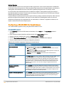
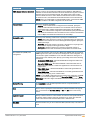
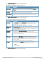
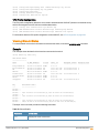
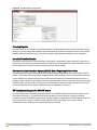
Conventions
The following conventions are used throughout this manual to emphasize important concepts:
Table 1: Typographical Conventions
Type Style
Description
Italics
This style is used to emphasize important terms and to mark the titles of books.
System items
This fixed-width font depicts the following:
Sample screen output
l System prompts
l Filenames, software devices, and specific commands when mentioned in the text.
l
Commands
In the command examples, this style depicts the keywords that must be typed exactly as
shown.
<Arguments>
In the command examples, italicized text within angle brackets represents items that you
should replace with information appropriate to your specific situation. For example:
# send <text message>
In this example, you would type “send” at the system prompt exactly as shown, followed by
the text of the message you wish to send. Do not type the angle brackets.
[Optional]
Command examples enclosed in brackets are optional. Do not type the brackets.
{Item A |
Item B}
In the command examples, items within curled braces and separated by a vertical bar
represent the available choices. Enter only one choice. Do not type the braces or bars.
AOS-W Instant 6.3.1.1-4.0 | User Guide
About this Guide | 25
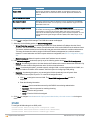
The following informational icons are used throughout this guide:
Indicates helpful suggestions, pertinent information, and important things to remember.
Indicates a risk of damage to your hardware or loss of data.
Indicates a risk of personal injury or death.
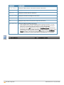
Contacting Support
Table 2: Support Information
Contact Center Online
l
Main Site
http://www.alcatel-lucent.com/enterprise
l
Support Site
https://service.esd.alcatel-lucent.com
l
Email
[email protected]
Service & Support Contact Center Telephone
l
North America
1-800-995-2696
l
Latin America
1-877-919-9526
l
EMEA
+800 00200100 (Toll Free) or +1(650)385-2193
l
Asia Pacific
+65 6240 8484
l
Worldwide
1-818-878-4507
26 | About this Guide
AOS-W Instant 6.3.1.1-4.0 | User Guide
Chapter 2
About AOS-W Instant
This chapter provides the following information:
l
AOS-W Instant Overview
l
What is New in AOS-W Instant 6.3.1.1-4.0
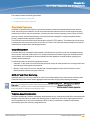
AOS-W Instant Overview
AOS-W Instant virtualizes OmniAccess WLAN Switch capabilities on 802.11 access points (APs), creating a
feature-rich enterprise-grade wireless LAN (WLAN) that combines affordability and configuration simplicity.
AOS-W Instant is a simple, easy to deploy turn-key WLAN solution consisting of one or more APs. An Ethernet port
with routable connectivity to the Internet or a self-enclosed network is used for deploying an Instant Wireless
Network. An Instant Access Point (OAW-IAP) can be installed at a single site or deployed across multiple
geographically-dispersed locations. Designed specifically for easy deployment, and proactive management of
networks. AOS-W Instant is ideal for small customers or remote locations without any on-site IT administrator.
AOS-W Instant consists of an OAW-IAP and a Virtual Controller. The Virtual Controller resides within one of the
APs. In an AOS-W Instant deployment scenario, only the first OAW-IAP needs to be configured. After the first
OAW-IAP is configured, the other OAW-IAPs inherit all the required configuration information from the Virtual
Controller. AOS-W Instant continually monitors the network to determine the OAW-IAP that should function as the
Virtual Controller at any time, and the Virtual Controller will move from one OAW-IAP to another as necessary
without impacting network performance.
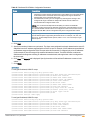
Supported Devices
The following devices are supported in the current release of AOS-W Instant:
l
OAW-IAP92
l
OAW-IAP93
l
OAW-IAP104
l
OAW-IAP105
l
OAW-IAP114
l
OAW-IAP115
l
OAW-IAP134
l
OAW-IAP135
l
OAW-IAP175P/175AC
l
OAW-RAP3WN/3WNP
l
OAW-RAP108
l
OAW-RAP109
l
OAW-RAP155/155P
l
OAW-IAP224
l
OAW-IAP225
All APs support an unlimited number of OAW-IAPs. In a network comprising of OAW-IAP92 and OAW-IAP93, an
AP can support up to 16 OAW-IAPs only.
AOS-W Instant 6.3.1.1-4.0 | User Guide
About AOS-W Instant | 27
All OAW-IAPs except OAW-IAP224, OAW-IAP225, OAW-IAP114, and OAW-IAP115 are available as the following
variants:
l
OAW-IAP-US (United States)
l
OAW-IAP-JP (Japan)
l
OAW-IAP-IL (Israel)
l
OAW-IAP-RW (Rest of World)
The OAW-IAP224, OAW-IAP225, OAW-IAP114, and OAW-IAP115 are available as the following variants:
l
OAW-IAP-US (United States)
l
OAW-IAP-RW. The RW variant also includes IL and JP variants.
For information on regulatory domains and the list of countries supported by the OAW-IAP-RW type, see:
l
Regulatory Domain on page 322
l
Country Codes List on page 322
AOS-W Instant UI
The AOS-W Instant User Interface (UI) provides a standard web based interface that allows you to configure and
monitor a Wi-Fi network. AOS-W Instant is accessible through a standard web browser from a remote management
console or workstation and can be launched using the following browsers:
l
Internet Explorer 10 or lower
l
Safari 6.0 or later
l
Google Chrome 23.0.1271.95 or later
l
Mozilla Firefox 17.0 or later
To view the AOS-W Instant UI, ensure that the JavaScript is enabled on the web browser. For more information on
AOS-W Instant UI features, see AOS-W Instant User Interface on page 38.
In the current release, AOS-W Instant UI does not support Internet Explorer 11.
The AOS-W Instant UI logs out automatically if the window is inactive for 15 minutes.
AOS-W Instant CLI
The AOS-W Instant Command Line Interface (CLI) is a text-based interface accessible through a Secure Shell
(SSH) session.
SSH access requires that you configure an IP address and a default gateway on the OAW-IAP and connect the
OAW-IAP to your network. This is typically performed when the AOS-W Instant network on an OAW-IAP is set up.
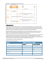
What is New in AOS-W Instant 6.3.1.1-4.0
The following features are added in the AOS-W Instant 6.3.1.1-4.0 release:
28 | About AOS-W Instant
AOS-W Instant 6.3.1.1-4.0 | User Guide
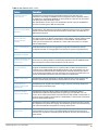
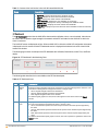
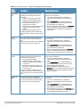
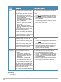
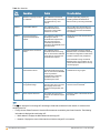
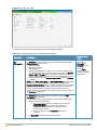
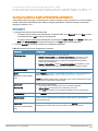
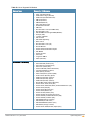
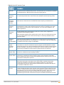
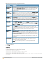
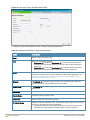
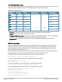
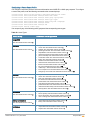
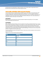
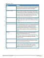
Table 3: New Features in 6.3.1.1-4.0
Feature
Description
Bandwidth contract
enhancements
AOS-W Instant supports assigning bandwidth contracts to the user roles. The
administrator can assign a bandwidth contract configured in Kbps to upstream (client to
the OAW-IAP) or downstream (OAW-IAP to clients) traffic for a user role. All users in that
role will be part of that bandwidth contract.
The administrators can also set per user bandwidth to provide a specific bandwidth for
each user connecting to the SSID or wired profile.
Support for 802.11r
Roaming and Fast BSS
Transition
AOS-W Instant supports 802.11r roaming standard. As part of the 802.11r
implementation, AOS-W Instant supports the Fast BSS Transition protocol. The Fast BSS
Transition mechanism minimizes the time required to resume data connectivity when a
BSS transition happens.
Support for Client
Roaming Based on
Opportunistic Key
Caching
AOS-W Instant also supports opportunistic key caching (OKC) based roaming. In the
OKC based roaming, the 802.1X authentication profile enables a cached pairwise master
key (PMK), which is used when a client roams to a new OAW-IAP. This allows faster
roaming of clients between the OAW-IAPs in a cluster, without the need for a complete
802.1X authentication.
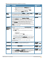
LACP on OAW-IAP220
Series
OAW-IAP220 Series supports link aggregation using either standard port-channel
(configuration based) or Link Aggregation Control Protocol (protocol signaling based).
OAW-IAP Guest
Management Interface
AOS-W Instant now supports a guest management interface for managing guest users.
OAW-IAP Integration with
Analytics and Location
Engine (ALE)
AOS-W Instant supports integration with Application and Location Engine (ALE). The ALE
server acts as a primary interface to all third-party applications and the OAW-IAP sends
client information and other status information to the ALE server.
OAW-IAP Integration with
Palo Alto Networks
Firewall
AOS-W Instant supports integration with the Palo Alto Networks (PAN) firewall. To
integrate an OAW-IAP with PAN user ID, a global profile is added. This profile can be
configured on an OAW-IAP with PAN firewall information such as IP address, port, user
name, password, firewall enabled or disabled status. OAW-IAP maintains the network
(such as mapping IP address) and user information for its clients in the network and can
provide the required information for the user ID feature on PAN firewall.
Domain-name based
ACL
AOS-W Instant supports configuration of domain-based Access Control List (ACL) rule.
Access to specific domains is allowed or denied based on the ACL rule definition.
Enhancements to
Internal Captive Portal
Splash Page
AOS-W Instant now supports customization of logo, policy text, and usage terms for the
internal Captive portal splash page.
Support for multiple
Captive portal profiles
AOS-W Instant supports multiple Captive portal profiles and allows the users to
customize the Captive portal profiles based on guest logon role and SSID. You can
create a set of captive portal profiles and associate them with an SSID or wired profile, or
create an external Captive portal profile for a WLAN SSID or a wired profile in the WLAN
wizard or Wired Network window.
Client Match
AOS-W Instant supports the ARM client match feature that continually monitors a client's
RF neighborhood to provide the ongoing client bandsteering service and load balancing,
and enhanced OAW-IAP reassignment for roaming mobile clients.
Support for Spanning
Tree Protocol
AOS-W Instant allows enabling of Spanning Tree Protocol (STP) on a wired profile. STP
ensures that there are no loops in any bridged Ethernet network and operates on all
downlink ports, regardless of forwarding mode. By default, Spanning Tree is disabled on
wired profiles.
AOS-W Instant 6.3.1.1-4.0 | User Guide
About AOS-W Instant | 29
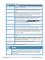
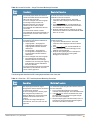
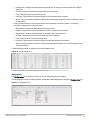
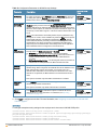
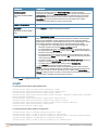
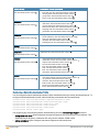
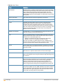
Table 3: New Features in 6.3.1.1-4.0
Feature
Description
Customizing Internal
Captive Portal Certificate
AOS-W Instant now supports uploading of customized internal Captive Portal server
certificates to the OAW-IAP database.
Provisioning an OAWIAP as a master OAWIAP
AOS-W Instant now allows you to manually provision an OAW-IAP as a master OAW-IAP,
based on network-specific parameters such as the physical location of the Virtual
Controller.
Support for Automatic
Configuration of the GRE
Tunnel
AOS-W Instant now allows the automatic configuration of GRE tunnel from an OAW-IAP
to Alcatel-Lucent OmniAccess WLAN Switch. By using an IPsec connection, the OAWIAPs can now set up a GRE tunnel with the switch. This feature eliminates the need for
the manual configuration of tunnel interface on the switch.
DHCP Relay Support
AOS-W Instant now supports the Centralized DHCP scope to serve the L3 clients. When
this feature is enabled, the OAW-IAP relays all DHCP request packets to the DHCP
server and acts as gateway for the centralized DHCP scope serving L3 clients.
OAW-IAP Provisioning
Enhancements
For option DHCP 43, besides the old format <organization>,<ams-ip>,<ams-key>, AOSW Instant now supports a new format <organization>,<ams-domain>. Also, the OAW-IAP
now performs a certificate-based authentication with OmniVista Management server,
instead of the current PSK-based login process.
Support for HTTP Proxy
Configuration
AOS-W Instant now supports HTTP proxy configuration. The HTTP proxy enables the
OAW-IAP to download the image from the cloud server.
AirGroup Enhancements
AOS-W Instant now supports different AirGroup services such as iTunes, Sharing, Chat,
and so on. You can either allow all services or customize the required services.
Dynamic RADIUS Proxy
(DRP) IP address
configuration
AOS-W Instant allows the configuration of separate IP address and VLAN details, which
can be used as source IP address and VLAN for RADIUS packets. When the dynamic
RADIUS proxy IP address and VLAN are configured, the clients associated with an OAWIAP can be authenticated with multiple RADIUS servers, across different geographical
areas, networks, and VLANs.
Restricted access
management
AOS-W Instant allows you to configure management subnets and restrict access to the
corporate network in order to prevent unauthorized users from accessing the corporate
network.
Uplink VLAN monitoring
and detection on
upstream devices
The AOS-W Instant UI now displays an alert message when a client connects to an SSID
or wired interface with a VLAN ID that is not allowed on the upstream device. The alert
message notifies the users about the mismatch in the VLAN configuration on the OAWIAP or the upstream device of an OAW-IAP.
Telnet access to the
AOS-W Instant CLI
AOS-W Instant now supports Telnet access to the AOS-W Instant CLI.
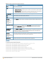
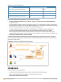
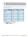
Table 4: New Hardware Platforms introduced in this release
OAW-IAP
Platform
OAWIAP224/225
30 | About AOS-W Instant
Description
The OAW-IAP224 and OAW-IAP225 wireless access points support the IEEE 802.11ac standard for
high-performance WLAN. These APs use MIMO (Multiple-in, Multiple-out) technology and other
high-throughput mode techniques to deliver high-performance, 802.11n 2.4 GHz and 802.11ac 5
GHz functionality while simultaneously supporting existing legacy wireless services. The OAWIAP220 Series support 802.11ac on the 5GHz band using 80 MHz channels. For more information
about this product, visit .
AOS-W Instant 6.3.1.1-4.0 | User Guide
OAW-IAP
Platform
OAWIAP114/115
Description
The OAW-IAP114 and OAW-IAP115 are dual radio, dual-band wireless access points that support
the IEEE 802.11n standard for high-performance WLAN. These APs use MIMO (Multiplein, Multipleout) technology and other high-throughput mode techniques to deliver high-performance, 802.11n
2.4 GHz and 5 GHz functionality while simultaneously supporting existing 802.11a/b/g wireless
services. For more information about this product, visit .
Check with your local Dell sales representative on device availability for your region.
AOS-W Instant 6.3.1.1-4.0 | User Guide
About AOS-W Instant | 31
Chapter 3
Setting up an OAW-IAP
This chapter describes the following procedures:
l
Setting up AOS-W Instant Network on page 32
l
Logging in to the AOS-W Instant UI on page 34
l
Accessing the AOS-W Instant CLI on page 35
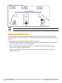
Setting up AOS-W Instant Network
Before installing an OAW-IAP:
l
Ensure that you have an Ethernet cable of the required length to connect an OAW-IAP to the home router.
l
Ensure that you have one of the following power sources:
n
IEEE 802.3af/at-compliant Power over Ethernet (PoE) source. The PoE source can be any power source
equipment (PSE) switch or a midspan PSE device.
n
OAW-IAP power adapter kit.
Perform the following procedures to set up the AOS-W Instant network:
1. Connecting an OAW-IAP on page 32
2. Assigning an IP address to the OAW-IAP on page 32
3. Connecting to a Provisioning Wi-Fi Network on page 33
Connecting an OAW-IAP
Based on the type of the power source used, perform one of the following steps to connect an OAW-IAP to the power
source:
l
PoE switch— Connect the ENET 0 port of the OAW-IAP to the appropriate port on the PoE switch.
l
PoE midspan— Connect the ENET 0 port of the OAW-IAP to the appropriate port on the PoE midspan.
l
AC to DC power adapter— Connect the 12V DC power jack socket to the AC to DC power adapter.
OAW-RAP155P supports PSE for 802.3at powered device (class 0-4) on one port (E1 or E2), or 802.3af powered
DC IN (Power Socket) on two ports (E1 and E2).
Assigning an IP address to the OAW-IAP
The OAW-IAP needs an IP address for network connectivity. When you connect an OAW-IAP to a network, it
receives an IP address from a DHCP server.
To obtain an IP address for an OAW-IAP:
1. Ensure that the DHCP service is enabled on the network.
2. Connect the ENET 0 port of OAW-IAP to a switch or router using an Ethernet cable.
3. Connect the OAW-IAP to a power source. The OAW-IAP receives an IP address provided by the switch or
router.
If there is no DHCP service on the network, the OAW-IAP can be assigned a static IP address. If a static IP is not
assigned, the OAW-IAP obtains an IP automatically within the 169.254 subnet.
AOS-W Instant 6.3.1.1-4.0 | User Guide
Setting up an OAW-IAP | 32
Assigning a Static IP
To assign a static IP to an OAW-IAP:
1. Connect a terminal, PC, or workstation running a terminal emulation program to the Console port on the OAWIAP.
2. Power on the OAW-IAP. An autoboot countdown prompt that allows you to interrupt the normal startup process
and access apboot is displayed.
3. Click Enter before the timer expires. The OAW-IAP goes into the apboot mode.
4. In the apboot mode, use the following commands to assign a static IP to the OAW-IAP.
Hit <Enter> to stop autoboot: 0
apboot>
apboot> setenv ipaddr 192.0.2.0
apboot> setenv netmask 255.255.255.0
apboot> setenv gatewayip 192.0.2.2
apboot> save
Saving Environment to Flash...
Un-Protected 1 sectors
.done
Erased 1 sectors
Writing
5. Use the printenv command to view the configuration.
apboot> printenv
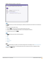
Connecting to a Provisioning Wi-Fi Network
The OAW-IAPs boot with factory default configuration and try to provision automatically. If the automatic
provisioning is successful, the instant SSID will not be available. If OmniVista and Activate are not reachable and
the automatic provisioning fails, the instant SSID becomes available and the users can connect to a provisioning
network by using the instant SSID.
To connect to a provisioning Wi-Fi network:
1. Ensure that the client is not connected to any wired network.
2. Connect a wireless enabled client to a provisioning Wi-Fi network: for example, instant.
3. If the Windows OS system is used:
a. Click the wireless network connection icon in the system tray. The Wireless Network Connection window
is displayed.
b. Click on the instant network and then click Connect.
4. If the Mac OS system is used:
a. Click the AirPort icon. A list of available Wi-Fi networks is displayed.
b. Click on the instant network.
The instant SSIDs are broadcast in 2.4 GHz only.
OAW-IAP Cluster
OAW-IAPs in the same VLAN automatically find each other and form a single functioning network managed by a
Virtual Controller.
Moving an OAW-IAP from one cluster to another requires a factory reset of the OAW-IAP.
33 | Setting up an OAW-IAP
AOS-W Instant 6.3.1.1-4.0 | User Guide
Disabling the Provisioning Wi-Fi Network
The provisioning network is enabled by default. AOS-W Instant provides the option to disable the provisioning
network through the console port. Use this option only when you do not want the default SSID instant to be
broadcast in your network.
To disable the provisioning network:
1. Connect a terminal or PC/workstation running a terminal emulation program to the Console port on the OAWIAP.
2. Configure the terminal or terminal emulation program to use the following communication settings:
Table 5: Terminal Communication Settings
Baud Rate
Data Bits
Parity
Stop Bits
Flow Control
9600
8
None
1
None
3. Power on the OAW-IAP. An autoboot countdown prompt that allows you to interrupt the normal startup process
and access apboot is displayed.
4. Click Enter before the timer expires. The OAW-IAP goes into the apboot mode through console.
5. In the apboot mode, use the following commands to disable the provisioning network:
n
apboot> factory_reset
n
apboot> setenv disable_prov_ssid 1
n
apboot> saveenv
n
apboot> reset
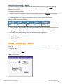
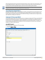
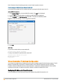
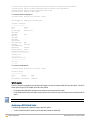
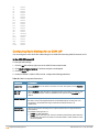
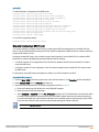
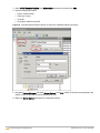
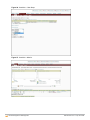
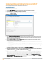
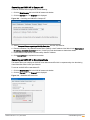
Logging in to the AOS-W Instant UI
Launch a web browser and enter http://instant.Alcatel-Lucentnetworks.com. In the login screen, enter the following
credentials:
l
Username— admin
l
Password— admin
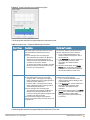
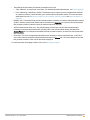
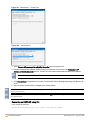
The following figure shows the Login screen:
Figure 1 Login Screen
AOS-W Instant 6.3.1.1-4.0 | User Guide
Setting up an OAW-IAP | 34
When you use a provisioning Wi-Fi network to connect to the Internet, all browser requests are directed to the AOSW Instant UI. For example, if you enter www.example.com in the address field, you are directed to the AOS-W
Instant UI. You can change the default login credentials after the first login.
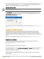
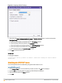
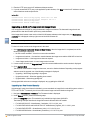
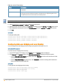
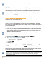
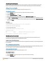
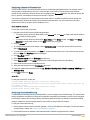
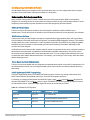
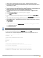
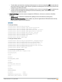
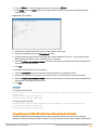
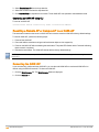
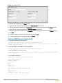
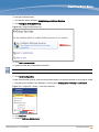
Specifying Country Code
This procedure is applicable to the OAW-IAP-ROW (Rest of World) variants only. Skip this step if you are installing
OAW-IAP in the United States, Japan, or Israel.
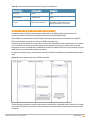
The Country Code window is displayed for the OAW-IAP-ROW (Rest of World) variants when you log in to the
AOS-W Instant UI for the first time. You can specify a country code by selecting an appropriate option from the
Please Specify the Country Code drop-down list.
Figure 2 Specifying a Country Code
.
For the complete list of the country codes supported by the OAW-IAP-ROW variant type, see Regulatory Domain on
page 322.
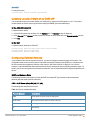
Accessing the AOS-W Instant CLI
AOS-W Instant supports the use of Command Line Interface (CLI) for scripting purposes. When you make
configuration changes on a master OAW-IAP in the CLI, all associated OAW-IAPs in the cluster inherit these
changes and subsequently update their configurations. By default, you can access the CLI from the serial port or
from an SSH session. You must explicitly enable Telnet access on the OAW-IAP to access the CLI through a Telnet
session.
For information on enabling SSH and Telnet access to the OAW-IAP CLI, see Enabling Terminal Access on page
73.
Connecting to a CLI Session
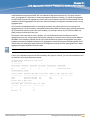
On connecting to a CLI session, the system displays its host name followed by the login prompt. Use the
administrator credentials to start a CLI session. For example:
(Instant Access Point)
User: admin
ode is enabled and a command prompt is displayed. For example:
(Instant Access Point)#
The privileged mode provides access to show, clear, ping, traceroute, and commit commands. The configuration
commands are available in config mode. To move from privileged mode to the configuration mode, enter the
following command at the command prompt:
(Instant Access Point)# configure terminal
The configure terminal command allows you to enter the basic configuration mode and the command prompt is
displayed as follows:
(Instant Access Point)(config)#
35 | Setting up an OAW-IAP
AOS-W Instant 6.3.1.1-4.0 | User Guide
The AOS-W Instant CLI allows CLI scripting in several other sub-command modes to allow the users to configure
individual interfaces, SSIDs, access rules, and security settings.
You can use the question mark (?) to view the commands available in a privileged mode, configuration mode, or submode.
Although automatic completion is supported for some commands such as configure terminal, the complete exit
and end commands must be entered at command prompt.
Applying Configuration Changes
Each command processed by the Virtual Controller is applied on all the slaves in a cluster. The changes configured
in a CLI session are saved in the CLI context. The CLI does not support the configuration data exceeding the 4K
buffer size in a CLI session. Therefore, Alcatel-Lucent recommends that you configure fewer changes at a time and
apply the changes at regular intervals.
To apply and save the configuration changes at regular intervals, use the following command in the privileged mode:
(Instant Access Point)# commit apply
To apply the configuration changes to the cluster without saving the configuration, use the following command in the
privileged mode:
(Instant Access Point)# commit apply no-save
To view the changes that are yet to be applied, use the following command in the privileged mode:
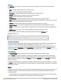
(Instant Access Point)# show uncommitted-config
To revert to the earlier configuration, use the following command in the privileged mode.
(Instant Access Point)# commit revert
Example:
(Instant
(Instant
(Instant
(Instant
(Instant
(Instant
(Instant
(Instant
Access
Access
Access
Access
Access
Access
Access
Access
Point)(config)# rf dot11a-radio-profile
Point)(RF dot11a Radio Profile)# beacon-interval 200
Point)(RF dot11a Radio Profile)# no legacy-mode
Point)(RF dot11a Radio Profile)# dot11h
Point)(RF dot11a Radio Profile)# interference-immunity 3
Point)(RF dot11a Radio Profile)# csa-count 2
Point)(RF dot11a Radio Profile)# spectrum-monitor
Point)(RF dot11a Radio Profile)# end
(Instant Access Point)# show uncommitted-config
rf dot11a-radio-profile
no legacy-mode
beacon-interval 200
no dot11h
interference-immunity 3
csa-count 1
no spectrum-monitor
Instant Access Point# commit apply
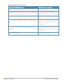
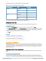
Using Sequence Sensitive Commands
The AOS-W Instant CLI does not support positioning or precedence of sequence-sensitive commands. Therefore,
Alcatel-Lucent recommends that you remove the existing configuration before adding or modifying the configuration
details for sequence-sensitive commands. You can either delete an existing profile or remove a specific
configuration by using the no… commands.
The following table lists the sequence-sensitive commands and the corresponding no command to remove the
configuration.
AOS-W Instant 6.3.1.1-4.0 | User Guide
Setting up an OAW-IAP | 36
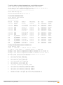
Table 6: Sequence-Sensitive Commands
Sequence-Sensitive Command
Corresponding no command
opendns <username <password>
no opendns
rule <dest> <mask> <match> <protocol> <start-port> <e
nd-port> {permit |deny | src-nat | dst-nat {<IP-addre
ss> <port>| <port>}}[<option1....option9>]
no rule <dest> <:mask> <match> <prot
ocol> <start-port> <end-port> {permi
t | deny | src-nat | dst-nat}
mgmt-auth-server <auth-profile-name>
no mgmt-auth-server <auth-profile-na
me>
set-role <attribute>{{equals| not-equals| startswith| ends-with| contains} <operator> <role>| valueof}
no set-role <attribute>{{equals|
not-equals| starts-with| ends-with|
contains} <operator>| value-of}
no set-role
set-vlan <attribute>{{equals| not-equals| startswith| ends-with| contains} <operator> <VLAN-ID>|
value-of}
no set-vlan <attribute>{{equals|
not-equals| starts-with| ends-with|
contains} <operator>| value-of}
no set-vlan
auth-server <name>
37 | Setting up an OAW-IAP
no auth-server <name>
AOS-W Instant 6.3.1.1-4.0 | User Guide
Chapter 4
AOS-W Instant User Interface
This chapter describes the following AOS-W Instant UI elements:
l
Login Screen
l
Main Window
Login Screen
The AOS-W Instant login page allows you to:
l
Log in to the AOS-W Instant UI.
l
View AOS-W Instant Network Connectivity summary
l
View the AOS-W InstantUI in a specific language
Logging into the AOS-W Instant UI
To log in to the AOS-W Instant UI, enter the following credentials:
l
Username— admin
l
Password— admin
The AOS-W Instant UI main window is displayed.
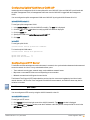
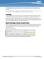
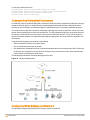
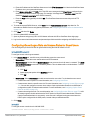
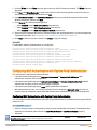
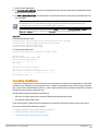
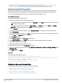
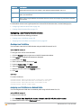
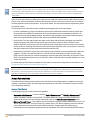
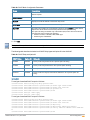
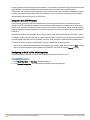
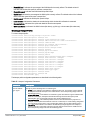
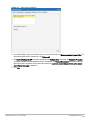
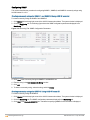
Viewing Connectivity Summary
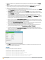
The Login page also displays the connectivity status to the AOS-W Instant network. The users can view a summary
that indicates the status of the Internet availability, uplink, cellular modem and signal strength, VPN, and OmniVista
configuration details before logging in to the AOS-W Instant UI.
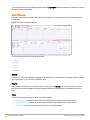
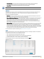
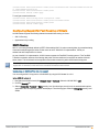
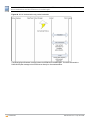
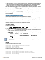
The following figure shows the information displayed in the connectivity summary:
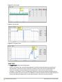
Figure 3 Connectivity Summary
The Internet status is available only if the Internet failover feature (System>Show advanced
option>uplink>Internet failover) is enabled.
The cellular provider and cellular strength information is only available when a 3G or 4G modem is in use.
Language
The Language drop-down lists the languages and allow users to select their preferred language before logging in to
the AOS-W Instant UI. A default language is selected based on the language preferences in the client desktop
operating system or browser. If AOS-W Instant cannot detect the language, then English is used as the default
language.
AOS-W Instant 6.3.1.1-4.0 | User Guide
AOS-W Instant User Interface | 38
You can also select the required language option from the Languages drop-down located at the bottom left corner of
the AOS-W Instant main window.
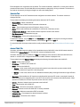
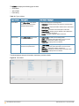
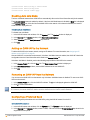
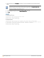
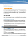
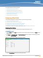
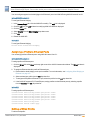
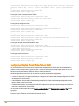
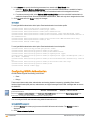
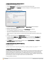
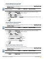
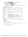
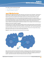
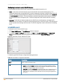
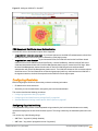
Main Window
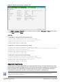
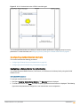
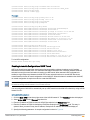
On logging into Instant, the Instant UI Main Window is displayed. The following figure shows the AOS-W Instant
main window:
Figure 4 AOS-W Instant Main Window
The main window consists of the following elements:
l
Banner
l
Search
l
Tabs
l
Links
l
Views
Banner
The banner is a horizontal rectangle that appears at the top left corner of the AOS-W Instant main window. It displays
the company name, logo, and Virtual Controller's name.
Search
Administrators can search for an OAW-IAP, client, or a network in the Search text box. When you type a search
text, the search function suggests matching keywords and allows you to automatically complete the search text
entry.
Tabs
The AOS-W Instant main window consists of the following tabs:
n
Networks Tab— Provides information about the network profiles configured in the Instant network.
n
Access Points Tab— Provides information about the OAW-IAPs configured in the Instant network.
n
Clients Tab— Provides information about the clients in the Instant network.
39 | AOS-W Instant User Interface
AOS-W Instant 6.3.1.1-4.0 | User Guide
Each tab appears in a compressed view by default. The number of networks, OAW-IAPs, or clients in the network
precedes the tab names. The individual tabs can be expanded or collapsed by clicking on the tabs. The list items in
each tab can be sorted by clicking the triangle icon next to the heading labels.
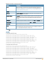
Networks Tab
This tab displays a list of Wi-Fi networks that are configured in the Instant network. The network names are
displayed as links.
The expanded view displays the following information about each Wi-Fi network:
l
Name (SSID) — Name of the network.
l
Clients — Number of clients that are connected to the network.
l
Type — Type of network type such as Employee, Guest, or Voice.
l
Band — Band in which the network is broadcast: 2.4 GHz band, 5 GHz band, or both.
l
Authentication Method — Authentication method required to connect to the network.
l
Key Management — Authentication key type.
l
IP Assignment— Source of IP address for the client.
To add a Wi-Fi network, click the New link in the Networks tab. An edit link is displayed on clicking the network
name in the Networks tab. To delete a network, click on the link x next to the edit link.
For more information on the procedure to add or modify a wireless network, see Wireless Network Profiles on page
85.
Access Points Tab
If the Auto Join Mode feature is enabled, a list of enabled and active OAW-IAPs in the AOS-W Instant network is
displayed in the Access Points tab. The OAW-IAP names are displayed as links.
If the Auto Join Mode feature is disabled, the New link is displayed. Click this link to add a new OAW-IAP to the
network. If an OAW-IAP is configured and not active, its MAC Address is displayed in red.
The expanded view of the Access Points tab displays the following information about each OAW-IAP:
l
Name — Name of the OAW-IAP.
l
IP Address — IP address of the OAW-IAP.
l
Mode — Mode of the OAW-IAP.
n
Access — In this mode, the AP serves clients and scans the home channel for spectrum analysis while
monitoring channels for rogue APs in the background.
n
Monitor — In this mode, the AP acts as a dedicated Air Monitor (AM), scanning all channels for rogue APs and
clients.
l
Spectrum— When enabled, the AP functions as a dedicated full-spectrum RF monitor, scanning all channels to
detect interference from neighboring APs or non-Wi-Fi devices such as microwaves and cordless phones. When
Spectrum is enabled, the AP does not provide access services to clients.
l
Clients — Number of clients that are connected to the OAW-IAP.
l
Type — Model number of the OAW-IAP.
l
Mesh Role — Role of the mesh portal or mesh point.
l
Channel — Channel on which the OAW-IAP is currently broadcast.
l
Power (dB) — Maximum transmission EIRP of the radio.
l
Utilization (%) — Percentage of time that the channel is utilized. l
Noise (dBm) — Noise floor of the channel.
AOS-W Instant 6.3.1.1-4.0 | User Guide
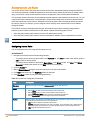
AOS-W Instant User Interface | 40
An edit link is displayed on clicking the OAW-IAP name. For details about editing OAW-IAP settings see Initial
Configuration Tasks on page 67.
Clients Tab
This tab displays a list of clients that are connected to the AOS-W Instant network. The client names are displayed
as links. The expanded view displays the following information about each client:
l
Name — User name of the client or guest users if available.
l
IP Address — IP address of the client.
l
MAC Address — MAC address of the client.
l
OS — Operating system that runs on the client.
l
Network — The network to which the client is connected.
l
Access Point — OAW-IAP to which the client is connected.
l
Channel — The client operating channel.
l
Type — Type of the Wi-Fi client: A, G, AN, or GN.
l
Role — Role assigned to the client.
l
Signal — Current signal strength of the client, as detected by the AP.
l
Speed (mbps) — Current speed at which data is transmitted. When the client is associated with an AP, it
constantly negotiates the speed of data transfer. A value of 0 means that the AP has not heard from the client for
some time.
Links
The following links allow you to configure various features for the AOS-W Instant network:
n
New Version Available
n
System
n
RF
n
Security
n
Maintenance
n
More
n
Help
n
Logout
n
Monitoring
n
Spectrum
n
Alerts
n
IDS
n
Configuration
n
AirGroup
n
OmniVista Setup
n
Pause/Resume
Each of these links is explained in the subsequent sections.
New Version Available
This link is displayed in the top right corner of AOS-W Instant main window only if a new image version is available
on the image server and OmniVista is not configured. For more information about the New version available link
and its functions, see Upgrading an OAW-IAP on page 70.
41 | AOS-W Instant User Interface
AOS-W Instant 6.3.1.1-4.0 | User Guide
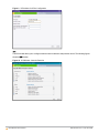
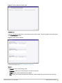
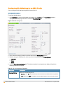
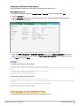
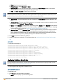
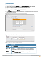
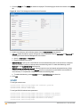
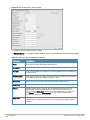
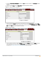
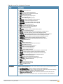
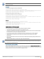
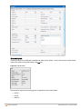
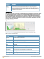
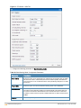
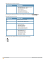
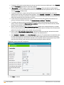
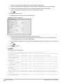
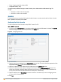
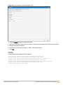
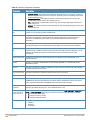
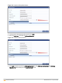
System
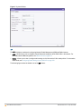
This link displays the System window. The System window consists of the following tabs:
Use the Show/Hide Advanced option at the bottom of the System window to view or hide the advanced options.
l
General— Allows you to configure, view or edit the Name, IP address, NTP Server, and other OAW-IAP settings
for the Virtual Controller.
n
For information about Virtual Controller configuration, see Virtual Controller Configuration on page 82.
n
For information about NTP Server configuration, see Configuring an NTP Server on page 77.
n
For information about Auto join mode, Terminal Access, LED display, TFTP Dump Server, and Deny inter
user bridging, see OAW-IAP Management on page 304.
l
Admin — Allows you to configure administrator credentials for access to the Virtual Controller Management User
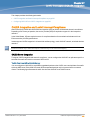
Interface. You can also configure OmniVista in this tab. For more information on management interface and
OmniVista configuration, see Configuring Authentication Parameters for Virtual Controller Management Interface
on page 150 and Configuring Omnivista on page 260 respectively.
l
DHCP—Allows you to configure DHCP server settings for the Virtual Controller.
l
Uplink — Allows you to view or configure uplink settings. See Uplink Configuration on page 187 for more
information.
l
L3 Mobility — Allows you to view or configure the Layer-3 mobility settings. See Configuring L3-Mobility on page
201 for more information.
l
Enterprise Domains — Allows you to view or configure the DNS domain names that are valid in the enterprise
network. See Configuring Enterprise Domains on page 229 for more information.
l
Monitoring — Allows you to view or configure the following details:
n
Syslog — Allows you to view or configure Syslog Server details for sending syslog messages to the external
servers. See Configuring a Syslog Server on page 314 for more information.
n
TFTP Dump — Allows you to view or configure a TFTP dump server for core dump files. See Configuring
TFTP Dump Server on page 316 for more information.
n
SNMP — Allows you to view or configure SNMP agent settings. See Configuring SNMP on page 311 for more
information.
l
WISPr — Allows you to view or configure the WISPr settings. See Configuring WISPr Authentication on page 157
for more information.
l
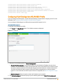
Proxy — Allows you to configure HTTP proxy on an OAW-IAP. See Configuring HTTP Proxy on an OAW-IAP on
page 71 for more information.
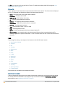
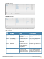
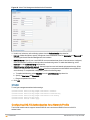
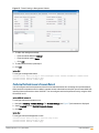
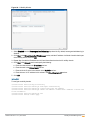
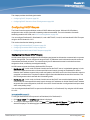
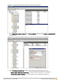
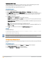
The following figure shows the default view of the System window.
AOS-W Instant 6.3.1.1-4.0 | User Guide
AOS-W Instant User Interface | 42
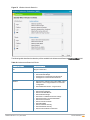
Figure 5 System Window
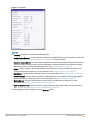
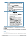
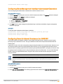
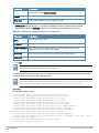
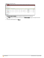
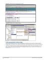
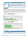
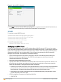
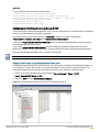
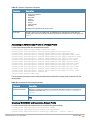
RF
The RF link displays a window for configuring Adaptive Radio Management (ARM) and Radio features.
l
ARM — Allows you to view or configure channel and power settings for all the OAW-IAPs in the network. For
information about ARM configuration, see ARM Overview on page 211.
l
Radio — Allows you to view or configure radio settings for 2.4 GHz and the 5 GHz radio profiles. For information
about Radio, see Configuring Radio Settings for an OAW-IAP on page 218.
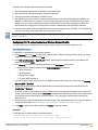
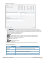
The following figure shows the default view of the RF window:
43 | AOS-W Instant User Interface
AOS-W Instant 6.3.1.1-4.0 | User Guide
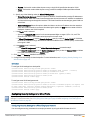
Figure 6 RF Window
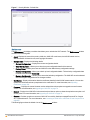
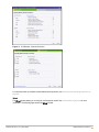
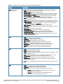
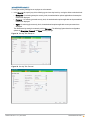
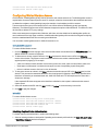
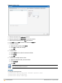
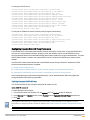
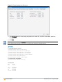
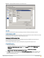
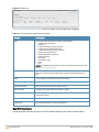
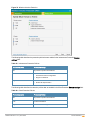
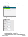
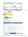
Security
The Security link displays a window with the following tabs:
l
Authentication Servers— Use this window to configure an external RADIUS server for a wireless network. See
Configuring an External Server for Authentication on page 144 for more information.
l
Users for Internal Server— Use this window to populate the system’s internal authentication server with users.
This list is used by networks for which per-user authorization is specified using the Virtual Controller’s internal
authentication server. For more information about users, see User Management on page 128.
l
Roles— Use this window to view the roles defined for all the Networks. The Access Rules part allows you to
configure permissions for each role. For more information, see Configuring User Roles on page 175.
l
Blacklisting— Use this window to blacklist clients. For more information, see Blacklisting Clients on page 158.
l
Firewall Settings— Use this window to enable or disable Application Layer Gateway (ALG) supporting address
and port translation for various protocols. For more information, see Roles and Policies on page 164.
l
Walled Garden—Use this window to allow or prevent access to a selected list of Websites. For more
information, see Configuring Walled Garden Access on page 126.
l
External Captive Portal— Use this window to configure external Captive portal profiles. For more information,
see Configuring External Captive Portal for a Guest Network on page 118.
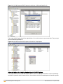
The following figure shows the default view of the Security window:
AOS-W Instant 6.3.1.1-4.0 | User Guide
AOS-W Instant User Interface | 44
Figure 7 Security Window - Default View
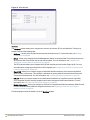
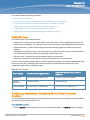
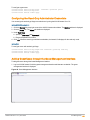
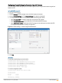
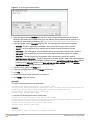
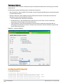
Maintenance
The Maintenance link displays a window that allows you to maintain the Wi-Fi network. The Maintenance window
consists of the following tabs:
l
About—Displays the name of the product, build time, OAW-IAP model name, the AOS-W Instant version,
Website address of Alcatel-Lucent, and Copyright information.
l
Configuration— Displays the following details:
n
Current Configuration — Displays the current configuration details.
n
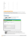
Clear Configuration —Allows you to clear the current configuration details of the network.
n
Factory Reset —Allows you to reset an OAW-IAP to the default factory configuration settings.
n
Backup Configuration — Allows you to back up local configuration details. The backed up configuration data
is saved in the file named instant.cfg.
n
Restore Configuration — Allows you to restore the backed up configuration. The OAW-IAP must be rebooted
after restoring the configuration for the changes to affect.
l
Certificates — Displays information about the certificates installed in the AOS-W Instant network. You can also
upload new certificates and set a passphrase for the certificates. For more information, see Uploading
Certificates on page 160.
l
Firmware — Displays the current firmware version and provides various options to upgrade to a new firmware
version. For more information, see Upgrading an OAW-IAP on page 70.
l
Reboot — Displays the OAW-IAPs in the network and provides an option to reboot the required access point or all
access points. For more information, see Upgrading an OAW-IAP on page 70.
l
Convert — Provides an option to convert an OAW-IAP to a mobility Switches managed Remote AP or Campus
AP, or a standalone AP. For more information, see Converting an OAW-IAP to a Remote AP and Campus AP on
page 305.
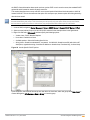
The following figure shows the default view of the Maintenance window:
45 | AOS-W Instant User Interface
AOS-W Instant 6.3.1.1-4.0 | User Guide
Figure 8 Maintenance Window - Default View
Help
The Help link allows you to view a short description or definition of selected terms and fields in the UI windows or
dialogs.
To activate the context-sensitive help:
1. Click the Help link at the top right corner of AOS-W Instant main window.
2. Click any text or term displayed in green italics to view its description or definition.
3. To disable the help mode, click Done.
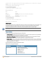
More
The More link allows you to select the following options:
l
VPN
l
IDS
l
Wired
l
Services
l
DHCP Server
l
Support
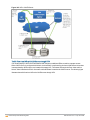
VPN
The VPN window allows you to define communication settings with a remote Switch. See VPN Configuration on
page 239 for more information. The following figure shows the an example of the IPSec configuration options
available in the VPN window:
AOS-W Instant 6.3.1.1-4.0 | User Guide
AOS-W Instant User Interface | 46
Figure 9 VPN window for IPSec Configuration
IDS
The IDS window allows you to configure wireless intrusion detection and protection levels. The following figures
show the IDS window:
Figure 10 IDS Window: Intrusion Detection
47 | AOS-W Instant User Interface
AOS-W Instant 6.3.1.1-4.0 | User Guide
Figure 11 IDS Window: Intrusion Protection
For more information on wireless intrusion detection and protection, see Detecting and Classifying Rogue APs on
page 221.
Wired
The Wired window allows you to configure a wired network profile. See Wired Profiles on page 102 for more
information. The following figure shows the Wired window:
AOS-W Instant 6.3.1.1-4.0 | User Guide
AOS-W Instant User Interface | 48
Figure 12 Wired Window
Services
The Services window allows you to configure services such as AirGroup, RTLS, and OpenDNS. The Services
window consists of the following tabs:
l
AirGroup — Allows you to configure the AirGroup and AirGroup services. For more information, see AirGroup
Configuration on page 268.
l
RTLS — Allows you to integrate OmniVista Management platform or third-party Real Time Location Server such
as Aeroscout Real Time Location Server with AOS-W Instant. For more information, see Integration with
Security and Location Services Applications on page 276.
The RTLS tab also allows you to integrate OAW-IAP with the Analytics and Location Engine (ALE). For more
information about configuring an OAW-IAP for ALE integration, see Configuring an OAW-IAP for Analytics and
Location Engine Support on page 276.
l
OpenDNS— Allows you to configure support for OpenDNS business solutions, which require an OpenDNS
(www.opendns.com) account. The OpenDNS credentials are used by AOS-W Instant and OmniVista to filter
content at the enterprise level. For more information, see Configuring OpenDNS Credentials on page 229.
l
CALEA—Allows you configure support for Communications Assistance for Law Enforcement Act (CALEA)
server integration, thereby ensuring compliance with Lawful Intercept and CALEA specifications. For more
information, see Lawful Intercept and CALEA Integration on page 281
l
Network Integration—Allows you configure an OAW-IAP for integration with Palo Alto Networks (PAN) Firewall.
For more information about OAW-IAP integration with PAN, see Integrating an OAW-IAP with Palo Alto
Networks Firewall on page 278.
The following figure shows the default view of the Services window:
49 | AOS-W Instant User Interface
AOS-W Instant 6.3.1.1-4.0 | User Guide
Figure 13 Services Window: Default View
DHCP Server
The DHCP Servers window allows you to configure various DHCP modes. The following figure shows the contents
of the DHCP Servers window:
Figure 14 DHCP Servers Window
For more information, see DHCP Configuration on page 231.
Support
The Support consists of the following fields:
l
Command— Allows you to select a support command for execution.
l
Target—Displays a list of OAW-IAPs in the network.
l
Run— Allows you to execute the selected command for a specific OAW-IAP or all OAW-IAPs and view logs.
AOS-W Instant 6.3.1.1-4.0 | User Guide
AOS-W Instant User Interface | 50
l
Auto Run— Allows you to configure a schedule for automatic execution of a support command for a specific
OAW-IAP or all OAW-IAPs.
l
Filter—Allows you to filter the contents of a command output.
l
Clear—Clears the command output displayed after a command is executed.
l
Save Results— Allows you to save the support command logs as an HTML or text file.
For more information on support commands, see Running Debug Commands from the AOS-W Instant UI on page
317. The following figure shows the Support window:
Figure 15 Support Window
Logout
The Logout link allows you to log out of the AOS-W Instant UI.
Monitoring
The Monitoring link displays the Monitoring pane for the AOS-W Instant network. Use the down arrow
to the right side of these links to compress or expand the monitoring pane.
located
The monitoring pane consists of the following sections:
l
Info
l
RF Dashboard
l
RF Trends
l
Usage Trends
l
Mobility Trail
Info
The Info section displays the configuration information of the Virtual Controller by default. On selecting the Network
View tab, the monitoring pane displays configuration information of the selected network. Similarly in the Access
Point or the Client view, this section displays the configuration information of the selected OAW-IAP or the client.
51 | AOS-W Instant User Interface
AOS-W Instant 6.3.1.1-4.0 | User Guide
Table 7: Contents of the Info Section in the AOS-W Instant Main Window
Name
Description
Info section in Virtual
Controller view
l
Info section in Client view
The Info section in the Virtual Controller view displays the following information:
Name— Displays the Virtual Controller name.
l System Location—Displays the system location.
l Country Code— Displays the Country in which the Virtual Controller is operating.
l Virtual Controller IP address— Displays the IP address of the Virtual Controller.
l OmniVista Server and Backup Server — Displays the names of the OmniVista
server and the backup servers if OmniVista servers are configured.
l Band— Displays the band in which the Virtual Controller is operating — 2.4 GHz
band, 5 GHz band, or both.
l Master— Displays the IP address of the Access Point acting as Virtual Controller.
l OpenDNS Status— Displays the OpenDNS status. If the OpenDNS status indicates
as Not Connected, ensure that the network connection is up and appropriate
credentials are configured for OpenDNS.
l MAS integration— Displays the status of the MAS integration feature.
l Uplink type — Displays the type of uplink configured on the OAW-IAP: for example,
Ethernet or 3G.
l Uplink status — Indicates the uplink status.
l Blacklisted clients — Displays the number of blacklisted clients.
l Internal RADIUS Users — Displays the number of internal RADIUS users.
l Internal Guest Users — Displays the number of internal guest users.
l Internal User Open Slots— Displays the available slots for user configuration as
supported by the OAW-IAP model.
The Info section in the Client view displays the following information:
Name— Displays the name of the client.
l IP Address— Displays IP address of the client.
l MAC Address— Displays MAC Address of the client.
l OS— Displays the Operating System that is running on the client.
l Network— Indicates the network to which the client is connected.
l Access Point— Indicates the OAW-IAP to which the client is connected.
l Channel— Indicates the channel that is currently used by the client.
l Type— Displays the channel type on which client is broadcasting.
l
Info section in Network view
The Info section in the Network view displays the following information:
Name — Displays Name of the network.
l Status — Displays the status of network.
l Band — Displays the band in which the network is broadcast: For example, 2.4 GHz
band, 5 GHz band, or both.
l Type — Displays the type of network: For example, Employee, Guest, or Voice.
l IP Assignment— Displays the source of IP address for the client.
l Access— Indicates the level of access control configured for the network.
l Security level— Indicates the type of user authentication and data encryption
configured for the network
l
The info section for WLAN SSIDs also indicates status of Captive Portal and CALEA
ACLs.
Info section in Access Point
view
The Info section in the Access Point view displays the following information :
Name — Displays the name of the selected OAW-IAP.
l IP Address — Displays the IP address of the OAW-IAP.
l Mode — Displays the mode in which the AP is configured to operate:
l
l
l
AOS-W Instant 6.3.1.1-4.0 | User Guide
In Access mode, the OAW-IAP serves clients, while also monitoring
for rogue APs in the background.
In Monitor mode, the OAW-IAP acts as a dedicated monitor,
scanning all channels for rogue APs and clients.
AOS-W Instant User Interface | 52
Table 7: Contents of the Info Section in the AOS-W Instant Main Window
Name
Description
l
l
l
l
l
l
l
Spectrum — Displays the status of the spectrum monitor.
Clients — Number of clients associated with the OAW-IAP.
Type — Displays the model number of the OAW-IAP.
CPU Utilization — Displays the CPU utilization in percentage.
Memory Free — Displays the memory availability of the OAW-IAP in MB.
Serial number — Displays the serial number of the OAW-IAP.
From Port— Displays the port from where the slave OAW-IAP is learned in hierarchy
mode.
RF Dashboard
The RF Dashboard section lists the OAW-IAPs that exceed the utilization, noise, or error threshold. It also shows
the clients with low speed or signal strength in the network and the RF information for the OAW-IAP to which the
client is connected.
The OAW-IAP names are displayed as links. When an OAW-IAP is clicked, the OAW-IAP configuration information
is displayed in the Info section and the RF Dashboard section is displayed at the bottom left corner of the AOS-W
Instant main window.
The following figure shows an example of the RF dashboard with Utilization, Band frames, Noise Floor, and Errors
details:
Figure 16 RF Dashboard in the Monitoring Pane
The following table describes the icons available on the RF Dashboard pane:
Table 8: RF Dashboard Icons
Icon
Name
Description
1
Signal
Icon
Displays the signal strength of the client. Depending on the signal strength of the client, the color
of the lines on the Signal bar changes from Green > Orange > Red.
l Green— Signal strength is more than 20 decibels.
l Orange— Signal strength is between 15-20 decibels.
l Red— Signal strength is less than 15 decibels.
To view the signal graph for a client, click on the signal icon next to the client in the Signal
column.
2
Speed
icon
Displays the data transfer speed of the client. Depending on the data transfer speed of the client,
the color of the Signal bar changes from Green > Orange > Red.
l Green— Data transfer speed is more than 50 percent of the maximum speed supported by
the client.
l Orange— Data transfer speed is between 25-50 percent of the maximum speed supported by
the client.
l Red— Data transfer speed is less than 25 percent of the maximum speed supported by the
client.
To view the data transfer speed graph of a client, click on the speed icon against the client in the
Speed column.
53 | AOS-W Instant User Interface
AOS-W Instant 6.3.1.1-4.0 | User Guide
Icon
Name
Description
3
Utilization
icon
Displays the radio utilization rate of the OAW-IAPs. Depending on the percentage of utilization,
the color of the lines on the Utilization icon changes from Green > Orange > Red.
l Green— Utilization is less than 50 percent.
l Orange— Utilization is between 50-75 percent.
l Red— Utilization is more than 75 percent.
To view the utilization graph of an OAW-IAP, click the Utilization icon next to the OAW-IAP in the
Utilization column.
4
Noise icon
Displays the noise floor details for the OAW-IAPs. Noise is measured in decibels/meter.
Depending on the noise floor, the color of the lines on the Noise icon changes from Green >
Orange > Red.
l Green— Noise floor is more than 87 dBm.
l Orange— Noise floor is between 80 dBm-87 dBm.
l Red— Noise floor is less than 80 dBm.
To view the noise floor graph of an OAW-IAP, click the noise icon next to the OAW-IAP in the
Noise column.
5
Errors
icon
Displays the errors for the OAW-IAPs. Depending on the errors, color of the lines on the Errors
icon changes from Green > Yellow > Red.
l Green— Errors are less than 5000 frames per second.
l Orange— Errors are between 5000-10000 frames per second.
l Red— Errors are more than 10000 frames per second.
To view the errors graph of an OAW-IAP, click the Errors icon next to the OAW-IAP in the Errors
column.
RF Trends
The RF Trends section displays the following graphs for the selected client:
Figure 17 Signal Graph
AOS-W Instant 6.3.1.1-4.0 | User Guide
AOS-W Instant User Interface | 54
Figure 18 Frames Graph
Figure 19 Speed Graph
Figure 20 Throughput Graph
Usage Trends
The Usage Trends displays the following graphs:
l
Clients — In the default view, the Clients graph displays the number of clients that were associated with the
Virtual Controller in the last 15 minutes. In Network or Instant Access Points view, this graph displays the
number of clients that were associated with the selected network or OAW-IAP in the last 15 minutes.
l
Throughput— In the default view, the Throughput graph displays the incoming and outgoing throughput traffic for
the Virtual Controller in the last 15 minutes. In the Network or Instant Access Points view, this graph displays the
incoming and outgoing throughput traffic for the selected network or OAW-IAP in the last 15 minutes.
55 | AOS-W Instant User Interface
AOS-W Instant 6.3.1.1-4.0 | User Guide
Figure 21 Usage Trends Section in the Monitoring Pane
The following table describes the graphs displayed in the Network view:
Table 9: Network View — Graphs and Monitoring Procedures
Graph Name
Description
Monitoring Procedure
Clients
The Clients graph shows the number of clients
associated with the network for the last 15
minutes.
To see an enlarged view, click the graph.
l The enlarged view provides Last, Minimum,
Maximum, and Average statistics for the
number of clients associated with the Virtual
Controller for the last 15 minutes.
l To see the exact number of clients in the AOSW Instant network at a particular time, hover
the cursor over the graph line.
To check the number of clients associated
with the network for the last 15 minutes,
1. Log in to the AOS-W Instant UI. The
Virtual Controller view appears. This is
the default view.
2. In the Networks tab, click the network for
which you want to check the client
association. The Network view is
displayed.
3. Study the Clients graph in the Usage
Trends pane. For example, the graph
shows that one client is associated with
the selected network at 12:00 hours.
Throughput
The Throughput graph shows the throughput of
the selected network for the last 15 minutes.
l Outgoing traffic — Throughput for outgoing
traffic is displayed in green. Outgoing traffic is
shown above the median line.
l Incoming traffic — Throughput for incoming
traffic is displayed in blue. Incoming traffic is
shown below the median line.
To see an enlarged view, click the graph.
l The enlarged view provides Last, Minimum,
Maximum, and Average statistics for the
incoming and outgoing traffic throughput of the
network for the last 15 minutes.
To see the exact throughput of the selected
network at a particular time, hover the cursor over
the graph line.
To check the throughput of the selected
network for the last 15 minutes,
1. Log in to the AOS-W Instant UI. The
Virtual Controller view is displayed. This
is the default view.
2. In the Networks tab, click the network for
which you want to check the client
association. The Network view is
displayed.
3. Study the Throughput graph in the Usage
Trends pane. For example, the graph
shows 22.0 Kbps incoming traffic
throughput for the selected network at
12:03 hours.
The following table describes the graphs displayed in the Access Point view:
AOS-W Instant 6.3.1.1-4.0 | User Guide
AOS-W Instant User Interface | 56
Table 10: Access Point View — Usage Trends and Monitoring Procedures
Graph
Name
Description
Monitoring Procedure
Neighboring
APs
The Neighboring APs graph shows the
number of APs heard by the selected
OAW-IAP:
l Valid APs: An AP that is part of the
enterprise providing WLAN service.
l Interfering APs: An AP that is seen in
the RF environment but is not
connected to the network.
l Rogue APs: An unauthorized AP that is
plugged into the wired side of the
network.
To see the number of different types of
neighboring APs for the last 15 minutes,
hover the cursor over the respective graph
lines.
To check the neighboring APs detected by the OAWIAP for the last 15 minutes,
1. Log in to the AOS-W Instant UI. The Virtual
Controller view is displayed. This is the default
view.
2. In the Access Points tab, click the OAW-IAP for
which you want to monitor the client association.
The OAW-IAP view is displayed.
3. Study the Neighboring APs graph in the Overview
section. For example, the graph shows that 148
interfering APs are detected by the OAW-IAP at
12:04 hours.
CPU
Utilization
The CPU Utilization graph displays the
utilization of CPU for the selected OAWIAP.
To see the CPU utilization of the OAW-IAP,
hover the cursor over the graph line.
To check the CPU utilization of the OAW-IAP for the
last 15 minutes,
1. Log in to the AOS-W Instant UI. The Virtual
Controller view is displayed. This is the default
view.
2. In the Access Points tab, click the OAW-IAP for
which you want to monitor the client association.
The OAW-IAP view is displayed.
3. Study the CPU Utilization graph in the Overview
pane. For example, the graph shows that the CPU
utilization of the OAW-IAP is 30% at 12:09 hours.
Neighboring
Clients
The Neighboring Clients graph shows the
number of clients not connected to the
selected AP, but heard by it.
l Any client that successfully
authenticates with a valid AP and
passes encrypted traffic is classified as
a valid client.
l Interfering: A client associated to any
AP and is not valid is classified as an
interfering client.
To see the number of different types of
neighboring clients for the last 15 minutes,
hover the cursor over the respective graph
lines.
To check the neighboring clients detected by the OAWIAP for the last 15 minutes,
1. Log in to the AOS-W Instant UI. The Virtual
Controller view is displayed. This is the default
view.
2. In the Access Points tab, click the OAW-IAP for
which you want to monitor the client association.
The OAW-IAP view is displayed.
3. Study the Neighboring Clients graph in the
Overview pane. For example, the graph shows that
20 interfering clients were detected by the OAWIAP at 12:15 hours.
Memory free
(MB)
The memory free graph displays the
memory availability of the OAW-IAP in MB.
To see the free memory of the OAW-IAP,
hover the cursor over the graph line.
To check the free memory of the OAW-IAP for the last
15 minutes,
1. Log in to the AOS-W Instant UI. The Virtual
Controller view is displayed. This is the default
view.
2. In the Access Points tab, click the OAW-IAP for
which you want to monitor the client association.
The OAW-IAP view is displayed.
3. Study the Memory free graph in the Overview pane.
For example, the graph shows that the free memory
of the OAW-IAP is 64 MB at 12:13 hours.
57 | AOS-W Instant User Interface
AOS-W Instant 6.3.1.1-4.0 | User Guide
Table 10: Access Point View — Usage Trends and Monitoring Procedures
Graph
Name
Description
Monitoring Procedure
Clients
The Clients graph shows the number of
clients associated with the selected OAWIAP for the last 15 minutes.
To see an enlarged view, click the graph.
The enlarged view provides Last,
Minimum, Maximum, and Average
statistics for the number of clients
associated with the OAW-IAP for the last
15 minutes.
To see the exact number of clients
associated with the selected OAW-IAP at a
particular time, hover the cursor over the
graph line.
To check the number of clients associated with the
OAW-IAP for the last 15 minutes,
1. Log in to the AOS-W Instant UI. The Virtual
Controller view is displayed. This is the default
view.
2. In the Access Points tab, click the OAW-IAP for
which you want to monitor the client association.
The OAW-IAP view is displayed.
3. Study the Clients graph. For example, the graph
shows that six clients are associated with the OAWIAP at 12:11 hours.
Throughput
The Throughput graph shows the
throughput for the selected OAW-IAP for
the last 15 minutes.
l Outgoing traffic — Throughput for
outgoing traffic is displayed in green.
Outgoing traffic is shown about the
median line.
l Incoming traffic — Throughput for
incoming traffic is displayed in blue.
Incoming traffic is shown below the
median line.
To see an enlarged view, click the graph.
l The enlarged view provides Last,
Minimum, Maximum, and Average
statistics for the incoming and outgoing
traffic throughput of the OAW-IAP for
the last 15 minutes.
To see the exact throughput of the selected
OAW-IAP at a particular time, hover the
cursor over the graph line.
To check the throughput of the selected OAW-IAP for
the last 15 minutes,
1. Log in to the AOS-W Instant UI. The Virtual
Controller view is displayed. This is the default
view.
2. In the Access Points tab, click the OAW-IAP for
which you want to monitor the throughput. The
OAW-IAP view is displayed.
3. Study the Throughput graph. For example, the
graph shows 44.03 Kbps incoming traffic
throughput at 12:08 hours.
The following table describes the RF trends graphs available in the client view:
Table 11: Client View — RF Trends Graphs and Monitoring Procedures
Graph
Name
Signal
Description
Monitoring Procedure
The Signal graph shows the signal
strength of the client for the last 15 minutes.
It is measured in decibels.
To see an enlarged view, click the graph.
The enlarged view provides Last,
Minimum, Maximum, and Average signal
statistics of the client for the last 15
minutes.
To see the exact signal strength at a
particular time, move the cursor over the
graph line.
To monitor the signal strength of the selected client for
the last 15 minutes,
1. Log in to the AOS-W Instant UI. The Virtual
Controller view is displayed. This is the default view.
2. In the Clients tab, click the IP address of the client
for which you want to monitor the signal strength.
The client view is displayed.
3. Study the Signal graph in the RF Trends pane. For
example, the graph shows that signal strength for
the client is 54.0 dB at 12:23 hours.
AOS-W Instant 6.3.1.1-4.0 | User Guide
AOS-W Instant User Interface | 58
Table 11: Client View — RF Trends Graphs and Monitoring Procedures
Graph
Name
Description
Monitoring Procedure
Frames
The Frames Graph shows the In and Out
frame rate per second of the client for the
last 15 minutes. It also shows data for the
Retry In and Retry Out frames.
l Outgoing frames — Outgoing frame
traffic is displayed in green. It is shown
above the median line.
l Incoming frames — Incoming frame
traffic is displayed in blue. It is shown
below the median line.
l Retry Out — Retries for the outgoing
frames are displayed above the median
line in black .
l Retry In — Retries for the incoming
frames are displayed below the median
line in red.
To see an enlarged view, click the graph.
The enlarged view provides Last,
Minimum, Maximum, and Average statistics
for the In, Out, Retries In, and Retries Out
frames.
To see the exact frames at a particular time
move the cursor over the graph line.
To monitor the In and Out frame rate per second and
retry frames for the In and Out traffic, for the last 15
minutes,
1. Log in to the AOS-W Instant UI. The Virtual
Controller view is displayed. This is the default view.
2. In the Clients tab, click the IP address of the client
for which you want to monitor the frames. The client
view is displayed.
3. Study the Frames graph in the RF Trends pane. For
example, the graph shows 4.0 frames per second
for the client at 12:27 hours.
Speed
The Speed graph shows the data transfer
speed for the client. Data transfer is
measured in Mbps.
To see an enlarged view, click the graph.
The enlarged view shows Last, Minimum,
Maximum, and Average statistics of the
client for the last 15 minutes.
To see the exact speed at a particular time,
move the cursor over the graph line.
To monitor the speed for the client for the last 15
minutes,
1. Log in to the AOS-W Instant UI. The Virtual
Controller view is displayed. This is the default view.
2. In the Clients tab, click the IP address of the client
for which you want to monitor the speed. The client
view is displayed.
3. Study the Speed graph in the RF Trends pane. For
example, the graph shows that the data transfer
speed at 12:26 hours is 240 Mbps.
Throughput
The Throughput Graph shows the
throughput of the selected client for the last
15 minutes.
l Outgoing traffic — Throughput for
outgoing traffic is displayed in green.
Outgoing traffic is shown above the
median line.
l Incoming traffic — Throughput for
incoming traffic is displayed in blue.
Incoming traffic is shown below the
median line.
To see an enlarged view, click the graph.
The enlarged view shows Last, Minimum,
Maximum, and Average statistics for the
incoming and outgoing traffic throughput of
the client for the last 15 minutes.
To see the exact throughput at a particular
time, move the cursor over the graph line.
To monitor the errors for the client for the last 15
minutes,
1. Log in to the AOS-W Instant UI. The Virtual
Controller view is displayed. This is the default view.
2. In the Clients tab, click the IP address of the client
for which you want to monitor the throughput. The
client view is displayed.
3. Study the Throughput graph in the RF Trends pane.
For example, the graph shows 1.0 Kbps outgoing
traffic throughput for the client at 12:30 hours.
Mobility Trail
The Mobility Trail section displays the following mobility trail information for the selected client:
59 | AOS-W Instant User Interface
AOS-W Instant 6.3.1.1-4.0 | User Guide
l
Association Time— The time at which the selected client was associated with a particular OAW-IAP.
The AOS-W Instant UI shows the client and OAW-IAP association over the last 15 minutes.
l
Access Point— The OAW-IAP name with which the client was associated.
Mobility information about the client is reset each time it roams from one OAW-IAP to another.
Spectrum
The spectrum link (in the Access Point view) displays the spectrum data that is collected by a hybrid AP or by an
OAW-IAP that has enabled spectrum monitor. The spectrum data is not reported to the Virtual Controller.
The spectrum link displays the following:
l
Device list - The device list display consists of a device summary table and channel information for active non
Wi-Fi devices currently seen by a spectrum monitor or hybrid AP radio.
l
Channel Utilization and Monitoring - This chart provides an overview of channel quality across the spectrum. It
shows channel utilization information such as channel quality, availability, and utilization metrics as seen by a
spectrum monitor for the 2.4 GHz and 5 GHz radio bands. The first bar for each channel represents the
percentage of air time used by non Wi-Fi interferers and Wi-Fi devices. The second bar indicates the channel
quality. A higher percentage value indicates better quality.
l
Channel Details - When you move your mouse over a channel, the channel details or the summary of the 5 GHz
and 2.4 GHz channels as detected by a spectrum monitor are displayed. You can view the aggregate data for
each channel seen by the spectrum monitor radio, including the maximum AP power, interference and the Signalto-Noise and Interference Ratio (SNIR). Spectrum monitors display spectrum analysis data seen on all channels
in the selected band, and hybrid OAW-IAPs display data from the one channel they are monitoring.
For more information on spectrum monitoring, see Spectrum Monitor on page 203.
Alerts
Alerts are generated when a user encounters problems while accessing or connecting to a network. The alerts that
are generated on AOS-W Instant can be categorized as follows:
l
802.11 related association and authentication failure alerts
l
802.1X related mode and key mismatch, server, and client time-out failure alerts
l
IP address related failures - Static IP address or DHCP related alerts.
The following figure shows the contents of details displayed on clicking the Alerts link:
Figure 22 Alerts Link
AOS-W Instant 6.3.1.1-4.0 | User Guide
AOS-W Instant User Interface | 60
The Alerts link displays the following types of alerts:
l
Client Alerts
l
Active Faults
l
Fault History
Table 12: Types of Alerts
Type of Alert
Description
Information Displayed
Client Alerts
The Client alerts occur when
clients are connected to the
AOS-W Instant network.
A client alert displays the following fields:
l Timestamp— Displays the time at which the client alert was
recorded.
l MAC address— Displays the MAC address of the client which
caused the alert.
l Description— Provides a short description of the alert.
l Access Points— Displays the IP address of the OAW-IAP to
which the client is connected.
l Details— Provides complete details of the alert.
Active Faults
The Active Faults occur in the
event of a system fault.
An Active Faults consists of the following fields:
l Time— Displays the system time when an event occurs.
l Number— Indicates the number of sequence.
l Description— Displays the event details.
Fault History
The Fault History alerts occur in
the event of a system fault.
The Fault History displays the following information:
l Time— Displays the system time when an event occurs.
l Number— Indicates the number of sequence.
l Cleared by— Displays the module which cleared this fault.
l Description— Displays the event details.
The following figures show the client alerts, fault history, and active faults:
Figure 23 Client Alerts
61 | AOS-W Instant User Interface
AOS-W Instant 6.3.1.1-4.0 | User Guide
Figure 24 Fault History
Figure 25 Active Faults
The following table displays a list of alerts that are generated on the AOS-W Instant network:
Table 13: Alerts list
Type
Code
Description
Details
Corrective Actions
100101
Internal error
The OAW-IAP has
encountered an internal error
for this client.
Contact the Alcatel-Lucent customer
support team.
100102
Unknown SSID in
association request
The OAW-IAP cannot allow
this client to associate,
because the association
request received contains an
unknown SSID.
Identify the client and check its Wi-Fi
driver and manager software.
100103
Mismatched
authentication/encryption
setting
The OAW-IAP cannot allow
this client to associate,
because its authentication or
encryption settings do not
match OAW-IAP's
configuration.
Ascertain the correct authentication or
encryption settings and try to associate
again.
100104
Unsupported 802.11 rate
The OAW-IAP cannot allow
this client to associate
because it does not support
the 802.11 rate requested by
this client.
Check the configuration on the OAWIAP to see if the desired rate can be
supported; if not, consider replacing
the OAW-IAP with another model that
can support the rate.
AOS-W Instant 6.3.1.1-4.0 | User Guide
AOS-W Instant User Interface | 62
Table 13: Alerts list
Type
Code
Description
Details
Corrective Actions
100105
Maximum capacity reached
on OAW-IAP
The OAW-IAP has reached
maximum capacity and cannot
accommodate any more
clients.
Consider expanding capacity by
installing additional OAW-IAPs or
balance load by relocating OAW-IAPs.
100206
Invalid MAC Address
The OAW-IAP cannot
authenticate this client
because the client's MAC
address is not valid.
This condition may be indicative of a
misbehaving client. Try to locate the
client device and check its hardware
and software.
100307
Client blocked due to
repeated authentication
failures
The OAW-IAP is temporarily
blocking the 802.1X
authentication request from
this client, because the
credentials provided are
rejected by the RADIUS server
too many times.
Identify the client and check its 802.1X
credentials.
100308
RADIUS server connection
failure
The OAW-IAP cannot
authenticate this client using
802.1X, because the RADIUS
server did not respond to the
authentication request.
If the OAW-IAP is using the internal
RADIUS server, recommend checking
the related configuration as well as the
installed certificate and passphrase.
If the OAW-IAP is using an external
RADIUS server, check if there are any
issues with the RADIUS server and try
connecting again.
100309
RADIUS server
authentication failure
The OAW-IAP cannot
authenticate this client using
802.1X , because the RADIUS
server rejected the
authentication credentials
(password and so on)
provided by the client.
Ascertain the correct authentication
credentials and log in again.
100410
Integrity check failure in
encrypted message
The OAW-IAP cannot receive
data from this client , because
the integrity check of the
received message (MIC) has
failed.
Check the encryption setting on the
client and on the OAW-IAP.
100511
DHCP request timed out
This client did not receive a
response to its DHCP request
in time.
Check the status of the DHCP server in
the network.
IDS
The IDS link displays a list of foreign APs and foreign clients that are detected in the network. It consists of the
following sections:
l
Foreign Access Points Detected— Lists the APs that are not controlled by the Virtual Controller. The following
information is displayed for each foreign AP:
n
MAC address— Displays the MAC address of the foreign AP.
n
Network— Displays the name of the network to which the foreign AP is connected.
63 | AOS-W Instant User Interface
AOS-W Instant 6.3.1.1-4.0 | User Guide
l
n
Classification— Displays the classification of the foreign AP, for example, Interfering OAW-IAP or Rogue
OAW-IAP.
n
Channel— Displays the channel in which the foreign AP is operating.
n
Type— Displays the Wi-Fi type of the foreign AP.
n
Last seen— Displays the time when the foreign AP was last detected in the network.
n
Where— Provides information about the OAW-IAP that detected the foreign AP. Click the pushpin icon to view
the information.
Foreign Clients Detected— Lists the clients that are not controlled by the Virtual Controller. The following
information is displayed for each foreign client:
n
MAC address— Displays the MAC address of the foreign client.
n
Network— Displays the name of the network to which the foreign client is connected.
n
Classification— Displays the classification of the foreign client: Interfering client.
n
Channel— Displays the channel in which the foreign client is operating.
n
Type— Displays the Wi-Fi type of the foreign client.
n
Last seen— Displays the time when the foreign client was last detected in the network.
n
Where— Provides information about the OAW-IAP that detected the foreign client. Click the pushpin icon to
view the information.
The following figure shows an example for the intrusion detection log.
Figure 26 Intrusion Detection
For more information on the intrusion detection feature, see Intrusion Detection on page 221.
Configuration
The Configuration link provides an overall view of your Virtual Controller configuration.
The following figure shows the Virtual Controller configuration details displayed on clicking the Configuration link.
Figure 27 Configuration Link
AOS-W Instant 6.3.1.1-4.0 | User Guide
AOS-W Instant User Interface | 64
AirGroup
This AirGroup link provides an overall view of your AirGroup configuration. Click each field to view or edit the
settings.
l
MAC — Displays the MAC address of the AirGroup servers.
l
IP — Displays the IP address of the AirGroup servers.
l
Host Name — Displays the machine name or hostname of the AirGroup servers.
l
Service— Displays the type of the services such as AirPlay or AirPrint.
l
VLAN— Displays VLAN details of the AirGroup servers.
l
Wired/Wireless — Displays if the AirGroup server is connected via wired or wireless interface.
l
Role —Displays the user role if the server is connected through 802.1X authentication. If the server is connected
through PSK or open authentication, this field is blank.
l
AP-MAC— Displays the MAC address of the OAW-IAP to which the server is connected.
l
Update no/hash— This is used for debugging issues. Use this to identify the internal database of AirGroup.
l
CPPM— By clicking on this, you get details of the registered rules in ClearPass Policy Manager (CPPM) for this
server.
l
MDNS Cache— By clicking on this, you receive MDNS record details of a particular server.
The following figure shows the AirGroup server details available on clicking the AirGroup link:
Figure 28 AirGroup Link
OmniVista 3600 Setup
OmniVista is a solution for managing rapidly changing wireless networks. When enabled, OmniVista allows you to
manage the AOS-W Instant network. For more information on OmniVista, see Omnivista Integration and
Management on page 258. The OmniVista status is displayed at the bottom of the AOS-W Instant main window. If
the OmniVista status is Not Set Up, click the Set Up Now link to configure OmniVista. The System window is
displayed with Admin tab selected. For information to configure OmniVista, see Configuring Omnivista on page 260.
Pause/Resume
The Pause/Resume link is located at the bottom right corner of the AOS-W Instant main window.
Click the Pause link to pause the automatic refreshing of the AOS-W Instant UI is automatically refreshed after
every 15 seconds by default. The AOS-W Instant UI is automatically refreshed after every 15 seconds by default.
When the automatic refreshing is paused, the Pause link changes to Resume. Click the Resume link to resume
automatic refreshing.
Automatic refreshing allows you to get the latest information about the network and network elements. You can use
the Pause link when you want to analyze or monitor the network or a network element, and therefore do not want the
user interface to refresh.
Views
Depending on the link or tab that is clicked, the AOS-W Instant displays information about the Virtual Controller, WiFi networks, OAW-IAPs, or the clients in the Info section. The views on the AOS-W Instant main window are
classified as follows:
l
Virtual Controller view— The Virtual Controller view is the default view. This view allows you to monitor the AOSW Instant network. This view allows you to monitor the AOS-W Instant network.
65 | AOS-W Instant User Interface
AOS-W Instant 6.3.1.1-4.0 | User Guide
l
The following AOS-W Instant UI elements are available in this view:
n
Tabs— Networks, Access Points, and Clients. For detailed information about the tabs, see Tabs on page 39.
n
Links— Monitoring, Client Alerts, and IDS. The Spectrum link is visible if you have configured the OAW-IAP
as a spectrum monitor. These links allow you to monitor the AOS-W Instant network. For more information
about these links, see Monitoring on page 51, IDS on page 63, Alerts on page 60, and Spectrum Monitor on
page 203.
l
Network view— The Network view provides information that is necessary to monitor a selected wireless network.
All Wi-Fi networks in the AOS-W Instant network are listed in the Networks tab. Click the name of the network
that you want to monitor. Network view for the selected network is displayed.
l
AOS-W Instant Access Point view— The AOS-W Instant Access Point view provides information that is
necessary to monitor a selected OAW-IAP. All OAW-IAPs in the AOS-W Instant network are listed in the
Access Points tab. Click the name of the OAW-IAP that you want to monitor. Access Point view for that OAWIAP is displayed.
l
Client view— The Client view provides information that is necessary to monitor a selected client. In the Client
view, all the clients in the AOS-W Instant network are listed in the Clients tab. Click the IP address of the client
that you want to monitor. Client view for that client is displayed.
For more information on the graphs and the views, see Monitoring on page 51.
AOS-W Instant 6.3.1.1-4.0 | User Guide
AOS-W Instant User Interface | 66
Chapter 5
Initial Configuration Tasks
This chapter describes the following basic OAW-IAP deployment methods and configuration tasks:
l
Updating IP Address of an OAW-IAP on page 67
l
Modifying the OAW-IAP Name on page 68
l
Updating Location Details of an OAW-IAP on page 69
l
Configuring External Antenna on page 69
l
Upgrading an OAW-IAP on page 70
l
Adding an OAW-IAP to the Network on page 74
l
Removing an OAW-IAP from the Network on page 74
l
Enabling Terminal Access on page 73
l
Enabling Auto Join Mode on page 74
l
Configuring a Preferred Band on page 74
l
Configuring Radio Profiles for an OAW-IAP on page 75
l
Configuring Inter-user Bridging and Local Routing on page 76
l
Configuring Uplink VLAN for an OAW-IAP on page 77
l
Configuring an NTP Server on page 77
Updating IP Address of an OAW-IAP
You can configure IP address of an OAW-IAP by using AOS-W Instant UI or CLI.
In the AOS-W Instant UI
To change the IP address of OAW-IAP:
1. In the Access Points tab, click the OAW-IAP to modify. The edit link is displayed.
2. Click the edit link. The edit window for modifying OAW-IAP details is displayed.
AOS-W Instant 6.3.1.1-4.0 | User Guide
Initial Configuration Tasks | 67
Figure 29 Configuring OAW-IAP Settings
3. Select either the Get IP address from DHCP server or Specify statically option. If you have selected the
Specify statically option, perform the following steps:
a. Enter the new IP address for the OAW-IAP in the IP address text box.
b. Enter the subnet mask of the network in the Netmask text box.
c. Enter the IP address of the default gateway in the Default gateway text box.
d. Enter the IP address of the DNS server in the DNS server text box.
e. Enter the domain name in the Domain name text box.
4. Click OK and reboot the OAW-IAP.
In the CLI
To configure IP address:
(Instant Access Point)# ip-address <IP-address> <subnet-mask> <NextHop-IP> <DNS-IP-address>
<domain-name>
Modifying the OAW-IAP Name
You can change the name of an OAW-IAP by using the AOS-W Instant UI or CLI.
In the AOS-W Instant UI
1. In the Access Points tab, click the OAW-IAP you want to rename. The edit link is displayed.
2. Click the edit link. The edit window for modifying OAW-IAP details is displayed.
3. Edit the OAW-IAP name in the Name text box.
4. Click OK.
68 | Initial Configuration Tasks
AOS-W Instant 6.3.1.1-4.0 | User Guide
In the CLI
To change the name:
(Instant Access Point)# hostname <system-name>
Updating Location Details of an OAW-IAP
You can update the physical location details of an OAW-IAP by using the AOS-W Instant UI or CLI. The system
location details are used for retrieving information through the SNMP sysLocation MIB object.
In the AOS-W Instant UI
To update location details:
1. In the AOS-W Instant main window, click the System link. The System window is displayed.
2. In the General tab of System window, specify the location of the an OAW-IAP in the System location text box.
3. Click OK.
In the CLI
To update location details of an OAW-IAP:
(Instant Access Point)(config)# syslocation <location-name>
(Instant Access Point)(config)# end
(Instant Access Point)# commit apply
Configuring External Antenna
If your OAW-IAP has external antenna connectors, you need to configure the transmit power of the system. The
configuration must ensure that the system’s Equivalent Isotropically Radiated Power (EIRP) is in compliance with
the limit specified by the regulatory authority of the country in which the OAW-IAP is deployed. You can also
measure or calculate additional attenuation between the device and antenna before configuring the antenna gain. To
know if your AP device supports external antenna connectors, see the Install Guide that is shipped along with the AP
device.
EIRP and Antenna Gain
The following formula can be used to calculate the EIRP limit related RF power based on selected antennas
(antenna gain) and feeder (Coaxial Cable loss):
EIRP = Tx RF Power (dBm)+GA (dB) - FL (dB)
The following table describes this formula:
Table 14: Formula Variable Definitions
Formula Element
Description
EIRP
Limit specific for each country of deployment
Tx RF Power
RF power measured at RF connector of the unit
GA
Antenna gain
FL
Feeder loss
AOS-W Instant 6.3.1.1-4.0 | User Guide
Initial Configuration Tasks | 69
The following table lists gain values supported by each type of antenna:
Table 15: Antenna Types and Maximum Antenna Gains
Frequency Band
Type
Gain (dBi)
2.4 GHz
Dipole/Omni
6
Panel
12
Sector
12
Dipole/Omni
6
Panel
14
Sector
14
5 GHz
For information on antenna gain recommended by the manufacturer, see .
Configuring Antenna Gain
You can configure antenna gain for APs with external connectors using AOS-W Instant UI or CLI.
In the AOS-W Instant UI
1. Navigate to the Access Point tab, select the access point to configure and then click edit.
2. In the Edit Access Point window, select External Antenna to configure the antenna gain value. This option is
available only for access points that support external antennas, for example, OAW-IAP134 or OAW-IAP92.
3. Enter the antenna gain values in dBm for the 2.4GHz and 5GHz bands.
4. Click OK.
In the CLI
To configure external antenna for 5 GHz frequency:
(Instant Access Point)# a-external-antenna <dBi>
To configure external antenna for 2,4 GHz frequency:
(Instant Access Point)# g-external-antenna <dBi>
Upgrading an OAW-IAP
While upgrading an OAW-IAP, you can use the image check feature to allow the OAW-IAP to find new software
image versions available on a cloud-based image server hosted and maintained by Alcatel-Lucent. The location of
the image server is fixed and cannot be changed by the user. The image server is loaded with latest versions of
AOS-W Instant software.
Upgrading an OAW-IAP and Image Server
AOS-W Instant supports mixed AP-class instant deployment with all APs as part of the same Virtual Controller
cluster.
Image Management Using OmniVista
If the multi-class OAW-IAP network is managed by OmniVista, image upgrades can only be done through the
OmniVista UI. The OAW-IAP images for different classes must be uploaded on the AMP server. When new OAW-
70 | Initial Configuration Tasks
AOS-W Instant 6.3.1.1-4.0 | User Guide
IAPs joining the network need to synchronize their software with the version running on the Virtual Controller, and if
the new OAW-IAP belongs to a different class, the image file for the new OAW-IAP is provided by OmniVista. If
Omnivista does not have the appropriate image file, the new AP will not be able to join the network.
The Virtual Controller communicates with the OmniVista server if OmniVista is configured. If OmniVista is not
configured on the OAW-IAP, the image is requested from the Image server.
Image Management Using Cloud Server
If the multi-class OAW-IAP network is not managed by OmniVista, image upgrades can be done through the cloudbased image check feature. When a new OAW-IAP joining the network needs to synchronize its software version
with the version on the Virtual Controller and if the new OAW-IAP belongs to a different class, the image file for the
new OAW-IAP is provided by the cloud server.
Configuring HTTP Proxy on an OAW-IAP
If your network requires a proxy server for internet access, you must first configure the HTTP proxy on the OAW-IAP
to download the image from the cloud server. After you setup the HTTP proxy settings, the OAW-IAP connects to
the Activate server, OmniVista Management platform or OpenDNS server through a secure HTTP connection. You
can also exempt certain applications from using the HTTP proxy (configured on an OAW-IAP ) by providing their
hostname or IP address under exceptions.
In the AOS-W Instant UI
Perform these steps to configure the HTTP proxy settings:
1. Navigate to System > Proxy.
AOS-W Instant 6.3.1.1-4.0 | User Guide
Initial Configuration Tasks | 71
2. Enter the HTTP proxy server's IP address and the port number.
3. If you do not want the HTTP proxy to be applied for a particular host, click New to enter that IP address or domain
name of that host under exceptions list.
In the CLI
(Instant
(Instant
(Instant
(Instant
Access
Access
Access
Access
Point)(config)# proxy server 192.0.2.1 8080
Point)(config)# proxy exception 192.0.2.2
Point)(config)# end
Point)# commit apply
Upgrading an OAW-IAP Using Automatic Image Check
You can upgrade an OAW-IAP by using the automatic image check feature. The Automatic image checks are
performed once after the AP boots up and every week thereafter.
If the image check locates a new version of the AOS-W Instant software on the image server, the New version
available link is displayed at the top right corner of the AOS-W Instant UI.
If OmniVista is configured, the automatic image check is disabled.
To check for a new version on the image server in the cloud:
1. Go to Maintenance>Automatic>Check for New Version. After the image check is completed, one of the
following messages is displayed:
n
No new version available — If there is no new version available.
n
Image server timed out — Connection or session between the image server and the OAW-IAP is timed out.
n
Image server failure — If the image server does not respond.
n
A new image version found — If a new image version is found.
2. If a new version is found, the Upgrade Now button becomes available and the version number is displayed.
3. Click Upgrade Now.
The OAW-IAP downloads the image from the server, saves it to flash and reboots. Depending on the progress
and success of the upgrade, one of the following messages is displayed:
n
Upgrading — While image upgrading is in progress.
n
Upgrade successful — When the upgrading is successful.
n
Upgrade failed — When the upgrading fails.
If the upgrade fails and an error message is displayed, retry upgrading the OAW-IAP.
Upgrading to a New Version Manually
If the automatic image check feature is disabled, you can use obtain an image file from a local file system or from a
TFTP or HTTP URL. To manually check for a new firmware image version and obtain an image file:
1. Navigate to Maintenance>Firmware. The Firmware window is displayed.
2. Under Manual section, perform the following steps:
l
Select the Image file option. This method is only available for single-class OAW-IAPs.
The following examples describe the image file format for different OAW-IAP models:
n
For OAW-IAP134/135 — AlcatelInstant_Cassiopeia_6.3.1.1-4.0.0.0_xxxx
n
For OAW-RAP108/109 and OAW-IAP114/115— AlcatelInstant_Pegasus_6.3.1.1-4.0.0.0_xxxx
n
For OAW-RAP155/155P — AlcatelInstant_Aries_6.3.1.1-4.0.0.0_xxxx
n
For OAW-IAP220 Series— AlcatelInstant_Centaurus_6.3.1.1-4.0.0.0_xxxx
72 | Initial Configuration Tasks
AOS-W Instant 6.3.1.1-4.0 | User Guide
n
l
For all other OAW-IAPs —AlcatelInstant_Orion_6.3.1.1-4.0.0.0_xxxx
Select the Image URL option. Select this option to obtain an image file from a TFTP, FTP, or HTTP URL.
n
HTTP - http://<IP-address>/<image-file>. For example, http://<IP-address>/AlcatelInstant_Orion_6.3.1.14.0.0.0_xxxx
n
TFTP - tftp://<IP-address>/<image-file>. For example, tftp://<IP-address>/AlcatelInstant_Orion_6.3.1.14.0.0.0_xxxx
n
FTP - ftp://<IP-address>/<image-file>. For example, ftp://<IP-address>/AlcatelInstant_Orion_6.3.1.14.0.0.0_xxxx
3. Clear the Reboot all APs after upgrade check box if required. The Reboot all APs after upgrade check box is
selected by default to allow the OAW-IAPs to reboot automatically after a successful upgrade. To reboot the
OAW-IAP at a later time, clear the Reboot all APs after upgrade check box.
4. Click Upgrade Now to upgrade the OAW-IAP to the newer version.
Upgrading an Image Using CLI
To upgrade an image using a HTTP, TFTP, or FTP URL:
(Instant Access Point)# upgrade-image <ftp/tftp/http-URL>
To upgrade an image without rebooting the OAW-IAP:
(Instant Access Point)# upgrade-image2-no-reboot <ftp/tftp/http-URL>
To view the upgrade information:
(Instant Access Point)# show upgrade info
Image Upgrade Progress
---------------------Mac
IP Address
----------d8:c7:c8:c4:42:98 10.17.101.1
Auto reboot
:enable
Use external URL
:disable
AP Class
-------Orion
Status
-----image-ok
Image Info
---------image file
Error Detail
-----------none
Enabling Terminal Access
When terminal access is enabled, you can access the AOS-W Instant CLI through SSH or Telnet server. You can
enable terminal access to an OAW-IAP by using the AOS-W Instant UI or CLI.
In the AOS-W Instant UI
1. In the AOS-W Instant main window, click the System link. The System window is displayed.
2. In the General tab of System window, click Show advanced options to display the advanced options.
3. Select Enabled from the Terminal access drop-down list.
4. To enable Telnet server based access, select Enabled from the Telnet server drop-down list.
5. Click OK.
In the CLI
To enable terminal access:
(Instant Access Point)(config)# terminal-access
(Instant Access Point)(config)# end
(Instant Access Point)# commit apply
To enable access to the Instant CLI through Telnet:
AOS-W Instant 6.3.1.1-4.0 | User Guide
Initial Configuration Tasks | 73
(Instant Access Point)(config) # telnet-server
(Instant Access Point)(config)# end
(Instant Access Point)# commit apply
Enabling Auto Join Mode
The Auto Join Mode feature allows OAW-IAPs to automatically discover the Virtual Controller and join the network.
The Auto Join Mode feature is enabled by default. If the Auto Join Mode feature is disabled, a New link is displayed
in the Access Points tab. Click this link to add OAW-IAPs to the network. If this feature is disabled, the inactive
OAW-IAPs are displayed in red.
Disabling Auto Join Mode
To disable Auto Join Mode:
1. In the AOS-W Instant main window, click the System link. The System window is displayed.
2. In the General tab of System window, click Show advanced options.
3. Select Disabled from the Auto join mode drop-down list.
4. Click OK.
Adding an OAW-IAP to the Network
To add an OAW-IAP to the Instant network, assign an IP address. For more information, see Assigning an IP
address to the OAW-IAP on page 32.
After an OAW-IAP is connected to the network, if the Auto Join Mode feature is enabled, the OAW-IAP inherits the
configuration from the Virtual Controller and is listed in the Access Points tab.
If the Auto Join Mode is disabled, perform the following steps to add an OAW-IAP to the network:
1. In the Access Points tab, click the New link. The New Access Point window is displayed.
2. In the New Access Point window, enter the MAC address for the new OAW-IAP.
3. Click OK.
Removing an OAW-IAP from the Network
You can remove an OAW-IAP from the network only if the Auto Join Mode feature is disabled. To remove an OAWIAP from the network:
1. In the Access Points tab, click the OAW-IAP to delete. The x icon is displayed against the OAW-IAP.
2. Click x to confirm the deletion.
The deleted OAW-IAPs cannot join the Instant network anymore and no longer are displayed in the AOS-W Instant
UI. However, the master OAW-IAP details cannot be deleted from the Virtual Controller database.
Configuring a Preferred Band
You can configure a preferred band for an OAW-IAP by using the AOS-W Instant UI or the CLI.
In the AOS-W Instant UI
1. In the AOS-W Instant main window, click the System link. The System window is displayed.
2. In the General tab of System window, select 2.4 GHz, 5 GHz or All from the Preferred band drop-down list for
single-radio access points.
74 | Initial Configuration Tasks
AOS-W Instant 6.3.1.1-4.0 | User Guide
3. Click OK.
Reboot the OAW-IAP after configuring the radio profile for the changes to affect.
In the CLI
To configure a preferred band:
(Instant Access Point)(config)# rf-band <band>
(Instant Access Point)(config)# end
(Instant Access Point)# commit apply
Configuring Radio Profiles for an OAW-IAP
You can configure a radio profile on an OAW-IAP either manually or by using the Adaptive Radio Management
(ARM) feature.
Adaptive Radio Management (ARM) is enabled on AOS-W Instant by default. It automatically assigns appropriate
channel and power settings for the OAW-IAPs. For more information on ARM, see Adaptive Radio Management on
page 211.
Configuring ARM Assigned Radio Profiles for an OAW-IAP
To enable ARM assigned radio profiles:
1. In the Access Points tab, click the OAW-IAP to modify. The edit link is displayed.
2. Click the edit link. The edit window for modifying OAW-IAP details is displayed.
3. Click the Radio tab. The Radio tab details are displayed.
4. Ensure that an appropriate mode is selected.
5. Select the Adaptive radio management assigned option under the bands that are applicable to the OAW-IAP
configuration.
6. Click OK.
Configuring Radio Profiles Manually for OAW-IAP
To manually configure radio settings:
1. In the Access Points tab, click the AP for which you want to enable ARM. The edit link is displayed.
2. Click the edit link. The Edit Access Point window is displayed.
3. Click the Radio tab.
4. Ensure that an appropriate mode is selected.
By default the channel and power for an AP are optimized dynamically using Adaptive Radio Management
(ARM). You can override ARM on the 2.4 GHz and 5 GHz bands and set the channel and power manually if
desired. The following table describes various configuration modes for an AP:
Table 16: OAW-IAP Radio Modes
Mode
Description
Access
In Access mode the AP serves clients, while also monitoring for rogue APs in the
background.
Monitor
In Monitor mode, the AP acts as a dedicated monitor, scanning all channels for rogue APs
AOS-W Instant 6.3.1.1-4.0 | User Guide
Initial Configuration Tasks | 75
Table 16: OAW-IAP Radio Modes
Mode
Description
and clients.
Spectrum Monitor
In Spectrum Monitor mode, the AP functions as a dedicated full-spectrum RF monitor,
scanning all channels to detect interference, whether from the neighboring APs or from
non-WiFi devices such as microwaves and cordless phones.
In the Monitor and Spectrum Monitor modes, the APs do not provide access services to clients.
5. Select Administrator assigned in 2.4 GHz and 5 GHz band sections.
6. Select appropriate channel number from the Channel drop-down list for both 2.4 GHz and 5 GHz band sections.
7. Enter appropriate transmit power value in the Transmit power text box in 2.4 GHz and 5 GHz band sections.
8. Click OK.
In the CLI
To configure a radio profile:
(Instant
(Instant
(Instant
(Instant
Access
Access
Access
Access
Point)#
Point)#
Point)#
Point)#
wifi0-mode {<access>|<monitor>|<spectrum-monitor>}
wifi1-mode {<access>|<monitor>|<spectrum-monitor>}
a-channel <channel> <tx-power>
g-channel <channel> <tx-power>
Configuring Inter-user Bridging and Local Routing
You can configure inter-user bridging and local routing by using the AOS-W Instant UI or CLI.
In the AOS-W Instant UI
To prevent inter-user bridging and local routing:
1. In the AOS-W Instant main window, click the System link. The System window is displayed.
2. In the General tab of System window, click Show advanced options to display the advanced options.
l
From the Deny inter user bridging drop-down menu, select Enabled to prevent traffic between two clients
connected to the same OAW-IAP.
l
From the Deny local routing drop-down menu, select Enabled to prevent local routing traffic between two
clients connected to the same OAW-IAP.
In the CLI
To configure inter-user bridging and local routing:
(Instant
(Instant
(Instant
(Instant
Access
Access
Access
Access
76 | Initial Configuration Tasks
Point)(config)# deny-inter-user-bridging
Point)(config)# deny-local-routing
Point)(config)# end
Point)# commit apply
AOS-W Instant 6.3.1.1-4.0 | User Guide
Configuring Uplink VLAN for an OAW-IAP
Instant supports a management VLAN for the uplink traffic on an OAW-IAP. After an OAW-IAP is provisioned with
the uplink management VLAN, all management traffic sent from the OAW-IAP is tagged with the management
VLAN.
You can configure the uplink management VLAN on an OAW-IAP by using the AOS-W Instant UI or CLI.
In the AOS-W Instant UI
To configure uplink management VLAN:
1. In the Access Points tab, click the OAW-IAP to modify. The edit link is displayed.
2. Click the edit link. The edit window for modifying OAW-IAP details is displayed.
3. Click the Uplink tab.
4. Specify the VLAN in the Uplink Management VLAN field.
5. Click OK.
In the CLI
To configure uplink VLAN:
(Instant Access Point)# uplink-vlan <VLAN-ID>
To view the uplink VLAN status:
(Instant Access Point)# show uplink-vlan
Uplink Vlan Current
Uplink Vlan Provisioned
:0
:1
Configuring an NTP Server
To facilitate communication between various elements in a network, time synchronization between the elements and
across the network is critical. Time synchronization allows you to:
l
Trace and track security gaps, network usage, and troubleshoot network issues.
l
Map event on one network element to a corresponding event on another.
l
Maintain accurate time for billing services and similar.
The Network Time Protocol (NTP) helps obtain the precise time from a server and regulate the local time in each
network element. If NTP server is not configured in the AOS-W Instant network, an OAW-IAP reboot may lead to
variation in time data.
The NTP server is set to pool.ntp.org by default.
You can configure an NTP server by using the AOS-W Instant UI or the CLI.
In the AOS-W Instant UI
To configure an NTP server:
1. Click System link at the top right corner of the AOS-W Instant UI. The System window is displayed.
2. In the General tab of System window, enter the IP address or the URL (domain name) of the NTP server in the
NTP Server text box.
AOS-W Instant 6.3.1.1-4.0 | User Guide
Initial Configuration Tasks | 77
3. Select a time zone from the Timezone drop-down list. The time zone indicates the time returned by the NTP
server.
You can enable daylight saving time (DST) on OAW-IAPs if the time zone you selected supports the
daylight saving time. If the Time Zone selected does not support DST, the Daylight Saving Time
option is not displayed. When enabled, the Daylight saving time ensures that the OAW-IAPs reflect the
seasonal time changes in the region they serve.
4. To enable daylight saving time, select the Daylight Saving Time check box.
5. Click OK.
In the CLI
To configure an NTP server:
(Instant Access Point)(config)# ntp-server <name>
(Instant Access Point)(config)# end
(Instant Access Point)# commit apply
To configure timezone:
(Instant Access Point)(config)# clock timezone <name> <hour-offset> <minute-offset>
(Instant Access Point)(config)# clock summer-time <timezone> recurring <start-week> <start-da
y> <start-month> <start-hour> <end-week> <end-day> <end-month> <end-hour>
(Instant Access Point)(config)# end
(Instant Access Point)# commit apply
78 | Initial Configuration Tasks
AOS-W Instant 6.3.1.1-4.0 | User Guide
Chapter 6
Mesh OAW-IAP Configuration
This chapter provides the following information:
l
Mesh Network Overview on page 79
l
Setting up AOS-W Instant Mesh Network on page 80
Mesh Network Overview
The AOS-W Instant secure enterprise mesh solution is an effective way to expand network coverage for outdoor and
indoor enterprise environments without any wires. As traffic traverses across mesh OAW-IAPs, the mesh network
automatically reconfigures around broken or blocked paths. This self-healing feature provides increased reliability
and redundancy and allows the network to continue operation even when an OAW-IAP stops functioning or if a
connection fails.
Mesh OAW-IAPs
Mesh network requires at least one valid uplink (wired or 3G) connection. Any provisioned OAW-IAP that has a valid
uplink (wired or 3G) functions as a mesh portal, and the OAW-IAP without an Ethernet link functions as a mesh
point. The mesh portal can also act as a Virtual Controller. A Mesh portal (MPP) uses its uplink connection to reach
the switch, a mesh point, or establishes an all wireless path to the mesh portal. Mesh portals and mesh points are
also known as mesh nodes, a generic term used to describe OAW-IAPs configured for mesh.
If two OAW-IAPs have valid uplink connections, there is redundancy in the mesh network, and most mesh points try
to mesh directly with one of the two portals. However, depending on the actual deployment and RF environment,
some mesh points may mesh through other intermediate mesh points.
In an AOS-W Instant mesh network, the maximum hop count is two nodes (point >point >portal) and the maximum
number of mesh points per mesh portal is eight.
Mesh OAW-IAPs detect the environment when they boot up, locate and associate with their nearest neighbor, to
determine the best path to the mesh portal.
AOS-W Instant mesh functionality is supported only on dual radio OAW-IAPs only. On dual-radio OAW-IAPs, the 5
GHz radio is always used for both mesh-backhaul and client traffic, while the 2.4 GHz radio is always used for client
traffic.
Mesh service is automatically enabled on 802.11a band for dual-radio OAW-IAP only, and this is not configurable.
The mesh network must be provisioned for the first time by plugging into the wired network. After that, mesh works
on OAW-IAP-ROWs like any other regulatory domain.
Mesh Portals
A mesh portal (MPP) is a gateway between the wireless mesh network and the enterprise wired LAN. The mesh
roles are automatically assigned based on the OAW-IAP configuration. A mesh network could have multiple mesh
portals to support redundant mesh paths (mesh links between neighboring mesh points that establish the best path
to the mesh portal) from the wireless mesh network to the wired LAN.
The mesh portal broadcasts a mesh services set identifier (MSSID/ mesh cluster name) to advertise the mesh
network service to other mesh points in that AOS-W Instant network. This is not configurable and is transparent to
the user. The mesh points authenticate to the mesh portal and establish a link that is secured using Advanced
Encryption Standard (AES) encryption.
AOS-W Instant 6.3.1.1-4.0 | User Guide
Mesh OAW-IAP Configuration | 79
The mesh portal reboots after 5 minutes when it loses its uplink connectivity to a wired network.
Mesh Points
The mesh point establishes an all-wireless path to the mesh portal. The mesh point provides traditional WLAN
services such as client connectivity, intrusion detection system (IDS) capabilities, user role association, and Quality
of Service (QoS) for LAN-to-mesh communication to clients and performs mesh backhaul/network connectivity.
Mesh point also supports LAN bridging. You can connect any wired device to the downlink port of the mesh point. In
the case of single Ethernet port platforms such as AP-93 and AP-105, you can convert the Eth0 uplink port to a
downlink port by enabling Eth0 Bridging. For additional information, see Configuring Wired Bridging on Ethernet 0 on
page 107.
Setting up AOS-W Instant Mesh Network
AOS-W Instant mesh can be provisioned in two ways:
l
Over-the-air provisioning
l
Over-the-wire provisioning
Over-the-air provisioning is available when only one OAW-IAP mesh network is being advertised. The OAW-IAPROW must have a the country code set to transmit or receive; therefore, over-the-air provisioning is not supported by
the OAW-IAP-ROW variants.
To set up a mesh network:
1. Connect all the OAW-IAPs to a DHCP server, so that the OAW-IAPs get their IP addresses in the same subnet.
2. For over-the-air provisioning — Connect one OAW-IAP to the switch to form the mesh portal. Ensure that only one
Virtual Controller (one subnet) is available over-the-air and all the OAW-IAPs are connected to a DHCP server
and get their IP addresses in the same subnet.
The OAW-IAP mesh point gets an IP address from the same DHCP pool as the portal, and the DHCP request goes
through the portal.
3. Ensure that an open SSID, instant is listed. Connect a laptop to the default ( instant) SSID.
4. Type http://instant.alcatel-lucentnetworks.com in a browser.
5. Click I understand the risks and Add exception to ignore the certificate warnings.
6. In the login window, enter the following credentials:
l
Username— admin
l
Password— admin
7. Create a new SSID and wpa-2 personal keys with unrestricted or network based access rules. Select any
permit for basic connectivity.
8. Connect a client to the new SSID and disconnect from the instant SSID. All the OAW-IAPs show up on the
Virtual Controller.
Disconnect the OAW-IAPs that you want to deploy as Mesh Points from the switch and place the OAW-IAPs at the
desired location. The OAW-IAPs with valid uplink connections function as the mesh portal.
The OAW-IAPs in US, JP, or IL regulatory domain which are in factory default state scan for several minutes after
booting. An OAW-IAP mesh point in factory default state automatically joins the portal only if a single Instant mesh
network is found. You can also enable the auto-join feature in the existing network to allow mesh points to
automatically join the network.
80 | Mesh OAW-IAP Configuration
AOS-W Instant 6.3.1.1-4.0 | User Guide
Chapter 7
VLAN Configuration
VLAN configuration is required for networks with more devices and broadcast traffic on a WLAN SSID or wired
profile. Based on the network type and its requirements, you can configure the VLANs for a WLAN SSID or wired
port profile.
For more information on VLAN configuration for a WLAN SSID and wired port profile, see Configuring VLAN Settings
for a WLAN SSID Profile on page 89 and Configuring VLAN for a Wired Profile on page 103.
VLAN Pooling
In a single OAW-IAP cluster, a large number of clients can be assigned to the same VLAN. Using the same VLAN
for multiple clients can lead to a high level of broadcasts in the same subnet. To manage the broadcast traffic, you
can partition the network into different subnets and use L3-mobility between those subnets when clients roam.
However, if a large number of clients need to be in the same subnet, you can configure VLAN pooling, in which each
client is randomly assigned a VLAN from a pool of VLANs on the same SSID. Thus, VLAN pooling allows automatic
partitioning of a single broadcast domain of clients into multiple VLANs.
Uplink VLAN Monitoring and Detection on Upstream Devices
If a client connects to an SSID or wired interface with a VLAN that is not allowed on the upstream device, the client
will not be assigned an IP address and thus cannot connect to the Internet. When a client connects to an SSID or a
wired interface with VLAN that is not allowed on the upstream device, the AOS-W Instant UI now displays the
following alert message:
Figure 30 Uplink VLAN Detection
To resolve this issue, ensure that there is no mismatch in the VLAN configuration.
AOS-W Instant 6.3.1.1-4.0 | User Guide
VLAN Configuration | 81
Chapter 8
Virtual Controller Configuration
This chapter provides the following information:
l
Virtual Controller Overview
l
Virtual Controller IP Address Configuration
Virtual Controller Overview
AOS-W Instant does not require an external to regulate and manage the Wi-Fi network. Instead, one OAW-IAP in
every network assumes the role of Virtual Controller. It coordinates, stores, and distributes the settings required to
provide a centralized functionality to regulate and manage the Wi-Fi network. The Virtual Controller is the single point
of configuration and firmware management. When configured, the Virtual Controller sets up and manages the VPN
tunnel to a in the data center.
The Virtual Controller also functions like any other AP with full RF scalability. It also acts as a node, coordinating
DHCP address allocation for network address translated clients ensuring mobility of the clients when they roam
between different OAW-IAPs.
Master Election Protocol
The Master Election Protocol enables the AOS-W Instant network to dynamically elect an OAW-IAP to take on a
Virtual Controller role and allow graceful failover to a new Virtual Controller when the existing Virtual Controller is not
available. This protocol ensures stability of the network during initial startup or when the Virtual Controller goes down
by allowing only one OAW-IAP to self-elect as a Virtual Controller.
Preference to an OAW-IAP with 3G/4G Card
The Master Election Protocol prefers the OAW-IAP with a 3G/4G card, when electing a Virtual Controller for the
AOS-W Instant network during the initial setup. The Virtual Controller is selected based on the following criteria:
l
If there is more than one OAW-IAP with 3G/4G cards, one of these OAW-IAPs is dynamically elected as the
Virtual Controller.
l
When an OAW-IAP without 3G/4G card is elected as the Virtual Controller but is up for less than 5 minutes,
another OAW-IAP with 3G/4G card in the network is elected as the Virtual Controller to replace it and the
previous Virtual Controller reboots.
l
When an OAW-IAP without 3G/4G card is already elected as the Virtual Controller and is up for more than 5
minutes, the Virtual Controller will not be replaced until it goes down.
OAW-IAP135 is preferred over OAW-IAP105 when a Virtual Controller is elected.
Preference to an OAW-IAP with Non-Default IP
The Master Election Protocol prefers an OAW-IAP with non-default IP, when electing a Virtual Controller for the
AOS-W Instant network during initial startup. If there are more than one OAW-IAP with non-default IPs in the
network, all OAW-IAPs with default IP will automatically reboot and the DHCP process is used to assign new IP
addresses.
Manual Provisioning of Master OAW-IAP
In most cases, the master election process automatically determines the best OAW-IAP that can perform the role of
Virtual Controller, which will apply its image and configuration to all other OAW-IAPs in the same AP management
AOS-W Instant 6.3.1.1-4.0 | User Guide
Virtual Controller Configuration | 82
VLAN. When the Virtual Controller goes down, a new Virtual Controller is elected.
Provisioning an OAW-IAP as a Master OAW-IAP
You can provision an OAW-IAP as a master OAW-IAP by using the AOS-W Instant UI or CLI.
In the AOS-W Instant UI
1. In the Access Points tab, click the OAW-IAP to modify. The edit link is displayed.
2. Click the edit link. The edit window for modifying OAW-IAP details is displayed.
3. Select Enabled from Preferred master drop-down. This option is disabled by default.
Figure 31 OAW-IAP Settings—Provisioning Master OAW-IAP
4. Click OK.
In the CLI
To provision an OAW-IAP as a master OAW-IAP:
(Instant Access Point)# iap-master
To verify if the OAW-IAP is provisioned as master IAP:
(Instant Access Point)# show ap-env
Antenna Type:Internal
Iap_master:1
Virtual Controller IP Address Configuration
You can specify a single static IP address that can be used to manage a multi-AP AOS-W Instant network. This IP
address is automatically provisioned on a shadow interface on the OAW-IAP that takes the role of a Virtual
Controller. When an OAW-IAP becomes a Virtual Controller, it sends three Address Resolution Protocol (ARP)
messages with the static IP address and its MAC address to update the network ARP cache.
Configuring IP Address for Virtual Controller
You can configure the Virtual Controller name and IP address using AOS-W Instant UI or CLI.
83 | Virtual Controller Configuration
AOS-W Instant 6.3.1.1-4.0 | User Guide
In the AOS-W Instant UI
1. Click the System link at top right corner of the AOS-W Instant main window. The System window is displayed.
2. Click the Show advanced options link. The advanced options are displayed.
3. In the General tab, enter the appropriate IP address in the Virtual Controller IP text box. The IP configured for
the Virtual Controller can be in the same subnet as OAW-IAP or can be in a different subnet. If the Virtual
Controller IP is in a different subnet, configure the Virtual Controller mask, gateway, and VLAN as described in
the following steps:
a. Enter subnet mask details in the Virtual Controller Netmask text box.
b. Enter a gateway address in the Virtual Controller Gateway text box.
c. Enter Virtual Controller VLAN n the Virtual Controller VLAN text box.
Ensure that Virtual Controller VLAN is not the same as native VLAN of the OAW-IAP.
4. Click OK.
In the CLI
To configure the Virtual Controller Name and IP address:
(Instant
(Instant
(Instant
(Instant
Access
Access
Access
Access
Point)(config)# virtual-controller-ip <IP-address>
Point)(config)# virtual-controller-vlan <vcvlan> <vcmask> <vcgw>
Point)(config)# end
Point)# commit apply
AOS-W Instant 6.3.1.1-4.0 | User Guide
Virtual Controller Configuration | 84
Chapter 9
Wireless Network Profiles
This chapter provides the following information:
l
Understanding Wireless Network Profiles on page 85
l
Configuring WLAN Settings for an SSID Profile on page 86
l
Configuring VLAN Settings for a WLAN SSID Profile on page 89
l
Configuring Security Settings for a WLAN SSID Profile on page 90
l
Configuring Access Rules for a WLAN SSID Profile on page 95
l
Configuring Support for Fast Roaming of Clients on page 97
l
Editing Status of a WLAN SSID Profile on page 99
l
Configuring Additional WLAN SSIDs on page 100
l
Editing a WLAN SSID Profile on page 101
l
Deleting a WLAN SSID Profile on page 101
Understanding Wireless Network Profiles
During start up, a wireless client searches for radio signals or beacon frames that originate from the nearest OAWIAP. After locating the OAW-IAP, the following transactions take place between the client and the OAW-IAP:
1. Authentication — The OAW-IAP communicates with a RADIUS server to validate or authenticate the client.
2. Connection — After successful authentication, the client establishes a connection with the OAW-IAP.
Network Types
AOS-W Instant wireless networks are categorized as:
l
Employee network — An Employee network is a classic Wi-Fi network. This network type is used by the
employees in an organization and it supports passphrase-based or 802.1X based authentication methods.
Employees can access the protected data of an enterprise through the employee network after successful
authentication. The employee network is selected by default during a network profile configuration.
l
Voice network —This Voice network type allows you to configure a network profile for devices that provide only
voice services such as handsets or applications that require voice traffic prioritization.
l
Guest network —The Guest wireless network is created for guests, visitors, contractors, and any non-employee
users who use the enterprise Wi-Fi network. The Virtual Controller assigns the IP address for the guest clients.
Captive portal or passphrase based authentication methods can be set for this wireless network. Typically, a
guest network is an un-encrypted network. However, you can specify the encryption settings when configuring a
guest network.
When a client is associated to the Voice network, all data traffic is marked and placed into the high priority queue in
QoS (Quality of Service).
To configure a new wireless network profile, complete the following procedures:
1. Configuring WLAN Settings
2. Configuring VLAN Settings
3. Configuring Security Settings
4. Configuring Access Rules for a Network
AOS-W Instant 6.3.1.1-4.0 | User Guide
Wireless Network Profiles | 85
Configuring WLAN Settings for an SSID Profile
You can configure WLAN settings using AOS-W Instant UI or CLI.
In the AOS-W Instant UI
To configure WLAN settings:
1. In the Networks tab of the AOS-W Instant main window, click the New link. The New WLAN window is
displayed. The following figure shows the contents of WLAN Settings tab:
Figure 32 WLAN Settings Tab
2. Enter a name that uniquely identifies a wireless network in the Name (SSID) text box.
3. Based on the type of network profile, select any of the following options under Primary usage:
l
Employee
l
Voice
l
Guest
4. Click the Show advanced options link. The advanced options for configuration are displayed. Specify the
following parameters as required.
Table 17: WLAN Configuration Parameters
Parameter
Broadcast filtering
Description
Select any of the following values:
All—When set to All, the OAW-IAP drops all broadcast and multicast frames except DHCP
and ARP.
l ARP—When set to ARP, the OAW-IAP converts ARP requests to unicast and send frames
l
86 | Wireless Network Profiles
AOS-W Instant 6.3.1.1-4.0 | User Guide
Table 17: WLAN Configuration Parameters
Parameter
Description
l
directly to the associated client.
Disabled— When set to Disabled, all broadcast and multicast traffic is forwarded.
DTIM interval
The DTIM interval indicates the delivery traffic indication message (DTIM) period in beacons,
which can be configured for every WLAN SSID profile. The DTIM interval determines how
often the OAW-IAP should deliver the buffered broadcast and multicast frames to associated
clients in the powersave mode. The default value is 1, which means the client checks for
buffered data on the OAW-IAP at every beacon. You can also configure a higher DTIM value
for power saving.
Multicast
transmission
optimization
Select Enabled if you want the OAW-IAP to select the optimal rate for sending broadcast and
multicast frames based on the lowest of unicast rates across all associated clients. When this
option is enabled, multicast traffic can be sent at up to 24 Mbps. The default rate for sending
frames for 2.4 GHz is 1 Mbps and 5.0 GHz is 6 Mbps. This option is disabled by default.
Dynamic multicast
optimization
Select Enabled to allow OAW-IAP to convert multicast streams into unicast streams over the
wireless link. Enabling Dynamic Multicast Optimization (DMO) enhances the quality and
reliability of streaming video, while preserving the bandwidth available to the non-video
clients.
NOTE: When you enable DMO on multicast SSID profiles, ensure that the DMO feature is
enabled on all SSIDs configured in the same VLAN.
DMO channel
utilization threshold
Specify a value to set a threshold for DMO channel utilization. With DMO, the OAW-IAP
converts multicast streams into unicast streams as long as the channel utilization does not
exceed this threshold. The default value is 90% and the maximum threshold value is 100%.
When the threshold is reached or exceeds the maximum value, the OAW-IAP sends multicast
traffic over the wireless link.
Transmit Rates
specify the following parameters:
2.4 GHz—If the 2.4 GHz band is configured on the OAW-IAP, specify the minimum and
maximum transmission rate. The default value for minimum transmission rate is 1 Mbps
and maximum transmission rate is 54 Mbps.
l 5 GHz—If the 5 GHz band is configured on the OAW-IAP, specify the minimum and
maximum transmission rate. The default value for minimum transmission rate is 6 Mbps
and maximum transmission rate is 54 Mbps.
l
Bandwidth Limits
Under Bandwidth Limits:
Airtime—Select this check box to specify an aggregate amount of airtime that all clients in
this network can use for sending and receiving data. Specify the airtime percentage.
l Each radio— Select this check box to specify an aggregate amount of throughput that each
radio is allowed to provide for the connected clients.
l Downstream and Upstream—Specify the downstream and upstream rates within a range
of 1 to 65535 Kbps for the SSID users. If the assignment is specific for each user, select
the Peruser checkbox.
l
Wi-Fi Multimedia
(WMM) traffic
management
AOS-W Instant 6.3.1.1-4.0 | User Guide
Configure the following options for WMM traffic management. WMM supports voice, video,
best effort, and background access categories. You can allocate a higher bandwidth for voice
and video traffic than other types of traffic based on the network profile. Specify a percentage
value for the following parameters:
l Background WMM share — Allocates bandwidth for background traffic such as file
downloads or print jobs.
l Best effort WMM share —Allocates bandwidth or best effort traffic such as traffic from
legacy devices or traffic from applications or devices that do not support QoS.
l Video WMM share — Allocates bandwidth for video traffic generated from video streaming.
l Voice WMM share — Allocates bandwidth for voice traffic generated from the incoming
and outgoing voice communication.
Wireless Network Profiles | 87
Table 17: WLAN Configuration Parameters
Parameter
Description
In a non-WMM or hybrid environment, where some clients are not WMM-capable, you can
allocate higher values for Best effort WMM share and Voice WMM share to allocate a higher
bandwidth to clients transmitting best effort and voice traffic.
Content filtering
Select Enabled to route all DNS requests for the non-corporate domains to OpenDNS on this
network.
Band
Select a value to specify the band at which the network transmits radio signals. You can set
the band to 2.4 GHz, 5 GHz, or All. The All option is selected by default.
Inactivity timeout
Specify an interval for session timeout. If a client session is inactive for the specified duration,
the session expires and the users are required to log in again. The minimum value is set to
60 seconds and the default value is 1000 seconds.
Hide SSID
Select this checkbox if you do not want the SSID (network name) to be visible to users.
Disable SSID
Select this checkbox if you want to disable the SSID. On selecting this, the SSID will be
disabled, but will not be removed from the network. By default, all SSIDs are enabled.
Can be used without
Uplink
Select the checkbox if you do not want to SSID profile to use uplink.
Max clients threshold
Specify the maximum number of clients that can be configured for each BSSID on a WLAN.
You can specify a value within the range of 0 to 255. The default value is 64.
Local probe request
threshold
Specify a threshold value to limit the number of incoming probe requests. When a client
sends a broadcast probe request frame to search for all available SSIDs, this option controls
system response for this network profile and ignores probe requests if required. You can
specify a Received signal strength indication (RSSI) value within range of 0 to 100 dB.
5. Click Next to configure VLAN settings. For more information, see Configuring VLAN Settings for a WLAN SSID
Profile on page 89.
In the CLI
To configure WLAN settings for an SSID profile:
(Instant
(Instant
(Instant
(Instant
(Instant
(Instant
(Instant
(Instant
(Instant
(Instant
(Instant
(Instant
(Instant
(Instant
(Instant
(Instant
e>
(Instant
e>
(Instant
(Instant
(Instant
Access
Access
Access
Access
Access
Access
Access
Access
Access
Access
Access
Access
Access
Access
Access
Access
Point)(config)# wlan ssid-profile <name>
Point)(SSID Profile <name>)# essid <ESSID-name>
Point)(SSID Profile <name>)# type {<Employee> | <Voice>| <Guest>}
Point)(SSID Profile <name>)# broadcast-filter <type>
Point)(SSID Profile <name>)# dtim-period <number-of-beacons>
Point)(SSID Profile <name>)# multicast-rate-optimization
Point)(SSID Profile <name>)# dynamic-multicast-optimization
Point)(SSID Profile <name>)# dmo-channel-utilization-threshold
Point)(SSID Profile <name>)# a-max-tx-rate <rate>
Point)(SSID Profile <name>)# a-min-tx-rate <rate>
Point)(SSID Profile <name>)# g-max-tx-rate <rate>
Point)(SSID Profile <name>)# g-min-tx-rate <rate>
Point)(SSID Profile <name>)# bandwidth-limit <limit>
Point)(SSID Profile <name>)# per-user-bandwidth-limit <limit>
Point)(SSID Profile <name>)# air-time-limit <limit>
Point)(SSID Profile <name>)# wmm-background-share <percentage-of-traffic_shar
Access Point)(SSID Profile <name>)# wmm-best-effort-share<percentage-of-traffic-shar
Access Point)(SSID Profile <name>)# wmm-video-share <percentage-of-traffic_share>
Access Point)(SSID Profile <name>)# wmm-voice-share <percentage-of-traffic_share>
Access Point)(SSID Profile <name>)# rf-band {<2.4>|<5.0>|<all>}
88 | Wireless Network Profiles
AOS-W Instant 6.3.1.1-4.0 | User Guide
(Instant
(Instant
(Instant
(Instant
(Instant
(Instant
(Instant
(Instant
Access
Access
Access
Access
Access
Access
Access
Access
Point)(SSID Profile <name>)#
Point)(SSID Profile <name>)#
Point)(SSID Profile <name>)#
Point)(SSID Profile <name>)#
Point)(SSID Profile <name>)#
Point)(SSID Profile <name>)#
Point)(SSID Profile <name>)#
Point)# commit apply
content-filtering
hide-ssid
inactivity-timeout <interval>
work-without-uplink
local-probe-req-thresh <threshold>
max-clients-threshold <number-of-clients>
end
Configuring VLAN Settings for a WLAN SSID Profile
If you are creating a new SSID profile, complete the WLAN Settings procedure before configuring VLAN. For more
information, see Configuring WLAN Settings for an SSID Profile on page 86.
You can configure VLAN settings for an SSID profile using the AOS-W Instant UI or CLI.
In the AOS-W Instant UI
To configure VLAN settings for an SSID:
1. In the VLAN tab of New WLAN window. The VLAN tab contents are displayed.
Figure 33 VLAN Tab
2. Select any for the following options for Client IP assignment:
l
Virtual Controller assigned—On selecting this option, the client obtains the IP address from the Virtual
Controller. The Virtual Controller creates a private subnet and VLAN on the OAW-IAP for the wireless clients.
The network address translation for all client traffic that goes out of this interface is carried out at the source.
This setup eliminates the need for complex VLAN and IP address management for a multi-site wireless
network. For more information on DHCP scopes and server configuration, see DHCP Configuration on page
231.
l
Network assigned—Select this option to obtain the IP address from the network.
3. If the Network assigned is selected, specify any of the following options for the Client VLAN assignment.
AOS-W Instant 6.3.1.1-4.0 | User Guide
Wireless Network Profiles | 89
l
Default— On selecting this option, the client obtains the IP address in the same subnet as the OAW-IAPs. By
default, the client VLAN is assigned to the native VLAN on the wired network.
l
Static— On selecting this option, you need to specify a single VLAN, a comma separated list of VLANS, or a
range of VLANs for all clients on this network. Select this option for configuring VLAN pooling.
l
Dynamic— On selecting this option, you can assign the VLANs dynamically from a Dynamic Host
Configuration Protocol (DHCP) server. To create VLAN assignment rules:
a. Click New to assign the user to a VLAN. The New VLAN Assignment Rule window is
displayed.
b. Enter the following information:
l
Attribute— Select an attribute returned by the RADIUS server during authentication.
l
Operator— Select an operator for matching the string.
l
String— Enter the string to match.
l
VLAN— Enter the VLAN to be assigned.
4. Click Next to configure security settings for the employee network. For more information, see Configuring
Security Settings for a WLAN SSID Profile on page 90.
In the CLI
To manually assign VLANs for WLAN SSID users:
(Instant
(Instant
(Instant
(Instant
Access
Access
Access
Access
Point)(config)# wlan ssid-profile <name>
Point)(SSID Profile <name>)# vlan <vlan-ID>
Point)(SSID Profile <name>)# end
Point)# commit apply
To enforce DHCP-based VLAN assignment:
(Instant
(Instant
(Instant
(Instant
Access
Access
Access
Access
Point)(config)# wlan ssid-profile <name>
Point)(SSID Profile <name>)# enforce-dhcp
Point)(SSID Profile <name>)# end
Point)# commit apply
To create a new VLAN assignment rule:
(Instant Access Point)(config)# wlan ssid-profile <name>
(Instant Access Point)(SSID Profile <name>)# set-vlan <attribute>{equals|not-equals| starts-wi
th| ends-with| contains|matches-regular-expression} <operator> <VLAN-ID>| value-of}
(Instant Access Point)(SSID Profile <name>)# end
(Instant Access Point)# commit apply
Configuring Security Settings for a WLAN SSID Profile
This section describes the procedure for configuring security settings for employee and voice network only. For
information on guest network configuration, see Captive Portal for Guest Access.
If you are creating a new SSID profile, configure the WLAN and VLAN settings before defining security settings.
For more information, see Configuring WLAN Settings for an SSID Profile on page 86 and Configuring VLAN
Settings for a WLAN SSID Profile on page 89.
Configuring Security Settings for an Employee or Voice Network
You can configure security settings for an employee or voice network by using the AOS-W Instant UI or CLI.
90 | Wireless Network Profiles
AOS-W Instant 6.3.1.1-4.0 | User Guide
In the AOS-W Instant UI
To configure security settings for an employee or voice network:
1. In the Security tab, specify any of the following types of security levels by moving the slider to a desired level:
l
Enterprise—On selecting enterprise security level, the authentication options applicable to the enterprise
network are displayed.
l
Personal — On selecting personal security level, the authentication options applicable to the personalized
network are displayed.
l
Open—On selecting Open security level, the authentication options applicable to an open network are
displayed:
The default security setting for a network profile is Personal. The following figures show the configuration
options for Enterprise, Personal, and Open security settings:
Figure 34 Security Tab: Enterprise
Figure 35 Security Tab: Personal
AOS-W Instant 6.3.1.1-4.0 | User Guide
Wireless Network Profiles | 91
Figure 36 Security Tab: Open
2. Based on the security level specified, specify the following parameters:
Table 18: Configuration Parameters for WLAN Security Settings
Security Level
Type
Parameter
Description
Key
Management
For Enterprise security level, select any of the following options from the
Key management drop-down list:
l WPA-2 Enterprise
l Both (WPA-2 & WPA)
l WPA Enterprise
l Dynamic WEP with 802.1X — If you do not want to use a session key
from the RADIUS Server to derive pair wise unicast keys, set Session
Key for LEAP to Enabled. This is required for old printers that use
dynamic WEP through Lightweight Extensible Authentication Protocol
(LEAP) authentication. The Session Key for LEAP feature is Disabled
by default.
NOTE: When WPA-2 Enterprise and Both (WPA2-WPA) encryption types
are selected and if 802.1x authentication method is configured, the
Opportunistic Key Caching (OKC) is enabled by default. If OKC is enabled,
a cached pairwise master key (PMK) is used when the client roams to a
new AP. This allows faster roaming of clients without the need for a
complete 802.1x authentication. OKC roaming can be configured only for
the Enterprise security level.
Applicable to
Enterprise and
Personal security
levels only.
For the Open
security level, no
encryption settings
are required.
For Personal security level, select an encryption key from the Key
management drop-down list.
l For WPA-2 Personal, WPA Personal, and Both (WPA-2&WPA) keys,
specify the following parameters:
1. Passphrase format: Select a passphrase format from the
Passphrase format drop-down list. The options are
available are 8-63 alphanumeric characters and 64
hexadecimal characters.
2. Enter a passphrase in the Passphrase text box and
reconfirm.
l
92 | Wireless Network Profiles
For Static WEP, specify the following parameters:
AOS-W Instant 6.3.1.1-4.0 | User Guide
Table 18: Configuration Parameters for WLAN Security Settings
Parameter
Security Level
Type
Description
1. Select an appropriate value for WEP key size from the
WEP key size drop-down list. You can specify 64-bit or
128-bit .
2. Select an appropriate value for Tx key from the Tx Key
drop-down list. You can specify 1, 2, 3, or 4.
3. Enter an appropriate WEP key and reconfirm.
802.11r
roaming
To enable 802.11r roaming, select Enabled from the 802.11r roaming dropdown. Selecting this checkbox enables fast BSS transition.
The Fast BSS Transition mechanism minimizes the delay when a client
transitions from one BSS to another within the same cluster.
Enterprise,
Personal, and Open
security levels.
Termination
To terminate the EAP portion of 802.1X authentication on the OAW-IAP
instead of the RADIUS server, set Termination to Enabled.
Enabling Termination can reduce network traffic to the external RADIUS
server by terminating the authorization protocol on the OAW-IAP. By
default, for 802.1X authorization, the client conducts an EAP exchange with
the RADIUS server, and the OAW-IAP acts as a relay for this exchange.
When Termination is enabled, the OAW-IAP by itself acts as an
authentication server and terminates the outer layers of the EAP protocol,
only relaying the innermost layer to the external RADIUS server.
NOTE: If you are using LDAP for authentication, ensure that AP termination
is configured to support EAP.
Enterprise security
level
Authentication
server 1 and
Authentication
server 2
Select any of the following options from the Authentication server 1 dropdown list:
l Select an authentication server from the list if an external servers are
already configured.
l Select New to configure any of the following servers as an external
server:
Enterprise,
Personal, and Open
security levels.
l
l
l
RADIUS Server
LDAP Server
CPPM Server for AirGroup CoA
For information on configuring external servers, see Configuring an
External Server for Authentication on page 144.
l To use an internal server, select Internal server and add the clients that
are required to authenticate with the internal RADIUS server. Click the
Users link to add the users. For information on adding a user, see User
Management on page 128.
If an external server is selected, you can also configure another
authentication server.
Load balancing
Set this to Enabled if you are using two RADIUS authentication servers, so
that the load across the two RADIUS servers is balanced.
Enterprise,
Personal, and Open
security levels.
Reauth interval
Specify a value for Reauth interval. When set to a value greater than zero,
APs periodically reauthenticate all associated and authenticated clients.
Enterprise,
Personal, and Open
security levels.
Blacklisting
To enable blacklisting of the clients with a specific number of authentication
failures, select Enabled from the Blacklisting drop-down list and specify a
value for Max authentication failures. The users who fail to authenticate the
number of times specified in Max authentication failures field are
dynamically blacklisted.
Enterprise,
Personal, and Open
security levels.
AOS-W Instant 6.3.1.1-4.0 | User Guide
Wireless Network Profiles | 93
Table 18: Configuration Parameters for WLAN Security Settings
Parameter
Description
Security Level
Type
Accounting
To enable accounting, select Enabled from the Accounting drop-down list.
On setting this option to Enabled, APs post accounting information to the
RADIUS server at the specified Accounting interval.
Enterprise,
Personal, and Open
security levels.
Authentication
survivability
To enable authentication survivability, set Authentication survivability to
Enabled. Specify a value in hours for Cache timeout (global) to set the
duration after which the authenticated credentials in the cache must expire.
When the cache expires, the clients are required to authenticate again. You
can specify a value within range of 1 to 99 hours and the default value is 24
hours.
Enterprise security
level
NOTE: The authentication survivability feature requires ClearPass Policy
Manager 6.0.2 or later, and is available only when the New server option is
selected authentication. On setting this parameter to Enabled, AOS-W
Instant authenticates the previously connected clients using EAP-PEAP
authentication even when connectivity to ClearPass Policy Manager is
temporarily lost. The Authentication survivability feature is not applicable
when a RADIUS server is configured as an internal server.
MAC
authentication
To enable MAC address based authentication for Personal and Open
security levels, set MAC authentication to Enabled.
For Enterprise security level, the following options are available:
l Perform MAC authentication before 802.1X — Select this check box to
use 802.1X authentication only when the MAC authentication is
successful.
l MAC authentication fail-thru — On selecting this check box, the 802.1X
authentication is attempted when the MAC authentication fails.
Enterprise,
Personal, and Open
security levels.
Delimiter
character
Specify a character ( for example, colon or dash) as a delimiter for MAC
address string. When configured, the OAW-IAP will use the delimiter in the
MAC authentication request. For example, if you specify colon as a
delimiter, MAC addresses in the xx:xx:xx:xx:xx:xx format are used. If the
delimiter is not specified, the MAC address in the xxxxxxxxxxxx format is
used.
Enterprise,
Personal, and Open
security levels.
This option is available only when MAC authentication is enabled.
Uppercase
support
Set to Enabled to allow the OAW-IAP to use uppercase letters in MAC
address string for MAC authentication.
This option is available only if MAC authentication is enabled.
Upload
Certificate
Click Upload Certificate and browse to upload a certificate file for the
internal server. For more information on certificates, see Uploading
Certificates on page 160.
Enterprise,
Personal, and Open
security levels.
Enterprise,
Personal, and Open
security levels.
4. Click Next to configure access rules. For more information, see Configuring Access Rules for a WLAN SSID
Profile on page 95.
In the CLI
To configure enterprise security settings for the employee and voice users of a WLAN SSID profile:
(Instant Access Point)(config)# wlan ssid-profile <name>
(Instant Access Point)(SSID Profile <name>)# opmode {wpa2-aes|wpa-tkip,wpa2-aes|wpa-psk-tkip,w
pa2-psk-aes|dynamic-wep}
(Instant Access Point)(SSID Profile <name>)# leap-use-session-key
(Instant Access Point)(SSID Profile <name>)# termination
(Instant Access Point)(SSID Profile <name>)# auth-server <server-name>
94 | Wireless Network Profiles
AOS-W Instant 6.3.1.1-4.0 | User Guide
(Instant Access
(Instant Access
(Instant Access
(Instant Access
(Instant Access
(Instant Access
(Instant Access
(Instant Access
association}
(Instant Access
(Instant Access
(Instant Access
(Instant Access
(Instant Access
(Instant Access
(Instant Access
Point)(SSID
Point)(SSID
Point)(SSID
Point)(SSID
Point)(SSID
Point)(SSID
Point)(SSID
Point)(SSID
Profile
Profile
Profile
Profile
Profile
Profile
Profile
Profile
<name>)#
<name>)#
<name>)#
<name>)#
<name>)#
<name>)#
<name>)#
<name>)#
external-server
server-load-balancing
blacklist
mac-authentication
l2-auth-failthrough
auth-survivability
radius-accounting
radius-accounting-mode {user-authentication| user
Point)(SSID Profile <name>)# radius-interim-accounting-interval <minutes>
Point)(SSID Profile <name>)# radius-reauth-interval <minutes>
Point)(SSID Profile <name>)# max-authentication-failures <number>
Point)(SSID Profile <name>)# exit
Point)(config)# auth-survivability cache-time-out
Point)(config)# end
Point)# commit apply
To configure personal security settings for the employee and voice users of a WLAN SSID profile:
(Instant Access Point)(config)# wlan ssid-profile <name>
(Instant Access Point)(SSID Profile <name>)# opmode {wpa2-psk-aes|wpa-tkip| wpa-psk-tkip|wpa-p
sk-tkip,wpa2-psk-aes| static-wep}
(Instant Access Point)(SSID Profile <name>)# mac-authentication
(Instant Access Point)(SSID Profile <name>)# auth-server <server-name>
(Instant Access Point)(SSID Profile <name>)# external-server
(Instant Access Point)(SSID Profile <name>)# server-load-balancing
(Instant Access Point)(SSID Profile <name>)# blacklist
(Instant Access Point)(SSID Profile <name>)# max-authentication-failures <number>
(Instant Access Point)(SSID Profile <name>)# radius-accounting
(Instant Access Point)(SSID Profile <name>)# radius-accounting-mode {user-authentication| user
association}
(Instant Access Point)(SSID Profile <name>)# radius-interim-accounting-interval <minutes>
(Instant Access Point)(SSID Profile <name>)# radius-reauth-interval <minutes>
(Instant Access Point)(SSID Profile <name>)# end
(Instant Access Point)# commit apply
To configure open security settings for employee and voice users of a WLAN SSID profile:
(Instant Access
(Instant Access
(Instant Access
(Instant Access
(Instant Access
(Instant Access
(Instant Access
(Instant Access
(Instant Access
(Instant Access
ssociation}
(Instant Access
(Instant Access
(Instant Access
(Instant Access
Point)(config)# wlan ssid-profile <name>
Point)(SSID Profile <name>)# opmode {opensystem}
Point)(SSID Profile <name>)# mac-authentication
Point)(SSID Profile <name># auth-server <server-name>
Point)(SSID Profile <name># external-server
Point)(SSID Profile <name># server-load-balancing
Point)(SSID Profile <name># blacklist
Point)(SSID Profile <name># max-authentication-failures <number>
Point)(SSID Profile <name># radius-accounting
Point)(SSID Profile <name># radius-accounting-mode {user-authentication| usera
Point)(SSID Profile <name># radius-interim-accounting-interval <minutes>
Point)(SSID Profile <name># radius-reauth-interval <minutes>
Point)(SSID Profile <name># end
Point)# commit apply
Configuring Access Rules for a WLAN SSID Profile
This section describes the procedure for configuring security settings for employee and voice network only. For
information on guest network configuration, see Captive Portal for Guest Access.
If you are creating a new SSID profile, complete the WLAN Settings and configure VLAN and security parameters,
before defining access rules. For more information, see Configuring WLAN Settings for an SSID Profile on page 86,
Configuring VLAN Settings for a WLAN SSID Profile on page 89, and Configuring Security Settings for a WLAN
SSID Profile on page 90.
AOS-W Instant 6.3.1.1-4.0 | User Guide
Wireless Network Profiles | 95
You can configure up to 64 access rules for an employee, voice , or guest network using the AOS-W Instant UI or
CLI.
In the AOS-W Instant UI
To configure access rules for an employee or voice network:
1. In the Access Rules tab, set slider to any of the following types of access control:
l
Unrestricted— Select this to set unrestricted access to the network.
l
Network-based— Set the slider to Network-based to set common rules for all users in a network. The Allow
any to all destinations access rule is enabled by default. This rule allows traffic to all destinations. To define
an access rule:
a. Click New.
b. Select appropriate options in the New Rule window.
c. Click OK.
l
Role-based— Select Role-based to enable access based on user roles. For role-based access control:
n
Create a user role if required. For more information, see Configuring User Roles.
n
Create access rules for a specific user role. For more information, see Configuring Access Rules on page
169. You can also configure an access rule to enforce Captive portal authentication for an SSID that is
configured to use 802.1X authentication method. For more information, see Configuring Captive Portal
Roles for an SSID on page 123.
n
Create a role assignment rule. For more information, see Configuring Derivation Rules on page 178.
2. Click Finish.
In the CLI
To configure access control rules for a WLAN SSID:
(Instant Access Point)(config)# wlan access-rule <name>
(Instant Access Point)(Access Rule <name>)# rule <dest> <mask> <match> <protocol> <start-port>
<end-port> {permit |deny | src-nat | dst-nat {<IP-address> <port> | <port>}}[<option1....optio
n9>]
(Instant Access Point)(Access Rule <name>)# end
(Instant Access Point)# commit apply
To configure access control based on the SSID:
(Instant
(Instant
(Instant
(Instant
Access
Access
Access
Access
Point)(config)# wlan ssid-profile <name>
Point)(SSID Profile <name>)# set-role-by-ssid
Point)(SSID Profile <name>)# end
Point)# commit apply
To configure role assignment rules:
(Instant Access Point)(config)# wlan ssid-profile <name>
(Instant Access Point)(SSID Profile <name>)# set-role <attribute>{{equals|not-equals|starts-wi
th|ends-with|contains|matches-regular-expression}<operator><role>|value-of}
(Instant Access Point)(SSID Profile <name>)# end
(Instant Access Point)# commit apply
To configure a pre-authentication role:
(Instant
(Instant
(Instant
(Instant
Access
Access
Access
Access
Point)(config)# wlan ssid-profile <name>
Point)(SSID Profile <name>)# set-role-pre-auth <pre-authentication-role>
Point)(SSID Profile <name>)# end
Point)# commit apply
To configure machine and user authentication roles
(Instant Access Point)(config)# wlan ssid-profile <name>
96 | Wireless Network Profiles
AOS-W Instant 6.3.1.1-4.0 | User Guide
(Instant Access Point)(SSID Profile <name>)# set-role-machine-auth <machine-authentication-onl
y> <user-authentication-only>
(Instant Access Point)(SSID Profile <name>)# end
(Instant Access Point)# commit apply
To configure unrestricted access:
(Instant
(Instant
(Instant
(Instant
Access
Access
Access
Access
Point)(config)# wlan ssid-profile <name>
Point)(SSID Profile <name>)# set-role-unrestricted
Point)(SSID Profile <name>)# end
Point)# commit apply
Configuring Support for Fast Roaming of Clients
AOS-W Instant supports the following features that enable fast roaming of clients:
l
802.11r Roaming
l
Opportunistic Key Caching
802.11r Roaming
802.11r is a roaming standard defined by IEEE. When enabled, 802.11r reduces roaming delay by pre-authenticating
clients with multiple target APs before a client roams to an AP. With 802.11r implementation, clients preauthenticate with multiple APs in a cluster.
As part of the 802.11r implementation, AOS-W Instant supports the Fast BSS Transition protocol. The Fast BSS
Transition mechanism reduces client roaming delay when a client transitions from one BSS to another within the
same cluster. This minimizes the time required to resume data connectivity when a BSS transition happens.
Fast BSS Transition is operational only if the wireless client supports 802.11r standard. If the client does not
support 802.11r standard, it falls back to the normal WPA2 authentication method.
Configuring an OAW-IAP for 802.11r support
You can configure 802.11r support for a WLAN SSID by using AOS-W Instant UI or CLI.
In the AOS-W Instant UI
1. Navigate to the WLAN wizard (click Network>New or Network> Select the WLAN SSID>edit).
2. Click the Security tab.
3. Slide to Enterprise, Personal or Open security level. On selecting a security level, the authentication options
applicable to the corresponding network are displayed. The following figure shows the Enterprise security level
details.
AOS-W Instant 6.3.1.1-4.0 | User Guide
Wireless Network Profiles | 97
Figure 37 WLAN Security Settings—Enterprise Tab
4. Set 802.11r roaming to Enabled. 802.11r roaming can also be enabled for Personal and Open security levels.
5. Click Next and then click Finish.
In the CLI
To enable 802.11r roaming on an enterprise WLAN SSID:
(Instant
(Instant
(Instant
(Instant
(Instant
Access
Access
Access
Access
Access
Point)(config)# wlan ssid-profile <name>
Point)(SSID Profile <name>)# opmode {wpa2-aes}
Point)(SSID Profile <name>)# dot11r
Point)(config)# end
Point)# commit apply
To enable 802.11r roaming for personal security settings:
(Instant Access Point)(config)# wlan ssid-profile <name>
(Instant Access Point)(SSID Profile <name>)# opmode {wpa2-psk-aes| wpa-tkip| wpa-psk-tkip|wpatkip,wpa2-aes| wpa-psk-tkip,wpa2-psk-aes}
(Instant Access Point)(SSID Profile <name>)# dot11r
(Instant Access Point)(config)# end
(Instant Access Point)# commit apply
To enable 802.11r roaming for open security settings:
(Instant
(Instant
(Instant
(Instant
(Instant
Access
Access
Access
Access
Access
Point)(config)# wlan ssid-profile <name>
Point)(SSID Profile <name>)# opmode {opensystem}
Point)(SSID Profile <name>)# dot11r
Point)(config)# end
Point)# commit apply
Opportunistic Key Caching
AOS-W Instant now supports opportunistic key caching (OKC) based roaming. In the OKC based roaming, the AP
stores one pairwise master key (PMK) per client, which is derived from last 802.1x authentication completed by the
client in the network. The cached PMK is used when a client roams to a new AP. This allows faster roaming of
clients between the OAW-IAPs in a cluster, without requiring a complete 802.1X authentication.
OKC roaming (when configured in the 802.1x Authentication profile) is supported on WPA2 clients. If the wireless
client (the 802.1X supplicant) does not support this feature, a complete 802.1X authentication is required
whenever a client roams to a new AP.
98 | Wireless Network Profiles
AOS-W Instant 6.3.1.1-4.0 | User Guide
Configuring an OAW-IAP for OKC Roaming
You can enable OKC roaming for WLAN SSID by using AOS-W Instant UI or CLI.
In the AOS-W Instant UI
1. Navigate to the WLAN wizard (click Network>New or Network> Select the WLAN SSID>edit).
2. Click the Security tab.
3. Slide to Enterprise security level. On selecting a security level, the authentication options applicable to
Enterprise network are displayed.
4. Select the WPA-2 Enterprise or Both (WPA-2 & WPA) option from the Key management drop-down list.
When any of these encryption types is selected, Opportunistic Key Caching (OKC) is enabled by default.
5. Click Next and then click Finish.
In the CLI
To disable OKC roaming on a WLAN SSID:
(Instant
(Instant
aes}
(Instant
(Instant
(Instant
Access Point)(config)# wlan ssid-profile <name>
Access Point)(SSID Profile <name>)# opmode {wpa2-aes|wpa-tkip,wpa-aes,wpa2-tkip,wpa2Access Point)(SSID Profile <name>)# okc-disable
Access Point)(config)# end
Access Point)# commit apply
To enable OKC roaming on a WLAN SSID:
(Instant
(Instant
2-aes|}
(Instant
(Instant
(Instant
Access Point)(config)# wlan ssid-profile <name>
Access Point)(SSID Profile <name>)# opmode {wpa2-aes| wpa-tkip,wpa-aes,wpa2-tkip,wpa
Access Point)(SSID Profile <name>)# no okc-disable
Access Point)(config)# end
Access Point)# commit apply
Editing Status of a WLAN SSID Profile
You can enable or disable an SSID profile in the AOS-W Instant UI or CLI.
AOS-W Instant 6.3.1.1-4.0 | User Guide
Wireless Network Profiles | 99
In the AOS-W Instant UI
To modify the status of a WLAN SSID profile:
1. In the Networks tab, select the network that you want to edit. The edit link is displayed.
2. Click the edit link. The Edit network window is displayed.
3. Select or clear the Disable SSID check box to disable or enable the SSID. The SSID is enabled by default.
4. Click Next or the tab name to move to the next tab.
5. Click Finish to save the modifications.
In the CLI
To disable an SSID
(Instant
(Instant
(Instant
(Instant
Access
Access
Access
Access
Point)(config)# wlan ssid-profile <name>
Point)(SSID Profile <name>)# disable
Point)(SSID Profile <name>)# end
Point)# commit apply
To enable an SSID:
(Instant
(Instant
(Instant
(Instant
Access
Access
Access
Access
Point)(config)# wlan ssid-profile <name>
Point)(SSID Profile <name>)# enable
Point)(SSID Profile <name>)# end
Point)# commit apply
Configuring Additional WLAN SSIDs
By default, you can create up to six WLAN SSIDs. With the Extended SSID option enabled, you can create up to 16
WLANs. The OAW-IAPs that support 16 WLANs are as follows:
l
OAW-RAP3WN
l
OAW-IAP92
l
OAW-IAP93
l
OAW-IAP134
l
OAW-IAP135
The number of SSIDs that become active on each OAW-IAP depends on the OAW-IAP platform.
Enabling the Extended SSID
Enabling the Extended SSID option disables mesh.
You can configure additional SSIDs by using the AOS-W Instant UI or CLI.
In the AOS-W Instant UI
1. Click the System link at top right corner of the AOS-W Instant main window.
2. Click the Show advanced options link.
3. In the General tab, select Enabled from the Extended SSID drop-down list.
4. Click OK.
5. Reboot the OAW-IAP for the changes to take effect. After you enable the option and reboot the OAW-IAP, the
Wi-Fi and mesh links are disabled automatically.
100 | Wireless Network Profiles
AOS-W Instant 6.3.1.1-4.0 | User Guide
In the CLI
To enable the extended SSIDs:
(Instant Access Point)(config)# extended-ssid
(Instant Access Point)(config)# end
(Instant Access Point)# commit apply
Editing a WLAN SSID Profile
To edit a WLAN SSID profile:
1. In the Networks tab, select the network that you want to edit. The edit link is displayed.
2. Click the edit link. The Edit network window is displayed.
3. Modify the required settings. Click Next to move to the next tab.
4. Click Finish to save the modifications.
Deleting a WLAN SSID Profile
To delete a WLAN SSID profile:
1. In the Networks tab, click the network which you want to delete. A x link is displayed against the network to be
deleted.
2. Click x. A delete confirmation window is displayed.
3. Click Delete Now.
AOS-W Instant 6.3.1.1-4.0 | User Guide
Wireless Network Profiles | 101
Chapter 10
Wired Profiles
This chapter describes the following procedures:
l
Configuring a Wired Profile on page 102
l
Assigning a Profile to Ethernet Ports on page 108
l
Understanding Hierarchical Deployment on page 107
l
Configuring Wired Bridging on Ethernet 0 on page 107
l
Editing a Wired Profile on page 108
l
Deleting a Wired Profile on page 109
Configuring a Wired Profile
The wired profile configuration for employee network involves the following procedures:
1. Configuring Wired Settings on page 102
2. Configuring VLAN for a Wired Profile on page 103
3. Configuring Security Settings for a Wired Profile on page 104
4. Configuring Access Rules for a Wired Profile on page 105
For information on creating a wired profile for guest network, see Captive Portal for Guest Access
Configuring Wired Settings
You can configure wired settings for a wired profile by using the AOS-W Instant UI or CLI.
In the AOS-W Instant UI
1. Click the Wired link under More at the top right corner of the AOS-W Instant main window. The Wired window is
displayed.
2. Click New under Wired Networks. The New Wired Network window is displayed. The following figure shows
the contents of Wired Settings tab:
Figure 38 New Wired Network Window: Wired Settings Window
3. Click the Wired Settings tab and enter the following information:
AOS-W Instant 6.3.1.1-4.0 | User Guide
Wired Profiles | 102
a. Name— Specify a name for the profile.
b. Primary Usage — Select Employee or Guest.
c. Speed/Duplex — Ensure that appropriate values are selected for Speed/Duplex. Contact your network
administrator if you need to assign speed and duplex parameters.
d. POE — Set POE to Enabled to enable Power over Ethernet.
The E2 port on OAW-RAP3WNP supports Power Sourcing Equipment (PSE) to supply power to any compliant
802.3af powered (class 0-4) device. OAW-RAP155P supports PSE for 802.3af powered device (class 0-4) on one
port (E1 or E2), or 802.3at powered DC IN (Power Socket) on two ports (E1 and E2).
e. Admin Status — Ensure that an appropriate value is selected. The Admin Status indicates if the port is up or
down.
f. Content Filtering— To ensure that all DNS requests to non-corporate domains on this wired network are sent
to OpenDNS, select Enabled for Content Filtering.
g. Uplink — Select Enabled to configure uplink on this wired profile. If Uplink is set to Enabled and this network
profile is assigned to a specific port, the port will be enabled as Uplink port. For more information on assigning
a wired network profile to a port, see Assigning a Profile to Ethernet Ports on page 108.
h. Spanning Tree—Select the Spanning Tree checkbox to enable Spanning Tree Protocol (STP) on the wired
profile. STP ensures that there are no loops in any bridged Ethernet network and operates on all downlink
ports, regardless of forwarding mode. STP will not operate on the uplink port and is supported only on OAWIAPs with three or more ports. By default Spanning Tree is disabled on wired profiles.
4. Click Next. The VLAN tab details are displayed.
5. Configure VLAN for the wired profile. For more information, see Configuring VLAN for a Wired Profile on page
103.
In the CLI
To configure wired settings for:
(Instant
(Instant
(Instant
(Instant
(Instant
(Instant
(Instant
(Instant
(Instant
(Instant
(Instant
Access
Access
Access
Access
Access
Access
Access
Access
Access
Access
Access
Point)(config)# wired-port-profile <name>
Point)(wired ap profile <name>)# type {<employee> |<guest>}
Point)(wired ap profile <name>)# speed {10 |100 |1000 |auto}
Point)(wired ap profile <name>)# duplex {<half>|<full>|<auto>}
Point)(wired ap profile <name>)# no shutdown
Point)(wired ap profile <name>)# poe
Point)(wired ap profile <name>)# uplink-enable
Point)(wired ap profile <name>)# content-filtering
Point)(wired ap profile <name>)# spanning-tree
Point)(wired ap profile <name>)# end
Point)# commit apply
Configuring VLAN for a Wired Profile
If you are creating a new wired profile, complete the Wired Settings procedure before configuring VLAN. For more
information, see Configuring Wired Settings on page 102.
You can configure VLAN using AOS-W Instant UI or CLI.
In the AOS-W Instant UI
To configure VLAN:
1. In the VLAN tab, enter the following information.
a. Mode — You can specify any of the following modes:
103 | Wired Profiles
AOS-W Instant 6.3.1.1-4.0 | User Guide
l
Access — Select this mode to allow the port to carry a single VLAN specified as the native VLAN.
l
Trunk — Select this mode to allow the port to carry packets for multiple VLANs specified as allowed
VLANs.
b. Specify any of the following values for Client IP Assignment:
l
Virtual Controller Assigned: Select this option to allow the Virtual Controller to assign IP addresses to
the wired clients. When the Virtual Controller assignment is used, the source IP address is translated for
all client traffic that goes through this interface. The Virtual Controller can also assign a guest VLAN to a
wired client.
l
Network Assigned: Select this option to allow the clients to receive an IP address from the network to
which the Virtual Controller is connected. On selecting this option, the New button to create a VLAN is
displayed. Create a new VLAN if required.
c. If the Trunk mode is selected:
l
Specify the Allowed VLAN, enter a list of comma separated digits or ranges 1,2,5 or 1-4, or all. The
Allowed VLAN refers to the VLANs carried by the port in Access mode.
l
If Client IP Assignment is set the Network Assigned, specify a value for Native VLAN. A VLAN that
does not have a VLAN ID tag in the frames is referred to as Native VLAN. You can specify a value within
the range of 1-4093.
d. If the Access mode is selected:
l
If the Client IP Assignment is set to Virtual Controller Assigned, proceed to step 2.
l
If the Client IP Assignment is set the Network Assigned, specify a value for Access VLAN to indicate
the VLAN carried by the port in the Access mode.
2. Click Next. The Security tab details are displayed.
3. Configure security settings for the wired profile. For more information, see Configuring Security Settings for a
Wired Profile on page 104.
In the CLI
To configure VLAN settings for a wired profile:
(Instant
(Instant
(Instant
(Instant
(Instant
(Instant
Access
Access
Access
Access
Access
Access
Point)(config)# wired-port-profile <name>
Point)(wired ap profile <name>)# switchport-mode {<trunk> | <access>}
Point)(wired ap profile <name>)# allowed-vlan <vlan>
Point)(wired ap profile <name>)# native-vlan {<guest|1…4095>}
Point)(wired ap profile <name>)# end
Point)# commit apply
To configure a new VLAN assignment rule:
(Instant
(Instant
ts-with|
(Instant
(Instant
Access Point)(config)# wired-port-profile <name>
Access Point)(wired ap profile <name>)# set-vlan <attribute>{equals| not-equals| star
ends-with| contains| matches-regular-expression} <operator> <VLAN-ID>| value-of}
Access Point)(wired ap profile <name>)# end
Access Point)# commit apply
Configuring Security Settings for a Wired Profile
If you are creating a new wired profile, complete the Wired Settings and VLAN procedures before specifying security
settings. For more information, see Configuring Wired Settings on page 102 and Configuring VLAN Settings for a
WLAN SSID Profile on page 89.
Configuring Security Settings for a Wired Employee Network
You can configure security parameters for an employee network by using the AOS-W Instant UI or CLI.
AOS-W Instant 6.3.1.1-4.0 | User Guide
Wired Profiles | 104
In the AOS-W Instant UI
To configure security parameters for an employee network:
1. Configure the following parameters in the Security tab.
l
MAC authentication — To enable MAC authentication, select Enabled. The MAC authentication is disabled
by default.
l
802.1X authentication — To enable 802.1X authentication, select Enabled.
l
MAC authentication fail-thru — To enable authentication fail-thru, select Enabled. When this feature is
enabled, 802.1X authentication is attempted when MAC authentication fails. The MAC authentication failthru check box is displayed only when both MAC authentication and 802.1X authentication are Enabled.
l
Select any of the following options for Authentication server 1:
n
New — On selecting this option, an external RADIUS server must be configured to authenticate the users.
For information on configuring an external server, see Configuring an External Server for Authentication on
page 144.Authentication on page 134
n
Internal server— If an internal server is selected, add the clients that are required to authenticate with the
internal RADIUS server. Click the Users link to add the users. For information on adding a user, see User
Management on page 128.
l
Reauth interval — Specify the interval at which all associated and authenticated clients must be
reauthenticated.
l
Load balancing— Set this to Enabled if you are using two RADIUS authentication servers, so that the load
across the two RADIUS servers is balanced.
2. Click Next. The Access tab details are displayed.
In the CLI
To configure security settings for an employee network:
(Instant
(Instant
(Instant
(Instant
(Instant
(Instant
(Instant
(Instant
Access
Access
Access
Access
Access
Access
Access
Access
Point)(config)# wired-port-profile <name>
Point)(wired ap profile <name>)# mac-authentication
Point)(wired ap profile <name>)# l2-auth-failthrough
Point)(wired ap profile <name>)# auth-server <name>
Point)(wired ap profile <name>)# server-load-balancing
Point)(wired ap profile <name>)# radius-reauth-interval <Minutes>
Point)(wired ap profile <name>)# end
Point)# commit apply
Configuring Access Rules for a Wired Profile
The Ethernet ports allow third-party devices such as VoIP phones or printers (which support only wired connections)
to connect to the wireless network. You can also configure an Access Control List (ACL) for additional security on
the Ethernet downlink.
If you are creating a new wired profile, complete the Wired Settings and configure VLAN and security parameters,
before defining access rules. For more information, see Configuring Wired Settings on page 102, Configuring VLAN
for a Wired Profile on page 103, and Configuring Security Settings for a Wired Profile on page 104.
You can configure access rules by using the AOS-W Instant UI or CLI.
In the AOS-W Instant UI
To configure access rules:
1. In the Access tab, configure the following access rule parameters.
a. Select any of the following types of access control:
105 | Wired Profiles
AOS-W Instant 6.3.1.1-4.0 | User Guide
l
Role-based— Allows the users to obtain access based on the roles assigned to them.
l
Unrestricted— Allows the users to obtain unrestricted access on the port.
l
Network-based— Allows the users to be authenticated based on access rules specified for a network.
b. If the Role-based access control is selected, perform the following steps:
Under Roles, select an existing role for which you want apply the access rules, or click New and add the
required role. The list of roles defined for all networks is displayed under Roles.
l
The default role with the same name as the network, is automatically defined for each network. The default roles
cannot be modified or deleted.
l
Select the access rule associated with a specific role and modify if required. To add a new access rule,
click New in the Access Rules window. You can configure up to 64 access rules. For more information on
configuring access rules, see Configuring Access Rules on page 169.
l
Configure rules to assign roles for an authenticated client. You can also configure rules to derive VLANs
for the wired network profile. For more information on role assignment rules and VLAN derivation rules, see
Configuring Derivation Rules on page 178 and Configuring VLAN Derivation Rules on page 182.
l
Select the Assign pre-authentication role check box to add a pre-authentication role that allows some
access to the users before the client authentication.
l
Select the Enforce Machine Authentication check box, to configure access rights to clients based on
whether the client device supports machine authentication. Select the Machine auth only and User auth
only rules. Machine Authentication is only supported on Windows devices and devices such as iPads.
If Enforce Machine Authentication is enabled, both the device and the user must be authenticated for
the role assignment rule to apply.
2. Click Finish.
In the CLI
To configure access rules for a wired profile:
(Instant
(Instant
(Instant
(Instant
Access
Access
Access
Access
Point)(config)# wired-port-profile <name>
Point)(wired ap profile <name>)# access-rule-name <name>
Point)(wired ap profile <name>)# end
Point)# commit apply
To configure role assignment rules:
(Instant
(Instant
ts-with|
(Instant
(Instant
Access Point)(config)# wired-port-profile <name>
Access Point)(wired ap profile <name>)# set-role <attribute>{{equals| not-equal| star
ends-with| contains| matches-regular-expression}<operator> <role>| value-of}
Access Point)(wired ap profile <name>)# end
Access Point)# commit apply
To configure a pre-authentication role:
(Instant
(Instant
(Instant
(Instant
Access
Access
Access
Access
Point)(config)# wired-port-profile <name>
Point)(wired ap profile <name>)# set-role-pre-auth <pre-authentication-role>
Point)(wired ap profile <name>)# end
Point)# commit apply
To configure machine and user authentication roles:
(Instant Access Point)(config)# wired-port-profile <name>
(Instant Access Point)(wired ap profile <name>)# set-role-machine-auth <machine-auth-only>
<user-auth-only>
(Instant Access Point)(wired ap profile <name>)# end
(Instant Access Point)# commit apply
AOS-W Instant 6.3.1.1-4.0 | User Guide
Wired Profiles | 106
To configure unrestricted access:
(Instant
(Instant
(Instant
(Instant
Access
Access
Access
Access
Point)(config)# wired-port-profile <name>
Point)(wired ap profile <name>)# set-role-unrestricted
Point)(wired ap profile <name>)# end
Point)# commit apply
Understanding Hierarchical Deployment
An OAW-IAP Series or OAW-RAP3WN (with more than one wired port) can be connected to the downlink wired port
of another OAW-IAP (ethX). An OAW-IAP with a single Ethernet port (like OAW-IAP90 or OAW-IAP100 series
devices) can be provisioned to use Ethernet bridging, so that Ethernet 0 port is converted to a downlink wired port.
You can also form an OAW-IAP network by connecting the downlink port of an AP to other APs. Only one AP in the
network uses its downlink port to connect to the other APs. This AP (called the root AP) acts as the wired device for
the network, provides DHCP service and an L3 connection to the ISP uplink with NAT. The root AP is always the
master of the Instant network. In a single Ethernet port platform deployment, the root AP must be configured to use
the 3G uplink.
A typical hierarchical deployment consists of the following:
l
A direct wired ISP connection or a wireless uplink.
l
One or more DHCP pools for private VLANs.
l
One downlink port configured on a private VLAN without authentication for connecting to slave APs. Ensure that
the downlink port configured in a private VLAN is not used for any wired client connection. Other downlink ports
can be used for connecting to the wired clients.
The following figure illustrates a hierarchical deployment scenario:
Figure 39 Hierarchical Deployment
Configuring Wired Bridging on Ethernet 0
AOS-W Instant supports wired bridging on the Ethernet 0 port of an OAW-IAP.
107 | Wired Profiles
AOS-W Instant 6.3.1.1-4.0 | User Guide
Enabling wired bridging on this port of an OAW-IAP makes the port available as a downlink wired bridge and allows
client access through the port. You can also use the port to connect a wired device when a 3G uplink is used.
You can configure support for wired bridging on the Ethernet 0 port of an OAW-IAP using AOS-W Instant UI or CLI.
In the AOS-W Instant UI
To configure Ethernet bridging:
1. In the Access Points tab, click the OAW-IAP to modify. The edit link is displayed.
2. Click the edit link. The edit window for modifying OAW-IAP details is displayed.
3. Click the Uplink tab.
4. Select Enable from the Eth0 Bridging drop-down menu.
5. Click OK.
6. Reboot the OAW-IAP.
In the CLI
To configure Ethernet bridging:
Instant Access Point# enet0-bridging
Assigning a Profile to Ethernet Ports
You can assign profiles to Ethernet ports using AOS-W Instant UI or CLI.
In the AOS-W Instant UI
To assign profiles to Ethernet ports:
1. Click the Wired link under More at the top right corner of the AOS-W Instant main window. The Wired window is
displayed.
2. To assign an Ethernet downlink profile to Ethernet 0 port:
a. Ensure that the wired bridging on the port is enabled. For more information, see Configuring Wired Bridging on
Ethernet 0 on page 107.
b. Select and assign a profile from the 0/0 drop down list.
c. To assign a wired profile to Ethernet 0/1 port, select the profile from the 0/1 drop down list.
d. If the OAW-IAP supports E2, E3 and E4 ports, assign profiles to other Ethernet ports by selecting a profile
from the 0/2, 0/3, and 0/4 drop-down list.
In the CLI
To assign profiles to Ethernet ports:
(Instant
(Instant
(Instant
(Instant
(Instant
(Instant
(Instant
Access
Access
Access
Access
Access
Access
Access
Point)(config)# enet0-port-profile
Point)(config)# enet1-port-profile
Point)(config)# enet2-port-profile
Point)(config)# enet3-port-profile
Point)(config)# enet4-port-profile
Point)(config)# end
Point)# commit apply
<name>
<name>
<name>
<name>
<name>
Editing a Wired Profile
To edit a wired profile:
AOS-W Instant 6.3.1.1-4.0 | User Guide
Wired Profiles | 108
1. Click the Wired link under More at the top right corner of the AOS-W Instant main window. The Wired window is
displayed.
2. In the Wired window, select the wired profile to modify.
3. Click Edit. The Edit Wired Network window is displayed.
4. Modify the required settings.
5. Click Finish to save the modifications.
Deleting a Wired Profile
To delete a wired profile:
1. Click the Wired link under More at the top right corner of the AOS-W Instant main window. The Wired window is
displayed.
2. In the Wired window, select the wired profile to delete.
3. Click Delete. The wired profile is deleted.
109 | Wired Profiles
AOS-W Instant 6.3.1.1-4.0 | User Guide
Chapter 11
Captive Portal for Guest Access
This chapter provides the following information:
l
Understanding Captive Portal on page 110
l
Configuring a WLAN SSID for Guest Access on page 111
l
Configuring Wired Profile for Guest Access on page 114
l
Configuring Internal Captive Portal for Guest Network on page 116
l
Configuring External Captive Portal for a Guest Network on page 118
l
Configuring External Captive Portal Authentication Using ClearPass Guest on page 121
l
Configuring Guest Logon Role and Access Rules for Guest Users on page 122
l
Configuring Captive Portal Roles for an SSID on page 123
l
Configuring Walled Garden Access on page 126
l
Disabling Captive Portal Authentication on page 126
Understanding Captive Portal
AOS-W Instant supports the Captive portal authentication method, where a web page is presented to the guest
users when they try to access the Internet whether in hotels, conference centers or Wi-Fi hotspots. The web page
also prompts the guest users to authenticate or accept the usage policy and terms. Captive portals are used at many
Wi-Fi hotspots and can be used to control wired access as well.
The AOS-W Instant Captive portal solution consists of the following:
l
The captive portal web login page hosted by an internal or external server.
l
The RADIUS authentication or user authentication against OAW-IAP's internal database.
l
The SSID broadcast by the OAW-IAP.
With AOS-W Instant, the administrators can create a wired or WLAN guest network based on Captive portal
authentication for guests, visitors, contractors, and any non-employee users who can use the enterprise Wi-Fi
network. The administrators can also create guest accounts and customize the Captive portal page with
organization-specific logo, terms, and usage policy. With Captive portal authentication and guest profiles, the
devices associating with the guest SSID are assigned an initial role and are assigned IP addresses. When a guest
user tries to access a URL through HTTP or HTTPS, the Captive portal web page prompting the user to authenticate
with a user name and password is displayed.
Types of Captive Portal
AOS-W Instant supports the following types of Captive portal authentication:
l
l
Internal Captive portal — For Internal Captive portal authentication, an internal server is used for hosting the
captive portal service. It supports the following types of authentication:
n
Internal Authenticated— When Internal Authenticated is enabled, a guest user must authenticate in the
captive portal page to access the Internet. The guest users who are required to authenticate must already be
added to the user database.
n
Internal Acknowledged— When Internal Acknowledged is enabled, a guest user must accept the terms
and conditions to access the Internet.
External Captive portal— For external Captive portal authentication, an external portal on the cloud or on a
server outside the enterprise network is used.
AOS-W Instant 6.3.1.1-4.0 | User Guide
Captive Portal for Guest Access | 110
Walled Garden
The administrators can also control the resources that the guest users can access and the amount of bandwidth or
air time they can use at any given time. When an external Captive portal is used, the administrators can configure a
walled garden, which determines access to the URLs requested by the guest users. For example, a hotel
environment where the unauthenticated users are allowed to navigate to a designated login page (for example, a
hotel website) and all its contents. The users who do not sign up for the Internet service can view only the “allowed”
Websites (typically hotel property Websites).
The administrators can allow or block access to specific URLs by creating a whitelist and blacklist. When the users
attempt to navigate to other Websites, which are not in the whitelist of the walled garden profile, the users are
redirected to the login page. If the requested URL is on the blacklist, it is blocked. If it appears on neither list, the
request is redirected to the external Captive portal.
Configuring a WLAN SSID for Guest Access
You create an SSID for guest access by using the AOS-W Instant UI or CLI:
In the AOS-W Instant UI
1. In the Networks tab of the AOS-W Instant main window, click the New link. The New WLAN window is
displayed.
2. Enter a name that uniquely identifies a wireless network in the Name (SSID) text box.
3. Based on the type of network profile, specify the Primary usage as Guest.
4. Click the Show advanced options link. The advanced options for configuration are displayed.
5. Enter the required values for the following configuration parameters:
Table 19: WLAS SSID Configuration Parameters for Guest Network
Parameters
Broadcast/Multicast
Description
Select any of the following values under Broadcast filtering:
All—When set to All, the OAW-IAP drops all broadcast and multicast frames
except DHCP and ARP.
l ARP—When set to ARP, the OAW-IAP converts ARP requests to unicast and
send frames directly to the associated client.
l Disabled— When set to Disabled, all broadcast and multicast traffic is
forwarded.
l
DTIM interval
The DTIM interval indicates the delivery traffic indication message (DTIM) period
in beacons, which can be configured for every WLAN SSID profile. The
DTIM interval determines how often the OAW-IAP should deliver the buffered
broadcast and multicast frames to associated clients in the powersave mode.
The default value is 1, which means the client checks for buffered data on the
OAW-IAP at every beacon. You can also configure a higher DTIM value for
power saving.
Multicast transmission
optimization
Select Enabled if you want the OAW-IAP to select the optimal rate for sending
broadcast and multicast frames based on the lowest of unicast rates across all
associated clients. When this option is enabled, multicast traffic can be sent at up
to 24 Mbps. The default rate for sending frames for 2.4 GHz is 1 Mbps and 5.0
GHz is 6 Mbps. This option is disabled by default.
Dynamic multicast optimization
Select Enabled to allow OAW-IAP to convert multicast streams into unicast
streams over the wireless link. Enabling Dynamic Multicast Optimization (DMO)
enhances the quality and reliability of streaming video, while preserving the
bandwidth available to the non-video clients.
111 | Captive Portal for Guest Access
AOS-W Instant 6.3.1.1-4.0 | User Guide
Parameters
Description
DMO channel utilization threshold
Specify a value to set a threshold for DMO channel utilization. With DMO, the
OAW-IAP converts multicast streams into unicast streams as long as the channel
utilization does not exceed this threshold. The default value is 90% and the
maximum threshold value is 100%. When the threshold is reached or exceeds
the maximum value, the OAW-IAP sends multicast traffic over the wireless link.
NOTE: When you enable DMO on multicast SSID profiles, ensure that the DMO
feature is enabled on all SSIDs configured in the same VLAN.
Transmit Rates
Specify the following parameters:
2.4 GHz—If the 2.4 GHz band is configured on the OAW-IAP, specify the
minimum and maximum transmission rate. The default value for minimum
transmission rate is 1 Mbps and maximum transmission rate is 54 Mbps.
l 5 GHz—If the 5 GHz band is configured on the OAW-IAP, specify the minimum
and maximum transmission rate. The default value for minimum transmission
rate is 6 Mbps and maximum transmission rate is 54 Mbps.
l
Bandwidth Limits
Select any of the following check boxes to specify the bandwidth limit:
Airtime—Select this check box to specify an aggregate amount of airtime that
all clients in this network can use for sending and receiving data. Specify the
airtime percentage.
l Each user— Select this check box to specify a throughput for any single user
in this network. Specify the throughput value in Kbps.
l Each radio— Select this check box to specify an aggregate amount of
throughput that each radio is allowed to provide for the connected clients.
l
Wi-Fi Multimedia (WMM) traffic
management
Configure the following options for Wi-Fi Multimedia (WMM) traffic management.
WMM supports voice, video, best effort, and background access categories. You
can allocate a higher bandwidth for voice and video traffic than other types of
traffic based on the network profile. Specify a percentage value for the following
parameters:
l Background WMM share — Allocates bandwidth for background traffic such
as file downloads or print jobs.
l Best effort WMM share —Allocates bandwidth or best effort traffic such as
traffic from legacy devices or traffic from applications or devices that do not
support QoS.
l Video WMM share — Allocates bandwidth for video traffic generated from
video streaming.
l Voice WMM share — Allocates bandwidth for voice traffic generated from the
incoming and outgoing voice communication.
NOTE: In a non-WMM or hybrid environment, where some clients are not WMMcapable, you can allocate higher values for Best effort WMM share and Voice
WMM share to allocate a higher bandwidth to clients transmitting best effort and
voice traffic.
Content filtering
Set to Enabled to route all DNS requests for the non-corporate domains to
OpenDNS on this network.
Band
Select a value to specify the band at which the network transmits radio signals.
You can set the band to 2.4 GHz, 5 GHz, or All. The All option is selected by
default.
Inactivity timeout
Specify a timeout interval. If a client session is inactive for the specified duration,
the session expires and the users are required to log in again. The minimum
value is set to 60 seconds and the default value is 1000 seconds.
Hide SSID
Select the check box if you do not want the SSID (network name) to be visible to
users
AOS-W Instant 6.3.1.1-4.0 | User Guide
Captive Portal for Guest Access | 112
Parameters
Description
Disable SSID
Select to the checkbox to disable the SSID. On selecting this check box, the
SSID is disabled, but not removed from the network. By default, all SSIDs are
enabled.
Can be used without Uplink
Select the checkbox if you do not want the SSID users to use uplink.
Max clients threshold
Specify the maximum number of clients that can be configured for each BSSID
on a WLAN in the text box. You can specify a value within the range of 0 to 255.
The default value is 64.
Local probe request threshold
Specify a threshold value in the Local probe request threshold text box to limit
the number of incoming probe requests. When a client sends a broadcast probe
request frame to search for all available SSIDs, this option controls system
response for this network profile and ignores probe requests if required. You can
specify a Received signal strength indication (RSSI) value within range of 0 to
100 dB.
6. Click Next to configure VLAN settings. The VLAN tab contents are displayed.
7. Select any for the following options for Client IP assignment:
l
Virtual Controller assigned—On selecting this option, the client obtains the IP address from the Virtual
Controller. The Virtual Controller creates a private subnet and VLAN on the OAW-IAP for the wireless clients.
The network address translation for all client traffic that goes out of this interface is carried out at the source.
This setup eliminates the need for complex VLAN and IP address management for a multi-site wireless
network. For more information on DHCP scopes and server configuration, see DHCP Configuration on page
231.
l
Network assigned—Select this option to obtain the IP address from the network.
8. If the Network assigned is selected, specify any of the following options for the Client VLAN assignment.
l
Default— On selecting this option, the client obtains the IP address in the same subnet as the OAW-IAPs. By
default, the client VLAN is assigned to the native VLAN on the wired network.
l
Static— On selecting this option, you need to specify a single VLAN, a comma separated list of VLANS, or a
range of VLANs for all clients on this network. Select this option for configuring VLAN pooling.
l
Dynamic— On selecting this option, you can assign the VLANs dynamically from a Dynamic Host
Configuration Protocol (DHCP) server. To create VLAN assignment rules:
a. Click New to assign the user to a VLAN. The New VLAN Assignment Rule window is
displayed.
b. Enter the following information:
l
Attribute— Select an attribute returned by the RADIUS server during authentication.
l
Operator— Select an operator for matching the string.
l
String— Enter the string to match.
l
VLAN— Enter the VLAN to be assigned.
9. Click Next to configure internal or external Captive portal authentication, roles and access rules for the guest
users.
In the CLI
To configure WLAN settings for an SSID profile:
(Instant Access Point)(config)# wlan ssid-profile <name>
(Instant Access Point)(SSID Profile <name># essid <ESSID-name>
(Instant Access Point)(SSID Profile <name># type <Guest>
113 | Captive Portal for Guest Access
AOS-W Instant 6.3.1.1-4.0 | User Guide
(Instant
(Instant
(Instant
(Instant
(Instant
(Instant
(Instant
(Instant
(Instant
(Instant
(Instant
(Instant
(Instant
(Instant
(Instant
(Instant
(Instant
(Instant
(Instant
(Instant
(Instant
(Instant
(Instant
Access
Access
Access
Access
Access
Access
Access
Access
Access
Access
Access
Access
Access
Access
Access
Access
Access
Access
Access
Access
Access
Access
Access
Point)(SSID
Point)(SSID
Point)(SSID
Point)(SSID
Point)(SSID
Point)(SSID
Point)(SSID
Point)(SSID
Point)(SSID
Point)(SSID
Point)(SSID
Point)(SSID
Point)(SSID
Point)(SSID
Point)(SSID
Point)(SSID
Point)(SSID
Point)(SSID
Point)(SSID
Point)(SSID
Point)(SSID
Point)(SSID
Point)(SSID
Profile
Profile
Profile
Profile
Profile
Profile
Profile
Profile
Profile
Profile
Profile
Profile
Profile
Profile
Profile
Profile
Profile
Profile
Profile
Profile
Profile
Profile
Profile
<name>#
<name>#
<name>#
<name>#
<name>#
<name>#
<name>#
<name>#
<name>#
<name>#
<name>#
<name>#
<name>#
<name>#
<name>#
<name>#
<name>#
<name>#
<name>#
<name>#
<name>#
<name>#
<name>#
broadcast-filter <type>
dtim-period <number-of-beacons>
multicast-rate-optimization
dynamic-multicast-optimization
dmo-channel-utilization-threshold
a-max-tx-rate <rate>
a-min-tx-rate <rate>
g-max-tx-rate <rate>
g-min-tx-rate <rate>
bandwidth-limit <limit>
per-user-bandwidth-limit <limit>
air-time-limit <limit>
wmm-background-share <percentage-of-traffic_share>
wmm-best-effort-share<percentage-of-traffic-share>
wmm-video-share <percentage-of-traffic_share>
wmm-voice-share <percentage-of-traffic_share>
rf-band {<2.4>|<5.0>|<all>}
content-filtering
hide-ssid
inactivity-timeout <interval>
work-without-uplink
local-probe-req-thresh <threshold>
max-clients-threshold <number-of-clients>
To manually assign VLANs for WLAN SSID users:
(Instant Access Point)(config)# wlan ssid-profile <name>
(Instant Access Point)(SSID Profile <name># vlan <vlan-ID>
To enforce DHCP-based VLAN assignment:
(Instant Access Point)(config)# wlan ssid-profile <name>
(Instant Access Point)(SSID Profile <name># enforce-dhcp
To create a new VLAN assignment rule:
(Instant Access Point)(config)# wlan ssid-profile <name>
(Instant Access Point)(SSID Profile <name>)# set-vlan <attribute>{equals|not-equals| starts-wi
th| ends-with| contains|matches-regular-expression} <operator> <VLAN-ID>| value-of}
Configuring Wired Profile for Guest Access
You can configure wired settings for a wired profile by using the AOS-W Instant UI or CLI.
In the AOS-W Instant UI
1. Click the Wired link under More at the top right corner of the AOS-W Instant main window. The Wired window is
displayed.
2. Click New under Wired Networks. The New Wired Network window is displayed.
3. Click the Wired Settings tab and enter the following information:
a. Name— Specify a name for the profile.
b. Primary Usage — Select Employee or Guest.
c. Speed/Duplex — Ensure that appropriate values are selected for Speed/Duplex. Contact your network
administrator if you need to assign speed and duplex parameters.
d. POE — Set POE to Enabled to enable Power over Ethernet.
e. Admin Status — Ensure that an appropriate value is selected. The Admin Status indicates if the port is up or
down.
AOS-W Instant 6.3.1.1-4.0 | User Guide
Captive Portal for Guest Access | 114
f. Content Filtering— To ensure that all DNS requests to non-corporate domains on this wired network are sent
to OpenDNS, select Enabled for Content Filtering.
g. Uplink — Select Enabled to configure uplink on this wired profile. If Uplink is set to Enabled and this network
profile is assigned to a specific port, the port will be enabled as Uplink port. For more information on assigning
a wired network profile to a port, see Assigning a Profile to Ethernet Ports on page 108.
4. Click Next. The VLAN tab details are displayed.
5. Enter the following information.
a. Mode — You can specify any of the following modes:
l
Access — Select this mode to allow the port to carry a single VLAN specified as the native VLAN.
l
Trunk — Select this mode to allow the port to carry packets for multiple VLANs specified as allowed
VLANs.
b. Specify any of the following values for Client IP Assignment:
l
Virtual Controller Assigned: Select this option to allow the Virtual Controller to assign IP addresses to
the wired clients. When the Virtual Controller assignment is used, the source IP address is translated for
all client traffic that goes through this interface. The Virtual Controller can also assign a guest VLAN to a
wired client.
l
Network Assigned: Select this option to allow the clients to receive an IP address from the network to
which the Virtual Controller is connected. On selecting this option, the New button to create a VLAN is
displayed. Create a new VLAN if required.
c. If the Trunk mode is selected:
l
Specify the Allowed VLAN, enter a list of comma separated digits or ranges 1,2,5 or 1-4, or all. The
Allowed VLAN refers to the VLANs carried by the port in Access mode.
l
If Client IP Assignment is set the Network Assigned, specify a value for Native VLAN. A VLAN that
does not have a VLAN ID tag in the frames is referred to as Native VLAN. You can specify a value within
the range of 1-4093.
d. If the Access mode is selected:
l
If the Client IP Assignment is set to Virtual Controller Assigned, proceed to step 2.
l
If the Client IP Assignment is set the Network Assigned, specify a value for Access VLAN to indicate
the VLAN carried by the port in the Access mode.
6. Click Next to configure internal or external Captive portal authentication, roles and access rules for the guest
users.
In the CLI
To configure wired settings for:
(Instant
(Instant
(Instant
(Instant
(Instant
(Instant
(Instant
(Instant
Access
Access
Access
Access
Access
Access
Access
Access
Point)(config)#
Point)(wired ap
Point)(wired ap
Point)(wired ap
Point)(wired ap
Point)(wired ap
Point)(wired ap
Point)(wired ap
wired-port-profile <name>
profile <name>)# type <guest>
profile <name>)# speed {10 |100 |1000 |auto}
profile <name>)# duplex {<half>|<full>|<auto>}
profile <name>)# no shutdown
profile <name>)# poe
profile <name>)# uplink-enable
profile <name>)# content-filtering
To configure VLAN settings for a wired profile:
(Instant
(Instant
(Instant
(Instant
Access
Access
Access
Access
Point)(config)#
Point)(wired ap
Point)(wired ap
Point)(wired ap
wired-port-profile <name>
profile <name>)# switchport-mode {<trunk> | <access>}
profile <name>)# allowed-vlan <vlan>
profile <name>)# native-vlan {<guest|1…4095>}
To configure a new VLAN assignment rule:
115 | Captive Portal for Guest Access
AOS-W Instant 6.3.1.1-4.0 | User Guide
(Instant Access Point)(config)# wired-port-profile <name>
(Instant Access Point)(wired ap profile <name>)# set-vlan <attribute>{equals| not-equals| star
ts-with| ends-with| contains| matches-regular-expression} <operator> <VLAN-ID>| value-of}
Configuring Internal Captive Portal for Guest Network
In the Internal Captive Portal type, an internal server is used for hosting the Captive portal service. You can configure
internal Captive portal authentication when adding or editing a guest network created for wireless or wired profile
through the Instant UI or CLI.
In the Instant UI
1. Navigate to the WLAN wizard or Wired window.
l
To configure internal captive portal authentication for a WLAN SSID, in the Network tab, click New to create
a new network profile or edit to modify an existing profile.
l
To configure internal captive portal authentication for a wired profile, More>Wired. In the Wired window, click
New under Wired Networks to create a new network or click Edit to select an existing profile.
2. Click the Security tab and assign values for the configuration parameters:
Table 20: Internal Captive Portal Configuration Parameters
Parameter
Splash page type
Description
Select any of the following from the drop-down list.
Internal - Authenticated—When Internal Authenticated is enabled, the guest
users are required to authenticate in the captive portal page to access the
Internet. The guest users who are required to authenticate must already be
added to the user database.
l Internal - Acknowledged— When Internal Acknowledged is enabled, the guest
users are required to accept the terms and conditions to access the Internet.
l
MAC authentication
Select Enabled from the drop-down list to enable the MAC authentication.
WISPr
Select Enabled if you want to enable WISPr authentication. For more information on
WISPr authentication, see Configuring WISPr Authentication on page 157.
(Applicable for WLAN SSIDs
only.)
Auth server 1
Auth server 2
NOTE: The WISPr authentication is applicable only for Internal-Authenticated splash
pages and is not applicable for wired profiles.
Select any one of the following:
A server from the list of servers if the server is already configured.
l
Internal Server to authenticate user credentials at run time.
l Select New for configuring an new external RADIUS server for authentication.
l
Load balancing
Select Enabled to enable load balancing if two authentication servers are used.
Reauth interval
Select a value to allow the APs to periodically reauthenticate all associated and
authenticated clients.
Blacklisting
If you are configuring a wireless network profile, select Enabled to enable
blacklisting of the clients with a specific number of authentication failures.
(Applicable for WLAN SSIDs
only.)
AOS-W Instant 6.3.1.1-4.0 | User Guide
Captive Portal for Guest Access | 116
Parameter
Description
Accounting mode
(Applicable for WLAN SSIDs
only.)
Select an accounting mode from Accounting mode for posting accounting
information at the specified Accounting interval. When the accounting mode is set to
Authentication, the accounting starts only after client authentication is successful
and stops when the client logs out of the network. If the accounting mode is set to
Association, the accounting starts when the client associates to the network
successfully and stops when the client is disconnected.
Disable if uplink type is
To exclude uplink, select an uplink type.
Encryption
Select Enabled to configure encryption parameters.
(Applicable for WLAN SSIDs
only.)
Splash Page Design
Under Splash Page Visuals, use the editor to specify text and colors for the initial
page that will be displayed to the users connecting to the network. The initial page
asks for user credentials or email, depending on the splash page type (Internal Authenticated or Internal -Acknowledged) for which you are customizing the splash
page design. Perform the following steps to customize splash page design.
l To change the color of the splash page, click the Splash page rectangle and
select the required color from the Background Color palette.
l To change the welcome text, click the first square box in the splash page, type
the required text in the Welcome text box, and click OK. Ensure that the welcome
text does not exceed 127 characters.
l To change the policy text, click the second square in the splash page, type the
required text in the Policy text box, and click OK. Ensure that the policy text does
not exceed 255 characters.
l To upload a custom logo, click Upload your own custom logo Image, browse the
image file, and click upload image.
l To redirect users to another URL, specify a URL in Redirect URL.
l Click Preview to preview the Captive Portal page.
NOTE: You can customize the captive portal page using double-byte characters.
Traditional Chinese, Simplified Chinese, and Korean are a few languages that use
double-byte characters. Click on the banner, term, or policy in the Splash Page
Visuals to modify the text in the red box. These fields accept double-byte characters
or a combination of English and double-byte characters.
3. Click Next to configure access rules.
In the CLI
To configure internal captive portal authentication:
(Instant Access Point)(config)# wlan ssid-profile <name>
(Instant Access Point)(SSID Profile <name>)# essid <ESSID-name>
(Instant Access Point)(SSID Profile <name>)# type <Guest>
(Instant Access Point)(SSID Profile <name>)# captive-portal <internal-authenticated> exclude-u
plink {3G|4G|Wifi|Ethernet}
(Instant Access Point)(SSID Profile <name>)# mac-authentication
(Instant Access Point)(SSID Profile <name>)# auth-server <server1>
(Instant Access Point)(SSID Profile <name>)# radius-reauth-interval <Minutes>
(Instant Access Point)(SSID Profile <name>)# end
(Instant Access Point)# commit apply
To configure internal captive portal for a wired profile:
(Instant Access Point) (config)# wired-port-profile <name>
(Instant Access Point) (wired ap profile "<name>")# type <guest>
(Instant Access Point) (wired ap profile "<name>")# captive-portal {<internal-authenticated>|
<internal-acknowledged>} exclude-uplink {3G|4G|Wifi|Ethernet}
(Instant Access Point) (wired ap profile "<name>")# mac-authentication
117 | Captive Portal for Guest Access
AOS-W Instant 6.3.1.1-4.0 | User Guide
(Instant
(Instant
(Instant
(Instant
Access
Access
Access
Access
Point) (wired ap profile "<name>")# auth-server <server1>
Point) (wired ap profile "<name>")# radius-reauth-interval <Minutes>
Point) (wired ap profile "<name>")# end
Point)# commit apply
To customize internal captive portal splash page:
(Instant
(Instant
(Instant
(Instant
(Instant
(Instant
(Instant
(Instant
(Instant
(Instant
(Instant
Access
Access
Access
Access
Access
Access
Access
Access
Access
Access
Access
Point)(config)# wlan captive-portal
Point)(Captive Portal)# authenticated
Point)(Captive Portal)# background-color <color-indicator>
Point)(Captive Portal)# banner-color <color-indicator>
Point)(Captive Portal)# banner-text <text>
Point)(Captive Portal)# decoded-texts <text>
Point)(Captive Portal)# redirect-url <url>
Point)(Captive Portal)# terms-of-use <text>
Point)(Captive Portal)# use-policy <text>
Point)(Captive Portal)# end
Point)# commit apply
To upload a customized logo from a TFTP server to the OAW-IAP:
(Instant Access Point)# copy config tftp <ip-address> <filename> portal logo
Configuring External Captive Portal for a Guest Network
This section provides the following information:
l
External Captive Portal Profiles on page 118
l
Creating a Captive Portal Profile on page 118
l
Configuring an SSID or Wired Profile to Use External Captive Portal Authentication on page 120
External Captive Portal Profiles
You can now configure external Captive portal profiles and associate these profiles to a user role or SSID. You can
create a set of Captive portal profiles in the Security>External Captive Portal window and associate these profiles
with an SSID or a wired profile. You can also create a new Captive portal profile under the Security tab of the WLAN
wizard or a Wired Network window. In the current release, you can configure up to eight external Captive portal
profiles.
When the Captive portal profile is associated to an SSID, it is used before user authentication. If the profile is
associated to a role, it is used only after the user authentication. When a Captive portal profile is applied to an SSID
or wired profile, the users connecting to the SSID or wired network are assigned a role with the Captive portal rule.
The guest user role allows only DNS and DHCP traffic between the client and network, and directs all HTTP or
HTTPS requests to the Captive portal unless explicitly permitted.
Creating a Captive Portal Profile
You can create a Captive portal profile using the AOS-W Instant UI or CLI.
In the AOS-W Instant UI
1. Click Security>External Captive Portal.
2. Click New. The New pop-up window is displayed.
3. Specify values for the following parameters:
AOS-W Instant 6.3.1.1-4.0 | User Guide
Captive Portal for Guest Access | 118
Table 21: Captive Portal Profile Configuration Parameters
Parameter
Description
Name
Enter a name for the profile.
Type
Select any one of the following types of authentication:
l
l
Radius Authentication - Select this option to enable user authentication against a RADIUS
server.
Authentication Text - Select this option to specify an authentication text. The specified text
will be returned by the external server after a successful user authentication.
IP or hostname
Enter the IP address or the hostname of the external splash page server.
URL
Enter the URL for the external Captive portal server.
Port
Enter the number of the port to use for communicating with the external Captive portal server.
Use https
Select Enabled to enforce clients to use HTTPS to communicate with the Captive portal server.
(Available only if
RADIUS
Authentication is
selected)
Captive Portal failure
This field allows you to configure Internet access for the guest clients when the external
captive portal server is not available. Select Deny Internet to prevent clients from using the
network, or Allow Internet to allow the guest clients to access Internet when the external
Captive portal server is not available.
Automatic URL
Whitelisting
Select Enabled or Disabled to enable or disable automatic whitelisting of URLs. On selecting
the check box for the external Captive portal authentication, the URLs that are allowed for the
unauthenticated users to access are automatically whitelisted. In the current release, the
automatic URL whitelisting is disabled by default.
Auth Text
If the External Authentication splash page is selected, specify the authentication text that must
be returned by the external server after successful authentication.
(Available only if
Authentication Text is
selected)
Redirect URL
Specify a redirect URL if you want to redirect the users to another URL.
In the CLI
To configure an external Captive Portal profile:
(Instant
(Instant
(Instant
(Instant
(Instant
(Instant
(Instant
(Instant
(Instant
(Instant
Access
Access
Access
Access
Access
Access
Access
Access
Access
Access
Point)(config)# wlan external-captive-portal [profile_name]
Point)(External Captive Portal)# server <server>
Point)(External Captive Portal)# port <port>
Point)(External Captive Portal)# url <url>
Point)(External Captive Portal)# https
Point)(External Captive Portal)# redirect-url <url>
Point)(External Captive Portal)# server-fail-through
Point)(External Captive Portal)# no auto-whitelist-disable
Point)(External Captive Portal)# end
Point)# commit apply
119 | Captive Portal for Guest Access
AOS-W Instant 6.3.1.1-4.0 | User Guide
Configuring an SSID or Wired Profile to Use External Captive Portal Authentication
You can configure external captive portal authentication for a network profile when adding or editing a guest network
using AOS-W Instant UI or CLI.
In the AOS-W Instant UI
1. Navigate to the WLAN wizard or Wired window.
l
To configure external Captive portal authentication for a WLAN SSID, in the Network tab, click New to create a
new network profile or edit to modify an existing profile.
l
To configure external Captive portal authentication for a wired profile, More>Wired. In the Wired window, click
New under Wired Networks to create a new network or click Edit to select an existing profile.
2. In the Security tab, select External from the Splash page type drop-down.
3. From the Captive portal profile drop-down, select a profile. You can select a default profile, or an already existing
profile, or click New and create a new profile.
4. Configure the following parameters based on the type of splash page you selected.
Table 22: External Captive Portal Configuration Parameters
Parameter
Description
WISPr
Select Enabled if you want to enable WISPr authentication. For more information on WISPr
authentication, see Configuring WISPr Authentication on page 157.
NOTE: The WISPr authentication is applicable only for the External - RADIUS Server and
Internal-Authenticated splash pages and is not applicable for wired profiles.
MAC authentication
Select Enabled if you want to enable MAC authentication. For information on MAC
authentication, see Configuring MAC Authentication for a Network Profile on page 153.
To configure Authentication server, select any of the following options:
If the server is already configured, select the server from the list.
l To create new external RADIUS server, select New. For more information, see Configuring
an External Server for Authentication on page 144.
Authentication
server
l
Reauth interval
Specify a value for reauthentication interval at which the APs periodically reauthenticate all
associated and authenticated clients.
Accounting mode
Select an accounting mode from Accounting mode for posting accounting information at the
specified Accounting interval. When the accounting mode is set to Authentication, the
accounting starts only after client authentication is successful and stops when the client logs
out of the network. If the accounting mode is set to Association, the accounting starts when the
client associates to the network successfully and stops when the client is disconnected.
Blacklisting
If you are configuring a wireless network profile, select Enabled to enable blacklisting of the
clients with a specific number of authentication failures.
Max authentication
failures
If you are configuring a wireless network profile and the Blacklisting is enabled, specify a
maximum number of authentication failures after which users who fail to authenticate must be
dynamically blacklisted.
Walled garden
Click the link to open the Walled Garden window. The walled garden configuration determines
access to the Websites. For more information, see Configuring Walled Garden Access on page
126.
Disable if uplink type
Select the type of the uplink to exclude.
AOS-W Instant 6.3.1.1-4.0 | User Guide
Captive Portal for Guest Access | 120
Table 22: External Captive Portal Configuration Parameters
Parameter
Description
is
Encryption
Select Enabled to configure encryption settings and specify the encryption parameters.
5. Click Next to continue and then click Finish to apply the changes.
In the CLI
To configure security settings for guest users of the WLAN SSID profile:
(Instant Access
(Instant Access
(Instant Access
(Instant Access
[exclude-uplink
(Instant Access
(Instant Access
(Instant Access
(Instant Access
(Instant Access
(Instant Access
(Instant Access
authentication}
(Instant Access
(Instant Access
(Instant Access
(Instant Access
Point)(config)# wlan ssid-profile <name>
Point)(SSID Profile <name>)# essid <ESSID-name>
Point)(SSID Profile <name>)# type <Guest>
Point)(SSID Profile <name>)# captive-portal <type> external [profile]
<uplink-type>]
Point)(SSID Profile <name>)# blacklist
Point)(SSID Profile <name>)# mac-authentication
Point)(SSID Profile <name>)# max-authentication-failures <number>
Point)(SSID Profile <name>)# auth-server <server-name>
Point (SSID Profile <name>)# radius-accounting
Point (SSID Profile <name>)# radius-interim-accounting-interval
Point (SSID Profile <name>)# radius-accounting-mode {user-association|userPoint)(SSID Profile <name>)# wpa-passphrase <WPA_key>
Point)(SSID Profile <name>)# wep-key <WEP-key> <WEP-index>
Point)(SSID Profile <name>)# end
Point)# commit apply
Configuring External Captive Portal Authentication Using ClearPass Guest
You can configure AOS-W Instant to point to ClearPass Guest as an external Captive Portal server. With this
configuration, the user authentication is performed by matching a string in the server response and RADIUS server
(either ClearPass Guest or a different RADIUS server).
Creating a Web Login page in the ClearPass Guest
The ClearPass Guest Visitor Management Appliance provides a simple and personalized user interface through
which operational staff can quickly and securely manage visitor network access. With ClearPass Guest, the users
can have a controlled access to a dedicated visitor management user database. Through a customizable web portal,
the administrators can easily create an account, reset a password or set an expiry time for visitors. Visitors can be
registered at reception and provisioned with an individual guest account that defines their visitor profile and the
duration of their visit. By defining a web login page on the ClearPass Guest Visitor Management Appliance, you are
able to provide a customized graphical login page for visitors accessing the network.
For information on setting up the RADIUS Web Login feature, see the RADIUS Services section in the ClearPass
Guest Deployment Guide.
Configuring the RADIUS Server in AOS-W Instant
To configure AOS-W Instant to point to ClearPass Guest as an external Captive Portal server, perform the following
steps:
1. Select the WLAN SSID for which you want to enable external Captive portal authentication with CPPM. You can
also configure RADIUS server when configuring a new SSID profile.
2. In the Security tab, select External from the Splash page type.
3. Select New the Captive portal profile drop-down and update the following fields:
121 | Captive Portal for Guest Access
AOS-W Instant 6.3.1.1-4.0 | User Guide
a. Enter the IP address of the ClearPass Guest server in the IP or hostname field. Obtain the ClearPass Guest
IP address from your system administrator.
b. Enter /page_name.php in the URL field. This URL must correspond to the Page Name configured in the
ClearPass Guest RADIUS Web Login page. For example, if the Page Name is Alcatel-Lucent, the URL
should be /Alcatel-Lucent.php in the AOS-W Instant UI.
c. Enter the Port number (generally should be 80). The ClearPass Guest server uses this port for HTTP
services.
d. Click OK.
4. To create an external RADIUS server, select New from the Authentication server 1 drop-down list. For
information on RADIUS server configuration parameters, see Configuring an External Server for Authentication
on page 144.
5. Click Next and then click Finish.
6. Click the updated SSID in Network tab.
7. Open any browser and type any URL. AOS-W Instant redirects the URL to ClearPass Guest login page.
8. Log in to the network with the username and password specified used while configuring the RADIUS server.
Configuring Guest Logon Role and Access Rules for Guest Users
You can configure up to 64 access rules for guest network using the AOS-W Instant UI or CLI.
In the AOS-W Instant UI
To configure access rules for guest network:
1. In the Access Rules tab, set slider to any of the following types of access control:
l
Unrestricted— Select this to set unrestricted access to the network.
l
Network-based— Set the slider to Network-based to set common rules for all users in a network. The Allow
any to all destinations access rule is enabled by default. This rule allows traffic to all destinations. To define
an access rule:
a. Click New.
b. Select appropriate options in the New Rule window.
c. Click OK.
l
Role-based— Select Role-based to enable access based on user roles. For role-based access control:
n
Create a user role if required. For more information, see Configuring User Roles.
n
Create access rules for a specific user role. For more information, see Configuring Access Rules on page
169. You can also configure an access rule to enforce Captive portal authentication for an SSID that is
configured to use 802.1X authentication method. For more information, see Configuring Captive Portal
Roles for an SSID on page 123.
n
Create a role assignment rule. For more information, see Configuring Derivation Rules on page 178. AOSW Instant supports role derivation based on DHCP option for Captive Portal authentication. When the
Captive Portal authentication is successful, a new user role is assigned to the guest users based on
DHCP option configured for the SSID profile, instead of the pre-authenticated role.
2. Click Finish.
In the CLI
To configure access control rules for a WLAN SSID:
(Instant Access Point)(config)# wlan access-rule <name>
AOS-W Instant 6.3.1.1-4.0 | User Guide
Captive Portal for Guest Access | 122
(Instant Access Point)(Access Rule <name>)# rule <dest> <mask> <match> <protocol> <start-port>
<end-port> {permit |deny | src-nat | dst-nat {<IP-address> <port> | <port>}}[<option1…option
9>]
(Instant Access Point)(Access Rule <name>)# end
(Instant Access Point)# commit apply
To configure access control based on the SSID:
(Instant
(Instant
(Instant
(Instant
Access
Access
Access
Access
Point)(config)# wlan ssid-profile <name>
Point)(SSID Profile <name># set-role-by-ssid
Point)(SSID Profile <name># end
Point)# commit apply
To configure role assignment rules:
(Instant Access Point)(config)# wlan ssid-profile <name>
(Instant Access Point)(SSID Profile <name># set-role <attribute>{{equals|not-equals|starts-wit
h|ends-with|contains|matches-regular-expression}<operator><role>|value-of}
(Instant Access Point)(SSID Profile <name># end
(Instant Access Point)# commit apply
To configure a pre-authentication role:
(Instant
(Instant
(Instant
(Instant
Access
Access
Access
Access
Point)(config)# wlan ssid-profile <name>
Point)(SSID Profile <name># set-role-pre-auth <pre-authentication-role>
Point)(SSID Profile <name># end
Point)# commit apply
To configure machine and user authentication roles
(Instant Access Point)(config)# wlan ssid-profile <name>
(Instant Access Point)(SSID Profile <name># set-role-machine-auth <machine-authentication-onl
y> <user-authentication-only>
(Instant Access Point)(SSID Profile <name># end
(Instant Access Point)# commit apply
To configure unrestricted access:
(Instant
(Instant
(Instant
(Instant
Access
Access
Access
Access
Point)(config)# wlan ssid-profile <name>
Point)(SSID Profile <name># set-role-unrestricted
Point)(SSID Profile <name># end
Point)# commit apply
Configuring Captive Portal Roles for an SSID
You can configure an access rule to enforce Captive portal authentication for SSIDs with 802.1X authentication
enabled. You can configure rules to provide access to external Captive portal, internal Captive portal, or none, so
that some of the clients using this SSID can derive the Captive portal role.
The following conditions apply to the 802.1X and Captive portal authentication configuration:
l
If a user role does not have Captive Portal settings configured, the Captive portal settings configured for an SSID
are applied to the client's profile.
l
If the SSID does not have Captive Portal settings configured, the Captive portal settings configured for a user
role are applied to the client's profile.
l
If Captive portal settings are configured for both SSID and user role, the Captive portal settings configured for a
user role are applied to the client's profile.
You can create a Captive portal role for both Internal-acknowledged and External Authentication Text splash
page types.
To enforce Captive Portal role, use the AOS-W Instant UI or CLI.
123 | Captive Portal for Guest Access
AOS-W Instant 6.3.1.1-4.0 | User Guide
In the AOS-W Instant UI
To create a Captive portal role:
1. Select an SSID profile from the Networks tab. The Edit <WLAN-Profile> window is displayed.
2. In the Access tab, slide to Role-based access control by using the scroll bar.
3. Select a role or create a new if required.
4. Click New to add a new rule. The New Rule window is displayed.
5. In the New Rule window, specify the following parameters. The following figures show the parameters for
Captive Portal role configuration:
Figure 40 Captive Portal Rule for Internal Acknowledged Splash Page
Figure 41 Captive Portal Rule for External Captive portal profile
Table 23: New Access Rule Configuration Parameters
Field
Description
Rule type
Select Captive Portal from the drop-down list.
Splash Page
Type
l
Internal
Select any of following attributes:
Select Internal to configure a rule for internal captive portal authentication.
l Select External to configure a rule for external captive portal authentication.
If Internal is selected as splash page type, perform the following steps:
Under Splash Page Visuals, use the editor to specify text and colors for the initial
l
AOS-W Instant 6.3.1.1-4.0 | User Guide
Captive Portal for Guest Access | 124
Field
Description
l
l
l
l
l
l
External
page that would be displayed to users connecting to the network. The initial
page asks for user credentials or email, depending on the splash page type
configured
To change the color of the splash page, click the Splash page rectangle and
select the required color from the Background Color palette.
To change the welcome text, click the first square box in the splash page, type
the required text in the Welcome text box, and click OK. Ensure that the
welcome text does not exceed 127 characters.
To change the policy text, click the second square in the splash page, type the
required text in the Policy text box, and click OK. Ensure that the policy text does
not exceed 255 characters.
Specify the URL, to which you want redirect the guest users.
To upload a custom logo, click Upload your own custom logo Image, browse the
image file, and click upload image.
Click Preview to preview the Captive Portal page.
If External is selected, perform the following steps:
l
Select a profile from the Captive portal profile drop-down.
l
If you want to edit the profile, click Edit and update the following parameters:
l
l
l
l
l
l
l
l
Type—Select either Radius Authentication ( to enable user
authentication against a RADIUS server) or Authentication Text
(to specify the authentication text to returned by the external
server after a successful user authentication).
IP or hostname— Enter the IP address or the hostname of the
external splash page server.
URL— Enter the URL for the external splash page server.
Port—Enter the number of the port to use for communicating with
the external splash page server
Redirect URL—Specify a redirect URL if you want to redirect the
users to another URL.
Captive Portal failure—This field allows you to configure Internet
access for the guest clients when the external captive portal
server is not available. Select Deny Internet to prevent clients
from using the network, or Allow Internet to allow the guest
clients to access Internet when the external Captive portal server
is not available.
Automatic URL Whitelisting— Select Enabled or Disabled to
enable or disable automatic whitelisting of URLs. selecting the
check box for the external Captive portal authentication, the URLs
allowed for the unauthenticated users to access are automatically
whitelisted. The automatic URL whitelisting is disabled by default.
Auth Text—Indicates the authentication text returned by the
external server after a successful user authentication.
6. Click OK. The enforce captive portal rule is created and listed as an access rule.
7. Create a role assignment rule based on the user role, to which the Captive portal access rule is assigned.
8. Click Finish.
The client can connect to this SSID after authenticating with username and password. After a successful user login,
the Captive portal role is assigned to the client.
In the CLI
To create a Captive portal role:
(Instant Access Point)(config)# wlan access-rule <Name>
(Instant Access Point)(Access Rule <Name>)# captive-portal {external [profile <name>]|interna
l}
125 | Captive Portal for Guest Access
AOS-W Instant 6.3.1.1-4.0 | User Guide
(Instant Access Point)(Access Rule <Name>)# end
(Instant Access Point)# commit apply
Configuring Walled Garden Access
On the Internet, a walled garden typically controls access to web content and services. The Walled garden access is
required when an external Captive portal is used. For example, a hotel environment where the unauthenticated users
are allowed to navigate to a designated login page (for example, a hotel website) and all its contents.
The users who do not sign up for the Internet service can view the “allowed” Websites (typically hotel property
Websites). The Website names must be DNS-based and support the option to define wildcards. This works for client
devices with or without HTTP proxy settings.
When a user attempts to navigate to other Websites, which are not in the whitelist of the walled garden profile, the
user is redirected to the login page. In addition, a blacklisted walled garden profile can also be configured to explicitly
block the unauthenticated users from accessing some Websites.
You can create a walled garden access in AOS-W Instant UI or CLI.
In the AOS-W Instant UI
To create a Walled Garden access:
1. Click the Security link at the top right corner of the AOS-W Instant main window and click Walled Garden. The
Walled Garden tab contents are displayed.
2. To allow users to access a specific domain, click New and enter the domain name or URL in the Whitelist
section of the window. This allows access to a domain while the user remains unauthenticated. Specify a POSIX
regular expression (regex(7)). For example:
l
yahoo.com matches various domains such as news.yahoo.com, travel.yahoo.com and finance.yahoo.com
l
www.apple.com/library/test is a subset of www.apple.com site corresponding to path /library/test/*
l
favicon.ico allows access to /favicon.ico from all domains.
3. To deny users access to a domain, click New and enter the domain name or URL in the Blacklist section of the
window. This prevents the unauthenticated users from viewing specific Websites. When a URL specified in the
blacklist is accessed by an unauthenticated user, OAW-IAP sends an HTTP 403 response to the client with a
simple error message.
If the requested URL does not appear on the blacklist or whitelist list, the request is redirected to the external
Captive portal.
4. Select the domain name/URL and click Edit to modify or Delete to remove the entry from the list.
5. Click OK to apply the changes.
In the CLI
To create a Walled Garden access:
(Instant
(Instant
(Instant
(Instant
(Instant
Access
Access
Access
Access
Access
Point)(config)# wlan walled-garden
Point)(Walled Garden)# white-list <domain>
Point)(Walled Garden)# black-list <domain>
Point)(Walled Garden)# end
Point)# commit apply
Disabling Captive Portal Authentication
To disable captive portal authentication, perform the following steps:
1. Select an existing wireless or wired profile. Depending on the network profile selected, the Edit <WLAN-Profile>
or Edit Wired Network window is displayed.
AOS-W Instant 6.3.1.1-4.0 | User Guide
Captive Portal for Guest Access | 126
You can also customize splash page design in the Security tab of New WLAN and New Wired Network windows
when configuring a new profile.
2. Navigate to the Security tab.
3. Select None from the Splash page type drop-down list.
4. Click Next and then click Finish to apply the changes.
127 | Captive Portal for Guest Access
AOS-W Instant 6.3.1.1-4.0 | User Guide
Chapter 12
User Management
This chapter provides the following information:
l
OAW-IAP Users on page 128
l
Configuring Administrator Credentials for the Virtual Controller Interface on page 128
l
Configuring Guest Management Interface Administrator Credentials on page 130
l
Configuring Users for Internal Database of an OAW-IAP on page 130
l
Configuring the Read-Only Administrator Credentials on page 132
l
Adding Guest Users through the Guest Management Interface on page 132
OAW-IAP Users
The OAW-IAP users can classified as follows:
l
Administrator— An admin user who creates SSIDs, wired profiles, DHCP server configuration parameters, and
manages local user database. The admin users can access to the Virtual Controller Management User Interface.
l
Guest administrator— A guest interface management user who manages guest users added in the local user
database.
l
Administrator with read-only access— The read-only admin user does not have access to the AOS-W Instant CLI.
The AOS-W Instant UI will be displayed in the read-only mode for these users.
l
Employee users — Employees who use the enterprise network for official tasks.
l
Guest users—Visiting users who temporarily use the enterprise network to access the Internet.
The user access privileges are determined by OAW-IAP management settings in the OmniVista Management client,
and the type of the user. The following table outlines the access privileges defined for the admin user, guest
management interface admin, and read-only users.
Table 24: User Privileges
User Category
OmniVista in Management Mode
OAW-IAP in monitor mode or without
OmniVista
administrator
Access to local user database only
Complete access to the OAW-IAP
read-only
administrator
No write privileges
No write privileges
guest administrator
Access to local user database only
Access to local user database only
Configuring Administrator Credentials for the Virtual Controller
Interface
You can configure authentication parameters for admin users to enable access to the Virtual Controller management
user interface in the AOS-W Instant UI or CLI.
In the AOS-W Instant UI
1. Click the System link at top right corner of the AOS-W Instant main window. The System window is displayed.
AOS-W Instant 6.3.1.1-4.0 | User Guide
User Management | 128
2. Click the Admin tab. The Admin tab details are displayed. The following figure shows the contents of the Admin
tab:
Figure 42 Admin Tab: Management Authentication Parameters
3. Under Local, select any of the following options from the Authentication drop-down list:
l
Internal— Select this option to specify a single set of user credentials. Enter the Username and Password for
accessing the Virtual Controller Management User Interface.
a. Specify a Username and Password.
b. Retype the password to confirm.
l
RADIUS Server— Specify one or two RADIUS servers to authenticate clients. If two servers are configured,
users can use them in primary or backup mode or load balancing mode. To enable load balancing, select
Enabled from the Load balancing drop-down list.
l
RADIUS server w/ fallback to internal— Select this option to use both internal and external servers. When
enabled, the authentication switches to Internal if there is no response from the RADIUS server (RADIUS
server timeout). To complete this configuration, perform the following steps:
a. To enable load balancing, select Enabled from the Load balancing drop-down list.
4. Click OK.
In the CLI
To configure an admin user:
(Instant Access Point)(config)# mgmt-user <username> [password]
(Instant Access Point)(config)# end
(Instant Access Point)# commit apply
To configure RADIUS authentication parameters:
(Instant
(Instant
(Instant
(Instant
(Instant
129 | User Management
Access
Access
Access
Access
Access
Point)(config)#
Point)(config)#
Point)(config)#
Point)(config)#
Point)(config)#
mgmt-auth-server <authentication_server1>
mgmt-auth-server <authentication_server2>
mgmt-auth-server-load-balancing
mgmt-auth-server-local-backup
end
AOS-W Instant 6.3.1.1-4.0 | User Guide
(Instant Access Point)# commit apply
Configuring Guest Management Interface Administrator Credentials
You can configure guest administrator credentials in the AOS-W Instant UI or CLI.
In the AOS-W Instant UI
1. Click the System link at top right corner of the AOS-W Instant main window. The System window is displayed.
2. Click the Admin tab. The Admin tab details are displayed.
3. Under Guest Registration Only:
a. Specify a Username and Password.
b. Retype the password to confirm.
4. Click OK. When the guest management administrator logs in with these credentials, the guest management
interface is displayed.
In the CLI
To configure guest management administrator credentials:
(Instant Access Point)(config)# mgmt-user <username> [password] guest-mgmt
(Instant Access Point)(config)# end
(Instant Access Point)# commit apply
Configuring Users for Internal Database of an OAW-IAP
The AOS-W Instant user database consists of a list of guest and employee users. Addition of a user involves
specifying a login credentials for a user. The login credentials for these users are provided outside the AOS-W
Instant system.
A guest user can be a visitor who is temporarily using the enterprise network to access the Internet. However, if you
do not want to allow access to the internal network and the Intranet, you can segregate the guest traffic from the
enterprise traffic by creating a guest WLAN and specifying the required authentication, encryption, and access rules.
An employee user is the employee who is using the enterprise network for official tasks. You can create Employee
WLANs, specify the required authentication, encryption and access rules and allow the employees to use the
enterprise network.
The user database is also used when an OAW-IAP is configured as an internal RADIUS server.
The local user database of APs can support up to 512 user entries except OAW-IAP9x. OAW-IAP9x
supports only 256 user entries. If there are already 512 users, OAW-IAP9x will not be able to join the
cluster.
In the AOS-W Instant UI
To configure users:
1. Click the Security at the top right corner of AOS-W Instant main window.
2. Click Users for Internal Server. The following figure shows the contents of the Users for Internal Server tab.
AOS-W Instant 6.3.1.1-4.0 | User Guide
User Management | 130
Figure 43 Adding a User
3. Enter the username in the Username text box.
4. Enter the password in the Password text box and reconfirm.
5. Select a type of network from the Type drop-down list.
6. Click Add and click OK. The users are listed in the Users list.
7. To edit user settings:
a. Select the user to modify under Users
b. Click Edit to modify user settings.
c. Click OK.
8. To delete a user:
a. In the Users section, select the username to delete
b. Click Delete.
c. Click OK.
9. To delete all or multiple users at a time:
a. Select the usernames that you want to delete
b. Click Delete All.
c. Click OK.
Deleting a user only removes the user record from the user database, and will not disconnect the online
user associated with the username.
In the CLI
To configure an employee user:
(Instant Access Point)(config)# user <username> <password> radius
(Instant Access Point)(config)# end
(Instant Access Point)# commit apply
131 | User Management
AOS-W Instant 6.3.1.1-4.0 | User Guide
To configure a guest user:
(Instant Access Point)(config)# user
(Instant Access Point)(config)# end
(Instant Access Point)# commit apply
<username> <password> portal
Configuring the Read-Only Administrator Credentials
You can assign the read-only privilege to an admin user by using the AOS-W Instant UI or CLI.
In the AOS-W Instant UI
1. Click the System link at top right corner of the AOS-W Instant main window. The System window is displayed.
2. Click the Admin tab. The Admin tab details are displayed.
3. Under View Only:
a. Specify a Username and Password.
b. Retype the password to confirm.
4. Click OK. When the users log in with these credentials, the Instant UI is displayed in the read-only mode.
In the CLI
To configure a user with read-only privilege:
(Instant Access Point)(config)# mgmt-user <username> [password] read-only
(Instant Access Point)(config)# end
(Instant Access Point)# commit apply
Adding Guest Users through the Guest Management Interface
To add guest users through the Guest Management interface:
1. Log in to AOS-W Instant UI with the guest management interface administrator credentials. The guest
management interface is displayed.
Figure 44 Guest Management Interface
AOS-W Instant 6.3.1.1-4.0 | User Guide
User Management | 132
2. To add a user, click New. The New Guest User pop-up window is displayed.
3. Specify a Username and Password.
4. Retype the password to confirm.
5. Click OK.
133 | User Management
AOS-W Instant 6.3.1.1-4.0 | User Guide
Chapter 13
Authentication
This chapter provides the following information:
l
Understanding Authentication Methods on page 134
l
Supported Authentication Servers on page 135
l
Understanding Encryption Types on page 141
l
Understanding Authentication Survivability on page 142
l
Configuring Authentication Servers on page 144
l
Configuring Authentication Parameters for Virtual Controller Management Interface on page 150
l
Configuring 802.1X Authentication for a Network Profile on page 151
l
Configuring MAC Authentication for a Network Profile on page 153
l
Configuring MAC Authentication with 802.1X Authentication on page 155
l
Configuring MAC Authentication with Captive Portal Authentication on page 156
l
Configuring WISPr Authentication on page 157
l
Blacklisting Clients on page 158
l
Uploading Certificates on page 160
Understanding Authentication Methods
Authentication is a process of identifying a user by through a valid username and password. Clients can also be
authenticated based on their MAC addresses.
The following authentication methods are supported in AOS-W Instant:
l
802.1X authentication — 802.1X is a method for authenticating the identity of a user before providing network
access to the user. Remote Authentication Dial In User Service (RADIUS) is a protocol that provides centralized
authentication, authorization, and accounting management. For authentication purpose, the wireless client can
associate to a network access server (NAS) or RADIUS client such as a wireless OAW-IAP. The wireless client
can pass data traffic only after successful 802.1X authentication. For more information on configuring an OAWIAP to use 802.1X authentication, see Configuring 802.1X Authentication for a Network Profile on page 151.
l
MAC authentication — Media Access Control (MAC) authentication is used for authenticating devices based on
their physical MAC addresses. MAC authentication requires that the MAC address of a machine matches a
manually defined list of addresses. This authentication method is not recommended for scalable networks and
the networks that require stringent security settings. For more information on configuring an OAW-IAP to use
MAC authentication, see Configuring MAC Authentication for a Network Profile on page 153.
l
MAC authentication with 802.1X authentication —This authentication method has the following features:
n
MAC authentication precedes 802.1X authentication - The administrators can enable MAC authentication for
802.1X authentication. MAC authentication shares all the authentication server configurations with 802.1X
authentication. If a wireless or wired client connects to the network, MAC authentication is performed first. If
MAC authentication fails, 802.1X authentication does not trigger. If MAC authentication is successful, 802.1X
authentication is attempted. If 802.1X authentication is successful, the client is assigned an 802.1X
authentication role. If 802.1X authentication fails, the client is assigned a deny-all role or mac-auth-only role.
n
MAC authentication only role - Allows you to create a mac-auth-only role to allow role-based access rules
when MAC authentication is enabled for 802.1X authentication. The mac-auth-only role is assigned to a
client when the MAC authentication is successful and 802.1X authentication fails. If 802.1X authentication is
AOS-W Instant 6.3.1.1-4.0 | User Guide
Authentication | 134
successful, the mac-auth-only role is overwritten by the final role. The mac-auth-only role is primarily used
for wired clients.
n
L2 authentication fall-through - Allows you to enable the l2-authentication-fallthrough mode. When this
option is enabled, the 802.1X authentication is allowed even if the MAC authentication fails. If this option is
disabled, 802.1X authentication is not allowed. The l2-authentication-fallthrough mode is disabled by
default.
For more information on configuring an OAW-IAP to use MAC + 802.1X Authentication, see Configuring MAC
Authentication with 802.1X Authentication on page 155.
l
Captive Portal — Captive portal authentication is used for authenticating guest users. For more information on
Captive Portal authentication, see Captive Portal for Guest Access on page 110.
l
MAC authentication with Captive Portal authentication—This authentication method has the following
features:
n
If the captive portal splash page type is Internal-Authenticated or External-RADIUS Server, MAC
authentication reuses the server configurations.
n
If the captive portal splash page type is Internal-Acknowledged or External-Authentication Text and MAC
authentication is enabled, a server configuration page is displayed.
n
If the captive portal splash page type is none, MAC authentication is disabled.
n
You can configure the mac-auth-only role when MAC authentication is enabled with captive portal
authentication.
For more information configuring an OAW-IAP to use MAC and Captive Portal authentication, see Configuring
MAC Authentication with Captive Portal Authentication on page 156.
l
802.1X authentication with Captive Portal authentication — This authentication mechanism allows you to
configure different Captive portal settings for clients on the same SSID. For example, you can configure an
802.1x SSID and create a role with for captive portal access, so that some of the clients using the SSID derive
the Captive portal role. You can configure rules to indicate access to external or internal Captive portal, or none.
For more information on configuring Captive portal roles for an SSID with 802.1x authentication, see Configuring
Captive Portal Roles for an SSID on page 123.
l
WISPr authentication—Wireless Internet Service Provider roaming (WISPr) authentication allows a smart client
to authenticate on the network when they roam between wireless Internet service providers, even if the wireless
hotspot uses an Internet Service Provider (ISP) with whom the client may not have an account.
If a hotspot is configured to use WISPr authentication in a specific ISP and a client attempts to access the
Internet at that hotspot, the WISPr AAA server configured for the ISP authenticates the client directly and allows
the client to access the network. If the client only has an account with a partner ISP, the WISPr AAA server
forwards the client’s credentials to the partner ISP’s WISPr AAA server for authentication. When the client is
authenticated on the partner ISP, it is also authenticated on your hotspot’s own ISP as per their service
agreements. The OAW-IAP assigns the default WISPr user role to the client when your ISP sends an
authentication message to the OAW-IAP. For more information on WISPr authentication, see Configuring WISPr
Authentication on page 157.
Supported Authentication Servers
Based on the security requirements, you can configure internal or external RADIUS servers. This section describes
the following types of authentication servers and authentication termination, which can be configured for a network
profile:
l
External RADIUS Server on page 136
l
Internal RADIUS Server on page 136
l
Authentication Termination on OAW-IAP on page 137
l
Supported VSAs on page 137
135 | Authentication
AOS-W Instant 6.3.1.1-4.0 | User Guide
External RADIUS Server
In the external RADIUS server, the IP address of the Virtual Controller is configured as the NAS IP address. AOS-W
Instant RADIUS is implemented on the Virtual Controller, and this eliminates the need to configure multiple NAS
clients for every OAW-IAP on the RADIUS server for client authentication. AOS-W Instant RADIUS dynamically
forwards all the authentication requests from a NAS to a remote RADIUS server. The RADIUS server responds to
the authentication request with an Access-Accept or Access-Reject message, and users are allowed or denied
access to the network depending on the response from the RADIUS server.
When you enable an external RADIUS server for the network, the client on the OAW-IAP sends a RADIUS packet
to the local IP address. The external RADIUS server then responds to the RADIUS packet.
AOS-W Instant supports the following external authentication servers:
l
RADIUS (Remote Authentication Dial-In User Service)
l
LDAP (Lightweight Directory Access Protocol)
l
CPPM Server for AirGroup CoA
To use an LDAP server for user authentication, configure the LDAP server on the Virtual Controller, and configure
user IDs and passwords.
To use a RADIUS server for user authentication, configure the RADIUS server on the Virtual Controller.
RADIUS Server Authentication with VSA
An external RADIUS server authenticates network users and returns to the OAW-IAP the vendor-specific attribute
(VSA) that contains the name of the network role for the user. The authenticated user is placed into the management
role specified by the VSA.
For a complete list of VSAs supported by AOS-W Instant, see Understanding VLAN Assignment on page 180.
Internal RADIUS Server
Each OAW-IAP has an instance of free RADIUS server operating locally. When you enable the Internal RADIUS
server option for the network, the client on the OAW-IAP sends a RADIUS packet to the local IP address. The
Internal RADIUS server listens and replies to the RADIUS packet.
The following authentication methods are supported in AOS-W Instant network:
l
EAP-TLS— The Extensible Authentication Protocol-Transport Layer Security (EAP-TLS) method supports the
termination of EAP-TLS security using the internal RADIUS server. The EAP-TLS requires both server and
certification authority (CA) certificates installed on the OAW-IAP. The client certificate is verified on the Virtual
Controller (the client certificate must be signed by a known CA), before the username is verified on the
authentication server.
l
EAP-TTLS (MSCHAPv2)— The Extensible Authentication Protocol-Tunneled Transport Layer Security (EAPTTLS) method uses server-side certificates to set up authentication between clients and servers. However, the
actual authentication is performed using passwords.
l
EAP-PEAP (MSCHAPv2)— EAP-PEAP is an 802.1X authentication method that uses server-side public key
certificates to authenticate clients with server. The PEAP authentication creates an encrypted SSL / TLS tunnel
between the client and the authentication server. Exchange of information is encrypted and stored in the tunnel
ensuring the user credentials are kept secure.
l
LEAP— Lightweight Extensible Authentication Protocol (LEAP) uses dynamic WEP keys for authentication
between the client and authentication server.
To use OAW-IAP’s internal database for user authentication, add the names and passwords of the users to be
authenticated.
AOS-W Instant 6.3.1.1-4.0 | User Guide
Authentication | 136
Alcatel-Lucent does not recommend the use of LEAP authentication method, because it does not provide any
resistance to network attacks.
Authentication Termination on OAW-IAP
AOS-W Instant allows Extensible Authentication Protocol (EAP) termination for Protected Extensible Authentication
Protocol (PEAP)-Generic Token Card (PEAP-GTC) and Protected Extensible Authentication Protocol-Microsoft
Challenge Authentication Protocol version 2 (PEAP-MSCHAV2). PEAP-GTC termination allows authorization
against an Lightweight Directory Access Protocol (LDAP) server and external RADIUS server while PEAPMSCHAV2 allows authorization against an external RADIUS server.
This allows the users to run PEAP-GTC termination with their username and password to a local Microsoft Active
Directory server with LDAP authentication.
l
EAP-Generic Token Card (GTC)— This EAP method permits the transfer of unencrypted usernames and
passwords from client to server. The main uses for EAP-GTC are one-time token cards such as SecureID and
the use of LDAP or RADIUS as the user authentication server. You can also enable caching of user credentials
on the OAW-IAP to an external authentication server for user data backup.
l
EAP-Microsoft Challenge Authentication Protocol version 2 (MS-CHAPv2)— This EAP method is widely
supported by Microsoft clients. A RADIUS server must be used as the back-end authentication server.
Supported VSAs
AOS-W Instant supports the following VSAs for user role and VLAN derivation rules:
l
AP-Group
l
AP-Name
l
ARAP-Features
l
ARAP-Security
l
ARAP-Security-Data
l
ARAP-Zone-Access
l
Acct-Authentic
l
Acct-Delay-Time
l
Acct-Input-Gigawords
l
Acct-Input-Octets
l
Acct-Input-Packets
l
Acct-Interim-Interval
l
Acct-Link-Count
l
Acct-Multi-Session-Id
l
Acct-Output-Gigawords
l
Acct-Output-Octets
l
Acct-Output-Packets
l
Acct-Session-Id
l
Acct-Session-Time
l
Acct-Status-Type
l
Acct-Terminate-Cause
l
Acct-Tunnel-Packets-Lost
l
Add-Port-To-IP-Address
l
Aruba-AP-Group
137 | Authentication
AOS-W Instant 6.3.1.1-4.0 | User Guide
l
Aruba-AP-Name
l
Aruba-AS-Credential-Hash
l
Aruba-AS-User-Name
l
Aruba-Admin-Role
l
Aruba-AirGroup-Device-Type
l
Aruba-AirGroup-Shared-Role
l
Aruba-AirGroup-Shared-User
l
Aruba-AirGroup-User-Name
l
Aruba-Auth-Survivability
l
Aruba-CPPM-Role
l
Aruba-Device-Type
l
Aruba-Essid-Name
l
Aruba-Framed-IPv6-Address
l
Aruba-Location-Id
l
Aruba-Mdps-Device-Iccid
l
Aruba-Mdps-Device-Imei
l
Aruba-Mdps-Device-Name
l
Aruba-Mdps-Device-Product
l
Aruba-Mdps-Device-Serial
l
Aruba-Mdps-Device-Udid
l
Aruba-Mdps-Device-Version
l
Aruba-Mdps-Max-Devices
l
Aruba-Mdps-Provisioning-Settings
l
Aruba-Named-User-Vlan
l
Aruba-No-DHCP-Fingerprint
l
Aruba-Port-Id
l
Aruba-Priv-Admin-User
l
Aruba-Template-User
l
Aruba-User-Role
l
Aruba-User-Vlan
l
Aruba-WorkSpace-App-Name
l
Authentication-Sub-Type
l
Authentication-Type
l
CHAP-Challenge
l
Callback-Id
l
Callback-Number
l
Chargeable-User-Identity
l
Class
l
Connect-Info
l
Connect-Rate
l
Crypt-Password
l
DB-Entry-State
AOS-W Instant 6.3.1.1-4.0 | User Guide
Authentication | 138
l
Digest-Response
l
Domain-Name
l
EAP-Message
l
Error-Cause
l
Event-Timestamp
l
Exec-Program
l
Exec-Program-Wait
l
Expiration
l
Fall-Through
l
Filter-Id
l
Framed-AppleTalk-Link
l
Framed-AppleTalk-Network
l
Framed-AppleTalk-Zone
l
Framed-Compression
l
Framed-IP-Address
l
Framed-IP-Netmask
l
Framed-IPX-Network
l
Framed-IPv6-Pool
l
Framed-IPv6-Prefix
l
Framed-IPv6-Route
l
Framed-Interface-Id
l
Framed-MTU
l
Framed-Protocol
l
Framed-Route
l
Framed-Routing
l
Full-Name
l
Group
l
Group-Name
l
Hint
l
Huntgroup-Name
l
Idle-Timeout
l
Location-Capable
l
Location-Data
l
Location-Information
l
Login-IP-Host
l
Login-IPv6-Host
l
Login-LAT-Node
l
Login-LAT-Port
l
Login-LAT-Service
l
Login-Service
l
Login-TCP-Port
l
Menu
139 | Authentication
AOS-W Instant 6.3.1.1-4.0 | User Guide
l
Message-Auth
l
NAS-IPv6-Address
l
NAS-Port-Type
l
Operator-Name
l
Password
l
Password-Retry
l
Port-Limit
l
Prefix
l
Prompt
l
Rad-Authenticator
l
Rad-Code
l
Rad-Id
l
Rad-Length
l
Reply-Message
l
Requested-Location-Info
l
Revoke-Text
l
Server-Group
l
Server-Name
l
Service-Type
l
Session-Timeout
l
Simultaneous-Use
l
State
l
Strip-User-Name
l
Suffix
l
Termination-Action
l
Termination-Menu
l
Tunnel-Assignment-Id
l
Tunnel-Client-Auth-Id
l
Tunnel-Client-Endpoint
l
Tunnel-Connection-Id
l
Tunnel-Medium-Type
l
Tunnel-Preference
l
Tunnel-Private-Group-Id
l
Tunnel-Server-Auth-Id
l
Tunnel-Server-Endpoint
l
Tunnel-Type
l
User-Category
l
User-Name
l
User-Vlan
l
Vendor-Specific
AOS-W Instant 6.3.1.1-4.0 | User Guide
Authentication | 140
Understanding Encryption Types
Encryption is the process of converting data into a cryptic format or code when it is transmitted on a network.
Encryption prevents unauthorized use of the data.
AOS-W Instant supports the following types of encryption:
l
WEP —Wired Equivalent Privacy (WEP) is an authentication method where all users share the same key. WEP
is not secure as other encryption types such as TKIP.
l
TKIP —Temporal Key Integrity Protocol (TKIP) uses the same encryption algorithm as WEP. However, TKIP is
more secure and has an additional message integrity check (MIC).
l
AES — The Advanced Encryption Standard (AES) encryption algorithm a widely supported encryption type for all
wireless networks that contain any confidential data. AES in Wi-Fi leverages 802.1X or PSKs to generate per
station keys for all devices. AES provides a high level of security like IP Security (IPsec) clients.
WEP and TKIP are limited to WLAN connection speed of 54 Mbps. The 802.11n connection supports only AES
encryption. Alcatel-Lucent recommends AES encryption. Ensure that all devices that do not support AES are
upgraded or replaced with the devices that support AES encryption.
WPA and WPA2
WPA is created based on a draft of 802.11i, which allowed users to create more secure WLANs. WPA2
encompasses the full implementation of the 802.11i standard. WPA2 is a superset that encompasses the full WPA
feature set.
The following table summarizes the differences between the two certifications:
Table 25: WPA and WPA2 Features
Certification
Authentication
WPA
l
l
WPA2
l
l
Encryption
PSK
IEEE 802.1X with
Extensible
Authentication
Protocol (EAP)
TKIP with message integrity check (MIC)
PSK
IEEE 802.1X with
EAP
AES -- Counter Mode with Cipher Block Chaining
Message Authentication Code (AESCCMP)
WPA and WPA2 can be further classified as follows:
l
Personal — Personal is also called Pre-Shared Key (PSK). In this type, a unique key is shared with each client in
the network. Users have to use this key to securely log in to the network. The key remains the same until it is
changed by authorized personnel. You can also configure key change intervals .
l
Enterprise — Enterprise is more secure than WPA Personal. In this type, every client automatically receives a
unique encryption key after securely logging on to the network. This key is automatically updated at regular
intervals. WPA uses TKIP and WPA2 uses the AES algorithm.
Recommended Authentication and Encryption Combinations
The following table summarizes the recommendations for authentication and encryption combinations for the Wi-Fi
networks.
141 | Authentication
AOS-W Instant 6.3.1.1-4.0 | User Guide
Table 26: Recommended Authentication and Encryption Combinations
Network Type
Authentication
Encryption
Employee
802.1X
AES
Guest Network
Captive Portal
None
Voice Network or Handheld
devices
802.1X or PSK as
supported by the device
AES if possible, TKIP or WEP if
necessary (combine with security
settings assigned for a user role).
Understanding Authentication Survivability
The authentication survivability feature supports authorization survivability against remote link failure for
OmniAccess WLAN Switches when working with ClearPass Policy Manager (CPPM).
When enabled, this feature allows AOS-W Instant to authenticate the previously connected clients using EAPPEAP authentication even when connectivity to CPPM is temporarily lost.
The following figure illustrates the scenario where the OAW-IAP offloads EAP method authentication to ClearPass
over a remote link connection. After authenticating the user against Active Directory and deriving enforcement
attributes for the user, the CPPM returns additional information in the RADIUS Access-Accept message, which the
OAW-IAP caches to support authentication survivability.
As shown in the following figure, the information sent by the CPPM varies depending on the authentication method
used.
Figure 45 802.1X Authentication when CPPM is reachable
The following figure illustrates a scenario where when the remote link is not available and the OAW-IAP is no longer
able to reach the CPPM. Here, the OAW-IAP terminates and completes the EAP authentication using the cached
credentials.
AOS-W Instant 6.3.1.1-4.0 | User Guide
Authentication | 142
If both the OAW-IAP to which the client was associated and the CPPM are not available, the client will be not be
able to reauthenticate until the CPPM server is available again.
Figure 46 802.1X Authentication using cached credentials
The following figure illustrates a scenario where the CPPM link is available again. The OAW-IAP sends the
RADIUS-Request message to the CPPM server directly for client authentication.
143 | Authentication
AOS-W Instant 6.3.1.1-4.0 | User Guide
Figure 47 802.1X Authentication when CPPM is reachable again
You can enable authentication survivability for a wireless network profile when configuring enterprise security
parameters. For more information, see Configuring Security Settings for a WLAN SSID Profile on page 90.
Configuring Authentication Servers
This section describes the following procedures:
l
Configuring an External Server for Authentication on page 144
l
Configuring Dynamic RADIUS Proxy Parameters on page 148
Configuring an External Server for Authentication
You can add an external RADIUS server, LDAP server, or CPPM server for AirGroup CoA by using the AOS-W
Instant UI or CLI.
In the AOS-W Instant UI
To configure an authentication server:
1. Navigate to Security>Authentication Servers. The Security window is displayed.
2. To create a new server, click New. A window for specifying details for the new server is displayed. The following
figure shows the parameters to configure for a new authentication server configuration:
AOS-W Instant 6.3.1.1-4.0 | User Guide
Authentication | 144
Figure 48 New Authentication Server Window
3. Configure any of the following types of server:
l
RADIUS Server — To configure a RADIUS server, specify the attributes described in the following table:
Table 27: RADIUS Server Configuration Parameters
Parameter
Description
Name
Enter the name of the new external RADIUS server.
IP address
Enter the IP address of the external RADIUS server.
Auth port
Enter the authorization port number of the external RADIUS server. The default port
number is 1812.
Accounting port
Enter the accounting port number. This port is used for sending accounting records
to the RADIUS server. The default port number is 1813.
Shared key
Enter a shared key for communicating with the external RADIUS server.
Retype key
Re-enter the shared key.
Timeout
Specify a timeout value in seconds. The value determines the timeout for one
RADIUS request. The OAW-IAP retries to send the request several times (as
configured in the Retry count), before the user gets disconnected. For example, if
the Timeout is 5 seconds, Retry counter is 3, user is disconnected after 20
seconds. The default value is 5 seconds.
Retry count
Specify a number between 1 and 5. Indicates the maximum number of
authentication requests that are sent to the server group, and the default value is 3
requests.
145 | Authentication
AOS-W Instant 6.3.1.1-4.0 | User Guide
Parameter
Description
RFC 3576
Select Enabled to allow the APs to process RFC 3576-compliant Change of
Authorization (CoA) and disconnect messages from the RADIUS server.
Disconnect messages cause a user session to be terminated immediately,
whereas the CoA messages modify session authorization attributes such as data
filters.
NAS IP address
Enter the Virtual Controller IP address. The NAS IP address is the Virtual Controller
IP address that is sent in data packets.
NOTE: If you do not enter the IP address, the Virtual Controller IP address is used
by default when Dynamic RADIUS Proxy is enabled.
NAS identifier
Use this to configure strings for RADIUS attribute 32, NAS Identifier, to be sent with
RADIUS requests to the RADIUS server.
Dead Time
Specify a dead time for authentication server in minutes.
When two or more authentication servers are configured on the OAW-IAP and a
server is unavailable, the dead time configuration determines the duration for
which the authentication server would be available if the server is marked as
unavailable.
Dynamic RADIUS
proxy parameters
Specify the following dynamic RADIUS proxy parameters:
DRP IP— IP address to be used as source IP for RADIUS packets
DRP Mask—Subnet mask of the DRP IP address.
l DRP VLAN—VLAN in which the RADIUS packets are sent.
l DRP Gateway—Gateway IP address of the DRP VLAN.
For more information on dynamic RADIUS proxy parameters and configuration
procedure, see Configuring Dynamic RADIUS Proxy Parameters on page 148.
l
l
l
LDAP Server —To configure an LDAP server, specify the attributes described in the following table:
Table 28: LDAP Server Configuration Parameters
Parameter
Description
Name
Enter the name of the LDAP server.
IP address
Enter the IP address of the LDAP server.
Auth port
Enter the authorization port number of the LDAP server. The default port number is
389.
Admin-DN
Enter a distinguished name for the admin user with read/search privileges across
all the entries in the LDAP database (the user need not have write privileges, but
the user must be able to search the database, and read attributes of other users in
the database).
Admin password
Enter a password for administrator.
Base-DN
Enter a distinguished name for the node which contains the entire user database.
Filter
Specify the filter to apply when searching for a user in the LDAP database. The
default filter string is (objectclass=*).
Key Attribute
Specify the attribute to use as a key while searching for the LDAP server. For Active
AOS-W Instant 6.3.1.1-4.0 | User Guide
Authentication | 146
Parameter
Description
Directory, the value is sAMAccountName
l
Timeout
Enter a value between 1 and 30 seconds. The default value is 5.
Retry count
Enter a value between 1 and 5. The default value is 3.
CPPM Server for AirGroup CoA — To configure a CPPM server used for AirGroup CoA (Change of
Authorization), select the CoA only check box. The RADIUS server is automatically selected.
Table 29: CPPM Server Configuration Parameters for AirGroupCoA
Parameter
Description
Name
Enter the name of the server.
IP address
Enter the IP address of the server.
Air Group CoA port
Enter a port number for sending AirGroup CoA on a different port than on the
standard CoA port. The default value is 5999.
Shared key
Enter a shared key for communicating with the external RADIUS server.
Retype key
Re-enter the shared key.
4. Click OK.
The CPPM server acts as a RADIUS server and asynchronously provides the AirGroup parameters for
the client device including shared user, role, and location.
To assign the RADIUS authentication server to a network profile, select the newly added server when configuring
security settings for a wireless or wired network profile.
You can also add an external RADIUS server by selecting New for Authentication Server when
configuring a WLAN or wired profile. For more information, see Configuring Security Settings for a WLAN
SSID Profile on page 90 and Configuring Security Settings for a Wired Profile on page 104.
In the CLI
To configure a RADIUS server:
(Instant
(Instant
(Instant
(Instant
(Instant
(Instant
(Instant
(Instant
(Instant
(Instant
(Instant
(Instant
gateway
(Instant
(Instant
147 | Authentication
Access Point)(config)# wlan auth-server <profile-name>
Access Point)(Auth Server <profile-name>)# ip <IP-address>
Access Point)(Auth Server <profile-name>)# key <key>
Access Point)(Auth Server <profile-name>)# port <port>
Access Point)(Auth Server <profile-name>)# acctport <port>
Access Point)(Auth Server <profile-name>)# nas-id <NAS-ID>
Access Point)(Auth Server <profile-name>)# nas-ip <NAS-IP-address>
Access Point)(Auth Server <profile-name>)# timeout <seconds>
Access Point)(Auth Server <profile-name>)# retry-count <number>
Access Point)(Auth Server <profile-name>)# rfc3576
Access Point)(Auth Server <profile-name>)# deadtime <minutes>
Access Point)(Auth Server <profile-name>)# drp-ip <IP-address> <mask> vlan
<gateway-IP-address)
Access Point)(Auth Server <profile-name>)# end
Access Point)# commit apply
<vlan>
AOS-W Instant 6.3.1.1-4.0 | User Guide
To configure an LDAP server:
(Instant
(Instant
(Instant
(Instant
(Instant
(Instant
(Instant
(Instant
(Instant
(Instant
(Instant
(Instant
Access
Access
Access
Access
Access
Access
Access
Access
Access
Access
Access
Access
Point)(config)# wlan ldap-server <profile-name>
Point)(LDAP Server <profile-name>)# ip <IP-address>
Point)(LDAP Server <profile-name>)# port <port>
Point)(LDAP Server <profile-name>)# admin-dn <name>
Point)(LDAP Server <profile-name>)# admin-password <password>
Point)(LDAP Server <profile-name>)# base-dn <name>
Point)(LDAP Server <profile-name>)# filter <filter>
Point)(LDAP Server <profile-name>)# key-attribute <key>
Point)(LDAP Server <profile-name>)# timeout <seconds>
Point)(LDAP Server <profile-name>)# retry-count <number>
Point)(LDAP Server <profile-name>)# end
Point)# commit apply
To configure a CPPM server used for AirGroup CoA (Change of Authorization):
(Instant
(Instant
(Instant
(Instant
(Instant
(Instant
(Instant
Access
Access
Access
Access
Access
Access
Access
Point)(config)# wlan auth-server <profile-name>
Point)(Auth Server <profile-name>)# ip <IP-address>
Point)(Auth Server <profile-name>)# key <key>
Point)(Auth Server <profile-name> # cppm-rfc3576-port <port>
Point)(Auth Server <profile-name>)# cppm-rfc3576-only
Point)(Auth Server <profile-name>)# end
Point)# commit apply
Configuring Dynamic RADIUS Proxy Parameters
The RADIUS server can be deployed at different locations and VLANs. In most cases, a centralized RADIUS or
local server is used to authenticate users. However, some user networks can use a local RADIUS server for
employee authentication and a centralized RADIUS based Captive portal server for guest authentication. To ensure
that the RADIUS traffic is routed to the required RADIUS server, the dynamic RADIUS proxy feature must be
enabled.
If the OAW-IAP clients need to authenticate to the RADIUS servers through a different IP address and VLAN,
ensure that the following steps are completed:
1. Enable dynamic RADIUS proxy.
2. Configure dynamic RADIUS proxy IP, VLAN. netmask, gateway for each authentication server.
3. Associate the authentication servers to SSID or a wired profile to which the clients connect.
After completing the above-mentioned configuration steps, you can authenticate the SSID users against the
configured dynamic RADIUS proxy parameters.
Enabling Dynamic RADIUS Proxy
You can enable RADIUS Server Support using AOS-W Instant UI or CLI.
In the AOS-W Instant UI
To enable RADIUS server support:
1. In the AOS-W Instant main window, click the System link. The System window is displayed.
2. In the General tab of System window, select Enabled from the Dynamic RADIUS Proxy drop-down list.
3. Click OK.
When dynamic RADIUS proxy is enabled, ensure that a static Virtual Controller IP is configured. For more
information on configuring Virtual Controller IP address, see Virtual Controller IP Address Configuration on page
83.
When dynamic RADIUS proxy is enabled, the Virtual Controller network uses the IP Address of the Virtual
AOS-W Instant 6.3.1.1-4.0 | User Guide
Authentication | 148
Controller for communication with external RADIUS servers. Ensure that the Virtual Controller IP Address is set as
a NAS IP when configuring RADIUS server attributes with dynamic RADIUS proxy enabled. For more information
on configuring RADIUS server attributes, see Configuring an External Server for Authentication on page 144.
In the CLI
To enable the dynamic RADIUS proxy feature:
(Instant Access Point)(config)# dynamic-radius-proxy
(Instant Access Point)(config)# end
(Instant Access Point)# commit apply
Configuring Dynamic RADIUS Proxy Parameters for Authentication Servers
You can configure DRP parameters for the authentication server by using the AOS-W Instant UI or CLI.
In the AOS-W Instant UI
1. Click the Security>Authentication Servers.
2. To create a new server, click New and configure the required RADIUS server parameters as described in Table
27.
3. Ensure that the following dynamic RADIUS proxy parameters are configured:
l
DRP IP— IP address to be used as source IP for RADIUS packets
l
DRP Mask—Subnet mask of the DRP IP address.
l
DRP VLAN—VLAN in which the RADIUS packets are sent.
l
DRP Gateway—Gateway IP address of the DRP VLAN.
4. Click OK.
In the CLI
To configure dynamic RADIUS proxy parameters:
(Instant Access Point)(config)# wlan auth-server <profile-name>
(Instant Access Point)(Auth Server <profile-name>)# ip <IP-address>
(Instant Access Point)(Auth Server <profile-name>)# key <key>
(Instant Access Point)(Auth Server <profile-name>)# port <port>
(Instant Access Point)(Auth Server <profile-name>)# acctport <port>
(Instant Access Point)(Auth Server <profile-name>)# nas-id <NAS-ID>
(Instant Access Point)(Auth Server <profile-name>)# nas-ip <NAS-IP-address>
(Instant Access Point)(Auth Server <profile-name>)# timeout <seconds>
(Instant Access Point)(Auth Server <profile-name>)# retry-count <number>
(Instant Access Point)(Auth Server <profile-name>)# deadtime <minutes>
(Instant Access Point)(Auth Server <profile-name>)# drp-ip <IP-address> <mask> vlan
gateway <gateway-IP-address>
(Instant Access Point)(Auth Server <profile-name>)# end
(Instant Access Point)# commit apply
<vlan>
Associate the Authentication Servers with an SSID or Wired Profile
1. Access the WLAN wizard or Wired Settings window.
l
To open the WLAN wizard, select an existing SSID in the Network tab, and click edit.
l
To open the wired settings window, click More>Wired. In the Wired window, select a profile and click Edit.
You can also associate the authentication servers when creating a new WLAN or wired profile.
2. Click the Security tab.
3. If you are configuring authentication server for a WLAN SSID, under Security tab, slide to Enterprise security
level.
4. Ensure that an authentication type is enabled.
149 | Authentication
AOS-W Instant 6.3.1.1-4.0 | User Guide
5. From the Authentication Server 1 drop-down, select the server name on which dynamic RADIUS proxy
parameters are enabled. You can also create a new server with RADIUS and RADIUS proxy parameters by
selecting New.
6. Click Next and then click Finish.
7. To assign the RADIUS authentication server to a network profile, select the newly added server when configuring
security settings for a wireless or wired network profile.
You can also add an external RADIUS server by selecting New for Authentication Server when
configuring a WLAN or wired profile. For more information, see Configuring Security Settings for a WLAN
SSID Profile on page 90 and Configuring Security Settings for a Wired Profile on page 104.
In the CLI
To associate an authentication server to a WLAN SSID:
(Instant Access Point)(config)# wlan ssid-profile <name>
(Instant Access Point)(SSID Profile <name># auth-server <server-name>
(Instant Access Point)(SSID Profile <name># end
((Instant Access Point)# commit apply
To associate an authentication server to a wired profile:
(Instant Access Point)(config)#
(Instant Access Point)(wired ap
(Instant Access Point)(wired ap
((Instant Access Point)# commit
wired-port-profile <name>
profile <name>)# auth-server <name>
profile <name>)# end
apply
Configuring Authentication Parameters for Virtual Controller
Management Interface
You can configure authentication settings to access to the Virtual Controller management user interface in the AOSW Instant UI or CLI.
In the AOS-W Instant UI
1. Click the System link at top right corner of the AOS-W Instant main window. The System window is displayed.
2. Select the Admin tab. The Admin tab details are displayed. The following figure shows the contents of the Admin
tab:
AOS-W Instant 6.3.1.1-4.0 | User Guide
Authentication | 150
Figure 49 Admin Tab: Management Authentication Parameters
3. Under Local, select any of the following options from the Authentication drop-down list:
l
Internal— Select this option to specify a single set of user credentials. Enter the Username and Password for
accessing the Virtual Controller Management User Interface.
l
RADIUS Server— Specify one or two RADIUS servers to authenticate clients. If two servers are configured,
users can use them in primary or backup mode or load balancing mode. To enable load balancing, select
Enabled from the Load balancing drop-down list.
l
RADIUS server w/ fallback to internal— Select this option to use both internal and external servers. When
enabled, the authentication switches to Internal if there is no response from the RADIUS server (RADIUS
server timeout). To complete this configuration, perform the following steps:
a. To enable load balancing, select Enabled from the Load balancing drop-down list.
b. Specify a Username and Password.
c. Retype the password to confirm.
4. Click OK.
In the CLI
To configure management authentication settings:
(Instant
(Instant
(Instant
(Instant
(Instant
(Instant
Access
Access
Access
Access
Access
Access
Point)(config)# mgmt-auth-server <server1>
Point)(config)# mgmt-auth-server <server2>
Point)(config)# mgmt-auth-server-load-balancing
Point)(config)# mgmt-auth-server-local-backup
Point)(config)# end
Point)# commit apply
Configuring 802.1X Authentication for a Network Profile
The AOS-W Instant network supports internal RADIUS server and external RADIUS server for 802.1X
authentication.
151 | Authentication
AOS-W Instant 6.3.1.1-4.0 | User Guide
The steps involved in 802.1X authentication are as follows:
1. The NAS requests authentication credentials from a wireless client.
2. The wireless client sends authentication credentials to the NAS.
3. The NAS sends these credentials to a RADIUS server.
4. The RADIUS server checks the user identity and authenticates the client if the user details are available in its
database. The RADIUS server sends an Access-Accept message to the NAS. If the RADIUS server cannot
identify the user, it stops the authentication process and sends an Access-Reject message to the NAS. The
NAS forwards this message to the client and the client must re-authenticate with appropriate credentials.
5. After the client is authenticated, the RADIUS server forwards the encryption key to the NAS. The encryption key
is used for encrypting or decrypting traffic sent to and from the client.
The NAS acts as a gateway to guard access to a protected resource. A client connecting to the wireless network first
connects to the NAS.
Configuring 802.1X authentication for a Wireless Network Profile
You can configure 802.1X authentication for a wireless network profile in the AOS-W Instant UI or CLI.
In the AOS-W Instant UI
To enable 802.1X authentication for a wireless network:
1. In the Network tab, click New to create a new network profile or select an existing profile for which you want to
enable 802.1X authentication and click edit.
2. In the Edit <profile-name> or New WLAN window, ensure that all required WLAN and VLAN attributes are
defined, and then click Next.
3. In the Security tab, specify the following parameters for the Enterprise security level:
a. Select any of the following options from the Key management drop-down list.
l
WPA-2 Enterprise
l
WPA Enterprise
l
Both (WPA-2 & WPA)
l
Dynamic WEP with 802.1X
4. If you do not want to use a session key from the RADIUS Server to derive pair wise unicast keys, set Session
Key for LEAP to Enabled.
5. To terminate the EAP portion of 802.1X authentication on the OAW-IAP instead of the RADIUS server, set
Termination to Enabled.
By default, for 802.1X authorization, the client conducts an EAP exchange with the RADIUS server, and the AP
acts as a relay for this exchange. When Termination is enabled, the OAW-IAP by itself acts as an authentication
server and terminates the outer layers of the EAP protocol, only relaying the innermost layer to the external
RADIUS server.
6. Specify the type of authentication server to use and configure other required parameters. For more information on
configuration parameters, see Configuring Security Settings for a WLAN SSID Profile on page 90
7. Click Next to define access rules, and then click Finish to apply the changes.
In the CLI
To configure 802.1X authentication for a wireless network:
(Instant Access Point)(config)# wlan ssid-profile <name>
(Instant Access Point)(SSID Profile <name>)# type {<Employee>|<Voice>}
AOS-W Instant 6.3.1.1-4.0 | User Guide
Authentication | 152
(Instant
ic-wep}
(Instant
(Instant
(Instant
(Instant
(Instant
(Instant
(Instant
(Instant
(Instant
(Instant
Access Point)(SSID Profile <name>)# opmode {wpa2-aes|wpa-tkip|wpa-tkip,wpa2-aes|dynam
Access
Access
Access
Access
Access
Access
Access
Access
Access
Access
Point)(SSID Profile <name>)# leap-use-session-key
Point)(SSID Profile <name>)# termination
Point)(SSID Profile <name>)# external-server
Point)(SSID Profile <name>)# auth-server <server-name>
Point)(SSID Profile <name>)# radius-reauth-interval <minutes>
Point)(SSID Profile <name>)# auth-survivability
Point)(SSID Profile <name>)# exit
Point)(config)# auth-survivability cache-time-out <hours>
Point)(config)# end
Point)# commit apply
Configuring 802.1X authentication for Wired Profiles
You can configure 802.1X authentication for a wired profile in the AOS-W Instant UI or CLI.
In the AOS-W Instant UI
To enable 802.1X authentication for a wired profile:
1. Click the Wired link under More at the top right corner of the AOS-W Instant main window. The Wired window is
displayed.
2. Click New under Wired Networks to create a new network or select an existing profile for which you want to
enable 802.1X authentication and then click Edit.
3. In the New Wired Network or the Edit Wired Network window, ensure that all the required Wired and VLAN
attributes are defined, and then click Next.
4. In the Security tab, select Enabled from the 802.1X authentication drop-down list.
5. Specify the type of authentication server to use and configure other required parameters. For more information on
configuration parameters, see Configuring Security Settings for a Wired Profile on page 104
6. Click Next to define access rules, and then click Finish to apply the changes.
7. Assign the profile to an Ethernet port. For more information, see Assigning a Profile to Ethernet Ports on page
108.
In the CLI
To enable 802.1X authentication for a wired profile:
(Instant
(Instant
(Instant
(Instant
(Instant
(Instant
(Instant
(Instant
(Instant
Access
Access
Access
Access
Access
Access
Access
Access
Access
Point) (config)# wired-port-profile <name>
Point) (wired ap profile <name>)# type {<employee> |<guest>}
Point) (wired ap profile <name>)# dot1x
Point) (wired ap profile <name>)# auth-server <server1>
Point) (wired ap profile <name>)# auth-server <server1>
Point) (wired ap profile <name>)# server-load-balancing
Point) (wired ap profile <name>)# radius-reauth-interval <Minutes>
Point) (wired ap profile <name>)# end
Point)# commit apply
Configuring MAC Authentication for a Network Profile
MAC authentication can be used alone or it can be combined with other forms of authentication such as WEP
authentication. However, it is recommended that you do not use the MAC-based authentication.
This section describes the following procedures:
l
Configuring MAC Authentication for Wireless Network Profiles on page 154
l
Configuring MAC Authentication for Wireless Network Profiles on page 154
153 | Authentication
AOS-W Instant 6.3.1.1-4.0 | User Guide
Configuring MAC Authentication for Wireless Network Profiles
You can configure MAC authentication for a wired profile in the AOS-W Instant UI or CLI.
In the AOS-W Instant UI
To enable MAC Authentication for a wireless network:
1. In the Network tab, click New to create a new network profile or select an existing profile for which you want to
enable MAC authentication and click edit.
2. In the Edit <profile-name> or New WLAN window, ensure that all required WLAN and VLAN attributes are
defined, and then click Next.
3. In the Security tab, select Enabled from the MAC authentication drop-down list, for Personal or Open
security level.
4. Specify the type of authentication server to use and configure other required parameters. For more information on
configuration parameters, see Configuring Security Settings for a WLAN SSID Profile on page 90
5. Click Next to define access rules, and then click Finish to apply the changes.
In the CLI
To configure a WLAN SSID profile in the CLI:
(Instant
(Instant
(Instant
(Instant
(Instant
(Instant
(Instant
(Instant
(Instant
(Instant
Access
Access
Access
Access
Access
Access
Access
Access
Access
Access
Point)(config)# wlan ssid-profile <name>
Point)(SSID Profile <name>)# type {<Employee> | <Voice>| <Guest>}
Point)(SSID Profile <name>)# mac-authentication
Point)(SSID Profile <name>)# external-server
Point)(SSID Profile <name>)# auth-server <server-name1>
Point)(SSID Profile <name>)# auth-server <server-name2>
Point)(SSID Profile <name>)# server-load-balancing
Point)(SSID Profile <name>)# radius-reauth-interval <minutes>
Point)(SSID Profile <name>)# end
Point)# commit apply
Configuring MAC Authentication for Wired Profiles
You can configure MAC authentication for a wired profile in the AOS-W Instant UI or CLI.
In the AOS-W Instant UI
To enable MAC authentication for a wired profile:
1. Click the Wired link under More at the top right corner of the AOS-W Instant main window. The Wired window is
displayed.
2. Click New under Wired Networks to create a new network or select an existing profile for which for which you
want to enable MAC authentication and then click Edit.
3. In the New Wired Network or the Edit Wired Network window, ensure that all the required Wired and VLAN
attributes are defined, and then click Next.
4. In the Security tab, select Enabled from the MAC authentication drop-down list.
5. Specify the type of authentication server to use and configure other required parameters. For more information on
configuration parameters, see Configuring Security Settings for a Wired Profile on page 104
6. Click Next to define access rules, and then click Finish to apply the changes.
In the CLI
To enable MAC authentication for a wired profile:
(Instant Access Point)(config)# wired-port-profile <name>
(Instant Access Point)(wired ap profile <name>)# type {<employee> |<guest>}
(Instant Access Point)(wired ap profile <name>)# mac-authentication
AOS-W Instant 6.3.1.1-4.0 | User Guide
Authentication | 154
(Instant
(Instant
(Instant
(Instant
(Instant
(Instant
Access
Access
Access
Access
Access
Access
Point)(wired ap profile
Point)(wired ap profile
Point)(wired ap profile
Point)(wired ap profile
Point)(wired ap profile
Point)# commit apply
<name>)#
<name>)#
<name>)#
<name>)#
<name>)#
auth-server <server-1>
auth-server <server-2>
server-load-balancing
radius-reauth-interval <Minutes>
end
Configuring MAC Authentication with 802.1X Authentication
This section describes the following procedures:
l
Configuring MAC and 802.1X Authentication for a Wireless Network Profile on page 155
l
Configuring MAC and 802.1X Authentication for Wired Profiles on page 155
Configuring MAC and 802.1X Authentication for a Wireless Network Profile
You can configure MAC authentication with 802.1X authentication for wireless network profile using AOS-W Instant
UI or CLI.
In the AOS-W Instant UI
To configure both MAC and 802.1X authentication for a wireless network:
1. In the Network tab, click New to create a new network profile or select an existing profile for which you want to
enable MAC and 802.1X authentication and click edit.
2. In the Edit <profile-name> or New WLAN window, ensure that all required WLAN and VLAN attributes are
defined, and then click Next.
3. In the Security tab, ensure that the required parameters for MAC authentication and 802.1X authentication are
configured.
4. Select the Perform MAC authentication before 802.1X check box to use 802.1X authentication only when the
MAC authentication is successful.
5. Select the check box MAC authentication fail-thru to use 802.1X authentication even when the MAC
authentication fails.
6. Click Next and then click Finish to apply the changes.
In the CLI
To configure both MAC and 802.1X authentication for a wireless network:
(Instant
(Instant
(Instant
(Instant
(Instant
(Instant
(Instant
(Instant
(Instant
(Instant
(Instant
Access
Access
Access
Access
Access
Access
Access
Access
Access
Access
Access
Point)(config)# wlan ssid-profile <name>
Point)(SSID Profile <name>)# type {<Employee> | <Voice>| <Guest>}
Point)(SSID Profile <name>)# mac-authentication
Point)(SSID Profile <name>)# l2-auth-failthrough
Point)(SSID Profile <name>)# auth-server <server-name1>
Point)(SSID Profile <name>)# radius-reauth-interval <minutes>
Point)(SSID Profile <name>)# auth-survivability
Point)(SSID Profile <name>)# exit
Point)(config)# auth-survivability cache-time-out <hours>
Point)(config)# end
Point)# commit apply
Configuring MAC and 802.1X Authentication for Wired Profiles
You can configure MAC and 802.1X authentication for a wired profile in the AOS-W Instant UI or CLI.
In the AOS-W Instant UI
To enable MAC and 802.1X authentication for a wired profile:
155 | Authentication
AOS-W Instant 6.3.1.1-4.0 | User Guide
1. Click the Wired link under More at the top right corner of the AOS-W Instant main window. The Wired window is
displayed.
2. Click New under Wired Networks to create a new network or select an existing profile for which for which you
want to enable MAC authentication and then click Edit.
3. In the New Wired Network or the Edit Wired Network window, ensure that all the required Wired and VLAN
attributes are defined, and then click Next.
4. In the Security tab, enable the following options:
l
Select Enabled from the MAC authentication drop-down list.
l
Select Enabled from the 802.1X authentication drop-down list.
l
Select Enabled from the MAC authentication fail-thru drop-down list.
5. Specify the type of authentication server to use and configure other required parameters. For more information on
configuration parameters, see Configuring Security Settings for a Wired Profile on page 104
6. Click Next to define access rules, and then click Finish to apply the changes.
In the CLI
To enable MAC and 802.1X authentication for a wired profile:
(Instant
(Instant
(Instant
(Instant
(Instant
(Instant
(Instant
(Instant
(Instant
(Instant
Access
Access
Access
Access
Access
Access
Access
Access
Access
Access
Point)(config)# wired-port-profile
Point)(wired ap profile "<name>")#
Point)(wired ap profile "<name>")#
Point)(wired ap profile "<name>")#
Point)(wired ap profile "<name>")#
Point)(wired ap profile "<name>")#
Point)(wired ap profile "<name>")#
Point)(wired ap profile "<name>")#
Point)(wired ap profile "<name>")#
Point)# commit apply
<name>
type {<employee> |<guest>}
mac-authentication
dot1x
l2-auth-failthrough
auth-server <name>
server-load-balancing
radius-reauth-interval <Minutes>
end
Configuring MAC Authentication with Captive Portal Authentication
This authentication method has the following features:
l
If the captive portal splash page type is Internal-Authenticated or External-RADIUS Server, MAC
authentication reuses the server configurations.
l
If the captive portal splash page type is Internal-Acknowledged or External-Authentication Text and MAC
authentication is enabled, a server configuration page is displayed.
l
If the captive portal splash page type is none, MAC authentication is disabled.
l
MAC authentication only role— You can use the WLAN wizard to configure the mac-auth-only role in the rolebased access rule configuration section when MAC authentication is enabled with captive portal authentication.
Configuring MAC Authentication with Captive Portal Authentication
You can configure the MAC authentication with Captive Portal authentication for a network profile using the AOS-W
Instant UI or CLI.
In the AOS-W Instant UI
1. Select an existing wireless or wired profile for which you want to enable MAC with Captive Portal authentication.
Depending on the network profile selected, the Edit <WLAN-Profile> or Edit Wired Network window is
displayed.
You can configure MAC authentication with Captive Portal authentication, in the Access tab of the New WLAN and
New Wired Network windows when configuring a new profile.
AOS-W Instant 6.3.1.1-4.0 | User Guide
Authentication | 156
2. In the Access tab, specify the following parameters for a network with Role-Based rules:
a. Select the Enforce Machine Authentication check box when MAC authentication is enabled for Captive
Portal. If the MAC authentication fails, the Captive Portal authentication role is assigned to the client.
b. For wireless network profile, select Enforce MAC Auth Only Role check box when MAC authentication is
enabled for Captive Portal. After successful MAC authentication, MAC auth only role is assigned to the client.
3. Click Next and then click Finish to apply the changes.
In the CLI
To configure MAC authentication with Captive Portal authentication for a wireless profile:
(Instant Access Point)(config)# wlan ssid-profile <name>
(Instant Access Point)(SSID Profile <name>)# type <Guest>
(Instant Access Point)(SSID Profile <name>)# mac-authentication
(Instant Access Point)(SSID Profile <name>)# captive-portal <type> exclude-uplink <type>
(Instant Access Point)(SSID Profile <name>)# set-role-machine-auth <machine-authentication> <u
ser-authentication>
(Instant Access Point)(SSID Profile <name>)# set-role-mac-auth <MAC-authentication-only>
(Instant Access Point)(SSID Profile <name>)# end
(Instant Access Point)# commit apply
To configure MAC authentication with Captive Portal authentication for a wired profile:
(Instant Access Point)(config)# wired-port-profile <name>
(Instant Access Point)(wired ap profile <name>)# type <guest>
(Instant Access Point)(wired ap profile <name>)# mac-authentication
(Instant Access Point)(wired ap profile <name>)# captive-portal <type>
(Instant Access Point)(wired ap profile <name>)# captive-portal <type> exclude-uplink {<3G>| <
4G>| <Wifi> | Ethernet}
(Instant Access Point)(wired ap profile <name>)# set-role-machine-auth <machine-only> <user-on
ly>
(Instant Access Point)(wired ap profile <name>)# set-role-mac-auth <mac-only>
(Instant Access Point)(wired ap profile <name>)# end
(Instant Access Point)# commit apply
Configuring WISPr Authentication
AOS-W Instant supports the following smart clients:
n
iPass
n
Boingo
These smart clients enable client authentication and roaming between hotspots by embedding iPass Generic
Interface Specification (GIS) redirect, authentication, and logoff messages within HTML messages that are sent to
the OAW-IAP.
WISPr authentication is supported only for the Internal - Authenticated and External - RADIUS Server captive
portal authentication.
Select the Internal – Authenticated or the External - RADIUS Server option from the Splash page type dropdown menu to configure WISPr authentication for a WLAN profile.
You can configure WISPr authentication using AOS-W Instant UI or CLI.
In the AOS-W Instant UI
1. Click the System link at the top-right corner of the AOS-W Instant main window. The System window is
displayed.
2. Click Show advanced options.
157 | Authentication
AOS-W Instant 6.3.1.1-4.0 | User Guide
3. Click WISPr tab. The WISPr tab contents are displayed. The following figure shows the WISPr tab contents:
Figure 50 Configuring WISPr Authentication
4. Enter the ISO Country Code for the WISPr Location ID in the ISO Country Code text box.
5. Enter the E.164 Area Code for the WISPr Location ID in the E.164 Area Code text box.
6. Enter the operator name of the Hotspot in the Operator Name text box.
7. Enter the E.164 Country Code for the WISPr Location ID in the E.164 Country Code text box.
8. Enter the SSID/Zone section for the WISPr Location ID in the SSID/Zone text box.
9. Enter the name of the Hotspot location in the Location Name text box. If no name is defined, the name of the
OAW-IAP to which the user is associated is used.
10. Click OK to apply the changes.
The WISPr RADIUS attributes and configuration parameters are specific to the RADIUS server used by your ISP for
the WISPr authentication. Contact your ISP to determine these values. You can find a list of ISO and ITU country
and area codes at the ISO and ITU Websites (www.iso.org and http://www.itu.int).
A Boingo smart client uses a NAS identifier in the format <CarrierID>_<VenueID> for location identification. To
support Boingo clients, ensure that you configure the NAS identifier parameter in the Radius server profile for the
WISPr server.
In the CLI
(Instant
(Instant
(Instant
(Instant
(Instant
(Instant
(Instant
(Instant
(Instant
Access
Access
Access
Access
Access
Access
Access
Access
Access
Point)(config)# wlan wispr-profile
Point)(WISPr)# wispr-location-id-ac
Point)(WISPr)# wispr-location-id-cc
Point)(WISPr)# wispr-location-id-isocc
Point)(WISPr)# wispr-location-id-network
Point)(WISPr)# wispr-location-name-location
Point)(WISPr)# wispr-location-name-operator-name
Point)(WISPr)# end
Point)# commit apply
Blacklisting Clients
The client blacklisting denies connection to the blacklisted clients. When a client is blacklisted, it is not allowed to
associate with an OAW-IAP in the network. If a client is connected to the network when it is blacklisted, a
deauthentication message is sent to force client disconnection.
This section describes the following procedures:
l
Blacklisting Clients Manually on page 159
l
Blacklisting Users Dynamically on page 159
AOS-W Instant 6.3.1.1-4.0 | User Guide
Authentication | 158
Blacklisting Clients Manually
Manual blacklisting adds the MAC address of a client to the blacklist. These clients are added into a permanent
blacklist. These clients are not allowed to connect to the network unless they are removed from the blacklist.
Adding a Client to the Blacklist
You can add a client to the blacklist manually using AOS-W Instant UI or CLI.
In the AOS-W Instant UI
1. Click the Security link from the top right corner of the AOS-W Instant main window.
2. Click the Blacklisting tab.
3. Under the Manual Blacklisting, click New .
4. Enter the MAC address of the client to be blacklisted in the MAC address to add text box.
5. Click OK. The Blacklisted Since tab displays the time at which the current blacklisting has started for the client.
6. To delete a client from the manual blacklist, select the MAC Address of the client under the Manual Blacklisting,
and then click Delete.
In the CLI
To blacklist a client:
(Instant Access Point)(config)# blacklist-client <MAC-Address>
(Instant Access Point)(config)# end
(Instant Access Point)# commit apply
To view the blacklisted clients:
(Instant Access Point)# show blacklist-client
Blacklisted Clients
------------------MAC
Reason
-------00:1c:b3:09:85:15 user-defined
Timestamp
--------17:21:29
Remaining time(sec)
------------------Permanent
AP name
-------
Blacklisting Users Dynamically
The clients can be blacklisted dynamically when they exceed the authentication failure threshold or when a
blacklisting rule is triggered as part of the authentication process.
Authentication Failure Blacklisting
When a client takes time to authenticate and exceeds the configured failure threshold, it is automatically blacklisted
by an OAW-IAP.
Session Firewall Based Blacklisting
In session firewall based blacklisting, an ACL rule is used to enable the option for automation blacklisting. when the
ACL rule is triggered, it sends out blacklist information and the client is blacklisted.
Configuring Blacklist Duration
You can set the blacklist duration using AOS-W Instant UI or CLI.
In the AOS-W Instant UI
To set a blacklist duration:
1. Click the Security link from the top right corner of the AOS-W Instant main window.
2. Click the Blacklisting tab.
159 | Authentication
AOS-W Instant 6.3.1.1-4.0 | User Guide
3. Under Dynamic Blacklisting:
4. For Auth failure blacklist time, duration in seconds after which the clients that exceed the authentication failure
threshold must be blacklisted.
5. For PEF rule blacklisted time, enter the duration in seconds after which the clients can be blacklisted due to an
ACL rule trigger.
You can configure a maximum number of authentication failures by the clients, after which a client must
be blacklisted. For more information on configuring maximum authentication failure attempts, see
Configuring Security Settings for a WLAN SSID Profile on page 90
To enable session firewall based blacklisting, click New and navigate to WLAN Settings > VLAN >
Security > Access window, and enable the Blacklist option of the corresponding ACL rule.
In the CLI
To dynamically blacklist clients:
(Instant
(Instant
(Instant
(Instant
Access
Access
Access
Access
Point)(config)# auth-failure-blacklist-time <seconds>
Point)(config)# blacklist-time <seconds>
Point)(config)# end
Point)# commit apply
To view the blacklisted clients:
(Instant Access Point)# show blacklist-client config
Blacklist Time
:60
Auth Failure Blacklist Time :60
Manually Blacklisted Clients
---------------------------MAC Time
--- ---Dynamically Blacklisted Clients
------------------------------MAC Reason Timestamp Remaining time(sec)
--- ------ --------- ------------------Dyn Blacklist Count :0
AP IP
-----
Uploading Certificates
A certificate is a digital file that certifies the identity of the organization or products of the organization. It is also used
to establish your credentials for any web transactions. It contains the organization name, a serial number, expiration
date, a copy of the certificate-holder's public key, and the digital signature of the certificate-issuing authority so that a
recipient can ensure that the certificate is real.
AOS-W Instant supports the following certificate files:
l
Auth server or Captive portal server certificate: PEM format with passphrase (PSK)
l
CA certificate: PEM or DER format
In the current release, OAW-IAP supports uploading of a customized certificate for internal Captive portal server.
This section describes the following procedures:
l
Loading Certificates using AOS-W Instant UI on page 161
l
Loading Certificates using AOS-W Instant CLI
l
Loading Certificates using Omnivista on page 161
AOS-W Instant 6.3.1.1-4.0 | User Guide
Authentication | 160
Loading Certificates using AOS-W Instant UI
To load a certificate in the AOS-W Instant UI:
1. Click the Maintenance link at the top right corner of the AOS-W Instant main window.
2. Click the Certificates tab. The Certificates tab contents are displayed. The following figure shows the
Certificates window:
Figure 51 Maintenance Window: Certificates Tab
3. To upload a certificate, click Upload New Certificate. The New Certificate window is displayed.
4. Browse and select the file to upload.
5. Select any of the following types of certificate from the Certificate type drop-down list:
l
CA—CA certificates validate the client’s certificate.
l
Auth Server—The authentication server certificate verifies the server's identity to the client.
l
Captive portal server—Captive portal server certificate verifies internal Captive portal server's identity to the
client.
6. Select the certificate format from the Certificate format drop-down list.
7. If you have selected Auth Server or Captive portal server type, enter a passphrase in Passphrase and
reconfirm. The default password is whatever. If the certificate does not include a passphrase, there is no
passphrase required.
8. Click Browse and select the appropriate certificate file, and click Upload Certificate. The Certificate
Successfully Installed message is displayed.
Loading Certificates using AOS-W Instant CLI
To upload a certificate:
(Instant Access Point)# copy tftp {<ip-address> <filename> cpserver cert <password> format
{p12|pem} |system {1xca [format {der|pem}]|1xcert <passsword>[format {p12|pem}]}
Loading Certificates using Omnivista
You can manage certificates using the OmniVista. The AMP directly provisions the certificates and performs basic
certificate verification (such as certificate type, format, version, serial number and so on), before accepting the
certificate and uploading to an OAW-IAP network. The AMP packages the text of the certificate into an HTTPS
message and sends it to the Virtual Controller. After the VC receives this message, it draws the certificate content
from the message, converts it to the right format and saves it on the RADIUS server.
To load a certificate in Omnivista:
161 | Authentication
AOS-W Instant 6.3.1.1-4.0 | User Guide
1. Navigate to Device Setup > Certificate and then click Add to add a new certificate. The Certificate window is
displayed.
2. Enter the certificate Name, and click Choose File to browse and upload the certificate.
Figure 52 Loading Certificate via Omnivista
3. Select the appropriate Format that matches the certificate file name. Select Server Cert for certificate Type,
and provide the passphrase if you want to upload a Server certificate. Select either Intermediate CA or Trusted
CA certificate Type, if you want to upload a CA certificate.
Figure 53 Server Certificate
4. After you upload the certificate, navigate to Groups, click the Instant Group and then select Basic. The Group
name is displayed only if you have entered the Organization name in the AOS-W Instant UI. For more
information, see Configuring Organization String on page 260 for further information.
AOS-W Instant 6.3.1.1-4.0 | User Guide
Authentication | 162
Figure 54 Selecting the Group
The Virtual Controller Certificate section displays the certificates (CA cert and Server).
5. Click Save to apply the changes only to Omnivista. Click Save and Apply to apply the changes to the OAWIAP.
6. To clear the certificate options, click Revert.
163 | Authentication
AOS-W Instant 6.3.1.1-4.0 | User Guide
Chapter 14
Roles and Policies
This chapter describes the procedures for configuring user roles, role assignment, and firewall policies.
l
Firewall Configuration on page 164
l
Access Control List Rules on page 169
l
Configuring User Roles on page 175
l
Configuring Derivation Rules on page 178
Firewall Configuration
AOS-W Instant firewall provides identity-based controls to enforce application-layer security, prioritization, traffic
forwarding, and network performance policies for wired and wireless networks. Using AOS-W Instant firewall, you
can enforce network access policies that define access to the network, areas of the network that users may access,
and the performance thresholds of various applications.
AOS-W Instant supports a role-based stateful firewall. AOS-W Instant firewall recognizes flows in a network and
keeps track of the state of sessions. Instant firewall manages packets according to the first rule that matches
packet. The firewall logs on the OAW-IAPs are generated as syslog messages. Instant firewall also supports the
Application Layer Gateway (ALG) functions such as SIP, Vocera, Alcatel NOE, and Cisco Skinny protocols.
Configuring ALG Protocols
You can enable or disable protocols for Application Layer Gateway (ALG) in AOS-W Instant using AOS-W Instant UI
or CLI.
In the AOS-W Instant UI
To configure protocols for ALG:
1. Click the Security link at the top right corner of AOS-W Instant main window.
2. Click the Firewall Settings tab. The Firewall Settings tab contents are displayed. The following figure shows
the contents of the Firewall Settings tab:
AOS-W Instant 6.3.1.1-4.0 | User Guide
Roles and Policies | 164
Figure 55 Firewall Settings—ALG Protocols
3. Select Enabled from the corresponding drop-down lists to enable SIP, VOCERA, Alcatel NOE, and Cisco
skinny protocols.
4. Click OK.
When the protocols for ALG are Disabled the changes do not take effect affect until the existing user sessions are
expired. Reboot the OAW-IAP and the client, or wait for few minutes for changes to affect.
In the CLI
To configure protocols for ALG:
(Instant
(Instant
(Instant
(Instant
(Instant
(Instant
(Instant
Access
Access
Access
Access
Access
Access
Access
Point)(config)# alg
Point)(ALG)# sccp-disable
Point)(ALG)# no sip-disable
Point)(ALG)# no ua-disable
Point)(ALG)# no vocera-disable
Point)(ALG)# end
Point)# commit apply
To view the ALG configuration:
(Instant Access Point)# show alg
Current ALG
----------ALG
Status
-------sccp
Disabled
sip
Enabled
ua
Enabled
vocera Enabled
165 | Roles and Policies
AOS-W Instant 6.3.1.1-4.0 | User Guide
Configuring Firewall Settings for Protection from ARP Attacks
You can configure firewall settings to protect the network against attacks using AOS-W Instant using AOS-W
Instant UI or CLI.
In the AOS-W Instant UI
To configure firewall settings:
1. Click the Security link at the top right corner of AOS-W Instant main window.
2. Click the Firewall Settings tab. The Firewall Settings tab contents are displayed.
3. To configure protection against security attacks, select the following check boxes:
l
Select Drop bad ARP to enable the OAW-IAP to drop the fake ARP packets.
l
Select Fix malformed DHCP to the OAW-IAP to fix the malformed DHCP packets.
l
Select ARP poison check to enable the OAW-IAP to trigger an alert notifying the user about the ARP
poisoning that may have been caused by the rogue APs.
Figure 56 Firewall Settings —Protection Against Wired Attacks
4. Click OK.
In the CLI
To configure firewall settings to prevent attacks
(Instant
(Instant
(Instant
(Instant
(Instant
(Instant
Access
Access
Access
Access
Access
Access
Point)(config)# attack
Point)(ATTACK)# drop-bad-arp-enable
Point)(ATTACK)# fix-dhcp-enable
Point)(ATTACK)# poison-check-enable
Point)(ATTACK)# end
Point)# commit apply
To view the configuration status:
(Instant Access Point)# show attack config
Current Attack
-------------Attack
Status
----------drop-bad-arp Enabled
AOS-W Instant 6.3.1.1-4.0 | User Guide
Roles and Policies | 166
fix-dhcp
poison-check
Enabled
Enabled
To view the attack statistics
(Instant Access Point)# show attack stats
attack counters
-------------------------------------Counter
------arp packet counter
drop bad arp packet counter
dhcp response packet counter
fixed bad dhcp packet counter
send arp attack alert counter
send dhcp attack alert counter
arp poison check counter
garp send check counter
Value
------0
0
0
0
0
0
0
0
Managing Inbound Traffic
Instant now supports enhanced inbound firewall by allowing the configuration of management subnets and restricting
corporate access through an uplink switch.
To allow flexibility in firewall configuration, AOS-W Instant supports the following features:
l
Configurable Management Subnets
l
Restricted corporate access
Configuring Management Subnets
You can configure subnets to ensure that the OAW-IAP management is carried out only from these subnets. When
the management subnets are configured, Telnet, SSH, and UI access is restricted to these subnets only.
You can configure management subnets by using the AOS-W Instant UI or CLI.
In the AOS-W Instant UI
To configure management subnets:
1. Navigate to Security> Firewall Settings. The Firewall Settings tab contents are displayed.
167 | Roles and Policies
AOS-W Instant 6.3.1.1-4.0 | User Guide
Figure 57 Firewall Settings—Management Subnets
2. To add a new management subnet:
l
Enter the subnet address in Subnet.
l
Enter the subnet mask in Mask.
l
Click Add.
3. To add multiple subnets, repeat step 2.
4. Click OK.
In the CLI
To configure a management subnet:
(Instant Access Point)(config) # restricted-mgmt-access <subnet-IP-address> <subnet-mask>
(Instant Access Point)(config) # end
(Instant Access Point)# commit apply
Configuring Restricted Access to Corporate Network
You can configure restricted corporate access to block unauthorized users from accessing the corporate network.
When restricted corporate access is enabled, corporate access is blocked from the uplink port of master OAW-IAP,
including clients connected to a slave OAW-IAP. You can configure restricted corporate access by using the AOSW Instant UI or CLI.
In the AOS-W Instant UI
To configure restricted corporate access:
1. Navigate to Security> Firewall Settings. The Firewall Settings (see Figure 57) tab contents are displayed.
2. Select Enabled from the Restrict Corporate Access.
3. Click OK.
In the CLI
To configure restricted management access:
(Instant Access Point)(config) # restrict-corp-access
(Instant Access Point)(config) # end
(Instant Access Point)# commit apply
AOS-W Instant 6.3.1.1-4.0 | User Guide
Roles and Policies | 168
Access Control List Rules
You can use Access Control List (ACL) rules to either permit or deny data packets passing through the OAW-IAP.
You can also limit packets or bandwidth available to a set of user roles by defining access rules. By adding custom
rules, you can block or allow access based on the service or application, source or destination IP addresses.
You can create access rules to allow or block data packets that match the criteria defined in an access rule. You can
create rules for either inbound traffic or outbound traffic. Inbound rules explicitly allow or block the inbound network
traffic that matches the criteria in the rule. Outbound rules explicitly allow or block the network traffic that matches
the criteria in the rule. For example, you can configure a rule to explicitly block outbound traffic to an IP address
through the firewall.
The OAW-IAP clients are associated with user roles, which determine the client’s network privileges and the
frequency at which clients re-authenticate. AOS-W Instant supports the following types of ACLs:
l
ACLs that permit or deny traffic based on the source IP address of the packet.
l
ACLs that permit or deny traffic based on source or destination IP address, source or destination port number.
You can configure of up to 64 access control rules for a firewall policy.
Configuring Access Rules
You can configure access rules using AOS-W Instant UI or CLI.
In the Instant UI
1. Navigate to the WLAN wizard or Wired settings window:
l
To configure access rules for a WLAN SSID, in the Network tab, click New to create a new network profile or
edit to modify an existing profile.
l
To configure access rules for a wired profile, More>Wired. In the Wired window, click New under Wired
Networks to create a new network or click Edit to select an existing profile.
2. Click the Access tab.
3. Slide to Network-based using the scroll bar to specify access rules for the network.
4. Click New to add a new rule. The New Rule window is displayed.
5. In the New Rule window, specify the following parameters:
Table 30: Access Rule Configuration Parameters
Field
Description
Rule type
Select a rule type, for example Access control from the drop-down list.
Action
Select any of following attributes:
Select Allow to allow access users based on the access rule.
l Select Deny to deny access to users based on the access rule.
l Select Destination-NAT to allow changes to destination IP address.
l Select Source-NAT to allow changes to the source IP address.
l
Service
169 | Roles and Policies
Select a service from the list of available services. You can allow or deny access to any or all
of the following services based on your requirement:
l any—Access is allowed or denied to all services.
l custom—Available options are TCP, UDP, and Other. If you select the TCP or UDP options,
enter appropriate port numbers. If you select the Other option, enter the appropriate ID.
l adp—Application Distribution Protocol
AOS-W Instant 6.3.1.1-4.0 | User Guide
Table 30: Access Rule Configuration Parameters
Field
Description
l
l
l
l
l
l
l
l
l
l
l
l
l
l
l
l
l
l
l
l
l
l
l
l
l
l
l
l
l
l
l
l
l
l
l
l
l
l
l
l
l
l
l
l
l
l
Destination
AOS-W Instant 6.3.1.1-4.0 | User Guide
bootp— Bootstrap Protocol
cfgm-tcp—
cups—Common UNIX Printing System
dhcp—Dynamic Host Configuration Protocol
dns—Domain Name Server
esp—Encapsulating Security Payload
ftp—File Transfer Protocol
gre—Generic Routing Encapsulation
h323-tcp—H.323-Transmission Control Protocol
h323-udp— H.323-User Datagram Protocol
http-proxy2— Hypertext Transfer Protocol-proxy2
http-proxy3— Hypertext Transfer Protocol-proxy3
http—Hypertext Transfer Protocol
https—Hypertext Transfer Protocol Secure
icmp—Internet Control Message Protocol
ike—Internet Key Exchange
kerberos—Computer network authentication protocol
l2tp—Layer 2 Tunneling Protocol
lpd-tcp—Line Printer Daemon protocol-Transmission Control Protocol
lpd-udp—Line Printer Daemon protocol-User Datagram Protocol
msrpc-tcp— Microsoft Remote Procedure Call-Transmission Control Protocol
msrpc-udp—Microsoft Remote Procedure Call-User Datagram Protocol
netbios-dgm—Network Basic Input/Output System-Datagram Service
netbios-ns—Network Basic Input/Output System-Name Service
netbios-ssn—Network Basic Input/Output System-Session Service
noe—Alcatel NOE service
noe-oxo—
ntp—Network Time Protocol
papi—Point of Access for Providers of Information
pop3—Post Office Protocol 3
pptp—Point-to-Point Tunneling Protocol
rtsp—Real Time Streaming Protocol
sccp—Skinny Call Control Protocol
sips—Session Initiation Protocol
sip-tcp—Session Initiation Protocol-Transmission Control Protocol
sip-udp—Session Initiation Protocol-User Datagram Protocol
smb-tcp—Server Message Block-Transmission Control Protocol
smb-udp—Server Message Block-User Datagram Protocol
smtp—Simple mail transfer protocol
snmp—Simple network management protocol
snmp-trap—Simple network management protocol-trap
svp—Software Validation Protocol
syslog—Syslog
telnet—Telnet network protocol
tftp— Trivial file transfer protocol
vocera—VOCERA service
Select a destination option. You can allow or deny access to any the following destinations
based on your requirements.
l To all destinations— Access is allowed or denied to all destinations.
l To a particular server—Access is allowed or denied to a particular server. After selecting
this option, specify the IP address of the destination server.
l Except to a particular server—Access is allowed or denied to servers other than the
specified server. After selecting this option, specify the IP address of the destination
server.
Roles and Policies | 170
Table 30: Access Rule Configuration Parameters
Field
Description
l
l
l
To a network—Access is allowed or denied to a network. After selecting this option, specify
the IP address and netmask for the destination network.
Except to a network—Access is allowed or denied to networks other than the specified
network. After selecting this option, specify the IP address and netmask of the destination
network.
To domain name—Access is allowed or denied to the specified domains. After selecting
this option, specify the domain name in the Domain Name text box.
Log
Select this check box if you want a log entry to be created when this rule is triggered. Instant
firewall supports firewall based logging function. Firewall logs on the OAW-IAPs are
generated as syslog messages.
Blacklist
Select the Blacklist check box to blacklist the client when this rule is triggered. The
blacklisting lasts for the duration specified as Auth failure blacklist time on the Blacklisting tab
of the Security window. For more information, see Blacklisting Clients on page 158.
Classify media
Select the Classify media check box to prioritize video and voice traffic. When enabled, a
packet inspection is performed on all non-NAT traffic and the traffic is marked as follows:
l Video: Priority 5 (Critical)
l Voice: Priority 6 (Internetwork Control)
Disable scanning
Select Disable scanning check box to disable ARM scanning when this rule is triggered.
The selection of the Disable scanning applies only if ARM scanning is enabled, For more
information, see Configuring Radio Settings for an OAW-IAP on page 218.
DSCP tag
Select the DSCP tag check box to specify a DSCP value to prioritize traffic when this rule is
triggered. Specify a value within the range of 0 to 63. To assign a higher priority, specify a
higher value.
802.1p priority
Select the 802.1p priority check box to specify an 802.1p priority. Specify a value between 0
and 7. To assign a higher priority, specify a higher value.
6. Click OK and then click Finish.
In the CLI
To configure access rules:
(Instant Access Point)(config)# wlan access-rule <access-rule-name>
(Instant Access Point)(Access Rule <Name>)# rule <dest> <mask> <match> <protocol> <start-port>
<end-port> {permit |deny | src-nat | dst-nat {<IP-address> <port> | <port>}}[<option1…option
9>]
(Instant Access Point)(Access Rule <Name>)# end
(Instant Access Point)# commit apply
Configuring Network Address Translation
Network Address Translation (NAT) is the process of modifying network address information when packets pass
through a routing device. The routing device acts as an agent between the public (the Internet) and private (local
network), which allows translation of private network IP addresses to a public address space.
AOS-W Instant supports the NAT mechanism to allow a routing device to use the translation tables to map the
private addresses into a single IP address and packets are sent from this address, so that they appear to originate
from the routing device. Similarly, if the packets are sent to the private IP address, the destination address is
translated as per the information stored the translation tables of the routing device.
171 | Roles and Policies
AOS-W Instant 6.3.1.1-4.0 | User Guide
Configuring a Source NAT Access Rule
The source NAT action in access rules allows the user to override the routing profile entries. For example, when a
routing profile is configured to use 0.0.0.0/0 , the client traffic on an SSID in L3 mode access to the corporate
network is sent to the tunnel. When an access rule is configured with Source NAT action, the users can specify the
service, protocol, or destination to which the source NAT is applied.
You can also configure source based routing to allow client traffic on one SSID to reach the Internet through the
corporate network, while the other SSID can be used as an alternate uplink. You can create an access rule to
perform source NAT by using the AOS-W Instant UI or CLI.
In the AOS-W Instant UI
To configure a source NAT access rule:
1. Navigate to the WLAN wizard or Wired settings window:
l
To configure access rules for a WLAN SSID, in the Network tab, click New to create a new network profile or
edit to modify an existing profile.
l
To configure access rules for a wired profile, More>Wired. In the Wired window, click New under Wired
Networks to create a new network or click Edit to select an existing profile.
2. Click the Access tab.
3. To configure access rules for the network, slide to Network-based. To configure access rules for user roles,
slide to Role-based .
4. To create a new rule for the network, click New. To create an access rule for a user role, select the user role and
then click New. The New Rule window is displayed.
5. In the New Rule window:
6. Select Access control from the Rule type drop-down list.
7. Select Source-NAT from the Action drop-down list, to allow changes to the source IP address.
8. Select a service from the list of available services.
9. Select the required option from the Destination drop-down.
10. If required, enable other parameters such as Log, Blacklist, Classify media, Disable scanning, DSCP tag, and
802.1p priority.
11. Click OK and then click Finish.
In the CLI
To configure source NAT access rule:
(Instant Access Point)(config)# wlan access-rule <access_rule>
(Instant Access Point)(Access Rule "<access_rule>")# rule <dest> <mask> <match> <protocol> <sp
ort> <eport> src-nat
(Instant Access Point)(Access Rule "<access_rule>")# end
(Instant Access Point)# commit apply
Configuring Source-Based Routing
To allow different forwarding policies for different SSIDs, you can configure source-based routing. The source-based
routing configuration overrides the routing profile configuration and allows any destination or service to be configured
to have direct access to the Internet (bypassing VPN tunnel) based on the ACL rule definition. When source-based
routing is enabled, the Virtual Controller performs source NAT by using its uplink IP address.
To configure source-based routing:
1. Ensure that an L3 subnet with the netmask, gateway, VLAN, and IP address is configured, For more information
on configuring L3 subnet, see Configuring L3-Mobility on page 201.
2. Ensure that the source IP address is associated with the IP address configured for the L3 subnet.
AOS-W Instant 6.3.1.1-4.0 | User Guide
Roles and Policies | 172
3. Create an access rule for the SSID profile with Source NAT action as described in Configuring Source-Based
Routing on page 172. The source NAT pool is configured and source based routing entry is created.
Configuring a Destination NAT Access Rule
Instant supports configuration of the destination NAT rule, which can be used to redirect traffic to the specified IP
address and destination port. Destination-NAT configuration is supported only in the bridge mode without VPN.
You can configure a destination-NAT access rule by using the AOS-W Instant UI or CLI.
In the AOS-W Instant UI
To configure an destination NAT access rule:
1. Navigate to the WLAN wizard or Wired settings window:
l
To configure access rules for a WLAN SSID, in the Network tab, click New to create a new network profile or
edit to modify an existing profile.
l
To configure access rules for a wired profile, More>Wired. In the Wired window, click New under Wired
Networks to create a new network or click Edit to select an existing profile.
2. Click the Access tab.
3. To configure access rules for the network, slide to Network-based. To configure access rules for user roles,
slide to Role-based .
4. To create a new rule for the network, click New. To create an access rule for a user role, select the user role and
then click New. The New Rule window is displayed.
5. In the New Rule window:
6. Select Access control from the Rule type drop-down list.
7. Select destination-NAT from the Action drop-down list, to allow changes to the source IP address.
8. Specify the IP address and port details.
9. Select a service from the list of available services.
10. Select the required option from the Destination drop-down.
11. If required, enable other parameters such as Log, Blacklist, Classify media, Disable scanning, DSCP tag, and
802.1p priority.
12. Click OK and then click Finish.
In the CLI
To configure destination NAT access rule:
(Instant Access Point)(config)# wlan access-rule <access_rule>
(Instant Access Point)(Access Rule "<access_rule>")# rule <dest> <mask> <match> <protocol> <sp
ort> <eport> dst-nat ip <IP-address> [<port>]
(Instant Access Point)(Access Rule "<access_rule>")# end
(Instant Access Point)# commit apply
Configuration Examples for Access Rules
This section provides procedures to create the following access rules.
l
Allow POP3 Service to a Particular Server on page 174
l
Allow TCP Service to a Particular Network on page 174
l
Deny FTP Service except to a Particular Server on page 174
l
Deny bootp Service except to a Particular Network on page 175
173 | Roles and Policies
AOS-W Instant 6.3.1.1-4.0 | User Guide
Allow POP3 Service to a Particular Server
To configure POP3 service to a particular server:
1. Select an existing wireless or wired profile. Depending on the network profile selected, the Edit <WLAN-Profile>
or Edit Wired Network window is displayed.
You can also configure access rules in the Access tab of the New WLAN and New Wired Network windows when
configuring a new profile.
2. In the Access tab, slide to Network-based using the scroll bar to specify access rules for the network.
3. Click New to add a new rule. The New Rule window is displayed.
a. Select Allow from the Action drop-down list.
b. Select pop3 from the Service drop-down list.
c. Select to a particular server from the Destination drop-down list and enter appropriate IP address in the IP
text box.
d. Click OK.
4. Click Finish.
Allow TCP Service to a Particular Network
To allow TCP service to a particular server:
1. Select an existing wireless or wired profile. Depending on the network profile selected, the Edit <WLAN-Profile>
or Edit Wired Network window is displayed.
You can also configure access rules in the Access tab of the New WLAN and New Wired Network windows when
configuring a new profile.
2. In the Access tab, slide to Network-based using the scroll bar to specify access rules for the network.
3. Click New to add a new rule. The New Rule window is displayed.
a. Select Allow from the Action drop-down list.
b. Select Custom from the Service drop-down list.
n
Select TCP from the Protocol drop-down list.
n
Enter appropriate port number in the Ports text box.
c. Select to a network from the Destination drop-down list.
n
Enter appropriate IP address in the IP text box.
n
Enter appropriate netmask in the Netmask text box.
d. Click OK.
4. Click Finish.
Deny FTP Service except to a Particular Server
To define deny FTP service access rule except to a particular server:
1. Select an existing wireless or wired profile. Depending on the network profile selected, the Edit <WLAN-Profile>
or Edit Wired Network window is displayed.
You can also configure access rules in the Access tab of the New WLAN and New Wired Network windows when
configuring a new profile.
2. In the Access tab, slide to Network-based using the scroll bar to specify access rules for the network.
AOS-W Instant 6.3.1.1-4.0 | User Guide
Roles and Policies | 174
3. Click New to add a new rule. The New Rule window is displayed.
a. Select Deny from the Action drop-down list.
b. Select ftp from the Service drop-down list.
c. Select except to a particular server from the Destination drop-down list and enter appropriate IP address in
the IP text box.
d. Click OK.
4. Click Finish.
Deny bootp Service except to a Particular Network
To define deny bootp service access rule except to a network:
1. Select an existing wireless or wired profile. Depending on the network profile selected, the Edit <WLAN-Profile>
or Edit Wired Network window is displayed.
You can also configure access rules in the Access tab of the New WLAN and New Wired Network windows when
configuring a new profile.
2. In the Access tab, slide to Network-based using the scroll bar to specify access rules for the network.
3. Click New to add a new rule. The New Rule window is displayed.
a. Select Deny from the Action drop-down list.
b. Select bootp from the Service drop-down list.
c. Select except to a network from the Destination drop-down list.
l
Enter the appropriate IP address in the IP text box.
l
Enter the appropriate netmask in the Netmask text box.
d. Click OK.
4. Click Finish.
Configuring User Roles
Every client in the AOS-W Instant network is associated with a user role, which determines the client’s network
privileges, the frequency of reauthentication, and the applicable bandwidth contracts. The user role configuration on
anOAW-IAP involves the following procedures:
l
Creating a User Role on page 175
l
Assigning Bandwidth Contracts to User Roles
l
Configuring Machine and User Authentication Roles on page 177
Creating a User Role
You can create a user role by using AOS-W Instant UI or CLI.
In the AOS-W Instant UI
To create a user role:
1. Click the Security at the top right corner of AOS-W Instant main window. The Security window is displayed.
2. Click Roles tab. The Roles tab contents are displayed.
3. Under Roles, click New.
4. Enter a name for the new role and click OK.
175 | Roles and Policies
AOS-W Instant 6.3.1.1-4.0 | User Guide
You can also create a user role when configuring wireless or wired network profiles. For more information, see
Configuring Access Rules for a WLAN SSID Profile on page 95 and Configuring Access Rules for a Wired Profile on
page 105
In the CLI
To configure user roles and access rules:
(Instant Access Point)(config)# wlan access-rule <access-rule-name>
(Instant Access Point)(Access Rule <Name>)# rule <dest> <mask> <match> <protocol> <start-port>
<end-port> {permit |deny | src-nat | dst-nat {<IP-address> <port> | <port>}}[<option1…option
9>]
Assigning Bandwidth Contracts to User Roles
The administrators can manage bandwidth utilization by assigning maximum bandwidth rates, or bandwidth
contracts to user roles. The administrator can assign a bandwidth contract configured in Kbps to upstream (client to
the OAW-IAP) or downstream (OAW-IAP to clients) traffic for a user role. The bandwidth contract will not be
applicable to the user traffic on the bridged out (same subnet) destinations. For example, if clients are connected to
an SSID, you can restrict the upstream bandwidth rate allowed for each user to 512 Kbps.
By default, all users that belong to the same role share a configured bandwidth rate for upstream or downstream
traffic. The assigned bandwidth will be served and shared among all the users. You can also assign bandwidth per
user to provide every user a specific bandwidth within a range of 1 to 65535 Kbps. If there is no bandwidth contract
specified for a traffic direction, unlimited bandwidth is allowed.
In the earlier releases, bandwidth contract could be assigned per SSID. In the current release, the bandwidth
contract can also be assigned for each SSID user. If the bandwidth contract is assigned for an SSID in AOS-W
Instant 6.2.1.0-3.4.0.0 image and when the OAW-IAP is upgraded to 6.3.1.1-4.0 release version, the bandwidth
configuration per SSID will be treated as per-user downstream bandwidth contract for that SSID.
Assigning Bandwidth Contracts in the AOS-W InstantUI
1. Click the Security at the top right corner of AOS-W Instant main window. The Security window is displayed.
2. Click Roles tab. The Roles tab contents are displayed.
3. Create a new role or select an existing role.
4. Under Access Rules, click New. The New Rule window is displayed.
5. Select Bandwidth Contract from the Rule Type drop-down.
6. Specify the downstream and upstream rates in Kbps. If the assignment is specific for each user, select the
Peruser checkbox.
7. Click OK.
8. Associate the user role to a WLAN SSID or wired profile.
You can also create a user role and assign bandwidth contracts while configuring an SSID or wired profile.
Assigning a bandwidth contract using AOS-W Instant CLI:
To assign a bandwidth contract in the CLI:
AOS-W Instant 6.3.1.1-4.0 | User Guide
Roles and Policies | 176
(Instant Access Point)(config)# wlan access-rule <name>
(Instant Access Point) (Access Rule <name>)# bandwidth-limit {downstream <kbps>| upstream <kbp
s>| peruser { downstream <kbps>| upstream <kbps>}}
(Instant Access Point) (Access Rule <name>)# end
(Instant Access Point) # commit apply
To associate the access rule to a wired profile:
(Instant
(Instant
(Instant
(Instant
Access
Access
Access
Access
Point)(config)#
Point)(wired ap
Point)(wired ap
Point) # commit
wired-port-profile <name>
profile <name>)# access-rule-name <access-rule-name>
profile <name>)# end
apply
Configuring Machine and User Authentication Roles
You can assign different rights to clients based on whether their hardware device supports machine authentication.
Machine Authentication is only supported on Windows devices, so this can be used to distinguish between Windows
devices and other devices such as iPads.
You can create any of the following types of rules:
l
Machine Auth only role - This indicates a Windows machine with no user logged in. The device supports machine
authentication and has a valid RADIUS account, but a user has not yet logged in and authenticated.
l
User Auth only role - This indicates a known user or a non-Windows device. The device does not support
machine auth or does not have a RADIUS account, but the user is logged in and authenticated.
When a device does both machine and user authentication, the user obtains the default role or the derived role based
on the RADIUS attribute.
You can configure machine authentication with role-based access control using AOS-W Instant UI or CLI.
In the AOS-W Instant UI
To configure machine authentication with role-based access control, perform the following steps:
1. In the Access tab of the WLAN (New WLAN or Edit <WLAN-profile>) or Wired Network configuration (New
Wired Network or Edit Wired Network) window, under Roles, create Machine auth only and User auth
only roles.
2. Configure access rules for these roles by selecting the role, and applying the rule. For more information on
configuring access rules, see Configuring Access Rules on page 169.
3. Select Enforce Machine Authentication and select the Machine auth only and User auth only roles.
4. Click Finish to apply these changes.
In the CLI
To configure machine and user authentication roles for a WLAN SSID:
(Instant Access Point)(config)# wlan ssid-profile <name>
(Instant Access Point)(SSID Profile <name># set-role-machine-auth <machine-authentication-onl
y> <user-authentication-only>
(Instant Access Point)(SSID Profile <name># end
(Instant Access Point)# commit apply
To configure machine and user authentication roles for wired profile:
(Instant Access Point)(config)# wired-port-profile <name>
(Instant Access Point)(wired ap profile <name>)# set-role-machine-auth <machine-authenticatio
n-only> <user-authentication-only>
(Instant Access Point)(wired ap profile <name>)# end
(Instant Access Point)# commit apply
177 | Roles and Policies
AOS-W Instant 6.3.1.1-4.0 | User Guide
Configuring Derivation Rules
AOS-W Instant allows you to configure role and VLAN derivation-rules. You can configure these rules to assign a
user role or VLAN to the clients connecting to an SSID or a wired profile.
Understanding Role Assignment Rule
When an SSID or wired profile is created, a default role for the clients connecting this SSID or wired profile is
assigned. You can assign a user role to the clients connecting to an SSID by any of the following methods. The role
assigned by some methods may take precedence over the roles assigned by the other methods.
RADIUS VSA Attributes
The user role can be derived from Alcatel-Lucent Vendor-Specific Attributes (VSA) for RADIUS server
authentication. The role derived from an Alcatel-Lucent VSA takes precedence over roles defined by other methods.
MAC-Address Attribute
The first three octets in a MAC address are known as Organizationally Unique Identifier (OUI), and are purchased
from the Institute of Electrical and Electronics Engineers, Incorporated (IEEE) Registration Authority. This identifier
uniquely identifies a vendor, manufacturer, or other organization (referred to by the IEEE as the “assignee”) globally
and effectively reserves a block of each possible type of derivative identifier (such as MAC addresses) for the
exclusive use of the assignee.
OAW-IAPs use the OUI part of a MAC address to identify the device manufacturer and can be configures to assign a
desired role for users who have completed 802.1X authentication and MAC authentication. The user role can be
derived from the user attributes after a client associates with an AP. You can configure rules that assign a user role
to clients that match a MAC address based criteria. For example, you can assign a voice role any client with a MAC
address starting a0:a1:a2.
Roles Based on Client Authentication
The user role can be the default user role configured for an authentication method, such as 802.1x authentication. For
each authentication method, you can configure a default role for clients who are successfully authenticated using
that method.
DHCP Option and DHCP Fingerprinting
The DHCP fingerprinting allows you to identify the operating system of a device by looking at the options in the
DHCP frame. Based on the operating system type, a role can be assigned to the device.
For example, to create a role assignment rule with DHCP option, select equals from the Operator drop-down list
and enter 370103060F77FC in the String text box. Since 370103060F77FC is the fingerprint for Apple iOS devices
such as iPad and iPhone, OAW-IAP assigns Apple iOS devices to the role that you choose.
Table 31: Validated DHCP Fingerprint
Device
DHCP Option
DHCP Fingerprint
Apple iOS
Option 55
370103060F77FC
Android
Option 60
3C64686370636420342E302E3135
Blackberry
Option 60
3C426C61636B4265727279
Windows 7/Vista Desktop
Option 55
37010f03062c2e2f1f2179f92b
AOS-W Instant 6.3.1.1-4.0 | User Guide
Roles and Policies | 178
Device
DHCP Option
DHCP Fingerprint
Windows XP(SP3, Home,
Professional)
Option 55
37010f03062c2e2f1f21f92b
Windows Mobile
Option 60
3c4d6963726f736f66742057696e646f777320434500
Windows 7 Phone
Option 55
370103060f2c2e2f
Apple Mac OSX
Option 55
370103060f775ffc2c2e2f
Creating a Role Derivation Rule
You can configure rules for determining the role that is assigned for each authenticated client.
When creating more than one role assignment rule, the first matching rule in the rule list is applied.
You can create a role assignment rules by using the AOS-W Instant UI or CLI.
In the AOS-W Instant UI
1. Navigate to the WLAN wizard or Wired settings window:
l
To configure access rules for a WLAN SSID, in the Network tab, click New to create a new network profile or
edit to modify an existing profile.
l
To configure access rules for a wired profile, More>Wired. In the Wired window, click New under Wired
Networks to create a new network or click Edit to select an existing profile.
2. Click the Access tab.
3. Under Role Assignment Rules, click New. The New Role Assignment window allows you to define a match
method by which the string in Operand is matched with the attribute value returned by the authentication server.
4. Select the attribute from the Attribute drop-down list that the rule it matches against. The list of supported
attributes includes RADIUS attributes, dhcp-option, dot1x-authentication-type, mac-address, and mac-addressand-dhcp-options. For information on a list of RADIUS attributes, see RADIUS Server Authentication with VSA
on page 136.
5. Select the operator from the Operator drop-down list. The following types of operators are supported:
l
contains— The rule is applied only if the attribute value contains the string specified in Operand.
l
Is the role— The rule is applied if the attribute value is the role.
l
equals— The rule is applied only if the attribute value is equal to the string specified in Operand.
l
not-equals— The rule is applied only if the attribute value is not equal to the string specified in Operand.
l
starts-with— The rule is applied only if the attribute value starts with the string specified in Operand.
l
ends-with— The rule is applied only if the attribute value ends with string specified in Operand.
l
matches-regular-expression— The rule is applied only if the attribute value matches the regular expression
pattern specified in Operand. This operator is available only if the mac-address-and-dhcp-options attribute
is selected in the Attribute drop-down. The mac-address-and-dhcp-options attribute and matchesregular-expression are applicable only for the WLAN clients.
6. Enter the string to match in the String text box.
7. Select the appropriate role from the Role drop-down list.
8. Click OK.
179 | Roles and Policies
AOS-W Instant 6.3.1.1-4.0 | User Guide
When Enforce Machine Authentication is enabled, both the device and the user must be authenticated for the role
assignment rule to apply.
In the CLI
To configure role assignment rules for a WLAN SSID:
(Instant Access Point)(config)# wlan ssid-profile <name>
(Instant Access Point)(SSID Profile <name>)# set-role <attribute>{{equals|not-equals|starts-wi
th|ends-with|contains|matches-regular-expression} <operator><role>|value-of}
(Instant Access Point)(SSID Profile <name># end
(Instant Access Point)# commit apply
To configure role assignment rules for a wired profile:
(Instant Access Point)(config)# wired-port-profile <name>
(Instant Access Point)(wired ap profile <name>)# set-role <attribute>{{equals|not-equal|start
s-with|ends-with|contains}<operator> <role>| value-of}
(Instant Access Point)(wired ap profile <name>)# end
(Instant Access Point)# commit apply
Example
(Instant Access Point)(config)# wlan ssid-profile Profile1
(Instant Access Point)(SSID Profile "Profile1")# set-role mac-address-and-dhcp-options matche
s-regular-expression \bring\b Profile1
(Instant Access Point)(SSID Profile"Profile1")# end
(Instant Access Point)# commit apply
Understanding VLAN Assignment
You can assign VLANs to a client based on the following configuration conditions:
l
The default VLAN configured for the WLAN can be assigned to a client.
l
If VLANs are configured for a WLAN SSID or an Ethernet port profile, the VLAN for client can be derived before
the authentication, from the rules configured for these profiles.
l
If a rule derives a specific VLAN, it is prioritized over the user roles that may have a VLAN configured.
l
The user VLANs can be derived from the default roles configured for 802.1X authentication or MAC
authentication.
l
After client authentication, the VLAN can be derived from Vendor Specific Attributes (VSA) for RADIUS server
authentication.
l
The DHCP-based VLANs can be derived for Captive Portal authentication.
AOS-W Instant supports role derivation based on DHCP option for Captive Portal authentication. When the Captive
Portal authentication is successful, the role derivation based on DHCP option assigns a new user role to the guest
users, instead of the pre-authenticated role.
Vendor Specific Attributes (VSA)
When an external RADIUS server is used, the user VLAN can be derived from the Alcatel-Lucent-User-Vlan VSA.
The VSA is then carried in an Access-Accept packet from the RADIUS server. The OAW-IAP can analyze the return
message and derive the value of the VLAN which it assigns to the user.
AOS-W Instant 6.3.1.1-4.0 | User Guide
Roles and Policies | 180
Figure 58 RADIUS Access-Accept packets with VSA
Figure 59 Configure VSA on a RADIUS Server
VLAN Assignment Based on Derivation Rules
When an external RADIUS server is used for authentication, the RADIUS server may return a reply message for
authentication. If the RADIUS server supports return attributes, and sets an attribute value to the reply message, the
OAW-IAP can analyze the return message and match attributes with a user pre-defined VLAN derivation rule. If the
rule is matched, the VLAN value defined by the rule is assigned to the user. For a complete list of RADIUS server
attributes, see Supported VSAs on page 137.
181 | Roles and Policies
AOS-W Instant 6.3.1.1-4.0 | User Guide
Figure 60 Configuring RADIUS Attributes on the RADIUS Server
User Role
If the VSA and VLAN derivation rules are not matching, then the user VLAN can be derived by a user role.
VLANs Created for an SSID
If the VSA and VLAN derivation rules are not matching, and the User Role does not contain a VLAN, the user VLAN
can be derived by VLANs configured for an SSID or Ethernet port profile.
Configuring VLAN Derivation Rules
The rule assigns the user to a VLAN based on the attributes returned by the RADIUS server when the user is
authenticated and the MAC address of the user.
You can configure VLAN derivation rules for an SSID profile by using the AOS-W Instant UI or CLI.
In the AOS-W Instant UI
1. Perform the following steps:
l
To configure VLAN derivation rule for a WLAN SSID profile, Click Network>New>New WLAN>VLAN or
Network>edit>Edit <WLAN-profile>>VLAN. Select the Dynamic option under the Client VLAN
assignment.
l
To configure VLAN derivation rule for a wired network profile, click Wired>New>New Wired
Network>VLAN or Wired>Edit>Edit Wired Network>VLAN.
2. Click New to create a VLAN assignment rule. The New VLAN Assignment Rule window is displayed. In this
window, you can define a match method by which the string in Operand is matched with the attribute values
returned by the authentication server.
AOS-W Instant 6.3.1.1-4.0 | User Guide
Roles and Policies | 182
Figure 61 VLAN Assignment Rule Window
3. Select the attribute from the Attribute drop-down list. The list of supported attributes includes RADIUS
attributes, dhcp-option, dot1x-authentication-type, mac-address, and mac-address-and-dhcp-options. For
information on a list of RADIUS attributes, see RADIUS Server Authentication with VSA on page 136.
4. Select the operator from the Operator drop-down list. The following types of operators are supported:
l
contains— The rule is applied only if the attribute value contains the string specified in Operand.
l
equals— The rule is applied only if the attribute value is equal to the string specified in Operand.
l
not-equals — The rule is applied only if the attribute value is not equal to the string specified in Operand.
l
starts-with — The rule is applied only if the attribute value starts with the string specified in Operand.
l
ends-with — The rule is applied only if the attribute value ends with string specified in Operand.
l
matches-regular-expression — The rule is applied only if the attribute value matches the regular expression
pattern specified in Operand. This operator is available only if the mac-address-and-dhcp-options attribute
is selected in the Attribute drop-down. The mac-address-and-dhcp-options attribute and matchesregular-expression are applicable only for the WLAN clients.
5. Enter the string to match in the String field.
6. Select the appropriate VLAN ID from the VLAN drop-down list.
7. Click OK.
8. Ensure that all other required parameters are configured.
9. Click Finish to apply the changes.
In the CLI
To create a VLAN assignment rule for WLAN SSID:
(Instant Access Point)(config)# wlan ssid-profile <name>
(Instant Access Point)(SSID Profile <name>)# set-vlan <attribute>{equals|not-equals|starts-wit
h|ends-with|contains|matches-regular-expression}<operator><VLAN-ID>|value-of}
(Instant Access Point)(SSID Profile <name>)# end
(Instant Access Point)# commit apply
To configure a VLAN assignment rule for a wired profile:
(Instant Access Point)(config)# wired-port-profile <nname>
(Instant Access Point)(wired ap profile <name>)# set-vlan <attribute>{equals|not-equals|start
s-with|ends-with|contains}<operator><VLAN-ID>|value-of}
(Instant Access Point)(wired ap profile <name>)# end
(Instant Access Point)# commit apply
Example
(Instant Access Point)(config)# wlan ssid-profile Profile1
183 | Roles and Policies
AOS-W Instant 6.3.1.1-4.0 | User Guide
(Instant Access Point)(SSID Profile "Profile1")# set-vlan mac-address-and-dhcp-options matche
s-regular-expression ..link 100
(Instant Access Point)(SSID Profile "Profile1")# end
(Instant Access Point)# commit apply
Using Advanced Expressions in Role and VLAN Derivation Rules
For complex policies of role and VLAN derivation using device DHCP fingerprints, you can use a regular expression
to match against the combined string of the MAC address and the DHCP options. The combined string is formed by
concatenating the hexadecimal presentation of the MAC address and all of the DHCP options sent by a particular
device. The regular expression is a powerful pattern description language that can be used to perform advanced
pattern matching of the above string.
If the combined device fingerprint string matches the specified regular expression, the role or vlan can be set to the
WLAN client.
The following table lists some of the most commonly used regular expressions, which can be used in user role and
user VLAN derivation rules:
Operator
Description
.
Matches any character. For example, l..k matches lack, lark, link, lock, look, Lync and so on.
\
Matches the character that follows the backslash. For example, \192.\.0\.. matches IP addresses ranges
that starting with 192.0, such as 192.0.1.1. The expression looks only for the single characters that
match.
[ ]
Matches any one character listed between the brackets. For example, [bc]lock matches block and clock.
\b
Matches the words that begin and end with the given expression. For example, \bdown matches
downlink, linkdown, shutdown.
\B
Matches the middle of a word. For example, \Bvice matches services, devices, serviceID, deviceID, and
so on.
^
Matches the characters at starting position in a string. For example, ^bcd matches bcde or bcdf, but not
abcd.
[^]
Matches any characters that are not listed between the brackets. For example, [^u]link matches
downlink, link, but not uplink.
?
Matches any one occurrence of the pattern. For example, ?est matches best, nest, rest, test and so on.
$
Matches the end of an input string. For example, eth$ matches Eth, but not Ethernet.
*
Matches the declared element multiple times if it exists. For example, eth* matches all occurrences of
eth, such as Eth, Ethernet, Eth0 and so on.
+
Matches the declared element one or more times. For example, aa+ matches occurrences of aa and
aaa.
( )
Matches nested characters. For example, (192)* matches any number of the character string 192.
|
Matches the character patterns on either side of the vertical bar. You can use this expression to construct
a series of options.
\<
Matches the beginning of the word. For example, \<wire matches wired, wireless and so on.
AOS-W Instant 6.3.1.1-4.0 | User Guide
Roles and Policies | 184
Operator
Description
\>
Matches the end of the word. For example, \>list matches blacklist, whitelist, and so on.
{n}
Where n is an integer" Matches the declared element exactly the n times. For example, {2}link matches
uplink, but not downlink.
{n,}
Where n is an integer" Matches the declared element at n times. For example, {2,}ink matches downlink,
but not uplink.
For information on how to use regular expressions in role and VLAN derivation rules, see the following topics:
l
Configuring VLAN Derivation Rules on page 182
l
Creating a Role Derivation Rule on page 179
Configuring a User Role for VLAN Derivation
This section describes the following procedures:
l
Creating a User VLAN Role on page 185
l
Assigning User VLAN Roles to a Network Profile on page 185
Creating a User VLAN Role
You can create a user role for VLAN derivation using the AOS-W Instant UI or CLI
In the AOS-W Instant UI
To configure a user role for VLAN derivation:
1. Click the Security at the top right corner of AOS-W Instant main window.
2. Click Roles tab. The Roles tab contents are displayed.
3. Under Roles, click New.
4. Enter a name for the new role and click OK.
5. Under the Access rules, click New.
6. Select the Rule type as VLAN assignment.
7. Enter the ID of the VLAN in the VLAN ID text box.
8. Click OK.
In the CLI
To create a VLAN role:
(Instant
(Instant
(Instant
(Instant
Access
Access
Access
Access
Point)(config)# wlan access-rule <rule-name>
Point)(Access Rule <rule-name>)# vlan 200
Point)(Access Rule <rule-name>)# end
Point)# commit apply
Assigning User VLAN Roles to a Network Profile
You can configure user VLAN roles for a network profile using AOS-W Instant UI or CLI.
In the AOS-W Instant UI
To assign a user VLAN role:
1. Click Network>New>New WLAN>Access or Network>edit>Edit <WLAN-profile>>Access.
2. Ensure that the slider is at the Role-based option.
185 | Roles and Policies
AOS-W Instant 6.3.1.1-4.0 | User Guide
3. Click New under the New Role Assignment and configure the following parameters:
a. Select the attribute from the Attribute drop-down list.
b. Select the operator to match from the Operator drop-down list.
c. Enter the string to match in the String text box.
d. Select the role to be assigned from the Role text box. The following figure shows an example for the VLAN
role assignment:
Figure 62 User VLAN Role Assignment
4. Click OK.
In the CLI
To assign VLAN role to a WLAN profile:
(Instant Access Point)(config)# wlan ssid-profile <name>
(Instant Access Point)(SSID Profile <name>)# set-role <attribute>{{equals <operator> <role>| n
ot-equals <operator> <role> | starts-with <operator> <role> | ends-with <operator> <role> |con
tains <operator> <role>}|value-of}
(Instant Access Point)(SSID Profile <name>)# end
(Instant Access Point)# commit apply
AOS-W Instant 6.3.1.1-4.0 | User Guide
Roles and Policies | 186
Chapter 15
Uplink Configuration
This chapter provides the following information:
l
Uplink Interfaces on page 187
l
Ethernet Uplink on page 188
l
3G/4G Uplink on page 190
l
Wi-Fi Uplink on page 194
l
Uplink Preferences and Switching on page 196
Uplink Interfaces
AOS-W Instant network supports Ethernet, 3G and 4G USB modems, and the Wi-Fi uplink to provide access to the
corporate Instant network. The 3G/4G USB modems and the Wi-Fi uplink can be used to extend the connectivity to
places where an Ethernet uplink cannot be configured. It also provides a reliable backup link for the Ethernet based
Instant network.
The following figure illustrates a scenario in which the OAW-IAPs join the Virtual Controller as slave OAW-IAPs
through a wired or mesh Wi-Fi uplink:
Figure 63 Uplink Types
The following types of uplinks are supported on AOS-W Instant:
l
Ethernet Uplink
l
3G/4G Uplink
l
Wi-Fi Uplink
The following figure shows the window for configuring uplinks in the AOS-W Instant UI:
AOS-W Instant 6.3.1.1-4.0 | User Guide
Uplink Configuration | 187
Ethernet Uplink
The Ethernet 0 port on an OAW-IAP is enabled as an uplink port by default. You can view the type of uplink and the
status of the uplink in the AOS-W Instant in the Info tab.
Figure 64 Uplink Status
Ethernet uplink supports the following types of configuration in this Instant release.
n
PPPoE
n
DHCP
n
Static IP
188 | Uplink Configuration
AOS-W Instant 6.3.1.1-4.0 | User Guide
You can use PPPoE for your uplink connectivity in both OAW-IAP and IAP-VPN deployments. PPPoE is supported
only in a single AP deployment.
Uplink redundancy with the PPPoE link is not supported.
When the Ethernet link is up, it is used as a PPPoE or DHCP uplink. After the PPPoE settings are configured,
PPPoE has the highest priority for the uplink connections. The OAW-IAP can establish a PPPoE session with a
PPPoE server at the ISP and get authenticated using Password Authentication Protocol (PAP) or the Challenge
Handshake Authentication Protocol (CHAP). Depending upon the request from the PPPoE server, either the PAP or
the CHAP credentials are used for authentication. After configuring PPPoE, reboot the OAW-IAP for the
configuration to affect. The PPPoE connection is dialed after the AP comes up. The PPPoE configuration is checked
during OAW-IAP boot and if the configuration is correct, Ethernet is used for the uplink connection.
When PPPoE is used, do not configure Dynamic RADIUS Proxy and IP address of the Virtual Controller. An SSID
created with default VLAN is not supported with PPPoE uplink.
You can also configure an alternate Ethernet uplink to enable uplink failover when an Ethernet port fails.
Configuring PPPoE Uplink Profile
You can configure PPPOE settings from the AOS-W Instant UI or CLI.
In the AOS-W Instant UI
1. Click the System link at the top right corner of the AOS-W Instant main window. The System window is
displayed.
2. Click the Show advanced options link. The advanced options are displayed.
3. In the Uplink tab, perform the following steps in the PPPoE section:
a. Enter the PPPoE service name provided by your service provider in the Service name field.
b. In the CHAP secret and Retype fields, enter the secret key used for Challenge Handshake Authentication
Protocol (CHAP) authentication. You can use a maximum of 34 characters for the CHAP secret key.
c. Enter the user name for the PPPoE connection in the User field.
d. In the Password and Retype fields, enter a password for the PPPoE connection and confirm it.
4. To set a local interface for the PPPoE uplink connections, select a value from the Local Configuration dropdown. The selected DHCP scope will be used as a local interface on the PPPoE interface and the Local,L3
DHCP gateway IP address as its local IP address. When configured, the local interface acts as an unnumbered
PPPoE interface and allows the entire Local,L3 DHCP subnet to be allocated to clients.
The options in the Local Configuration drop-down are displayed only if a Local,L3 DHCP scope is configured on
the OAW-IAP.
5. Click OK.
6. Reboot the OAW-IAP for the configuration to affect.
In the CLI
To configure a PPPoE uplink connection:
(Instant
(Instant
(Instant
(Instant
(Instant
Access
Access
Access
Access
Access
Point)(config) # pppoe-uplink-profile
Point)(pppoe-uplink-profile)# pppoe-svcname <service-name>
Point)(pppoe-uplink-profile)# pppoe-username <username>
Point)(pppoe-uplink-profile)# pppoe-passwd <password>
Point)(pppoe-uplink-profile)# pppoe-chapsecret <password>
AOS-W Instant 6.3.1.1-4.0 | User Guide
Uplink Configuration | 189
(Instant Access Point)(pppoe-uplink-profile)# pppoe-unnumbered-local-l3-dhcp-profile <dhcp-pro
file>
(Instant Access Point)(pppoe-uplink-profile)# end
(Instant Access Point)# commit apply
To view the PPPoE configuration:
(Instant Access Point)# show pppoe config
PPPoE Configuration
------------------Type
---User
Password
Service name
CHAP secret
Unnumbered dhcp profile
Value
----testUser
3c28ec1b82d3eef0e65371da2f39c4d49803e5b2bc88be0c
internet03
8e87644deda9364100719e017f88ebce
dhcpProfile1
To view the PPPoE status:
(Instant Access Point)# show pppoe status
pppoe uplink state:Suppressed.
3G/4G Uplink
AOS-W Instant supports the use of 3G/4G USB modems to provide the Internet backhaul to an Instant network. The
3G/4G USB modems can be used to extend client connectivity to places where an Ethernet uplink cannot be
configured. This enables the RAPs to automatically choose the available network in a specific region.
The 3G and 4G LTE USB modems can be provisioned on OAW-RAP3WN/3WNP, OAW-RAP108, and OAWRAP155/155P.
Types of Modems
AOS-W Instant supports the following three types of 3G modems:
l
True Auto Detect— Modems of this type can be used only in one country and for a specific ISP. The parameters
are configured automatically and hence no configuration is necessary.
l
Auto-detect + ISP/country— Modems of this type require the user to specify the Country and ISP. The same
modem is used for different ISPs with different parameters configured for each of them.
l
No Auto-detect— Modems of this type are used only if they share the same Device-ID, Country, and ISP details.
You need to configure different parameters for each of them. These modems work with AOS-W Instant when the
appropriate parameters are configured.
The following table lists the types of supported 3G modems:
Table 32: List of Supported 3G Modems
Modem Type
Supported 3G Modems
True Auto Detect
l
l
l
l
l
l
l
190 | Uplink Configuration
USBConnect 881 (Sierra 881U)
Quicksilver (Globetrotter ICON 322)
UM100C (UTstarcom)
Icon 452
Aircard 250U (Sierra)
USB 598 (Sierra)
U300 (Franklin wireless)
AOS-W Instant 6.3.1.1-4.0 | User Guide
Table 32: List of Supported 3G Modems
Modem Type
Supported 3G Modems
l
l
l
l
l
l
l
l
l
l
l
l
l
l
l
l
l
l
l
l
l
l
l
l
l
l
l
Auto-detect + ISP/country
l
l
l
l
l
l
l
l
l
l
l
l
l
l
l
l
l
l
l
l
l
l
l
l
l
l
l
AOS-W Instant 6.3.1.1-4.0 | User Guide
U301 (Franklin wireless)
USB U760 for Virgin (Novatel)
USB U720 (Novatel/Qualcomm)
UM175 (Pantech)
UM150 (Pantech)
UMW190(Pantech)
SXC-1080 (Qualcomm)
Globetrotter ICON 225
UMG181
NTT DoCoMo L-05A (LG FOMA L05A)
NTT DoCoMo L-02A
ZTE WCDMA Technologies MSM (MF668?)
Fivespot (ZTE)
c-motech CNU-600
ZTE AC2736
SEC-8089 (EpiValley)
Nokia CS-10
NTT DoCoMo L-08C (LG)
NTT DoCoMo L-02C (LG)
Novatel MC545
Huawei E220 for Movistar in Spain
Huawei E180 for Movistar in Spain
ZTE-MF820
Huawei E173s-1
Sierra 320
Longcheer WM72
U600 (3G mode)
Sierra USB-306 (HK CLS/1010 (HK))
Sierra 306/308 (Telstra (Aus))
Sierra 503 PCIe (Telstra (Aus))
Sierra 312 (Telstra (Aus))
Aircard USB 308 (AT&T's Shockwave)
Compass 597(Sierra) (Sprint)
U597 (Sierra) (Verizon)
Tstick C597(Sierra) (Telecom(NZ))
Ovation U727 (Novatel) (Sprint)
USB U727 (Novatel) (Verizon)
USB U760 (Novatel) (Sprint)
USB U760 (Novatel) (Verizon)
Novatel MiFi 2200 (Verizon Mifi 2200)
Huawei E272, E170, E220 (ATT)
Huawei E169, E180,E220,E272 (Vodafone/SmarTone (HK))
Huawei E160 (O2(UK))
Huawei E160 (SFR (France))
Huawei E220 (NZ and JP)
Huawei E176G (Telstra (Aus))
Huawei E1553, E176 (3/HUTCH (Aus))
Huawei K4505 (Vodafone/SmarTone (HK))
Huawei K4505 (Vodafone (UK))
ZTE MF656 (Netcom (norway))
ZTE MF636 (HK CSL/1010)
ZTE MF633/MF636 (Telstra (Aus))
ZTE MF637 (Orange in Israel)
Huawei E180, E1692,E1762 (Optus (Aus))
Uplink Configuration | 191
Table 32: List of Supported 3G Modems
Modem Type
Supported 3G Modems
l
l
l
l
l
l
l
l
l
l
l
l
l
l
No auto-detect
l
l
Huawei E1731 (Airtel-3G (India))
Huawei E3765 (Vodafone (Aus))
Huawei E3765 (T-Mobile (Germany)
Huawei E1552 (SingTel)
Huawei E1750 (T-Mobile (Germany))
UGM 1831 (TMobile)
Huawei D33HW (EMOBILE(Japan))
Huawei GD01 (EMOBILE(Japan))
Huawei EC150 (Reliance NetConnect+ (India))
KDDI DATA07(Huawei) (KDDI (Japan))
Huawei E353 (China Unicom)
Huawei EC167 (China Telecom)
Huawei E367 (Vodafone (UK))
Huawei E352s-5 (T-Mobile (Germany))
Huawei D41HW
ZTE AC2726
Table 33: 4G Supported Modem
Modem Type
Supported 4G Modem
True Auto Detect
l
l
Pantech UML290
Ether-lte
When UML290 runs in auto detect mode, the modem can switch from 4G network to 3G network or vice-versa
based on the signal strength. To configure the UML290 for the 3G network only, manually set the USB type to
pantech-3g. To configure the UML290 for the 4G network only, manually set the 4G USB type to pantech-lte.
Configuring Cellular Uplink Profiles
You can configure 3G or 4G uplinks using the AOS-W Instant UI or CLI.
In the AOS-W Instant UI
1. Click the System link at the upper right corner of the AOS-W Instant main window. The System window is
displayed.
2. In the System window, click the show advanced settings link. The advanced options are displayed.
3. Click the Uplink tab and perform any of the following steps:
l
To configure a 3G or 4G uplink automatically, select the Country and ISP. The parameters are automatically
populated.
l
To configure a 3G or 4G uplink manually, perform the following steps:
a. Obtain the modem configuration parameters from the local IT administrator or the modem
manufacturer.
b. Enter the type of the 3G/4G modem driver type:
l
192 | Uplink Configuration
For 3G — Enter the type of 3G modem in the USB type text box.
AOS-W Instant 6.3.1.1-4.0 | User Guide
l
For 4G — Enter the type of 4G modem in the 4G USB type text box.
c. Enter the device ID of modem in the USB dev text box.
d. Enter the TTY port of the modem in the USB tty text box.
e. Enter the parameter to initialize the modem in the USB init text box.
f. Enter the parameter to dial the cell tower in the USB dial text box.
g. Enter the username used to dial the ISP in the USB user text box.
h. Enter the password used to dial the ISP in the USB password text box.
i. Enter the parameter used to switch a modem from the storage mode to modem mode in the
USB mode switch text box.
4. To configure 3G/4G switch network, provide the driver type for the 3G modem in the USB type text box and the
driver type for 4G modem in the 4G USB type text box.
5. Click OK.
6. Reboot the OAW-IAP for changes to affect.
In the AOS-W Instant UI, you can view the list of country and ISP in the Country and ISP drop-down lists. You can
either use the country or ISP to configure the modem, or configure the individual modem parameters manually. If
you cannot view the list of country or ISP from the drop-down list, configure the modem parameters manually.
Contact your IT administrator or the manufacturer of your modem to obtain the parameter details.
In the CLI
To configure a 3G cellular uplink profile:
(Instant
(Instant
(Instant
(Instant
(Instant
(Instant
(Instant
Access
Access
Access
Access
Access
Access
Access
Point)(config) # cellular-uplink-profile
Point)(cellular-uplink-profile)# usb-type <3G-usb-type>
Point)(cellular-uplink-profile)# modem-country <country>
Point)(cellular-uplink-profile)# modem-isp <service-provider-name>
Point)(cellular-uplink-profile)# usb-auth-type <usb_authentication_type>
Point)(cellular-uplink-profile)# end
Point)# commit apply
To configure a 4G cellular uplink profile:
(Instant
(Instant
(Instant
(Instant
(Instant
(Instant
(Instant
Access
Access
Access
Access
Access
Access
Access
Point)(config) # cellular-uplink-profile
Point)(cellular-uplink-profile)# 4g-usb-type <4g-usb>
Point)(cellular-uplink-profile)# modem-country <country>
Point)(cellular-uplink-profile)# modem-isp <service-provider-name>
Point)(cellular-uplink-profile)# usb-auth-type <usb_authentication_type>
Point)(cellular-uplink-profile)# end
Point)# commit apply
To switch a modem from the storage mode to modem mode:
(Instant Access Point)(config)# cellular-uplink-profile
(Instant Access Point)(cellular-uplink-profile)# usb-modeswitch <usb-modem>
To configure 3G/4G switch network
(Instant
(Instant
(Instant
(Instant
(Instant
(Instant
(Instant
(Instant
(Instant
(Instant
Access
Access
Access
Access
Access
Access
Access
Access
Access
Access
Point)(config) # cellular-uplink-profile
Point)(cellular-uplink-profile)# usb-type <3G-usb-type>
Point)(cellular-uplink-profile)# 4g-usb-type <4g-usb>
Point)(cellular-uplink-profile)# modem-country <country>
Point)(cellular-uplink-profile)# modem-isp <service-provider-name>
Point)(cellular-uplink-profile)# usb-auth-type <usb-authentication_type>
Point)(cellular-uplink-profile)# usb-user <username>
Point)(cellular-uplink-profile)# usb-passwd <password>
Point)(cellular-uplink-profile)# usb-dev <device-ID>
Point)(cellular-uplink-profile)# usb-tty <tty-port>
AOS-W Instant 6.3.1.1-4.0 | User Guide
Uplink Configuration | 193
(Instant
(Instant
(Instant
(Instant
Access
Access
Access
Access
Point)(cellular-uplink-profile)# usb-init <Initialization-parameter>
Point)(cellular-uplink-profile)# usb-dial <dial-parameter>
Point)(cellular-uplink-profile)# end
Point)# commit apply
To view the cellular configuration:
(Instant Access Point)# show cellular config
USB Plugged in: Vendor_ID=0 Product_ID=0
cellular configure
-----------------Type
Value
-------4g-usb-type
pantech-lte
usb-type
usb-dev
test
usb-tty
usb-init
usb-user
usb-passwd
usb-auth-type
PAP
usb-dial
usb-init
usb-modeswitch
modem-isp
verison
modem-country
India
Supported Country list
---------------------Country list
-----------Supported ISP list
-----------------ISP list
--------
To view the cellular status:
(Instant Access Point)# show cellular status
cellular status
--------------card
detect
--------Not-present Not-detect
link
---Linkdown
Wi-Fi Uplink
The Wi-Fi uplink is supported for all the OAW-IAP models, but only the master OAW-IAP uses this uplink. The Wi-Fi
allows uplink to open, PSK-CCMP, and PSK-TKIP SSIDs.
l
For single radio OAW-IAPs, the radio serves wireless clients and the Wi-Fi uplink.
l
For dual radio OAW-IAPs, both radios can be used to serve clients but only one of them can be used for the Wi-Fi
uplink.
When the Wi-Fi uplink is in use, the client IP is assigned by the internal DHCP server.
Configuring a Wi-Fi Uplink Profile
The following configuration conditions apply to the Wi-Fi uplink:
l
To bind or unbind the Wi-Fi uplink on the 5 GHz band, reboot the OAW-IAP.
194 | Uplink Configuration
AOS-W Instant 6.3.1.1-4.0 | User Guide
l
If the Wi-Fi uplink is used on the 5 GHz band, mesh is disabled. The two links are mutually exclusive.
l
For OAW-IAPs to connect to an AOS-W Instant based WLAN using Wi-Fi uplink, the mobilityswitch must run
AOS-W Instant 6.2.1.0 or later.
To provision an OAW-IAP with the Wi-Fi Uplink, complete the following steps:
1. If you are configuring a Wi-Fi uplink after restoring factory settings on an OAW-IAP, connect the OAW-IAP to an
Ethernet cable to allow the OAW-IAP to get the IP address. Otherwise, go to step 2.
2. Click the System link at the top right corner of the AOS-W Instant main window. The System window is
displayed.
3. Click the Show advanced options link. The advanced options are displayed.
4. Click the Uplink tab.
5. Under Wi-Fi, enter the name of the wireless network that is used for the Wi-Fi uplink in the Name (SSID) text
box.
6. Select the type of key for uplink encryption and authentication from the Key management drop-down list. If the
uplink wireless router uses mixed encryption, WPA-2 is recommended for the Wi-Fi uplink.
7. From the band drop-down list. Select the band in which the Virtual Controller currently operates. The following
options are available:
l
2.4GHz (default)
l
5 GHz
8. Select a passphrase format from the Passphrase format drop-down list. The following options are available:
l
8 - 63 alphanumeric characters
l
64 hexadecimal characters
Ensure that the hexadecimal password string is exactly 64 digits in length.
9. Enter a pre-shared key (PSK) passphrase in the Passphrase text box and click OK.
You can view the W-Fi configuration and uplink status in the CLI. To view the configuration status in the CLI:
(Instant Access Point)# show wifi-uplink status
configured
:NO
(Instant Access Point)# show wifi-uplink config
ESSID
Cipher Suite
Passphrase
Band
:
:
:
:
(Instant Access Point)# show wifi-uplink auth log
---------------------------------------------------------------------wifi uplink auth configuration:
------------------------------------------------------------------------------------------------------------------------------------------wifi uplink auth log:
---------------------------------------------------------------------[1116]2000-01-01 00:00:45.625: Global control interface '/tmp/supp_gbl'
AOS-W Instant 6.3.1.1-4.0 | User Guide
Uplink Configuration | 195
Uplink Preferences and Switching
This topic describes the following procedures:
l
Enforcing Uplinks on page 196
l
Setting an Uplink Priority on page 196
l
Enabling Uplink Preemption on page 197
l
Switching Uplinks Based on VPN and Internet Availability on page 197
l
Viewing Uplink Status and Configuration on page 199
Enforcing Uplinks
The following configuration conditions apply to the uplink enforcement:
l
When an uplink is enforced, the OAW-IAP uses the specified uplink regardless of uplink preemption configuration
and the current uplink status.
l
When an uplink is enforced and multiple Ethernet ports are configured and uplink is enabled on the wired profiles,
the OAW-IAP tries to find an alternate Ethernet link based on the priority configured.
l
When no uplink is enforced and preemption is not enabled, and if the current uplink fails, the OAW-IAP tries to
find an available uplink based on the priority configured.
l
When no uplink is enforced and preemption is enabled, and if the current uplink fails, the OAW-IAP tries to find an
available uplink based on in the priority configured. If current uplink is active, the OAW-IAP periodically tries to
use a higher priority uplink and switches to the higher priority uplink even if the current uplink is active.
You can enforce a specific uplink on an OAW-IAP by using the AOS-W Instant UI or CLI.
In the AOS-W Instant UI
To enforce an uplink:
1. Click the System > show advanced settings > Uplink. The Uplink tab contents are displayed.
2. Under Uplink Management, select the type of uplink from the Enforce Uplink drop-down list. If Ethernet uplink
is selected, the Port field is displayed.
3. Specify the Ethernet interface port number.
4. Click OK. The selected uplink is enforced on the OAW-IAP.
In the CLI
To enforce an uplink:
(Instant
(Instant
(Instant
(Instant
Access
Access
Access
Access
Point)(config)# uplink
Point)(uplink)# enforce {cellular|ethernet|wifi|none}
Point)(uplink)# end
Point)# commit apply
Setting an Uplink Priority
You can set an uplink priority by using the AOS-W Instant UI or CLI.
In the AOS-W Instant UI
1. Click the System > show advanced settings > Uplink. The Uplink tab contents are displayed.
2. Under Uplink Priority List, select the uplink, and click the icons at the bottom of the Uplink Priority List section,
to increase or decrease the priority. By default, the Eth0 uplink is set as a high priority uplink.
3. Click OK. The selected uplink is prioritized over other uplinks.
196 | Uplink Configuration
AOS-W Instant 6.3.1.1-4.0 | User Guide
In the CLI
To set an uplink priority:
(Instant Access Point)(config)# uplink
(Instant Access Point)(uplink)# uplink-priority {cellular <priority> | ethernet <priority>|[po
rt <Interface-number> <priority>]|wifi <priority>}
(Instant Access Point)(uplink)# end
(Instant Access Point)# commit apply
For example, to set a priority for Ethernet uplink:
(Instant Access Point)(uplink)# uplink-priority ethernet port 0 1
(Instant Access Point)(uplink)# end
(Instant Access Point)# commit apply
Enabling Uplink Preemption
The following configuration conditions apply to uplink preemption:
l
Preemption can be enabled only when no uplink is enforced.
l
When preemption is disabled and the current uplink goes down, the OAW-IAP tries to find an available uplink
based on the uplink priority configuration.
l
When preemption is enabled and if the current uplink is active, the OAW-IAP periodically tries to use a higher
priority uplink, and switches to a higher priority uplink even if the current uplink is active.
You can enable uplink preemption using AOS-W Instant UI or CLI.
In the AOS-W Instant UI
1. Click the System > show advanced settings > Uplink. The Uplink tab contents are displayed.
2. Under Uplink Management, ensure that the Enforce Uplink is set to none.
3. Select Enabled from the Pre-emption drop-down list.
4. Click OK.
In the CLI
To enable uplink preemption:
(Instant
(Instant
(Instant
(Instant
Access
Access
Access
Access
Point)(config)# uplink
Point)(uplink)# preemption
Point)(uplink)# end
Point)# commit apply
Switching Uplinks Based on VPN and Internet Availability
The default priority for uplink switchover is Ethernet and then 3G/4G. The OAW-IAP can switch to the lower priority
uplink if the current uplink is down.
Switching Uplinks Based on VPN Status
AOS-W Instant supports switching uplinks based on the VPN status when deploying multiple uplinks (Ethernet,
3G/4G, and Wi-Fi). When VPN is used with multiple backhaul options, the OAW-IAP switches to an uplink
connection based on the VPN connection status, instead of only using the Ethernet or the physical backhaul link.
The following configuration conditions apply to uplink switching:
l
If the current uplink is Ethernet and the VPN connection is down, the OAW-IAP tries to reconnect to VPN. The
retry time depends on the fast failover configuration and the primary or backup VPN tunnel. If this fails, the OAWIAP waits for the VPN failover timeout and selects a different uplink such as 3G/4G or Wi-Fi.
AOS-W Instant 6.3.1.1-4.0 | User Guide
Uplink Configuration | 197
l
If the current uplink is 3G or Wi-Fi, and Ethernet has a physical link, the OAW-IAP periodically suspends user
traffic to try and connect to the VPN on the Ethernet. If the OAW-IAP succeeds, the OAW-IAP switches to
Ethernet. If the OAW-IAP does not succeed, it restores the VPN connection to the current uplink.
Uplink switching based on VPN status is automatically enabled if VPN is configured on the OAW-IAP. However,
you can specify the duration in VPN failover timeout field to wait for an uplink switch. By default, this duration is set
to 180 seconds. The OAW-IAP monitors the VPN status and when the VPN connection is not available for 3
minutes, the uplink switches to another available connection (if a low priority uplink is detected and the uplink
preference is set to none). When VPN failover timeout is set to 0, uplink does not switch over.
When uplink switching based on the Internet availability is enabled, the uplink switching based on VPN failover is
automatically disabled.
Switching Uplinks Based on Internet Availability
You can configure AOS-W Instant to switch uplinks based on Internet availability.
When the uplink switchover based on Internet availability is enabled, the OAW-IAP continuously sends ICMP
packets to some well-known Internet servers. If the request is timed out due to a bad uplink connection or uplink
interface failure, and the public Internet is not reachable from the current uplink, the OAW-IAP switches to a different
connection.
You can set preferences for uplink switching using AOS-W Instant UI and CLI.
In the AOS-W Instant UI
To configure uplink switching:
1. Click the System > show advanced settings > Uplink. The Uplink tab contents are displayed.
2. Under Uplink Management, configure the following parameters:
l
VPN failover timeout — To configure uplink switching based on VPN status, specify the duration to wait for
an uplink switch. The default duration is set to 180 seconds.
l
Internet failover — To configure uplink switching based on Internet availability, perform the following steps:
a. Select Enabled from the Internet failover drop-down list.
b. Specify the required values for Max allowed test packet loss and Secs between test
packets.
c. Click OK.
When Internet failover is enabled, the OAW-IAP ignores the VPN status, although uplink switching
based on VPN status is enabled.
In the CLI
To enable uplink switching based on VPN status:
(Instant
(Instant
(Instant
(Instant
Access
Access
Access
Access
Point)(config)# uplink
Point)(uplink)# failover-vpn-timeout <seconds>
Point)(uplink)# end
Point)# commit apply
To enable uplink switching based on Internet availability:
(Instant
(Instant
(Instant
(Instant
(Instant
(Instant
Access
Access
Access
Access
Access
Access
198 | Uplink Configuration
Point)(config)# uplink
Point)(uplink)# failover-internet
Point)(uplink)# failover-internet-pkt-lost-cnt <count>
Point)(uplink)# failover-internet-pkt-send-freq <frequency>
Point)(uplink)# end
Point)# commit apply
AOS-W Instant 6.3.1.1-4.0 | User Guide
Viewing Uplink Status and Configuration
To view the uplink status and configuration in the CLI:
Instant Access Point# show uplink status
Uplink preemption
:enable
Uplink enforce
:none
Ethernet uplink bond0
:DHCP
Uplink Table
-----------Type
State Priority In Use
-------- -------- -----eth0
UP
0
Yes
Wifi-sta LOAD
6
No
3G/4G
INIT
7
No
Internet failover
:disable
Max allowed test packet loss:10
Secs between test packets
:30
VPN failover timeout (secs) :180
ICMP pkt sent
:0
ICMP pkt lost
:0
Continuous pkt lost :0
VPN down time
:0
Instant Access Point# show uplink config
Uplink preemption
:enable
Uplink enforce
:none
Ethernet uplink bond0
:DHCP
Internet failover
:disable
Max allowed test packet loss:10
Secs between test packets
:30
VPN failover timeout (secs) :180
AOS-W Instant 6.3.1.1-4.0 | User Guide
Uplink Configuration | 199
Chapter 16
Mobility and Client Management
This chapter provides the following information:
l
Layer-3 Mobility Overview on page 200
l
Configuring L3-Mobility on page 201
Layer-3 Mobility Overview
OAW-IAPs form a single AOS-W Instant network when they are in the same Layer-2 (L2) domain. As the number of
clients increase, multiple subnets are required to avoid broadcast overhead. In such a scenario, a client must be
allowed to roam away from the AOS-W Instant network to which it first connected (home network) to another
network supporting the same WLAN access parameters (foreign network) and continue its existing sessions.
Layer-3 (L3) mobility allows a client to roam without losing its IP address and sessions. If WLAN access parameters
are same across these networks, clients connected to OAW-IAPs in a given AOS-W Instant network can roam to
APs in a foreign AOS-W Instant network and continue their existing sessions. Clients roaming across these
networks are able to continue using their IP addresses after roaming. You can configure a list of Virtual Controller IP
addresses across which L3 mobility is supported.
AOS-W Instant Layer-3 mobility solution defines a Mobility Domain as a set of Instant networks, with same WLAN
access parameters, across which client roaming is supported. The AOS-W Instant network to which the client first
connects is called its home network. When the client roams to a foreign network, an AP in the home network (home
AP) anchors all traffic to or from this client. The AP to which the client is connected in the foreign network (foreign
AP) tunnels all client traffic to or from the home AP through a GRE tunnel.
Figure 65 Routing of traffic when the client is away from its home network
When a client first connects to an AOS-W Instant network, a message is sent to all configured Virtual Controller IP
addresses to see if this is an L3 roamed client. On receiving an acknowledgement from any of the configured Virtual
Controller IP addresses, the client is identified as an L3 roamed client. If the AP has no GRE tunnel to this home
network, a new tunnel is formed to an AP (home AP) from the client's home network.
AOS-W Instant 6.3.1.1-4.0 | User Guide
Mobility and Client Management | 200
Each foreign AP has only one home AP per AOS-W Instant network to avoid duplication of broadcast traffic.
Separate GRE tunnels are created for each foreign AP / home AP pair. If a peer AP is a foreign AP for one client and
a home AP for another, two separate GRE tunnels are used to handle L3 roaming traffic between these APs.
If client subnet discovery fails on association due to some reason, the foreign AP identifies its subnet when it sends
out the first L3 packet. If the subnet is not a local subnet and belongs to another Instant network, the client is treated
as an L3 roamed client and all its traffic is forwarded to the home network through a GRE tunnel.
Configuring L3-Mobility
To configure a mobility domain, you have to specify the list of all AOS-W Instant networks that form the mobility
domain. To allow clients to roam seamlessly among all the APs, specify the Virtual Controller IP for each foreign
subnet. You may include the local Instant or Virtual Controller IP address, so that the same configuration can be
used across all AOS-W Instant networks in the mobility domain.
It is recommended that you configure all client subnets in the mobility domain. When client subnets are configured:
l
If a client is from a local subnet, it is identified as a local client. When a local client starts using the IP address,
the L3 roaming is terminated.
l
If the client is from a foreign subnet, it is identified as a foreign client. When a foreign client starts using the IP
address, the L3 roaming is set up.
Home Agent Load Balancing
Home Agent Load Balancing is required in large networks where multiple tunnels might terminate on a single border
or lobby AP and overload it. When load balancing is enabled, the Virtual Controller assigns the home AP for roamed
clients by using a round robin policy. With this policy, the load for the APs acting as Home Agents for roamed clients
is uniformly distributed across the OAW-IAP cluster.
Configuring a Mobility Domain for AOS-W Instant
You can configure L3 mobility domain by using AOS-W Instant UI or CLI.
In the AOS-W Instant UI
To configure a mobility domain, perform the following steps:
1. Click the System link at top right corner of the AOS-W Instant main window. The System window is displayed.
2. Click the Show advanced options link. The advanced options are displayed.
3. Click L3 Mobility. The L3 Mobility window is displayed.
201 | Mobility and Client Management
AOS-W Instant 6.3.1.1-4.0 | User Guide
Figure 66 L3 Mobility Window
1. Select Enabled from the Home agent load balancing drop-down list. By default, home agent load balancing is
disabled.
2. Click New in the Virtual Controller IP Addresses section, add the IP address of a Virtual Controller that is part
of the mobility domain, and click OK.
3. Repeat Step 2 to add the IP addresses of all Virtual Controllers that form the L3 mobility domain.
4. Click New in the Subnets section and specify the following:
a. Enter the client subnet in the IP address text box.
b. Enter the mask in the Subnet mask text box.
c. Enter the VLAN ID in the home network in the VLAN ID text box.
d. Enter the home VC IP address for this subnet in the Virtual Controller IP text box.
5. Click OK.
In the CLI
To configure a mobility domain:
(Instant Access Point)(config)# l3-mobility
(Instant Access Point)(L3-mobility)# home-agent-load-balancing
(Instant Access Point)(L3-mobility)# virtual-controller <IP-address>
(Instant Access Point)(L3-mobility)# subnet <IP-address> <subnet-mask> <VLAN-ID> <virtual-cont
roller-IP-address>
(Instant Access Point)(L3-mobility)# end
(Instant Access Point)# commit apply
AOS-W Instant 6.3.1.1-4.0 | User Guide
Mobility and Client Management | 202
Chapter 17
Spectrum Monitor
This chapter provides the following information:
l
Understanding Spectrum Data on page 203
l
Configuring Spectrum Monitors and Hybrid OAW-IAPs on page 208
Understanding Spectrum Data
Wireless networks operate in environments with electrical and radio frequency devices that can interfere with
network communications. Microwave ovens, cordless phones, and even adjacent Wi-Fi networks are all potential
sources of continuous or intermittent interference. The spectrum monitor software modules on OAW-IAPs that
support this feature are able to examine the radio frequency (RF) environment in which the Wi-Fi network is
operating, identify interference and classify its sources. An analysis of the results can then be used to quickly isolate
issues with packet transmission, channel quality, and traffic congestion caused by contention with other devices
operating in the same band or channel.
Spectrum monitors (SMs) are OAW-IAP radios that gather spectrum data but do not service clients. Each SM scans
and analyzes the spectrum band used by the SM's radio (2.4 GHz or 5 GHz). An AP radio in hybrid AP mode
continues to serve clients as an access point while it analyzes spectrum analysis data for the channel the radio uses
to serve clients. You can record data for both types of spectrum monitor devices. However, the recorded spectrum is
not reported to the Virtual Controller. A spectrum alert is sent to the VC when a non Wi-Fi interference device is
detected.
The spectrum monitor is supported on OAW-IAP104, OAW-IAP105, OAW-IAP134 and OAW-IAP135 radios.
The spectrum data is collected by each OAW-IAP spectrum monitor and hybrid AP. The spectrum data is not
reported to the VC. The Spectrum link is visible in the AOS-W Instant UI (Access Point view) only if you have
enabled the spectrum monitoring feature. You can view the following spectrum data in the AOS-W Instant UI:
l
Device List
l
Non Wi-Fi Interferers
l
Channel Metrics
l
Channel Details
l
Spectrum Alerts
Device List
The device list consists of a device summary table and channel information for active non Wi-Fi devices currently
seen by a spectrum monitor or hybrid AP radio. To view the device list, click Spectrum in the dashboard.
To view the device list, click Spectrum in the dashboard. The following figure shows an example of the device list
details.
AOS-W Instant 6.3.1.1-4.0 | User Guide
Spectrum Monitor | 203
Figure 67 Device List
Device Summary and Channel Information shows the details of the information that is displayed:
Table 34: Device Summary and Channel Information
Column
Description
Type
Device type. This parameter can be any of the following:
l audio FF (fixed frequency)
l bluetooth
l cordless base FH (frequency hopper)
l cordless phone FF (fixed frequency)
l cordless network FH (frequency hopper)
l generic FF (fixed frequency)
l generic FH (frequency hopper)
l generic interferer
l microwave
l microwave inverter
l video
l xbox
NOTE: For additional details about non Wi-Fi device types shown in this table,
see Non Wi-Fi Interferer Types.
ID
ID number assigned to the device by the spectrum monitor or hybrid AP radio.
Spectrum monitors and hybrid APs assign a unique spectrum ID per device
type.
Cfreq
Center frequency of the signal sent from the device.
Bandwidth
Channel bandwidth used by the device.
Channels-affected
Radio channels affected by the wireless device.
Signal-strength
Strength of the signal sent from the device, in dBm.
Duty-cycle
Device duty cycle. This value represents the percent of time the device
broadcasts a signal.
Add-time
Time at which the device was first detected.
Update-time
Time at which the device’s status was updated.
Non Wi-Fi Interferers
The following table describes each type of non Wi-Fi interferer detected by the spectrum monitor feature.
204 | Spectrum Monitor
AOS-W Instant 6.3.1.1-4.0 | User Guide
Table 35: Non Wi-Fi Interferer Types
Non Wi-Fi
Interferer
Description
Bluetooth
Any device that uses the Bluetooth protocol to communicate in the 2.4 GHz band is classified
as a Bluetooth device. Bluetooth uses a frequency hopping protocol.
Fixed
Frequency
(Audio)
Some audio devices such as wireless speakers and microphones also use fixed frequency
to continuously transmit audio. These devices are classified as Fixed Frequency (Audio).
Fixed
Frequency
(Cordless
Phones)
Some cordless phones use a fixed frequency to transmit data (much like the fixed frequency
video devices). These devices are classified as Fixed Frequency (Cordless Phones).
Fixed
Frequency
(Video)
Video transmitters that continuously transmit video on a single frequency are classified as
Fixed Frequency (Video). These devices typically have close to a 100% duty cycle. These
types of devices may be used for video surveillance, TV or other video distribution, and
similar applications.
Fixed
Frequency
(Other)
All other fixed frequency devices that do not fall into one of the above categories are
classified as Fixed Frequency (Other)).
Note that the RF signatures of the fixed frequency audio, video and cordless phone devices
are very similar and that some of these devices may be occasionally classified as Fixed
Frequency (Other).
Frequency
Hopper
(Cordless Base)
Frequency hopping cordless phone base units transmit periodic beacon-like frames at all
times. When the handsets are not transmitting (i.e., no active phone calls), the cordless base
is classified as Frequency Hopper (Cordless Bas).
Frequency
Hopper
(Cordless
Network)
When there is an active phone call and one or more handsets are part of the phone
conversation, the device is classified as Frequency Hopper (Cordless Network). Cordless
phones may operate in 2.4 GHz or 5 GHz bands. Some phones use both 2.4 GHz and 5 GHz
bands (for example, 5 GHz for Base-to-handset and 2.4 GHz for Handset-to-base). These
phones may be classified as unique Frequency Hopper devices on both bands.
Frequency
Hopper (Xbox)
The Microsoft Xbox device uses a frequency hopping protocol in the 2.4 GHz band. These
devices are classified as Frequency Hopper (Xbox).
Frequency
Hopper (Other)
When the classifier detects a frequency hopper that does not fall into one of the above
categories, it is classified as Frequency Hopper (Other). Some examples include IEEE
802.11 FHSS devices, game consoles and cordless/hands-free devices that do not use one
of the known cordless phone protocols.
Microwave
Common residential microwave ovens with a single magnetron are classified as a
Microwave. These types of microwave ovens may be used in cafeterias, break rooms,
dormitories and similar environments. Some industrial, healthcare or manufacturing
environments may also have other equipment that behave like a microwave and may also
be classified as a Microwave device.
Microwave
(Inverter)
Some newer-model microwave ovens have the inverter technology to control the power
output and these microwave ovens may have a duty cycle close to 100%. These microwave
ovens are classified as Microwave (Inverter). Dual-magnetron industrial microwave ovens
with higher duty cycle may also be classified as Microwave (Inverter). There may be other
equipment that behaves like inverter microwaves in some industrial, healthcare or
manufacturing environments. Those devices may also be classified as Microwave (Inverter).
AOS-W Instant 6.3.1.1-4.0 | User Guide
Spectrum Monitor | 205
Non Wi-Fi
Interferer
Generic
Interferer
Description
Any non-frequency hopping device that does not fall into one of the other categories
described in this table is classified as a Generic Interferer. For example a Microwave-like
device that does not operate in the known operating frequencies used by the Microwave
ovens may be classified as a Generic Interferer. Similarly wide-band interfering devices may
be classified as Generic Interferers.
Channel Details
When you move your mouse over a channel, the channel details or the summary of the 5 GHz and 2.4 GHz channels
as detected by a spectrum monitor are displayed. You can view the aggregate data for each channel seen by the
spectrum monitor radio, including the maximum AP power, interference and the signal-to-noise-and-interference
Ratio (SNIR). SNIR is the ratio of signal strength to the combined levels of interference and noise on that channel.
Spectrum monitors display spectrum data seen on all channels in the selected band, and hybrid APs display data
from the one channel they are monitoring.
Figure 68 Channel Details
Channel Details Information shows the information that you can view in the channel details graph.
Table 36: Channel Details Information
Column
Description
Channel
An 802.11a or 802.11g radio channel.
Quality(%)
Current relative quality of the channel.
Utilization(%)
The percentage of the channel being used.
Wi-Fi (%)
The percentage of the channel currently being used by Wi-Fi devices.
Type
Device type.
Total nonwifi (%)
The percentage of the channel currently being used by non Wi-Fi devices.
Known APs
Number of valid APs identified on the radio channel.
UnKnown APs
Number of invalid or rogue APs identified on the radio channel.
Channel Util (%)
Percentage of the channel currently in use.
Max AP Signal (dBm)
Signal strength of the AP that has the maximum signal strength on a channel.
206 | Spectrum Monitor
AOS-W Instant 6.3.1.1-4.0 | User Guide
Column
Description
Max Interference
(dBm)
Signal strength of the non Wi-Fi device that has the highest signal strength.
SNIR (db)
The ratio of signal strength to the combined levels of interference and noise on that
channel. This value is calculated by determining the maximum noise-floor and
interference-signal levels, and then calculating how strong the desired signal is above
this maximum.
Channel Metrics
The channel metrics graph displays channel quality, availability and utilization metrics as seen by a spectrum
monitor or hybrid AP. You can view the channel utilization data for the percentage of each channel that is currently
being used by Wi-Fi devices, and the percentage of each channel being used by non Wi-Fi devices and 802.11
adjacent channel interference (ACI). This chart shows the channel availability, the percentage of each channel that
is available for use, or the current relative quality of selected channels in the 2.4 GHz or 5 GHz radio bands. While
spectrum monitors can display data for all channels in their selected band, hybrid APs display data for their one
monitored channel only.
To view this graph, click 2.4 GHz in the Spectrum section of the dashboard.
Figure 69 Channel Metrics for the 2.4 GHz Radio Channel
To view this graph, click 5 GHz in the Spectrum section of the dashboard.
Figure 70 Channel Metrics for the 5 GHz Radio Channel
Channel Metrics shows the information displayed in the channel metrics graph.
Table 37: Channel Metrics
Column
Description
Channel
A 2.4 GHz or 5 GHz radio channel.
AOS-W Instant 6.3.1.1-4.0 | User Guide
Spectrum Monitor | 207
Column
Description
Quality(%)
Current relative quality of selected channels in the 2.4 GHz or 5 GHz radio bands, as
determined by the percentage of packet retries, the current noise floor, and the duty
cycle for non Wi-Fi devices on that channel.
Availability(%)
The percentage of the channel currently available for use.
Utilization(%)
The percentage of the channel being used.
WiFi Util(%)
The percentage of the channel currently being used by Wi-Fi devices.
Interference Util(%)
The percentage of the channel currently being used by non Wi-Fi interference + Wi-Fi
ACI (Adjacent Channel Interference)
Spectrum Alerts
When new non Wi-Fi device is found, an alert is reported to the Virtual Controller. The spectrum alert messages
include the device ID, device type, IP address of the spectrum monitor or hybrid AP, and the timestamp. Virtual
Controller reports the detailed device information to AMP.
Configuring Spectrum Monitors and Hybrid OAW-IAPs
An OAW-IAP can be provisioned to function as a spectrum monitor or as a hybrid OAW-IAP. The radios on groups of
APs can be converted to dedicated spectrum monitors or hybrid APs via the AP group’s 802.11a and 802.11g radio
profiles.
Converting an OAW-IAP to a Hybrid OAW-IAP
You can convert all OAW-IAPs in an AOS-W Instant network into a hybrid OAW-IAPs by selecting the
Background spectrum monitoring option in the AOS-W Instant network’s 802.11a and 802.11g radio profiles. APs
in Access mode continue to provide normal access service to clients, while providing the additional function of
monitoring RF interference. If any OAW-IAP in the AOS-W Instant network does not support the spectrum
monitoring feature, that AP continues to function as a standard OAW-IAP, rather than a hybrid OAW-IAP. By default,
the background spectrum monitoring option is disabled. In the hybrid mode, spectrum monitoring is performed only
on the home channel.
You can convert OAW-IAPs in an AOS-W Instant network to hybrid mode using AOS-W Instant UI or CLI.
In the AOS-W Instant UI
To convert an OAW-IAP to a hybrid OAW-IAP:
1. Click the RF link at the top right corner of the AOS-W Instant UI.
2. Click Show advanced options to view the Radio tab.
3. To enable a spectrum monitor on the 802.11g radio band, in the 2.4 GHz radio profile, select Enabled from the
Background Spectrum Monitoring drop-down list.
4. To enable a spectrum monitor on the 802.11a radio band, in the 5 GHz radio profile, select Enabled from the
Background Spectrum Monitoring drop-down list.
5. Click OK.
In the CLI
To configure 2.4 GHz radio settings:
(Instant Access Point)(config)# rf dot11g-radio-profile
(Instant Access Point)(RF dot11 g Radio Profile)# spectrum-monitor
208 | Spectrum Monitor
AOS-W Instant 6.3.1.1-4.0 | User Guide
To configure 5 GHz radio settings:
(Instant Access Point)(config)# rf dot11a-radio-profile
(Instant Access Point)(RF dot11a Radio Profile)# spectrum-monitor
Converting an OAW-IAP to a Spectrum Monitor
In spectrum mode, spectrum monitoring is performed on entire bands. However for the 5 GHz radio, spectrum
monitoring is performed on only one of the three bands:
l
5 GHz - lower
l
5 GHz - middle
l
5 GHz - higher
By default, spectrum monitoring is performed on a higher band of the 5 GHz radio.
You can configure an OAW-IAP to function as a standalone spectrum monitor using AOS-W Instant UI or CLI.
In the AOS-W Instant UI
To convert an OAW-IAP to a spectrum monitor:
1. In the Access Points tab, click the AP that you want to convert to a spectrum monitor. The edit link is displayed.
2. Click the edit link. The Edit Access Point window is displayed.
3. Click the Radio tab.
4. From the Access Mode drop-down list, select Spectrum Monitor.
5. Click OK.
6. Reboot the OAW-IAP for the changes to affect.
7. To enable spectrum monitoring for any other band for the 5 GHz radio:
a. Click the RF link at the upper right corner of the AOS-W Instant UI.
b. Click Show advanced options to view the Radio tab.
c. For the 5 GHz radio, specify the spectrum band you want that radio to monitor by selecting Lower, Middle, or
Higher from the Standalone spectrum band drop-down list.
d. Click OK.
In the CLI
To convert an OAW-IAP to a spectrum monitor:
(Instant Access Point)# wifi0-mode {<access>|<monitor>|<spectrum-monitor>}
(Instant Access Point)# wifi1-mode {<access>|<monitor>|<spectrum-monitor>}
To enable spectrum monitoring for any other band for the 5 GHz radio:
(Instant Access Point)(config)# rf dot11a-radio-profile
Instant Access Point (RF dot11a Radio Profile)# spectrum-band <type>
To view the radio configuration:
Instant Access Point# show radio config
2.4 GHz:
Legacy Mode:disable
Beacon Interval:100
802.11d/802.11h:disable
Interference Immunity Level:2
Channel Switch Announcement Count:0
Channel Reuse Type:disable
Channel Reuse Threshold:0
Background Spectrum Monitor:disable
AOS-W Instant 6.3.1.1-4.0 | User Guide
Spectrum Monitor | 209
5.0 GHz:
Legacy Mode:disable
Beacon Interval:100
802.11d/802.11h:disable
Interference Immunity Level:2
Channel Switch Announcement Count:0
Channel Reuse Type:disable
Channel Reuse Threshold:0
Background Spectrum Monitor:disable
Standalone Spectrum Band:5ghz-upper
210 | Spectrum Monitor
AOS-W Instant 6.3.1.1-4.0 | User Guide
Chapter 18
Adaptive Radio Management
This chapter provides the following information:
l
ARM Overview on page 211
l
Configuring ARM Features on an OAW-IAP on page 213
l
Configuring Radio Settings for an OAW-IAP on page 218
ARM Overview
Adaptive Radio Management (ARM) is a radio frequency management technology that optimizes WLAN
performance even in the networks with highest traffic by dynamically and intelligently choosing the best 802.11
channel and transmitting power for each OAW-IAP in its current RF environment. ARM works with all standard
clients, across all operating systems, while remaining in compliance with the IEEE 802.11 standards. It does not
require any proprietary client software to achieve its performance goals. ARM ensures low-latency roaming,
consistently high performance, and maximum client compatibility in a multi-channel environment. By ensuring the
fair distribution of available Wi-Fi bandwidth to mobile devices, ARM ensures that data, voice, and video applications
have sufficient network resources at all times. ARM allows mixed 802.11a, b, g, n, and ac client types to inter
operate at the highest performance levels.
Channel or Power Assignment
The channel or power assignment feature automatically assigns channel and power settings for all the OAW-IAPs in
the network according to changes in the RF environment. This feature automates many setup tasks during network
installation and the ongoing operations when RF conditions change.
Voice Aware Scanning
The Voice Aware scanning feature prevents an OAW-IAP supporting an active voice call from scanning for other
channels in the RF spectrum and allows n OAW-IAP to resume scanning when there are no active voice calls. This
significantly improves the voice quality when a call is in progress and simultaneously delivers the automated RF
management functions. By default, this feature is enabled.
Load Aware Scanning
The Load Aware Scanning feature dynamically adjusts scanning behavior to maintain uninterrupted data transfer on
resource intensive systems when the network traffic exceeds a predefined threshold. The OAW-IAPs resume
complete monitoring scans when the traffic drops to the normal levels. By default, this feature is enabled.
Band Steering Mode
The Band Steering feature assigns the dual-band capable clients to the 5 GHz band on dual-band OAW-IAPs. This
feature reduces co-channel interference and increases available bandwidth for dual-band clients, because there are
more channels on the 5 GHz band than on the 2.4 GHz band. For more information, Configuring ARM Features on an
OAW-IAP on page 213.
Client Match
The ARM client match feature continually monitors a client's RF neighborhood to provide ongoing client bandsteering
and load balancing, and enhanced AP reassignment for roaming mobile clients. This feature supersedes the legacy
bandsteering and spectrum load balancing features, which, unlike client match, do not trigger OAW-IAP changes for
clients already associated to an OAW-IAP.
AOS-W Instant 6.3.1.1-4.0 | User Guide
Adaptive Radio Management | 211
Legacy 802.11a/b/g access points do not support the client match feature. When client match is enabled on
802.11n capable access points, the client match feature overrides any settings configured for the legacy
bandsteering, station handoff assist or load balancing features. 802.11ac-capable access points do not support the
legacy bandsteering, station hand off or load balancing settings, so these access points must be managed using
client match.
When the client match feature is enabled on an OAW-IAP, the OAW-IAP measures the RF health of its associated
clients. If one of the three mismatch conditions described below are met, clients are moved from one AP to another
for better performance and client experience. In the current release, the client match feature is supported only within
an OAW-IAP cluster.
The following client or OAW-IAP mismatch conditions are managed by the client match feature:
l
Dynamic Load Balancing: Client match balances clients across OAW-IAPs on different channels, based upon
the client load on the OAW-IAPs and the SNR levels the client detects from an underutilized OAW-IAP. If an
OAW-IAP radio can support additional clients, the OAW-IAP will participate in client match load balancing and
clients can be directed to that OAW-IAP radio, subject to predefined SNR thresholds.
l
Sticky Clients: The client match feature also helps mobile clients that tend to stay associated to an OAW-IAP
despite low signal levels. OAW-IAPs using client match continually monitor the client's RSSI as it roams
between OAW-IAPs, and move the client to an OAW-IAP when a better radio match can be found. This prevents
mobile clients from remaining associated to an APs with less than ideal RSSI, which can cause poor connectivity
and reduce performance for other clients associated with that OAW-IAP.
l
Band Steering: OAW-IAPs using the client match feature monitor the RSSI for clients that advertise a dual-band
capability. If a client is currently associated to a 2.4 GHz radio and the AP detects that the client has a good
RSSI from the 5 GHz radio, the controller will attempt to steer the client to the 5 GHz radio, as long as the 5 GHz
RSSI is not significantly worse than the 2.4 GHz RSSI, and the OAW-IAP retains a suitable distribution of clients
on each of its radios.
By default, the client match feature is disabled. For information on client match configuration on an OAW-IAP, see
Configuring ARM Features on an OAW-IAP on page 213.
In the Instant 6.3.1.1-4.0 release, spectrum load balancing is integrated with the client match feature. Client match
allows the APs in a cluster to be divided into several logical AP RF neighborhood called domains, which share the
same clients. The Virtual Controller determines the distribution of clients and balances client load across channels,
regardless of whether the AP is responding to the wireless clients' probe requests.
Airtime Fairness Mode
The Airtime Fairness feature provides equal access to all clients on the wireless medium, regardless of client type,
capability, or operating system, thus delivering uniform performance to all clients. This feature prevents the clients
from monopolizing resources.
Access Point Control
The following access point control features are supported:
l
Customize Valid Channels — You can customize Valid 5 GHz channels and Valid 2.4 GHz channels for
20MHz and 40MHz channels in the OAW-IAP. The administrators can configure the ARM channels in the
channel width window. The valid channels automatically show in the static channel assignment window.
l
Minimum Transmit Power — This indicates the minimum Effective Isotropic Radiated Power (EIRP) from 3 to 33
dBm in 3 dBm increments. You may also specify a special value of 127 dBm for regulatory maximum to disable
power adjustments for environments such as outdoor mesh links. A higher power level setting may be
constrained by the local regulatory requirements and AP capabilities. If the minimum transmission EIRP setting
212 | Adaptive Radio Management
AOS-W Instant 6.3.1.1-4.0 | User Guide
configured on an AP is not supported by the AP model, this value is reduced to the highest supported power
setting. The default value is for minimum transmit power is 18 dBm.
l
Maximum Transmit Power — This indicates the maximum Effective Isotropic Radiated Power (EIRP) from 3 to
33 dBm in 3 dBm increments. Higher power level settings may be constrained by local regulatory requirements
and AP capabilities. If the maximum transmission EIRP configured on an AP is not supported by the AP model,
the value is reduced to the highest supported power setting. The default value for maximum transmit power is 127
dBm.
l
Client Aware — When Enabled, ARM does not change channels for the APs with active clients, except for high
priority events such as radar or excessive noise. This feature must be enabled in most deployments for a stable
WLAN. If the Client Aware mode is Disabled, the OAW-IAP may change to a more optimal channel, which
change may disrupt current client traffic for a while. The Client Aware option is Enabled by default.
When the Client Aware ARM is disabled, channels can be changed even when the clients are active on a BSSID.
l
Scanning — When ARM is enabled, the OAW-IAP dynamically scans all 802.11 channels within its 802.11
regulatory domain at regular intervals and reports to the OAW-IAP. This scanning report includes WLAN
coverage, interference, and intrusion detection data.
l
Wide Channel Bands — This feature allows administrators to configure 40 MHz channels in the 2.4 GHz and 5.0
GHz bands. 40 MHz channels are essentially two 20 MHz adjacent channels that are bonded together. 40 MHz
channel effectively doubles the frequency bandwidth available for data transmission.
Monitoring the Network with ARM
When ARM is enabled, an OAW-IAP dynamically scans all 802.11 channels within its 802.11 regulatory domain at
regular intervals and sends reports to a Virtual Controller on network (WLAN) coverage, interference, and intrusion
detection.
ARM Metrics
ARM computes coverage and interference metrics for each valid channel and chooses the best performing channel
and transmit power settings for each OAW-IAP RF environment. Each OAW-IAP gathers other metrics on its ARMassigned channel to provide a snapshot of the current RF health state.
Configuring ARM Features on an OAW-IAP
You can configure ARM features such as band steering, spectrum load balancing, and airtime fairness mode either
using AOS-W Instant UI or CLI.
In the AOS-W Instant UI
To configure ARM:
1. Click the RF link at the top right corner of the AOS-W Instant main window.
2. Click Show advanced options. The ARM tab details are displayed.
AOS-W Instant 6.3.1.1-4.0 | User Guide
Adaptive Radio Management | 213
Figure 71 RF Window - ARM Tab
3. Configure the following parameters for Band steering mode:
Table 38: Band Steering Mode - Configuration Parameters
Parameter
Description
Prefer 5 GHz
Select this option to use band steering in 5 GHz mode. On selecting this, the OAWIAP steers the client to 5 GHz band (if the client is 5 GHz capable), but allows the
client connection on the 2.4 GHz band if the client persistently attempts for 2.4 GHz
association.
Force 5 GHz
Select this option to enforce 5 GHz band steering mode on the OAW-IAPs.
Balance Bands
Select this option is selected, the OAW-IAP tries to balance the clients across the
two radios to best utilize the available 2.4 GHz bandwidth. This feature takes into
account the fact that the 5 GHz band has more channels than the 2.4 GHz band,
and that the 5 GHz channels operate in 40MHz while the 2.5 GHz band operates in
20MHz.
Disabled
Select this option if you want to allow the clients to select the band to use.
214 | Adaptive Radio Management
AOS-W Instant 6.3.1.1-4.0 | User Guide
4. For Airtime fairness mode, specify any of the following values:
Table 39: Airtime Fairness Mode - Configuration Parameters
Parameter
Description
Default Access
Select this option to provide access based on client requests. When Air Time
Fairness is set to default access, per user and per SSID bandwidth limits are not
enforced.
Fair Access
Select this option to allocate Airtime evenly across all the clients.
Preferred Access
Select this option to set a preference where 11n clients are assigned more airtime
than 11a/11g. The 11a/11g clients get more airtime than 11b. The ratio is 16:4:1.
5. For Spectrum load balancing, specify the following parameters:
Table 40: Spectrum Load Balancing - Configuration Parameters
Parameter
Description
Client match
Select Enabled to enable the Client match feature on APs. When enabled, client
count will be balanced among all the channels in the same band. For more
information, see Client Match on page 211.
When client match is enabled, ensure that Scanning is enabled.
CM calculating
interval
Specify a value for the calculating interval of Client match. The value specified for
CM calculating interval determines the interval at which client match is calculated.
The interval is specified in seconds and the default value is 30 seconds. You can
specify a value within the range of 10-600.
CM neighbor
matching %
Specify a value for CM neighbor matching %. This number takes into account the
least similarity percentage to be considered as in the same virtual RF
neighborhood of client match. You can specify a percentage value within the range
of 20-100. The default value is 75%.
CM threshold
Specify a value for CM threshold. This number takes acceptance client count
difference among all the channels of Client match into account. When the client
load on an AP reaches or exceeds the threshold in comparison, client match is
enabled on that AP.
You can specify a value within range of 1-20. The default value is 2.
SLB mode
Select a mode from the SLB mode drop-down. The SLB mode determines the
balancing strategy for client match. The following options are available:
l
l
l
Channel
Radio
Channel + Radio
6. For Access Point Control, specify the following parameters:
AOS-W Instant 6.3.1.1-4.0 | User Guide
Adaptive Radio Management | 215
Table 41: Access Point Control - Configuration Parameters
Parameter
Description
Customize Valid
Channels
Select this check box to customize valid channels for 2,4 GHz and 5 GHz. By default,
the AP uses valid channels as defined by the Country Code (regulatory domain). On
selecting the Customize Valid Channels check box, a list of valid channels for both
2.4.GHz and 5 GHz are displayed. The valid channel customization feature is
disabled by default.
Minimum
Transmit Power
Specify the minimum transmission power. The value specified for Minimum Transmit
Power indicates the minimum Effective Isotropic Radiated Power (EIRP) from 3 to 33
dBm in 3 dBm increments. If the minimum transmission EIRP setting configured on
an AP is not supported by the AP model, this value is reduced to the highest
supported power setting. The default value is for minimum transmit power is 18 dBm.
Maximum
Transmit Power
Specify the maximum transmission power. The value specified for Maximum
Transmit Power indicates the maximum Effective Isotropic Radiated Power (EIRP)
from 3 to 33 dBm in 3 dBm increments. If the maximum transmission EIRP configured
on an AP is not supported by the AP model, the value is reduced to the highest
supported power setting. The default value for maximum transmit power is 127 dBm.
Client aware
Select Enabled to allow ARM to control channel assignments for the APs with active
clients. When the Client aware mode is set to Disabled, the OAW-IAP may change to
a more optimal channel, which change may disrupt current client traffic. The Client
aware option is Enabled by default.
Scanning
Select Enabled so that the OAW-IAP dynamically scans all 802.11 channels within its
802.11 regulatory domain at regular intervals and reports to the OAW-IAP. This
scanning report includes WLAN coverage, interference, and intrusion detection data.
NOTE: For client match configuration, ensure that scanning is enabled.
Wide Channel
Bands
Select a band to allow the APs to be placed in 40Mhz (wide band) channels. The
Wide channel band allows administrators to configure 40 MHz channels in the 2.4
GHz and 5.0 GHz bands. 40 MHz channels are two 20 MHz adjacent channels that
are bonded together. 40 MHz channel effectively doubles the frequency bandwidth
available for data transmission.
For high performance, you can select 5GHz. If the AP density is low, enable in the
2.4GHz band.
80 MHz Support
Enables or disables the use of 80 MHz channels on APs. This feature allows ARM to
assign 80 MHz channels on APs with 5GHz radios, which support a very high
throughput. This setting is enabled by default.
NOTE: Only the APs that support 802.11ac can be configured with 80 MHz
channels.
7. Reboot the OAW-IAP.
8. Click OK.
In the CLI
To configure ARM features on an OAW-IAP with 5 GHz radio:
(Instant Access
(Instant Access
(Instant Access
(Instant Access
(Instant Access
|<Disabled>}
Point)(config)# arm
Point)(ARM)# a-channels <5GHz-channels>
Point)(ARM)# min-tx-power <power>
Point)(ARM)# max-tx-power <power>
Point)(ARM)# band-steering-mode {<Prefer 5 GHz>| <Force 5 GHz>|<Balance Bands>
216 | Adaptive Radio Management
AOS-W Instant 6.3.1.1-4.0 | User Guide
(Instant Access
red Access>}
(Instant Access
(Instant Access
(Instant Access
(Instant Access
(Instant Access
(Instant Access
(Instant Access
(Instant Access
(Instant Access
(Instant Access
Point)(ARM)# air-time-fairness-mode {<Default Access>| <Fair Access> | <Prefer
Point)(ARM)# client-aware
Point)(ARM)# wide-bands {<5GHz>|<2GHz>|<All>|<None>}
Point)(ARM)# scanning
Point)(ARM)# client-match calc-interval <seconds>
Point)(ARM)# client-match calc-threshold <threshold>
Point)(ARM)# client-match nb-matching <percentage>
Point)(ARM)# client-match slb-mode 1
Point)(ARM)# 80mhz-support
Point)(ARM)# end
Point)# commit apply
To view ARM configuration:
(Instant Access Point)# show arm config
Minimum Transmit Power
Maximum Transmit Power
Band Steering Mode
Client Aware
Scanning
Wide Channel Bands
80Mhz Support
Air Time Fairness Mode
Client Match
CM NB Matching Percent
CM Calculating Interval
CM SLB Threshold
CM SLB Balancing Mode
CM max client match req
CM max adoption
Custom Channels
2.4 GHz Channels
---------------Channel Status
------- -----1
enable
2
disable
3
disable
4
disable
5
disable
6
enable
7
disable
8
disable
9
disable
10
disable
11
enable
12
disable
13
disable
1+
enable
2+
disable
3+
disable
4+
disable
5+
disable
6+
disable
7+
enable
5.0 GHz Channels
---------------Channel Status
------- -----36
enable
AOS-W Instant 6.3.1.1-4.0 | User Guide
:18
:127
:prefer-5ghz
:enable
:enable
:5ghz
:enable
:fair-access
:disable
:75
:30
:2
:channel based
:5
:5
:No
Adaptive Radio Management | 217
40
44
48
52
56
60
64
149
153
157
161
165
36+
44+
52+
60+
149+
157+
36E
52E
149E
enable
enable
enable
enable
enable
enable
enable
enable
enable
enable
enable
enable
enable
enable
disable
disable
enable
enable
enable
enable
enable
Configuring Radio Settings for an OAW-IAP
You can configure 2.4 GHz and 5 GHz radio settings for an OAW-IAP either using AOS-W Instant UI or CLI.
In the AOS-W Instant UI
To configure radio settings:
1. Click the RF link at the top right corner of the AOS-W Instant main window.
2. Click Show advanced options. The advanced options are displayed.
3. Click the Radio tab.
4. Under the channel 2.4.GHz or 5GHz or both, configure the following parameters.
Table 42: Radio Configuration Parameters
Parameter
Description
Legacy only
Select Enabled to run the radio in non-802.11n mode. This option is set to Disabled
by default.
802.11d /
802.11h
Select Enabled to allow the radio to advertise its 802.11d (Country Information) and
802.11h (Transmit Power Control) capabilities. This option is set to Disabled by
default.
Beacon interval
Enter the Beacon period for the OAW-IAP in milliseconds. This indicates how often
the 802.11 beacon management frames are transmitted by the access point. You
can specify a value within the range of 60-500. The default value is 100
milliseconds.
Interference
immunity level
Select to increase the immunity level to improve performance in high-interference
environments.
The default immunity level is 2.
l Level 0— no ANI adaptation.
l Level 1— Noise immunity only. This level enables power-based packet detection
by controlling the amount of power increase that makes a radio aware that it has
received a packet.
218 | Adaptive Radio Management
AOS-W Instant 6.3.1.1-4.0 | User Guide
Parameter
Description
Level 2— Noise and spur immunity. This level also controls the detection of
OFDM packets, and is the default setting for the Noise Immunity feature.
l Level 3— Level 2 settings and weak OFDM immunity. This level minimizes false
detects on the radio due to interference, but may also reduce radio sensitivity.
This level is recommended for environments with a high-level of interference
related to 2.4 GHz appliances such as cordless phones.
l Level 4— Level 3 settings, and FIR immunity. At this level, the AP adjusts its
sensitivity to in-band power, which can improve performance in environments
with high and constant levels of noise interference.
l Level 5— The AP completely disables PHY error reporting, improving
performance by eliminating the time the OAW-IAP would spend on PHY
processing.
NOTE: Increasing the immunity level makes the AP to lose a small amount of range.
l
Channel switch
announcement
count
Specify the count to indicate the number of channel switching announcements that
must be sent before switching to a new channel. This allows associated clients to
recover gracefully from a channel change.
Background
spectrum
monitoring
Select Enabled to allow the APs in access mode to continue with normal access
service to clients, while performing additional function of monitoring RF interference
(from both neighboring APs and non Wi-Fi sources such as, microwaves and
cordless phones) on the channel they are currently serving clients.
5. Reboot the OAW-IAP after configuring the radio profile settings.
In the CLI
To configure 2.4 GHz radio settings:
(Instant
(Instant
(Instant
(Instant
(Instant
(Instant
(Instant
(Instant
(Instant
(Instant
Access
Access
Access
Access
Access
Access
Access
Access
Access
Access
Point)(config)# rf dot11g-radio-profile
Point)(RF dot11 g Radio Profile)# beacon-interval <milliseconds>
Point)(RF dot11 g Radio Profile)# legacy-mode
Point)(RF dot11 g Radio Profile)# spectrum-monitor
Point)(RF dot11 g Radio Profile)# dot11h
Point)(RF dot11 g Radio Profile)# interference-immunity <level>
Point)(RF dot11 g Radio Profile)# csa-count <count>
Point)(RF dot11 g Radio Profile)# max-distance <count>
Point)(RF dot11 g Radio Profile)# end
Point)# commit apply
To configure 5 GHz radio settings:
(Instant
(Instant
(Instant
(Instant
(Instant
(Instant
(Instant
(Instant
(Instant
(Instant
(Instant
Access
Access
Access
Access
Access
Access
Access
Access
Access
Access
Access
Point)(config)# rf dot11a-radio-profile
Point)(RF dot11a Radio Profile)# beacon-interval <milliseconds>
Point)(RF dot11a Radio Profile)# legacy-mode
Point)(RF dot11a Radio Profile)# spectrum-monitor
Point)(RF dot11a Radio Profile)# spectrum-band <type>
Point)(RF dot11a Radio Profile)# dot11h
Point)(RF dot11a Radio Profile)# interference-immunity <level>
Point)(RF dot11a Radio Profile)# max-distance <count>
Point)(RF dot11a Radio Profile)# csa-count <count>
Point)(RF dot11 g Radio Profile)# end
Point)# commit apply
To view the radio configuration:
(Instant Access Point)# show radio config
Legacy Mode:enable
Beacon Interval:100
AOS-W Instant 6.3.1.1-4.0 | User Guide
Adaptive Radio Management | 219
802.11d/802.11h:enable
Interference Immunity Level:2
Channel Switch Announcement Count:0
MAX Distance:600
Channel Reuse Type:disable
Channel Reuse Threshold:0
Background Spectrum Monitor:disable
5.0 GHz:
Legacy Mode:enable
Beacon Interval:100
802.11d/802.11h:enable
Interference Immunity Level:2
Channel Switch Announcement Count:2
MAX Distance:600
Channel Reuse Type:disable
Channel Reuse Threshold:0
Background Spectrum Monitor:disable
Standalone Spectrum Band:5ghz-upper
220 | Adaptive Radio Management
AOS-W Instant 6.3.1.1-4.0 | User Guide
Chapter 19
Intrusion Detection
The Intrusion Detection System (IDS) is a feature that monitors the network for the presence of unauthorized OAWIAPs and clients. It also logs information about the unauthorized OAW-IAPs and clients, and generates reports
based on the logged information.
The IDS feature in the AOS-W Instant network enables you to detect rogue APs, interfering APs, and other devices
that can potentially disrupt network operations.
This chapter describes the following procedures:
l
Detecting and Classifying Rogue APs on page 221
l
OS Fingerprinting on page 221
l
Configuring Wireless Intrusion Protection and Detection Levels on page 222
l
Configuring IDS Using CLI on page 226
Detecting and Classifying Rogue APs
A rogue AP is an unauthorized AP plugged into the wired side of the network.
An interfering AP is an AP seen in the RF environment but is not connected to the wired network. While the
interfering AP can potentially cause RF interference, it is not considered a direct security threat, because it is not
connected to the wired network. However, an interfering AP may be reclassified as a rogue AP.
To detect the rogue APs, click the IDS link in the AOS-W Instant main window. The built-in IDS scans for access
points that are not controlled by the Virtual Controller. These are listed and classified as either Interfering or Rogue,
depending on whether they are on a foreign network or your network.
Figure 72 Intrusion Detection
OS Fingerprinting
The OS Fingerprinting feature gathers information about the client that is connected to the AOS-W Instant network to
find the operating system that the client is running on. The following is a list of advantages of this feature:
l
Identifying rogue clients— Helps to identify clients that are running on forbidden operating systems.
l
Identifying outdated operating systems— Helps to locate outdated and unexpected OS in the company network.
l
Locating and patching vulnerable operating systems— Assists in locating and patching specific operating system
versions on the network that have known vulnerabilities, thereby securing the company network.
OS Fingerprinting is enabled in the AOS-W Instant network by default. The following operating systems are
identified by AOS-W Instant:
l
Windows 7
l
Windows Vista
AOS-W Instant 6.3.1.1-4.0 | User Guide
Intrusion Detection | 221
l
Windows Server
l
Windows XP
l
Windows ME
l
OS-X
l
iPhone
l
iOS
l
Android
l
Blackberry
l
Linux
Configuring Wireless Intrusion Protection and Detection Levels
WIP offers a wide selection of intrusion detection and protection features to protect the network against wireless
threats.
Like most other security-related features of the Alcatel-Lucent network, the WIP can be configured on the OAW-IAP.
You can configure the following options:
l
Infrastructure Detection Policies— Specifies the policy for detecting wireless attacks on access points
l
Client Detection Policies— Specifies the policy for detecting wireless attacks on clients
l
Infrastructure Protection Policies— Specifies the policy for protecting access points from wireless attacks.
l
Client Protection Policies— Specifies the policy for protecting clients from wireless attacks.
l
Containment Methods— Prevents unauthorized stations from connecting to your AOS-W Instant network.
Each of these options contains several default levels that enable different sets of policies. An administrator can
customize enable or disable these options accordingly.
The detection levels can be configured using the IDS window. To view the IDS window, click More>IDS link at the
top right corner of the Instant main window. The following levels of detection can be configured in the WIP Detection
page:
l
Off
l
Low
l
Medium
l
High
222 | Intrusion Detection
AOS-W Instant 6.3.1.1-4.0 | User Guide
Figure 73 Wireless Intrusion Detection
The following table describes the detection policies enabled in the Infrastructure Detection Custom settings field.
Table 43: Infrastructure Detection Policies
Detection Level
Detection Policy
Off
Rogue Classification
Low
l
l
l
l
Medium
l
l
High
l
l
l
l
l
l
l
l
l
l
l
l
AOS-W Instant 6.3.1.1-4.0 | User Guide
Detect AP Spoofing
Detect Windows Bridge
IDS Signature— Deauthentication Broadcast
IDS Signature— Deassociation Broadcast
Detect Adhoc networks using VALID SSID— Valid
SSID list is auto-configured based on Instant AP
configuration
Detect Malformed Frame— Large Duration
Detect AP Impersonation
Detect Adhoc Networks
Detect Valid SSID Misuse
Detect Wireless Bridge
Detect 802.11 40MHz intolerance settings
Detect Active 802.11n Greenfield Mode
Detect AP Flood Attack
Detect Client Flood Attack
Detect Bad WEP
Detect CTS Rate Anomaly
Detect RTS Rate Anomaly
Detect Invalid Address Combination
Intrusion Detection | 223
Table 43: Infrastructure Detection Policies
Detection Level
Detection Policy
l
l
l
l
l
l
l
Detect Malformed Frame— HT IE
Detect Malformed Frame— Association Request
Detect Malformed Frame— Auth
Detect Overflow IE
Detect Overflow EAPOL Key
Detect Beacon Wrong Channel
Detect devices with invalid MAC OUI
The following table describes the detection policies enabled in the Client Detection Custom settings field.
Table 44: Client Detection Policies
Detection Level
Detection Policy
Off
All detection policies are disabled.
Low
l
Detect Valid Station Misassociation
Medium
l
Detect Disconnect Station Attack
Detect Omerta Attack
Detect FATA-Jack Attack
Detect Block ACK DOS
Detect Hotspotter Attack
Detect unencrypted Valid Client
Detect Power Save DOS Attack
l
l
l
l
l
l
High
l
l
l
l
l
l
Detect EAP Rate Anomaly
Detect Rate Anomaly
Detect Chop Chop Attack
Detect TKIP Replay Attack
IDS Signature— Air Jack
IDS Signature— ASLEAP
The following levels of detection can be configured in the WIP Protection page:
l
Off
l
Low
l
High
224 | Intrusion Detection
AOS-W Instant 6.3.1.1-4.0 | User Guide
Figure 74 Wireless Intrusion Protection
The following table describes the protection policies that are enabled in the Infrastructure Protection Custom
settings field.
Table 45: Infrastructure Protection Policies
Protection Level
Protection Policy
Off
All protection policies are disabled
Low
l
l
High
l
l
Protect SSID – Valid SSID list should be auto
derived from Instant configuration
Rogue Containment
Protect from Adhoc Networks
Protect AP Impersonation
The following table describes the detection policies that are enabled in the Client Protection Custom settings field.
Table 46: Client Protection Policies
Protection Level
Protection Policy
Off
All protection policies are disabled
Low
Protect Valid Station
High
Protect Windows Bridge
AOS-W Instant 6.3.1.1-4.0 | User Guide
Intrusion Detection | 225
Containment Methods
You can enable wired and wireless containments to prevent unauthorized stations from connecting to your AOS-W
Instant network.
AOS-W Instant supports the following types of containment mechanisms:
l
Wired containment— When enabled, AOS-W Instant Access Points generate ARP packets on the wired network
to contain wireless attacks.
l
Wireless containment— When enabled, the system attempts to disconnect all clients that are connected or
attempting to connect to the identified Access Point.
n
None— Disables all the containment mechanisms.
n
Deauthenticate only— With deauthentication containment, the Access Point or client is contained by
disrupting the client association on the wireless interface.
n
Tarpit containment— With Tarpit containment, the Access Point is contained by luring clients that are
attempting to associate with it to a tarpit. The tarpit can be on the same channel or a different channel as the
Access Point being contained.
Figure 75 Containment Methods
Configuring IDS Using CLI
To configure IDS using CLI:
(Instant
(Instant
(Instant
(Instant
(Instant
226 | Intrusion Detection
Access
Access
Access
Access
Access
Point)(config)# ids
Point)(IDS)# infrastructure-detection-level <type>
Point)(IDS)# client-detection-level <type>
Point)(IDS)# infrastructure-protection-level <type>
Point)(IDS)# client-protection-level <type>
AOS-W Instant 6.3.1.1-4.0 | User Guide
(Instant
(Instant
(Instant
(Instant
(Instant
(Instant
(Instant
(Instant
(Instant
(Instant
(Instant
(Instant
(Instant
(Instant
(Instant
(Instant
(Instant
(Instant
(Instant
(Instant
(Instant
(Instant
(Instant
(Instant
(Instant
(Instant
(Instant
(Instant
(Instant
(Instant
(Instant
(Instant
(Instant
(Instant
(Instant
(Instant
(Instant
(Instant
(Instant
(Instant
(Instant
(Instant
(Instant
(Instant
(Instant
(Instant
(Instant
(Instant
(Instant
Access
Access
Access
Access
Access
Access
Access
Access
Access
Access
Access
Access
Access
Access
Access
Access
Access
Access
Access
Access
Access
Access
Access
Access
Access
Access
Access
Access
Access
Access
Access
Access
Access
Access
Access
Access
Access
Access
Access
Access
Access
Access
Access
Access
Access
Access
Access
Access
Access
Point)(IDS)# wireless-containment <type>
Point)(IDS)# wired-containment
Point)(IDS)# detect-ap-spoofing
Point)(IDS)# detect-windows-bridge
Point)(IDS)# signature-deauth-broadcast
Point)(IDS)# signature-deassociation-broadcast
Point)(IDS)# detect-adhoc-using-valid-ssid
Point)(IDS)# detect-malformed-large-duration
Point)(IDS)# detect-ap-impersonation
Point)(IDS)# detect-adhoc-network
Point)(IDS)# detect-valid-ssid-misuse
Point)(IDS)# detect-wireless-bridge
Point)(IDS)# detect-ht-40mhz-intolerance
Point)(IDS)# detect-ht-greenfield
Point)(IDS)# detect-ap-flood
Point)(IDS)# detect-client-flood
Point)(IDS)# detect-bad-wep
Point)(IDS)# detect-cts-rate-anomaly
Point)(IDS)# detect-rts-rate-anomaly
Point)(IDS)# detect-invalid-addresscombination
Point)(IDS)# detect-malformed-htie
Point)(IDS)# detect-malformed-assoc-req
Point)(IDS)# detect-malformed-frame-auth
Point)(IDS)# detect-overflow-ie
Point)(IDS)# detect-overflow-eapol-key
Point)(IDS)# detect-beacon-wrong-channel
Point)(IDS)# detect-invalid-mac-oui
Point)(IDS)# detect-valid-clientmisassociation
Point)(IDS)# detect-disconnect-sta
Point)(IDS)# detect-omerta-attack
Point)(IDS)# detect-fatajack
Point)(IDS)# detect-block-ack-attack
Point)(IDS)# detect-hotspotter-attack
Point)(IDS)# detect-unencrypted-valid
Point)(IDS)# detect-power-save-dos-attack
Point)(IDS)# detect-eap-rate-anomaly
Point)(IDS)# detect-rate-anomalies
Point)(IDS)# detect-chopchop-attack
Point)(IDS)# detect-tkip-replay-attack
Point)(IDS)# signature-airjack
Point)(IDS)# signature-asleap
Point)(IDS)# protect-ssid
Point)(IDS)# rogue-containment
Point)(IDS)# protect-adhoc-network
Point)(IDS)# protect-ap-impersonation
Point)(IDS)# protect-valid-sta
Point)(IDS)# protect-windows-bridge
Point)(IDS)# end
Point)# commit apply
AOS-W Instant 6.3.1.1-4.0 | User Guide
Intrusion Detection | 227
Chapter 20
Content Filtering
This chapter provides the following information:
l
Content Filtering on page 228
l
Enabling Content Filtering on page 228
l
Configuring Enterprise Domains on page 229
l
Configuring OpenDNS Credentials on page 229
Content Filtering
The Content Filtering feature allows you to create Internet access policies that allow or deny user access to
Websites based on Website categories and security ratings. With this feature, you can:
l
Prevent known malware hosts from accessing your wireless network.
l
Improve employee productivity by limiting access to certain websites.
l
Reduce bandwidth consumption significantly.
Content Filtering can be configured on an SSID and up to four enterprise domain names can be configured manually.
When enabled, all DNS requests to non-corporate domains on this wireless network are sent to the open DNS
server.
Regardless of whether content filtering is disabled or enabled, the DNS requests to http://instant.alcatellucentnetworks.com are always resolved internally on AOS-W Instant.
Enabling Content Filtering
The content filtering configuration applies to all OAW-IAPs in the network and the service is enabled or disabled
globally across the wireless or wired network profiles.
You can enable content filtering for an SSID when configuring or modifying a wireless or wired network using AOS-W
Instant UI or CLI.
Enabling Content Filtering for a Wireless Profile
To enable content filtering for a wireless SSID, perform the following steps:
In the AOS-W Instant UI
1. Select a wireless profile in the Networks tab and then click the edit link. The window for editing the WLAN SSID
profile is displayed.
2. Click Show advanced options.
3. Select Enabled from the Content Filtering drop-down list and click Next to continue.
You can also enable content filtering while adding a new wireless profile. For more information, see Configuring
WLAN Settings for an SSID Profile on page 86.
In the CLI
To enable content filtering on a WLAN SSID:
(Instant Access Point)(config)# wlan ssid-profile <name>
(Instant Access Point)(SSID Profile <name>)# content-filtering
AOS-W Instant 6.3.1.1-4.0 | User Guide
Content Filtering | 228
(Instant Access Point)(SSID Profile <name>)# end
(Instant Access Point)# commit apply
Enabling Content Filtering for a Wired Profile
To enable content filtering for a wired profile, perform the following steps:
In the AOS-W Instant UI
1. Click the Wired link under More at the top right corner of the AOS-W Instant main window. The Wired window is
displayed.
2. In the Wired window, select the wired profile to modify.
3. Click Edit. The Edit Wired Network window is displayed.
4. In the Wired Settings tab, select Enabled from the Content Filtering drop-down list and click Next to continue.
In the CLI
To enable content filtering for a wired profile in the CLI:
(Instant
(Instant
(Instant
(Instant
Access
Access
Access
Access
Point)(config)# wired-port-profile test
Point)(wired ap profile <name>)# content-filtering
Point)(wired ap profile <name>)# end
Point)# commit apply
Configuring Enterprise Domains
The enterprise domain names list displays the DNS domain names that are valid on the enterprise network. This list
is used to determine how client DNS requests should be routed. When Content Filtering is enabled, the DNS
request of the clients is verified and the domain names that do not match the names in the list are sent to the open
DNS server.
You can configure an enterprise domain using AOS-W Instant UI or CLI.
In the AOS-W Instant UI
To manually add a domain:
1. Navigate to System> General, click Show advanced options >Enterprise Domains. The Enterprise
Domain tab contents are displayed.
2. Click New and enter a New Domain Name
3. Click OK to apply the changes.
To delete a domain, select the domain and click Delete to remove the domain name from the list.
In the CLI
To configure an enterprise domain:
(Instant
(Instant
(Instant
(Instant
Access
Access
Access
Access
Point)(config)# internal-domains
Point)(domain)# domain-name <name>
Point)(domain)# end
Point)# commit apply
Configuring OpenDNS Credentials
When configured, the OpenDNS credentials are used by AOS-W Instant to access OpenDNS to provide enterpriselevel content filtering. You can configure OpenDNS credentials using AOS-W Instant UI or CLI.
229 | Content Filtering
AOS-W Instant 6.3.1.1-4.0 | User Guide
In the AOS-W Instant UI
To configure OpenDNS credentials:
1. Click More> Services>OpenDNS. The OpenDNS tab contents are displayed.
2. Enter the Username and Password to enable access to OpenDNS.
3. Click OK to apply the changes.
In the CLI
To configure OpenDNS credentials:
(Instant Access Point)(config)# opendns <username <password>
(Instant Access Point)(config)# end
(Instant Access Point)# commit apply
AOS-W Instant 6.3.1.1-4.0 | User Guide
Content Filtering | 230
Chapter 21
DHCP Configuration
This chapter provides the following information:
l
Configuring DHCP Scopes on page 231
l
Configuring DHCP Server for Client IP Assignment on page 238
Configuring DHCP Scopes
The Virtual Controller supports different modes of DHCP address assignment. With each DHCP address
assignment mode, various client traffic forwarding modes are associated. For more information client traffic
forwarding modes for IAP-VPN, see L2/L3 Forwarding Modes on page 252.
You can configure Distributed,L2, Distributed,L3, Local or NAT DHCP, Local,L3, and Centralized L2 DHCP scopes
using the AOS-W Instant UI or CLI.
This section describes the following procedures:
l
Configuring Distributed DHCP Scopes on page 231
l
Configuring Centralized DHCP Scope on page 234
l
Configuring Local and Local,L3 DHCP Scopes on page 236
Configuring Distributed DHCP Scopes
AOS-W Instant allows you to configure the DHCP address assignment for the branches connected to the corporate
network through VPN. You can configure the range of DHCP IP addresses used in the branches and the number of
client addresses allowed per branch. You can also specify the IP addresses that must be excluded from those
assigned to clients, so that they are assigned statically.
AOS-W Instant supports the following distributed DHCP scopes:
l
Distributed, L2 — In this mode, the Virtual Controller acts as the DHCP server, but the default gateway is in the
data center. Based on the number of clients specified for each branch, the range of IP addresses is divided.
Based on the IP address range and client count configuration, the DHCP server in the Virtual Controller controls a
scope that is a subset of the complete IP Address range for the subnet distributed across all the branches. This
DHCP Assignment mode is used with the L2 forwarding mode.
l
Distributed, L3 — In this mode, the Virtual Controller acts as the DHCP server and the default gateway. Based
on the number of clients specified for each branch, the range of IP addresses is divided. Based on the IP address
range and client count configuration, the DHCP server in the Virtual Controller is configured with a unique subnet
and a corresponding scope.
You can configure distributed DHCP scopes such as Distributed, L2 or Distributed,L3 by using the AOS-W Instant
UI or CLI.
In the AOS-W Instant UI
To configure distributed DHCP scopes such as Distributed,L2 or Distributed,L3:
1. Click More>DHCP. The DHCP Server window is displayed.
2. To configure a distributed DHCP mode, click New under Distributed DHCP Scopes. The New DHCP Scope
window is displayed. The following figure shows the contents of the New DHCP Scope window.
AOS-W Instant 6.3.1.1-4.0 | User Guide
DHCP Configuration | 231
Figure 76 New DHCP Scope: Distributed DHCP Mode
3. Based on type of distributed DHCP scope, configure the following parameters:
Table 47: Distributed DHCP Mode: Configuration Parameters
Name
Description
Name
Enter a name for the DHCP scope.
Type
Select any of the following options:
Distributed, L2— On selecting Distributed, L2, the Virtual Controller acts as the
DHCP Server but the default gateway is in the data center. Traffic is bridged into
VPN tunnel.
l Distributed, L3— On selecting Distributed, L3, the Virtual Controller acts as both
DHCP Server and default gateway. Traffic is routed into the VPN tunnel.
l
VLAN
Specify a VLAN ID. To use this subnet, ensure that the VLAN ID specified here is
assigned to an SSID profile. For more information on SSID profile configuration, see
Configuring VLAN Settings for a WLAN SSID Profile on page 89 and Configuring
VLAN for a Wired Profile on page 103
Netmask
If Distributed, L2 is selected for type of DHCP scope, specify the subnet mask. The
subnet mask and the network determine the size of subnet.
Default router
If Distributed, L2 is selected for type of DHCP scope, specify the IP address of the
default router.
DNS Server
If required, specify the IP address of a DNS server.
Domain Name
If required, specify the domain name.
Lease Time
Specify a lease time for the client in minutes.
IP Address Range
Specify a range of IP addresses to use. To add another range, click the + icon. You can
specify up to four different ranges of IP addresses.
l For Distributed,L2 mode, ensure that all IP ranges are in the same subnet as the
default router. On specifying the IP address ranges, a subnet validation is
232 | DHCP Configuration
AOS-W Instant 6.3.1.1-4.0 | User Guide
Table 47: Distributed DHCP Mode: Configuration Parameters
Name
Description
l
performed to ensure that the specified ranges of IP address are in the same subnet
as the default router and subnet mask. The configured IP range is divided into
blocks based on the configured client count.
For Distributed,L3 mode, you can configure any discontiguous IP ranges. The
configured IP range is divided into multiple IP subnets that are sufficient to
accommodate the configured client count.
NOTE: You can allocate multiple branch IDs (BID) per subnet. The OAW-IAP
generates a subnet name from the DHCP IP configuration, which the Switch can use
as a subnet identifier. If static subnets are configured in each branch, all of them are
assigned the with BID 0, which is mapped directly to the configured static subnet.
Option
Specify the type and a value for the DHCP option. You can configure the organizationspecific DHCP options supported by the DHCP server. For example, 176, 242, 161,
and so on. To add multiple DHCP options, click the + icon. You can add up to eight
DHCP options.
4. Click Next.
5. Specify the number of clients to use per branch. The client count configured for a branch determines the use of IP
addresses from the IP address range defined for a DHCP scope. For example, if 20 IP addresses are available in
an IP address range configured for a DHCP scope and a client count of 9 is configured, only a few IP addresses
(in this example, 9) from this range will be used and allocated to a branch. The OAW-IAP does not allow the
administrators to assign the remaining IP addresses to another branch, although a lower value is configured for
the client count.
6. Click Next. The Static IP tab is displayed. Specify the number of first and last IP addresses to reserve in the
subnet.
7. Click Finish.
In the CLI
To configure Distributed,L2 DHCP scope:
(Instant
(Instant
(Instant
(Instant
(Instant
(Instant
(Instant
(Instant
(Instant
(Instant
(Instant
(Instant
(Instant
(Instant
Access
Access
Access
Access
Access
Access
Access
Access
Access
Access
Access
Access
Access
Access
Point)(config)# ip dhcp <profile-name>
Point)(DHCP Profile <profile-name>)# ip dhcp server-type <Distributed,L2>
Point)(DHCP Profile <profile-name>)# server-vlan <vlan-ID>
Point)(DHCP Profile <profile-name>)# subnet-mask <subnet-mask>
Point)(DHCP Profile <profile-name>)# default-router <IP-address>
Point)(DHCP Profile <profile-name>)# client-count <number>
Point)(DHCP Profile <profile-name>)# dns-server <name>
Point)(DHCP Profile <profile-name>)# domain-name <domain-name>
Point)(DHCP Profile <profile-name>)# lease-time <minutes>
Point)(DHCP Profile <profile-name>)# ip-range <start-IP> <end-IP>
Point)(DHCP Profile <profile-name>)# reserve {first|last} <count>
Point)(DHCP Profile <profile-name>)# option <type> <value>
Point)(DHCP Profile <profile-name>)# end
Point))# commit apply
To configure Distributed,L3 DHCP scope:
(Instant
(Instant
(Instant
(Instant
(Instant
(Instant
(Instant
Access
Access
Access
Access
Access
Access
Access
Point)(config)# ip dhcp <profile-name>
Point)(DHCP Profile <profile-name>)# ip dhcp server-type <Distributed,L3>
Point)(DHCP Profile <profile-name>)# server-vlan <vlan-ID>
Point)(DHCP Profile <profile-name>)# client-count <number>
Point)(DHCP Profile <profile-name>)# dns-server <name>
Point)(DHCP Profile <profile-name>)# domain-name <domain-name>
Point)(DHCP Profile <profile-name>)# lease-time <minutes>
AOS-W Instant 6.3.1.1-4.0 | User Guide
DHCP Configuration | 233
(Instant
(Instant
(Instant
(Instant
(Instant
Access
Access
Access
Access
Access
Point)(DHCP Profile <profile-name>)# ip-range <start-IP> <end-IP>
Point)(DHCP Profile <profile-name>)# reserve {first | last} <count>
Point)(DHCP Profile <profile-name>)# option <type> <value>
Point)(DHCP Profile <profile-nae>)# end
Point))# commit apply
Configuring Centralized DHCP Scope
The Centralized DHCP scope supports L2 and L3 clients.
When a centralized DHCP scope is configured:
l
The Virtual Controller does not assign an IP address to the client and the DHCP traffic is directly forwarded to the
DHCP Server.
l
For L2 clients, the Virtual Controller bridges the DHCP traffic to the switch over the VPN/GRE tunnel. The IP
address is obtained from the DHCP server behind the switch serving the VLAN/GRE of the client. This DHCP
assignment mode also allows you to add the DHCP option 82 to the DHCP traffic forwarded to the controller.
l
For L3 clients, the Virtual Controller acts as a DHCP relay agent that forwards the DHCP traffic to the DHCP
server located behind the switch in the corporate network and reachable through the IPSec tunnel. The
centralized L3 VLAN IP is used as the source IP. The IP address is obtained from the DHCP server.
You can configure Centralized DHCP scope by using the AOS-W Instant UI or CLI.
In the AOS-W Instant UI
To configure a centralized DHCP scope:
1. Click More>DHCP Server. The DHCP Server window is displayed.
2. To configure a Centralized DHCP scopes, click New under Centralized DHCP Scopes. The New DHCP
Scope window is displayed. The following figure shows the contents of the New DHCP Scope window.
Figure 77 New DHCP Scope: Centralized DHCP Scope
3. Based on type of DHCP scope, configure the following parameters:
Table 48: DHCP Mode: Configuration Parameters
Name
Description
Name
Enter a name for the DHCP scope.
VLAN
Specify a VLAN ID. To use this subnet, ensure that the VLAN ID specified here is
assigned to an SSID profile. For more information on SSID profile configuration, see
Configuring VLAN Settings for a WLAN SSID Profile on page 89 and Configuring
VLAN for a Wired Profile on page 103
DHCP relay
Select Enabled to allow the OAW-IAPs to intercept the broadcast packets and relay
234 | DHCP Configuration
AOS-W Instant 6.3.1.1-4.0 | User Guide
Table 48: DHCP Mode: Configuration Parameters
Name
Description
DHCP requests.
Helper address
Enter the IP address of the DHCP server.
VLAN IP
Specify the VLAN IP address of the DHCP relay server.
VLAN Mask
Specify the VLAN subnet mask of the DHCP relay server.
Option82
This option is available only if Centralized is selected. Select Alcatel to enable DHCP
Option 82 to allow clients to send DHCP packets with the Option 82 string.
The Option 82 string is available only in the Alcatel (ALU) format. The ALU format for
the Option 82 string consists of the following:
l Remote Circuit ID; X AP-MAC; SSID; SSID-Type
l Remote Agent; X IDUE-MAC
4. Click OK.
The Option 82 is specific to Alcatel and is not configurable in this version of AOS-W Instant.
The following table describes the behavior of DHCP Relay Agent and Option 82 in the OAW-IAP.
Table 49: DHCP Relay and Option 82
DHCP Relay
Option 82
Behavior
Enabled
Enabled
DHCP packet relayed with the ALU-specific Option 82 string
Enabled
Disabled
DHCP packet relayed without the ALU-specific Option 82 string
Disabled
Enabled
DHCP packet not relayed, but broadcast with the ALU-specific Option 82 string
Disabled
Disabled
DHCP packet not relayed, but broadcast without the ALU-specific Option 82
string
In the CLI
To configure Centralized DHCP scope for L2 clients:
(Instant
(Instant
(Instant
(Instant
(Instant
(Instant
(Instant
Access
Access
Access
Access
Access
Access
Access
Point)(config)# ip dhcp <profile-name>
Point)(DHCP Profile <profile-name>)# server-type <centralized>
Point)(DHCP Profile <profile-name>)# server-vlan <vlan-ID>
Point)(DHCP Profile <profile-name>)# option82 alu
Point)(DHCP Profile <profile-name>)# end
Point))# commit apply
Point))# commit apply
To configure Centralized DHCP scope for L3 clients:
(Instant
(Instant
(Instant
(Instant
(Instant
(Instant
k>
(Instant
Access
Access
Access
Access
Access
Access
Point)(config)# ip dhcp <profile-name>
Point)(DHCP Profile <profile-name>)# server-type <centralized>
Point)(DHCP Profile <profile-name>)# server-vlan <vlan-ID>
Point)(DHCP Profile <profile-name>)# dhcp-relay
Point)(DHCP Profile <profile-name>)# dhcp-server <DHCP-relay-server>
Point)(DHCP Profile <profile-name>)# vlan-ip <DHCP IP address> mask <VLAN mas
Access Point)(DHCP Profile <profile-name>)# end
AOS-W Instant 6.3.1.1-4.0 | User Guide
DHCP Configuration | 235
(Instant Access Point))# commit apply
Configuring Local and Local,L3 DHCP Scopes
You can configure Local and Local,L3 DHCP scopes by using the AOS-W Instant UI or CLI.
l
Local — In this mode, the Virtual Controller acts as both the DHCP Server and the default gateway. The
configured subnet and the corresponding DHCP scope are independent of subnets configured in other OAW-IAP
clusters. The Virtual Controller assigns an IP address from a local subnet and forwards traffic to both corporate
and non-corporate destinations. The network address is translated appropriately and the packet is forwarded
through the IPSec tunnel or through the uplink. This DHCP assignment mode is used for the NAT forwarding
mode.
l
Local, L3— In this mode, the Virtual Controller acts as a DHCP server and the gateway, and assigns an IP
address from the local subnet. The OAW-IAP routes the packets sent by clients on its uplink. This mode does not
provide corporate access through the IPsec tunnel. This DHCP assignment mode is used with the L3 forwarding
mode.
In the AOS-W Instant UI
To configure a Local or Local,L3 DHCP scope:
1. Click More>DHCP Server. The DHCP Server window is displayed.
2. To configure a Local or Local,L3 DHCP scopes, click New under Local DHCP Scopes. The New DHCP
Scope window is displayed. The following figure shows the contents of the New DHCP Scope window.
Figure 78 New DHCP Scope: Other DHCP scopes
3. Based on type of DHCP scope, configure the following parameters:
Table 50: DHCP Mode: Configuration Parameters
Name
Description
Name
Enter a name for the DHCP scope.
Type
Select any of the following options:
Local— On selecting Local, the DHCP server for local branch network is used for
keeping the scope of the subnet local to the OAW-IAP. In the NAT mode, the traffic
is forwarded through the IPSec tunnel or the uplink.
l Local, L3—On selecting Local, L3, the Virtual Controller acts as a DHCP server and
gateway. In this mode, the OAW-IAP routes the packets sent by clients and also
adds a route on the Switch, after the VPN tunnel is set up during the registration of
the subnet.
l
236 | DHCP Configuration
AOS-W Instant 6.3.1.1-4.0 | User Guide
Table 50: DHCP Mode: Configuration Parameters
Name
Description
VLAN
Specify a VLAN ID. To use this subnet, ensure that the VLAN ID specified here is
assigned to an SSID profile. For more information on SSID profile configuration, see
Configuring VLAN Settings for a WLAN SSID Profile on page 89 and Configuring
VLAN for a Wired Profile on page 103
Network
Specify the network to use.
Net Mask
If Local or Local,L3 is selected, specify the subnet mask. The subnet mask and the
network determine the size of subnet.
Excluded address
If Local,L3 is selected, specify the IP address to exclude, The value entered in the field
determines the exclusion range of the subnet. Based on the size of the subnet, the IP
addresses that come before or after the IP address value specified in this field are
excluded.
DNS Server
If required, specify the IP address of a DNS server for the Local and Local,L3 scopes.
Domain Name
If required, specify the domain name for the Local and Local,L3 scopes.
Lease Time
Specify a lease time for the client in minutes.
Option
Specify the type and a value for the DHCP option. You can configure the organizationspecific DHCP options supported by the DHCP server. For example, 176, 242, and
161. To add multiple DHCP options, click the + icon.
4. Click OK.
In the CLI
To configure Local DHCP scope:
(Instant
(Instant
(Instant
(Instant
(Instant
(Instant
(Instant
(Instant
(Instant
(Instant
(Instant
Access
Access
Access
Access
Access
Access
Access
Access
Access
Access
Access
Point)(config)# ip dhcp <profile-name>
Point)(DHCP Profile <profile-name>)# server-type <Local>
Point)(DHCP Profile <profile-name>)# server-vlan <vlan-ID>
Point)(DHCP Profile <profile-name>)# subnet <IP-address>
Point)(DHCP Profile <profile-name>)# subnet-mask <subnet-mask>
Point)(DHCP Profile <profile-name>)# dns-server <name>
Point)(DHCP Profile <profile-name>)# domain-name <domain-name>
Point)(DHCP Profile <profile-name>)# lease-time <minutes>
Point)(DHCP Profile <profile-name>)# option <type> <value>
Point)(DHCP Profile <profile-name>)# end
Point))# commit apply
To configure Local,L3 DHCP scope:
(Instant
(Instant
(Instant
(Instant
(Instant
(Instant
(Instant
(Instant
(Instant
(Instant
(Instant
(Instant
Access
Access
Access
Access
Access
Access
Access
Access
Access
Access
Access
Access
Point)(config)# ip dhcp <profile-name>
Point)(DHCP Profile <profile-name>)# server-type <Local,L3>
Point)(DHCP Profile <profile-name>)# server-vlan <vlan-ID>
Point)(DHCP Profile <profile-name>)# subnet <IP-address>
Point)(DHCP Profile <profile-name>)# subnet-mask <subnet-mask>
Point)(DHCP Profile <profile-name>)# exclude-address <IP-address>
Point)(DHCP Profile <profile-name>)# dns-server <name>
Point)(DHCP Profile <profile-name>)# domain-name <domain-name>
Point)(DHCP Profile <profile-name>)# lease-time <minutes>
Point)(DHCP Profile <profile-name>)# option <type> <value>
Point)(DHCP Profile <profile-name>)# end
Point))# commit apply
AOS-W Instant 6.3.1.1-4.0 | User Guide
DHCP Configuration | 237
Configuring DHCP Server for Client IP Assignment
The DHCP server is a built-in server, used for networks in which clients are assigned IP address by the Virtual
Controller. You can customize the DHCP pool subnet and address range to provide simultaneous access to more
number of clients. The largest address pool supported is 2048. The default size of the IP address pool is 512.
When the DHCP server is configured and if the Client IP assignment parameter for an SSID profile is set to
Virtual Controller Assigned, the Virtual Controller assigns the IP addresses to the WLAN or wired clients. By
default, the OAW-IAP automatically determines a suitable DHCP pool for Virtual Controller Assigned networks.
In the current release, the OAW-IAP typically selects the 172.31.98.0/23 subnet. If the IP address of the OAWIAP is within the 172.31.98.0/23 subnet, the OAW-IAP selects the 10.254.98.0/23 subnet. However, this
mechanism does not guarantee that it would avoid all possible conflicts with the wired network. If your wired
network uses either 172.31.98.0/23 or 10.254.98.0/23, and you experience problems with the Virtual Controller
Assigned networks after upgrading to AOS-W Instant 6.2.1.0-3.4, manually configure the DHCP pool by following
the steps described in this section.
You can configure a domain name, DNS server and DHCP server for client IP assignment using AOS-W Instant UI
or CLI.
In the AOS-W Instant UI
1. Click the System link at top right corner of the AOS-W Instant main window. The System window is displayed.
2. In the DHCP tab, enter the domain name of the client in the Domain name text box.
3. Enter the IP addresses of the DNS servers separated by comma(,) in the DNS server text box.
4. Enter the duration of the DHCP lease in the Lease time text box.
5. Select Minutes, Hours, or Days for the lease time from the drop-down list next to Lease time. The default lease
time is 0.
6. Enter the network in the Network text box.
7. Enter the mask in the Mask text box.
To provide simultaneous access to more than 512 clients, use the Network and Mask fields to specify a larger
range. While the network (or prefix) is the common part of the address range, the mask (suffix) specifies how long
the variable part of the address range is.
8. Click OK to apply the changes.
In the CLI
To configure a DHCP pool:
(Instant
(Instant
(Instant
(Instant
(Instant
(Instant
Access
Access
Access
Access
Access
Access
Point)(config)# ip dhcp pool
Point)(DHCP)# domain-name <domain>
Point)(DHCP)# dns-server <DNS-IP-address>
Point)(DHCP)# lease-time <lease-time>
Point)(DHCP)# subnet <IP-address>
Point)(DHCP)# subnet-mask <subnet-mask>
To view the DHCP database:
(Instant Access Point)# show ip dhcp database
DHCP
DHCP
DHCP
DHCP
DHCP
Subnet
Netmask
Lease Time(m)
Domain Name
DNS Server
238 | DHCP Configuration
:192.0.2.0
:255.255.255.0
:20
:example.com
:192.0.2.1
AOS-W Instant 6.3.1.1-4.0 | User Guide
Chapter 22
VPN Configuration
This chapter describes the following VPN configuration procedures:
l
Understanding VPN Features on page 239
l
Configuring a Tunnel from an OAW-IAP to OmniAccess WLAN Switch on page 239
l
Configuring Routing Profiles on page 250
Understanding VPN Features
As OAW-IAPs use a Virtual Controller architecture, the OAW-IAP network does not require a physical controller to
provide the configured WLAN services. However, a physical switch is required for terminating Virtual Private
Networks (VPN) tunnels from the OAW-IAP networks at branch locations or datacenters, where the Alcatel-Lucent
switch acts as a VPN concentrator.
When VPN is configured, the OAW-IAP acting as the Virtual Controller creates a VPN tunnel to an OmniAccess
WLAN Switch in your corporate office. The Switch acts as a VPN end-point and does not supply the OAW-IAP with
any configuration.
The VPN features are recommended for:
l
Enterprises with many branches that do not have a dedicated VPN connection to the corporate office.
l
Branch offices that require multiple APs.
l
Individuals working from home, connecting to the VPN.
The survivability feature of OAW-IAPs with the VPN connectivity of IAP-VPNs allows you to provide corporate
connectivity to non-corporate networks.
Configuring a Tunnel from an OAW-IAP to OmniAccess WLAN Switch
OAW-IAP supports the configuration of tunneling protocols such as Generic Routing Encapsulation (GRE), IPsec,
and L2TPv3. This section describes the procedure for configuring VPN host settings on an OAW-IAP to enable
communication with a remote Switch:
l
Configuring IPSec Tunnel on page 239
l
Enabling Automatic Configuration of GRE Tunnel on page 241
l
Manually Configuring a GRE Tunnel on page 243
l
Configuring an L2TPv3 Tunnel on page 244
Configuring IPSec Tunnel
An IPsec tunnel is configured to ensure that the data flow between the networks is encrypted. When configured, the
IPSec tunnel to the switch secures corporate data. You can configure an IPSec tunnel from Virtual Controller using
AOS-W Instant UI or CLI.
In the AOS-W Instant UI
To configure a tunnel using IPSec Protocol:
1. Click the More>VPN link at the top right corner of the AOS-W Instant UI. The Tunneling window is displayed.
2. Select Aruba IPSec from the Protocol drop-down list.
AOS-W Instant 6.3.1.1-4.0 | User Guide
VPN Configuration | 239
3. Enter the IP address or fully qualified domain name (FQDN) for the main VPN/IPSec endpoint in the Primary
host field.
4. Enter the IP address or FQDN for the backup VPN/IPSec endpoint in the Backup host field. This entry is
optional. When you specify the primary and backup host details, the other fields are displayed
5. Specify the following parameters. A sample configuration is shown in Figure 79.
a. To allow the VPN tunnel to switch back to the primary host when it becomes available again, select Enabled
from the Preemption drop-down list . This step is optional.
b. If Preemption is enabled, specify a value in seconds for Hold time. When preemption is enabled and the
primary host comes up, the VPN tunnel switches to the primary host after the specified hold-time. The default
value for Hold time is 600 seconds.
c. To allow the OAW-IAP to create a backup VPN tunnel to the Switch along with the primary tunnel, and
maintain both the primary and backup tunnels separately, select Enabled from the Fast failover drop-down
list. When fast failover is enabled and if the primary tunnel fails, the OAW-IAP can switch the data stream to
the backup tunnel. This reduces the total failover time to less than one minute.
d. Specify a value in seconds for Secs between test packets. Based on the configured frequency, the OAWIAP can verify if an active VPN connection is available. The default value is 5 seconds, which means that the
OAW-IAP will send one packet to the controller at every 5 seconds.
e. Enter a value for Max allowed test packet loss, to define a number for lost packets, after which the OAWIAP can determine that the VPN connection is unavailable. The default value is 2.
f. To disconnect all wired and wireless users when the system switches during VPN tunnel transition from
primary to backup and backup to primary, set Reconnect user on failover to Enabled.
g. To configure an interval for which wired and wireless users are disconnected during a VPN tunnel switch,
specify a value in seconds for Reconnect time on failover within a range of 30—900 seconds. By default, the
reconnection duration is set to 60 seconds.
Figure 79 Alcatel-Lucent IPSec Configuration
6. Click Next to continue. When the IPsec tunnel configuration is completed, the packets that are sent from and
received by an OAW-IAP are encrypted.
In the CLI
To configure an Alcatel-Lucent IPSec VPN tunnel:
(Instant
(Instant
(Instant
(Instant
(Instant
(Instant
(Instant
240 | VPN Configuration
Access
Access
Access
Access
Access
Access
Access
Point)(config)#
Point)(config)#
Point)(config)#
Point)(config)#
Point)(config)#
Point)(config)#
Point)(config)#
vpn
vpn
vpn
vpn
vpn
vpn
vpn
primary <name>
backup <name>
fast-failover
hold-time <seconds>
preemption
monitor-pkt-send-freq <frequency>
monitor-pkt-lost-cnt <count>
AOS-W Instant 6.3.1.1-4.0 | User Guide
(Instant
(Instant
(Instant
(Instant
Access
Access
Access
Access
Point)(config)# vpn reconnect-user-on-failover
Point)(config)# vpn reconnect-time-on-failover <down_time>
Point)(config)# end
Point)# commit apply
(Instant
(Instant
(Instant
(Instant
Access
Access
Access
Access
Point)(config)#
Point)(config)#
Point)(config)#
Point)(config)#
(Instant
(Instant
(Instant
(Instant
(Instant
(Instant
(Instant
(Instant
(Instant
(Instant
Access
Access
Access
Access
Access
Access
Access
Access
Access
Access
Point)(config)# ip dhcp distl2
Point)(DHCP Profile "distL2")#
Point)(DHCP Profile "distL2")#
Point)(DHCP Profile "distL2")#
Point)(DHCP Profile "distL2")#
Point)(DHCP Profile "distL2")#
Point)(DHCP Profile "distL2")#
Point)(DHCP Profile "distL2")#
Point)(DHCP Profile "distL2")#
Point)(DHCP Profile "distL2")#
(Instant
(Instant
(Instant
(Instant
(Instant
(Instant
(Instant
(Instant
Access
Access
Access
Access
Access
Access
Access
Access
Point)(config)# ip dhcp local
Point)(DHCP Profile "local")#
Point)(DHCP Profile "local")#
Point)(DHCP Profile "local")#
Point)(DHCP Profile "local")#
Point)(DHCP Profile "local")#
Point)(DHCP Profile "local")#
Point)(DHCP Profile "local")#
Example
vpn
vpn
vpn
vpn
primary 192.0.2.18
backup 192.0.2.18
fast-failover
preemption
server-type Distributed,L2
server-vlan 2
ip-range 10.15.205.0 10.15.205.255
subnet-mask 255.255.255.0
lease-time 86400
default-router 10.15.205.254
dns-server 10.13.6.110,10.1.1.50
domain-name alcatel-lucent.com
client-count 5
server-type Local
server-vlan 200
subnet 172.16.200.1
subnet-mask 255.255.255.0
lease-time 86400
dns-server 10.13.6.110,10.1.1.50
domain-name alcatel-lucent.com
To view VPN configuration:
Instant Access Point# show vpn config
Enabling Automatic Configuration of GRE Tunnel
GRE is an Alcatel-Lucent proprietary tunnel protocol for encapsulating multicast, broadcast, and L2 packets
between the Switch and OAW-IAPs. The automatic GRE feature uses the IPSec connection between OAW-IAP
and switch to send the control information for setting up a GRE tunnel. When automatic GRE configuration is
enabled, a single IPSec tunnel between the OAW-IAP cluster and switch and one or several GRE tunnels are
created based on the Per-AP tunnel configuration on the OAW-IAP. When this feature is enabled on the OAW-IAP,
no manual configuration is required on switch to create the GRE tunnel.
Automatic configuration of GRE tunnel is supported only on Alcatel-Lucent switchs. This feature is not supported
on switches running AOS-W Instant 6.3.x.x or lower versions.
You can configure an OAW-IAP to automatically set up a GRE tunnel from the OAW-IAP to Switch by using AOS-W
Instant UI or CLI.
In the AOS-W Instant UI
1. Click the More>VPN link at the top right corner of the AOS-W Instant UI. The Tunneling window is displayed.
2. Select Aruba GRE from the Protocol drop-down list.
3. Enter the IP address or FQDN for the main VPN/IPSec endpoint in the Primary host field.
4. Enter the IP address or FQDN for the backup VPN/IPSec endpoint in the Backup host field. This entry is
optional. When you enter Primary host IP address, Backup host IP address, other fields are displayed.
5. Specify the following parameters. A sample configuration is shown in Figure 80.
AOS-W Instant 6.3.1.1-4.0 | User Guide
VPN Configuration | 241
a. To allow the VPN tunnel to switch back to the primary host when it becomes available again, select Enabled
from the Preemption drop-down list. This step is optional.
b. If Preemption is enabled, specify a value in seconds for Hold time. When preemption is enabled and the
primary host comes up, the VPN tunnel switches to the primary host after the specified hold time. The default
value for Hold time is 600 seconds.
c. To allow the OAW-IAP to create a backup VPN tunnel to the Switch along with the primary tunnel, and
maintain both the primary and backup tunnels separately, select Enabled or Disabled from the Fast failover
drop-down list. If the primary tunnel fails, the OAW-IAP can switch the data stream to the backup tunnel. This
reduces the total failover time to less than one minute.
d. To disconnect all wired and wireless users when the system switches during VPN tunnel transition from
primary to backup and backup to primary, set Reconnect user on failover to Enabled.
e. To configure an interval for which wired and wireless users are disconnected during a VPN tunnel switch,
specify a value in seconds for Reconnect time on failover within the range of 30—900 seconds. By default,
the reconnection duration is set to 60 seconds.
f. Specify a value in seconds for Secs between test packets. Based on the configured frequency, the OAWIAP can verify if an active VPN connection is available. The default value is 5 seconds, which means that the
OAW-IAP will send one packet to the controller at every 5 seconds.
g. Enter a value for Max allowed test packet loss, to define a number for lost packets, after which the OAWIAP can determine that the VPN connection is unavailable. The default value is 2.
h. Select Enabled or Disabled from the Per-AP tunnel drop-down list. The administrator can enable this option
to create a GRE tunnel from each OAW-IAP to the VPN/GRE Endpoint rather than the tunnels created just
from the master OAW-IAP. When enabled, the traffic to the corporate network is sent through a Layer-2 GRE
tunnel from the OAW-IAP itself and need not be forwarded through the master OAW-IAP.
Figure 80 Alcatel-Lucent GRE Configuration
6. Click Next to continue.
242 | VPN Configuration
AOS-W Instant 6.3.1.1-4.0 | User Guide
In the CLI
To enable automatic configuration of the GRE tunnel:
(Instant
(Instant
(Instant
(Instant
(Instant
(Instant
(Instant
(Instant
(Instant
(Instant
(Instant
(Instant
Access
Access
Access
Access
Access
Access
Access
Access
Access
Access
Access
Access
Point)(config)# vpn gre-outside
Point)(config)# vpn primary <name/IP-address>
Point)(config)# vpn backup <<name/IP-address>>
Point)(config)# vpn fast-failover
Point)(config)# vpn hold-time <seconds>
Point)(config)# vpn preemption
Point)(config)# vpn monitor-pkt-send-freq <frequency>
Point)(config)# vpn monitor-pkt-lost-cnt <count>
Point)(config)# vpn reconnect-user-on-failover
Point)(config)# vpn reconnect-time-on-failover <down_time>
Point)(config)# end
Point)# commit apply
To view VPN configuration details:
(Instant Access Point)# show vpn config
Manually Configuring a GRE Tunnel
You can also manually configure a GRE tunnel by configuring the GRE tunnel parameters on the OAW-IAP and
switch. This procedure describes the steps involved in manual configuration of GRE tunnel from Virtual Controller by
using AOS-W Instant UI or CLI.
During the manual GRE setup, you can either use the Virtual Controller IP or the OAW-IAP IP to create the GRE
tunnel at the controller side depending upon the following OAW-IAP settings:
l
If a Virtual Controller IP is configured and if Per-AP tunnel is disabled, then the Virtual Controller IP is used to
create the GRE tunnel.
l
If a Virtual Controller IP is not configured or if Per-AP tunnel is enabled, then the OAW-IAP IP is used to create
the GRE tunnel.
For information on the GRE tunnel configuration on Switch, see AOS-W Instant User Guide.
In the AOS-W Instant UI
1. Click the More>VPN link at the top right corner of the AOS-W Instant UI. The Tunneling window is displayed.
2. Select Manual GRE from the Protocol drop-down list.
3. Specify the following parameters. A sample configuration is shown in Figure 81.
a. Enter the IP address or the FQDN for the main VPN/GRE endpoint.
b. Enter the value for GRE type parameter.
c. Select Enabled or Disabled from the Per-AP tunnel drop-down list. The administrator can enable this option
to create a GRE tunnel from each OAW-IAP to the VPN/GRE Endpoint rather than the tunnels created just
from the master OAW-IAP. When enabled, the traffic to the corporate network is sent through a Layer-2 GRE
tunnel from the OAW-IAP itself and need not be forwarded through the master OAW-IAP.
By default, the Per-AP tunnel option is disabled.
AOS-W Instant 6.3.1.1-4.0 | User Guide
VPN Configuration | 243
Figure 81 Manual GRE Configuration
4. Click Next to continue. When the GRE tunnel configuration is completed on both the OAW-IAP and Switch, the
packets sent from and received by an OAW-IAP are encapsulated, but not encrypted.
In the CLI
To configure a manual GRE VPN tunnel:
(Instant
(Instant
(Instant
(Instant
(Instant
Access
Access
Access
Access
Access
Point)(config)# gre primary <name>
Point)(config)# gre type <type>
Point)(config)# gre per-ap-tunnel
Point)(config)# end
Point)# commit apply
To view VPN configuration details:
Instant Access Point# show vpn config
Configuring an L2TPv3 Tunnel
The Layer 2 Tunneling Protocol version 3 (L2TPv3) feature allows OAW-IAP to act as L2TP Access Concentrator
(LAC) and tunnel all wireless clients L2 traffic from AP to L2TP Network Server (LNS). In a centralized L2 model, the
VLAN on the corporate side are extended to remote branch sites. Wireless clients associated to OAW-IAP gets the
IP address from the DHCP server running on LNS. For this, AP has to transparently allow DHCP transactions
through the L2TPv3 tunnel. In this release, L2TPv3 supports following:
l
AOS-W Instant supports tunnel and session configuration, and uses Control Message Authentication (RFC
3931) for tunnel and session establishment. Each L2TPv3 tunnel supports one data connection and this
connection is termed as an L2TPv3 session.
l
Each OAW-IAP supports tunneling over UDP only.
l
If primary LNS is down, then it will failover to the backup LNS. L2TPv3 has one tunnel profile and under this, one
primary peer and a backup peer are configured. If the primary tunnel creation fails or if the primary tunnel gets
deleted, the backup starts. Following two failover modes are supported:
l
n
Preemptive: In this mode, if the primary comes up when the backup is active, the backup tunnel is deleted and
primary will be the only active tunnel. If you configure the tunnel to be preemptive, and when the primary
tunnel goes down, it will start the persistence timer which tries to bring up the primary tunnel.
n
Non-Preemptive: In this mode, when the back tunnel is established after primary tunnel goes down, it does
not make the primary tunnel active again.
L2TPV3 configuration is supported on the following OAW-IAPs:
n
OAW-RAP108
244 | VPN Configuration
AOS-W Instant 6.3.1.1-4.0 | User Guide
n
OAW-RAP109
n
OAW-IAP135
You can configure an L2TPv3 tunnel from Virtual Controller using AOS-W Instant UI or CLI.
In the AOS-W Instant UI
1. Click the More>VPN link at the top right corner of the AOS-W Instant UI. The Tunneling window is displayed.
Figure 82 L3TPv3 Tunneling
2. Select L2TPv3 from the Protocol drop-down list.
3. Configure the tunnel profile:
a. Enter the tunnel name to be used for tunnel creation.
Figure 83 Tunnel Configuration
b. Enter the primary server IP address.
c. Enter the remote end backup tunnel IP address. This is an optional field and required only when backup server
is configured
d. Enter the remote end UDP port number. The default value is 1701.
e. Enter the interval at which the hello packets are sent through the tunnel. The default value is 60 seconds.
AOS-W Instant 6.3.1.1-4.0 | User Guide
VPN Configuration | 245
f. Select the message digest as MD5 or SHA used for message authentication.
g. Enter a shared key for the message digest. This key should match with the tunnel end point shared key.
h. If required, select the failover mode as Primary or Backup (when backup server is available).
i. Specify a value for tunnel MTU value if required. The default value is 1460.
j. Click OK.
4. Configure the session profile:
a. Enter the session name to be used for session creation.
Figure 84 Session Configuration
b. Enter the tunnel profile name where the session will be associated.
c. Configure tunnel IP address with corresponding network mask and VLAN ID. This is required to reach AP
from a corporate network. For example, SNMP polling.
d. Select the cookie length and enter a cookie value corresponding to the length. By default, the cookie length is
not set.
e. Click OK.
5. Click Next to continue.
In the CLI
To configure a L2TPv3 VPN tunnel:
(Instant Access Point)(config)# l2tpv3 tunnel
(Instant Access Point) (L2TPv3 Tunnel Profile
eer_ip_addr_tunnel>
(Instant Access Point) (L2TPv3 Tunnel Profile
(Instant Access Point) (L2TPv3 Tunnel Profile
ive/non-preemptive>
(Instant Access Point) (L2TPv3 Tunnel Profile
retry_count>
(Instant Access Point) (L2TPv3 Tunnel Profile
l <interval_in_seconds>
(Instant Access Point) (L2TPv3 Tunnel Profile
l_in_seconds>
(Instant Access Point) (L2TPv3 Tunnel Profile
port_number>
(Instant Access Point) (L2TPv3 Tunnel Profile
igest_algorithm>
(Instant Access Point) (L2TPv3 Tunnel Profile
(Instant Access Point) (L2TPv3 Tunnel Profile
rt_number>
(Instant Access Point) (L2TPv3 Tunnel Profile
peer_ip_addr_tunnel>
246 | VPN Configuration
<l2tpv3_tunnel_profile>
<l2tpv3_tunnel_profile>)# backup peer-address <p
<l2tpv3_tunnel_profile>)# checksum
<l2tpv3_tunnel_profile>)# failover-mode <preempt
<l2tpv3_tunnel_profile>)# failover-retry-count <
<l2tpv3_tunnel_profile>)# failover-retry-interva
<l2tpv3_tunnel_profile>)# hello-timeout <interva
<l2tpv3_tunnel_profile>)# local-port <local_udp_
<l2tpv3_tunnel_profile>)# message-digest-type <d
<l2tpv3_tunnel_profile>)# mtu <tunnel_MTU_size>
<l2tpv3_tunnel_profile>)# peer-port <peer_udp_po
<l2tpv3_tunnel_profile>)# primary peer-address <
AOS-W Instant 6.3.1.1-4.0 | User Guide
(Instant Access Point) (L2TPv3 Tunnel Profile <l2tpv3_tunnel_profile>)# secret-key <secret_ke
y>
(Instant Access Point)(config)# end
(Instant Access Point)# commit apply
To configure a L2TPv3 session:
(Instant Access Point)(config)# l2tpv3 session <l2tpv3_session_profile>
(Instant Access Point) (L2TPv3 Tunnel Profile <2tpv3_session_profile>)# cookie len <cookie_len
gth> value <cookie_value>
(Instant Access Point) (L2TPv3 Tunnel Profile <2tpv3_session_profile>)# l2tpv3 tunnel <l2tpv3_
tunnel_name_to_associate>
(Instant Access Point) (L2TPv3 Tunnel Profile <2tpv3_session_profile>)# tunnel-ip <local_ip_ad
dr_tunnel> mask <tunnel_mask_ip_addr> vlan <vlan_ID>
(Instant Access Point)(config)# end
(Instant Access Point)# commit apply
Example
(Instant
(Instant
(Instant
(Instant
(Instant
(Instant
(Instant
(Instant
(Instant
(Instant
(Instant
(Instant
(Instant
Access
Access
Access
Access
Access
Access
Access
Access
Access
Access
Access
Access
Access
(Instant Access
(Instant Access
(Instant Access
(Instant Access
.255.0 vlan 5
(Instant Access
(Instant Access
Point)(config)# l2tpv3 tunnel test_tunnel
Point) (L2TPv3 Tunnel Profile "test_tunnel")# primary peer-address 10.0.0.65
Point) (L2TPv3 Tunnel Profile "test_tunnel")# backup peer-address 10.0.0.63
Point) (L2TPv3 Tunnel Profile "test_tunnel")# no checksum
Point) (L2TPv3 Tunnel Profile "test_tunnel")# failover-mode non-preemptive
Point) (L2TPv3 Tunnel Profile "test_tunnel")# failover-retry-count 5
Point) (L2TPv3 Tunnel Profile "test_tunnel")# failover-retry-interval 80
Point) (L2TPv3 Tunnel Profile "test_tunnel")# hello-timeout 150
Point) (L2TPv3 Tunnel Profile "test_tunnel")# mtu 1570
Point) (L2TPv3 Tunnel Profile "test_tunnel")# peer-port 3000
Point) (L2TPv3 Tunnel Profile "test_tunnel")# secret-key test123
Point)(L2TPv3 Tunnel Profile "test_tunnel")# end
Point) # commit apply
Point)
Point)
Point)
Point)
(config) # l2tpv3 session test_session
(L2TPv3 Session Profile "test_session")# cookie len 4 value 12345678
(L2TPv3 Session Profile "test_session")# l2tpv3 tunnel test_tunnel
(L2TPv3 Session Profile "test_session")# tunnel-ip 1.1.1.1 mask 255.255
Point)(L2TPv3 Tunnel Profile "test_tunnel")# end
Point) # commit apply
To view L2TPv3 configuration:
(Instant Access Point)# show l2tpv3 config
L2TPV3 Tunnel configuration
--------------------------Tunnel Profile Primary Peer
Backup Peer
Peer UDP Port Local UDP Port Hello Interval Ho
st Name
MTU
Message Digest Type secret Key
Failover Mode
F
ailover Retry Count Retry Interval Checksum
-------------- ------------- ------------ ------------- -------------- -------------- ---------------------------- ---------------------------------------- -------------- -------test_tunnel
10.0.0.63
10.0.0.65
3000
1701
150
In
stant-C4:42:98 1570
MD5
625beed39fa4ff3424edb3082ede48fa non-preemptive
5
80
Disabled
L2TPV3 Session configuration
---------------------------Session Name Tunnel Name Local tunnel IP Tunnel Mask
Tunnel Vlan Session Cookie Length
Session Cookie Session Remote End ID
------------ ----------- --------------- --------------------- ---------------------------------- --------------------test_session
1.1.1.1
255.255.255.0 5
0
0
0
AOS-W Instant 6.3.1.1-4.0 | User Guide
VPN Configuration | 247
To view L2TPv3 global configuration:
(Instant Access Point)# show l2tpv3 global parameter
L2TPV3 Global configuration
--------------------------Host Name
---------Instant-C4:42:98
To view L2TPV3 session status:
(Instant Access Point)# show l2tpv3 session status
Session 1821009927 on tunnel 858508253:type: LAC Incoming Call, state: ESTABLISHED
created at: Jul 2 04:58:45 2013
administrative name: 'test_session' (primary)
created by admin: YES, peer session id: 12382
session profile name: test_session_primary
data sequencing required: OFF
use data sequence numbers: OFF
Peer configuration data:data sequencing required: OFF
framing types:
data rx packets: 16, rx bytes: 1560, rx errors: 0 rx cookie error 0
data tx packets: 6, tx bytes: 588, tx errors: 0
To view L2TPV3 tunnel status:
(Instant Access Point)# show l2tpv3 tunnel status
Tunnel 858508253, from 10.13.11.29 to 10.13.11.157:state: ESTABLISHED
created at: Jul 2 04:58:25 2013
administrative name: 'test_tunnel' (primary)
created by admin: YES, tunnel mode: LAC, persist: YES
local host name: Instant-C4:42:98
peer tunnel id: 1842732147, host name: aruba1600pop636635.hsbtst2.aus
UDP ports: local 1701, peer 3000
session limit: 0, session count: 1
tunnel profile: test_tunnel_primary, peer profile: default
session profile: default
hello timeout: 150, retry timeout: 80, idle timeout: 0
rx window size: 10, tx window size: 10, max retries: 5
use udp checksums: OFF
do pmtu discovery: OFF, mtu: 1460
trace flags: PROTOCOL FSM API AVPDATA FUNC XPRT DATA SYSTEM CLI
peer vendor name: Katalix Systems Ltd. Linux-2.6.32-358.2.1.el6.x86_64 (x86_64)
peer protocol version: 1.0, firmware 0
peer rx window size: 10
Transport status:ns/nr: 98/97, peer 98/96
cwnd: 10, ssthresh: 10, congpkt_acc: 9
Transport statistics:out-of-sequence control/data discards: 0/0
ACKs tx/txfail/rx: 0/0/96
retransmits: 0, duplicate pkt discards: 0, data pkt discards: 0
hellos tx/txfail/rx: 94/0/95
control rx packets: 193, rx bytes: 8506
control tx packets: 195, tx bytes: 8625
248 | VPN Configuration
AOS-W Instant 6.3.1.1-4.0 | User Guide
data rx packets: 0, rx bytes: 0, rx errors: 0
data tx packets: 6, tx bytes: 588, tx errors: 0
establish retries: 0
To view L2TPv3 tunnel config:
(Instant Access Point)# show l2tpv3 tunnel config
Tunnel profile test_tunnel_primary
l2tp host name: Instant-C4:42:98
local UDP port: 1701
peer IP address: 10.0.0.65
peer UDP port: 3000
hello timeout 150, retry timeout 80, idle timeout 0
rx window size 10, tx window size 10, max retries 5
use UDP checksums: OFF
do pmtu discovery: OFF, mtu: 1570
framing capability: SYNC ASYNC
bearer capability: DIGITAL ANALOG
use tiebreaker: OFF
peer profile: NOT SET
session profile: NOT SET
trace flags: PROTOCOL FSM API AVPDATA FUNC XPRT DATA SYSTEM CLI
Tunnel profile test_tunnel_backup
l2tp host name: aruba1600pop658509.hsb-dev4.aus
local UDP port: 1701
peer IP address: 10.13.11.157
peer UDP port: 1701
hello timeout 60, retry timeout 1, idle timeout 0
rx window size 10, tx window size 10, max retries 5
use UDP checksums: OFF
do pmtu discovery: OFF, mtu: 1460
framing capability: SYNC ASYNC
bearer capability: DIGITAL ANALOG
use tiebreaker: OFF
peer profile: NOT SET
session profile: NOT SET
trace flags: PROTOCOL FSM API AVPDATA FUNC XPRT DATA SYSTEM CLI
To view L2TPv3 system statistics:
(Instant Access Point)# show l2tpv3 system statistics
L2TP counters:Total messages sent: 99, received: 194, retransmitted: 0
illegal: 0, unsupported: 0, ignored AVPs: 0, vendor AVPs: 0
Setup failures: tunnels: 0, sessions: 0
Resource failures: control frames: 0, peers: 0
tunnels: 0, sessions: 0
Limit exceeded errors: tunnels: 0, sessions: 0
Frame errors: short frames: 0, wrong version frames: 0
unexpected data frames: 0, bad frames: 0
Internal: authentication failures: 0, message encode failures: 0
no matching tunnel discards: 0, mismatched tunnel ids: 0
no matching session_discards: 0, mismatched session ids: 0
total control frame send failures: 0, event queue fulls: 0
Message counters:Message
RX Good
RX Bad
TX
ILLEGAL
0
0
0
SCCRQ
0
0
1
AOS-W Instant 6.3.1.1-4.0 | User Guide
VPN Configuration | 249
SCCRP
SCCCN
STOPCCN
RESERVED1
HELLO
OCRQ
OCRP
OCCN
ICRQ
ICRP
ICCN
RESERVED2
CDN
WEN
SLI
1
0
0
0
95
0
0
0
0
1
0
0
0
0
0
0
0
0
0
0
0
0
0
0
0
0
0
0
0
0
0
1
0
0
95
0
0
0
1
0
1
0
0
0
0
Configuring Routing Profiles
AOS-W Instant can terminate a single VPN connection on an OmniAccess WLAN Switch. The Routing profile
defines the corporate subnets which need to be tunneled through IPSec.
You can configure routing profiles to specify a policy based on routing into the VPN tunnel using AOS-W Instant UI
or CLI.
In the AOS-W Instant UI
To configure a routing profile:
1. Click Routing in the Tunneling window. The routing details are displayed.
2. Click New. The route parameters to configure are displayed.
Figure 85 Tunneling— Routing
3. Update the following parameters:
l
Destination— Specify the destination network that is reachable through the VPN tunnel.
l
Netmask— Specify the subnet mask of network that is reachable through the VPN tunnel.
l
Gateway— Specify the gateway to which traffic must be routed. This IP address must be the Switch IP
address on which the VPN connection is terminated.
250 | VPN Configuration
AOS-W Instant 6.3.1.1-4.0 | User Guide
4. Click OK.
5. Click Finish.
In the CLI
(Instant
(Instant
(Instant
(Instant
Access
Access
Access
Access
Point)(config)# routing-profile
Point)(Routing-profile)# route <destination> <mask> <gateway>
Point)(Routing-profile)# end
Point)# commit apply
AOS-W Instant 6.3.1.1-4.0 | User Guide
VPN Configuration | 251
Chapter 23
IAP-VPN Configuration
Alcatel-Lucent switches provide an ability to terminate the IPSec and GRE VPN tunnels from the OAW-IAP and
provide corporate connectivity to the branch network.
This section describes the following topics:
l
Overview on page 252
l
VPN Configuration on page 255
l
Viewing Branch Status on page 256
Overview
This section provides a brief summary of the features supported by the switches to allow VPN termination from an
OAW-IAP.
Termination of IPSec and GRE VPN Tunnels
OAW-IAPs can terminate VPN tunnels on Switches. The OAW-IAP cluster creates an IPSec or GRE VPN tunnel
from the Virtual Controller to a OmniAccess WLAN Switch in your corporate office. The switch only acts an IPSec or
GRE VPN end-point and it does not configure the OAW-IAP. For more information on how to create an IPSec or
GRE VPN tunnel, see VPN Configuration on page 239.
L2/L3 Forwarding Modes
The Virtual Controller enables different DHCP pools (various assignment modes) in addition to allocating IP subnets
for each branch. The Virtual Controller allows different modes of forwarding of traffic from the clients on a VLAN with
a VPN tunnel. The forwarding modes are associated with various modes of DHCP address assignment modes. For
more information on DHCP assignment modes and configuring DHCP scope for IAP-VPN, see Configuring DHCP
Scopes on page 231.
The following DHCP modes are supported:
l
NAT Mode: In this mode, the source IP for all client traffic is translated. The traffic destined for the corporate
network is translated using the VPN tunnel IP address of the OAW-IAP and is forwarded through the IPsec VPN
tunnel. The traffic destined for the non-corporate network is translated using the IP address of the IAP and is
forwarded through the uplink.
When the NAT mode is used for forwarding client traffic, hosts on the corporate network cannot establish
connections to the clients on the OAW-IAP, because the source address of the clients is translated.
l
L2 Switching Mode: In this mode, the traffic destined for the corporate network is bridged through the VPN
tunnel to the Switch and the destined for the non-corporate network is translated using the IP address of the
OAW-IAP and is forwarded through the uplink.
When an OAW-IAP registers with the Switch, and is configured to use the L2 DHCP address assignment mode,
the Switch automatically adds the VPN tunnel associated to this OAW-IAP into the VLAN multicast table. This
allows the clients connecting to the L2 mode VLAN to be part of the same L2 broadcast domain on the Switch.
l
L3 Routing Mode: In this mode, the traffic destined for the corporate network is routed through the VPN tunnel to
the Switch and the traffic destined for the non corporate network is translated using the IP address of the OAWIAP and is forwarded through the uplink.
When an OAW-IAP registers with the Switch and is configured to use the L3 DHCP address assignment mode,
the Mobility Switch adds a route on the Switch, enabling routing of traffic from the corporate network to clients on
this subnet in the branch.
AOS-W Instant 6.3.1.1-4.0 | User Guide
IAP-VPN Configuration | 252
IAP-VPN Scalability Limits
AOS-W Instant provides enhancements to the scalability limits for the IAP-VPN branches terminating on the switch.
The following table provides the IAP-VPN scalability information for various switch platforms:
Table 51: IAP-VPN Scalability
Platforms
Branches
Routes
L3 Mode Users
NAT Users
3200
1000
1000
64000
3400
2000
2000
64000
3600
8000
8000
64000
M3
8000
8000
64000
7210
8000
8000
64000
7220
16000
16000
128000
N/A
7240
32000
Total L2 Users
N/A
32000
128000
l
Branches—The number of IAP-VPN branches that can be terminated on a given switch platform.
l
Routes—The number of L3 routes supported on the switch.
l
L3 mode and NAT mode users—The number of trusted users supported on the switch. There is no scale impact
on the switch. They are limited only by the number of clients supported per OAW-IAP.
l
L2 mode users—The number of L2 mode users are limited to 128000 for 7220/7240 and 64000 across all
platforms.
OSPF Configuration
OSPF (Open Shortest Path First) is a dynamic Interior Gateway routing Protocol (IGP) based on IETF RFC 2328.
The premise of OSPF is that the shortest or fastest routing path is used. The implementation of OSPFv2 allows
switches to deploy effectively in a Layer 3 topology. The switches can act as default gateway for all clients and
forward user packets to the upstream router.
Each IAP-VPN can be defined a separate subnet derived from corporate intranet pool to allow IAP-VPN devices to
work independently. For sample topology and configuration, see AOS-W Instant User Guide.
To redistribute IAP-VPN routes into the OSPF process, use the following command :
(host)(config) # router ospf redistribute rapng-vpn
To verify if the redistribution of the IAP-VPN is enabled, use following command:
(host) #show ip ospf redistribute
Redistribute RAPNG
To configure aggregate route for IAP-VPN routes, use the following command:
(host) (config) # router ospf aggregate-route rapng-vpn
To view the aggregated routes for IAP-VPN routes, use the following command:
(host) #show ip ospf rapng-vpn aggregate-routes
RAPNG VPN aggregate routes
-------------------------Prefix Mask Contributing routes Cost
------ ---- ------------------- ---201.201.200.0 255.255.252.0 5 268779624
100.100.2.0 255.255.255.0 1 10
253 | IAP-VPN Configuration
AOS-W Instant 6.3.1.1-4.0 | User Guide
To verify the details of configured aggregated route, use the following command:
(host) # show ip ospf rapng-vpn aggregated-routes <net> <mask>
(host) #show ip ospf rapng-vpn aggregate-routes 100.100.2.0 255.255.255.0
Contributing routes of RAPNG VPN aggregate route
-----------------------------------------------Prefix Mask Next-Hop Cost
------ ---- -------- ---100.100.2.64 255.255.255.224 5.5.0.10 10
To view all the redistributed routes:
(host) #show ip ospf database
OSPF Database Table
------------------Area ID
LSA Type
Link ID
-------------------0.0.0.15
ROUTER
9.9.9.9
0.0.0.15
ROUTER
10.15.148.12
0.0.0.15
NETWORK
10.15.148.12
0.0.0.15
NSSA
12.12.2.0
0.0.0.15
NSSA
12.12.12.0
0.0.0.15
NSSA
12.12.12.32
0.0.0.15
NSSA
50.40.40.0
0.0.0.15
NSSA
51.41.41.128
0.0.0.15
NSSA
53.43.43.32
0.0.0.15
NSSA
54.44.44.16
N/A
AS_EXTERNAL
12.12.2.0
N/A
AS_EXTERNAL
12.12.12.0
N/A
AS_EXTERNAL
12.12.12.32
N/A
AS_EXTERNAL
50.40.40.0
N/A
AS_EXTERNAL
51.41.41.128
N/A
AS_EXTERNAL
53.43.43.32
N/A
AS_EXTERNAL
54.44.44.16
Adv Router
---------9.9.9.9
10.15.148.12
10.15.148.12
9.9.9.9
9.9.9.9
9.9.9.9
9.9.9.9
9.9.9.9
9.9.9.9
9.9.9.9
9.9.9.9
9.9.9.9
9.9.9.9
9.9.9.9
9.9.9.9
9.9.9.9
9.9.9.9
Age
--159
166
167
29
164
164
164
164
164
164
29
169
169
169
169
169
169
Seq#
---0x80000016
0x80000016
0x80000001
0x80000003
0x80000008
0x80000008
0x80000007
0x80000007
0x80000007
0x80000007
0x80000003
0x80000001
0x80000001
0x80000001
0x80000001
0x80000001
0x80000001
Checksum
-------0xee92
0x4c0d
0x9674
0x7b54
0x63a
0x7b8
0x8ed4
0x68f6
0x2633
0x353
0x8c06
0x25e4
0x2663
0xab80
0x85a2
0x43de
0x20fe
To verify if the redistributed routes are installed or not.
(host) #show ip route
Codes: C - connected, O - OSPF, R - RIP, S - static
M - mgmt, U - route usable, * - candidate default, V - RAPNG VPN
Gateway of last resort is Imported from DHCP to network 0.0.0.0 at cost 10
Gateway of last resort is Imported from CELL to network 0.0.0.0 at cost 10
Gateway of last resort is Imported from PPPOE to network 0.0.0.0 at cost 10
Gateway of last resort is 10.15.148.254 to network 0.0.0.0 at cost 1
S*
0.0.0.0/0 [1/0] via 10.15.148.254*
V
12.12.2.0/24 [10/0] ipsec map
V
12.12.12.0/25 [10/0] ipsec map
V
12.12.12.32/27 [10/0] ipsec map
V
50.40.40.0/24 [10/0] ipsec map
V
51.41.41.128/25 [10/0] ipsec map
V
53.43.43.32/27 [10/0] ipsec map
V
54.44.44.16/28 [10/0] ipsec map
C
9.9.9.0/24 is directly connected, VLAN9
C
10.15.148.0/24 is directly connected, VLAN1
C
43.43.43.0/24 is directly connected, VLAN132
C
42.42.42.0/24 is directly connected, VLAN123
C
44.44.44.0/24 is directly connected, VLAN125
C
182.82.82.12/32 is an ipsec map 10.15.149.69-182.82.82.12
C
182.82.82.14/32 is an ipsec map 10.17.87.126-182.82.82.14
AOS-W Instant 6.3.1.1-4.0 | User Guide
IAP-VPN Configuration | 254
VPN Configuration
The following VPN configuration steps on the switch, enable OAW-IAPs to terminate their VPN connection on the
switch:
Whitelist Database Configuration
The whitelist database is a list of the MAC addresses of the OAW-IAPs that are allowed to establish VPN
connections with the Mobility Switch. This list can be either stored in the Mobility Switch or on an external server.
Switch Whitelist Database
You can use the following CLI command to configure the whitelist database entry if the switch is acting as the
whitelist database:
(host) #whitelist-db rap add mac-address 00:11:22:33:44:55 ap-group test
The ap-group parameter is not used for any configuration, but needs to be configured. The parameter can be any
valid string.
External Whitelist Database
If an external server is used as the location for the whitelist database, add the MAC addresses of the valid OAWIAPs in the external database or external directory server and then configure a RADIUS server to authenticate the
OAW-IAPs using the entries in the external database or external directory server.
If you are using Windows 2003 server, perform the following steps to configure the external whitelist database on it.
There are equivalent steps available for Windows Server 2008 and other RADIUS servers.
1. Add the MAC addresses for all the OAW-IAPs in the Active Directory of the RADIUS server:
a. Open the Active Directory and Computers window, add a new user and specify the MAC address (without
the colon delimiter) of the OAW-IAP for the user name and password.
b. Right-click the user that you have just created and click Properties.
c. In the Dial-in tab, select Allow access in the Remote Access Permission section and click OK.
d. Repeat Step a through Step b for all OAW-IAPs.
2. Define the remote access policy in the Internet Authentication Service:
a. In the Internet Authentication Service window, select Remote Access Policies.
b. Launch the wizard to configure a new remote access policy.
c. Define filters and select grant remote access permission in the Permissions window.
d. Right-click the policy that you have just created and select Properties.
e. In the Settings tab, select the policy condition, and Edit Profile....
f. In the Advanced tab, select Vendor Specific, and click Add to add new vendor specific attributes.
g. Add new vendor specific attributes and click OK.
h. In the IP tab, provide the IP address of the OAW-IAP and click OK.
VPN Local Pool Configuration
The VPN local pool is used to assign an IP Address to the OAW-IAP after successful XAUTH VPN.
(host) # ip local pool "rapngpool" <startip> <endip>
Role Assignment for the Authenticated OAW-IAPs
Define a role that includes a src-nat rule to allow connections to the RADIUS server and for the Dynamic Radius
Proxy in the OAW-IAP to work. This role is assigned to OAW-IAPs after successful authentication.
(host) (config) #ip access-list session iaprole
255 | IAP-VPN Configuration
AOS-W Instant 6.3.1.1-4.0 | User Guide
(host)
(host)
(host)
(host)
(host)
(config-sess-iaprole)#any host <radius-server-ip> any src-nat
(config-sess-iaprole)#any any any permit
(config-sess-iaprole)#!
(config) #user-role iaprole
(config-role) #session-acl iaprole
VPN Profile Configuration
The VPN profile configuration defines the server used to authenticate the OAW-IAP (internal or an external server)
and the role assigned to the IAP after successful authentication.
(host) (config) #aaa authentication vpn default-iap
(host) (VPN Authentication Profile "default-iap") #server-group default
(host) (VPN Authentication Profile "default-iap") #default-role iaprole
For information about the VPN profile configuration on the OAW-IAP, see VPN Configuration on page 239.
Viewing Branch Status
To view the details of the branch information connected to the switch, execute the show iap table command.
Example
This example shows the details of the branches connected to the switch:
(host) #show iap table long
IAP Branch Table
---------------Name
---Tokyo-CB:D3:16
Paris-CB:D3:16
LA
Munich
London-c0:e1
Instant-CB:D3
Delhi
Singapore
Key
--b3c65c...
b3c65c...
b3c65c...
a2a65c...
b3c65c...
b3c65c...
b3c65c...
b3c65c...
VC MAC Address
-------------6c:f3:7f:cc:42:f8
6c:f3:7f:cc:3d:04
6c:f3:7f:cc:42:25
d8:c7:c8:cb:d3:16
6c:f3:7f:c0:e1:b1
6c:f3:7f:cc:42:1e
6c:f3:7f:cc:42:ca
6c:f3:7f:cc:42:cb
Status
-----DOWN
UP
UP
DOWN
UP
DOWN
DOWN
UP
Inner IP
-------0.0.0.0
10.15.207.140
10.15.207.111
0.0.0.0
10.15.207.120
0.0.0.0
0.0.0.0
10.15.207.122
Assigned Subnet
---------------
Assigned Vlan
-------------
10.15.206.99/29
10.15.206.24/29
2
2
10.15.206.64/29
2
10.15.206.120/29 2
Bid(Subnet Name)
----------------
2(10.15.205.0-10.15.205.250,5),1(10.15.206.1-10.15.206.252,5)
0
7(10.15.205.0-10.15.205.250,5),8(10.15.206.1-10.15.206.252,5)
1(10.15.205.0-10.15.205.250,5),2(10.15.206.1-10.15.206.252,5)
14(10.15.205.0-10.15.205.250,5),15(10.15.206.1-10.15.206.252,5)
The output of this command provides the following information:
Table 52: Branch Details
Parameter
Description
Name
Displays the name of the branch.
AOS-W Instant 6.3.1.1-4.0 | User Guide
IAP-VPN Configuration | 256
Parameter
Description
VC MAC Address
Displays the MAC address of the Virtual Controller of the branch.
Status
Displays the current status of the branch (UP/DOWN).
Inner IP
Displays the internal VPN IP of the branch.
Assigned Subnet
Displays the subnet mask assigned to the branch.
Assigned Vlan
Displays the VLAN ID assigned to the branch.
Key
Displays the key for the branch, which is unique to each branch.
Bid(Subnet Nam
e)
Displays the Branch ID (BID) of the subnet.
l In the example above, the switch displays bid-per-subnet-per-branch i.e., for "LA"
branch, BID "2" for the ip-range "10.15.205.0-10.15.205.250" with client count per
branch "5"). If a branch has multiple subnets, it can have multiple BIDs.
l Branches that are in UP state and do not have a Bid(Subnet Name) means that the
OAW-IAP is connected to a switch, which did not assign any BID for any subnet. In the
above example, "Paris-CB:D3:16" branch is UP and does not have a Bid(Subnet
Name) information. This means that either the OAW-IAP is connected to a backup
switch or connected to a primary switch without any distributed L2 or L3 subnets.
The show iap table command output does not display the Key and Bid(Subnet Name) details.
257 | IAP-VPN Configuration
AOS-W Instant 6.3.1.1-4.0 | User Guide
Chapter 24
Omnivista Integration and Management
This chapter provides the following information:
l
Omnivista Features on page 258
l
Configuring Omnivista on page 260
Omnivista Features
Omnivista is a powerful tool and easy-to-use network operations system that manages Alcatel-Lucent wireless,
wired, and remote access networks, as well as wired and wireless infrastructures from a wide range of third-party
manufacturers. With its easy-to-use interface, Omnivista provides real-time monitoring, proactive alerts, historical
reporting, and fast, efficient troubleshooting. It also offers tools that manage RF coverage, strengthen wireless
security, and demonstrate regulatory compliance.
The OAW-IAPs communicate with Omnivista using the using the HTTPS protocol. This allows an Omnivista server
to be deployed in the cloud across a NAT device, such as a router. This Omnivista features available in the AOS-W
Instant network are described in the following sections.
Image Management
Omnivista allows you to manage firmware updates on WLAN devices by defining a minimum acceptable firmware
version for each make and model of a device. It remotely distributes the firmware image to the WLAN devices that
require updates, and it schedules the firmware updates such that updating is completed without requiring you to
manually monitor the devices.
The following models can be used to upgrade the firmware:
l
Automatic— In this model, the Virtual Controller periodically checks for newer updates from a configured URL and
automatically initiates upgrade of the network.
l
Manual— In this model, the user can manually start a firmware upgrade for each Virtual Controller or set the
desired firmware preference per group of devices.
OAW-IAP and Client Monitoring
Omnivista allows you to find any OAW-IAP or client on the wireless network and to see real-time monitoring views.
These monitoring views can be used to aggregate critical information and high-end monitoring information.
In the OmniVista User Interface (UI), you can select either Manage Read/Write or Monitor-only+Firmware
Upgrades as management modes. When the Management level is set to Manage Read/Write, the AOS-W
Instant UI is in read-only mode. If OmniVista Management Level is set to Monitor-only+Firmware Upgrades
mode, the Instant UI changes to the read-write mode.
Template-based Configuration
Omnivista automatically creates a configuration template based on any of the existing OAW-IAPs, and it applies that
template across the network as shown in the following figure. It audits every device on an ongoing basis to ensure
that configurations never vary from the enterprise policies. It alerts you whenever a violation is detected and
automatically repairs the incorrectly configured devices.
AOS-W Instant 6.3.1.1-4.0 | User Guide
Omnivista Integration and Management | 258
Figure 86 Template-based Configuration
Trending Reports
Omnivista saves up to 14 months of actionable information, including network performance data and user roaming
patterns, so you can analyze how network usage and performance trends have changed over time. It also provides
detailed capacity reports with which you can plan the capacity and appropriate strategies for your organization.
Intrusion Detection System
Omnivista provides advanced, rules-based rogue classification. It automatically detects rogue APs irrespective of
their location in the network and prevents authorized OAW-IAPs from being detected as rogue OAW-IAPs. It tracks
and correlates the IDS events to provide a complete picture of network security.
Wireless Intrusion Detection System (WIDS) Event Reporting to OmniVista
Omnivista supports Wireless Intrusion Detection System (WIDS) Event Reporting, which is provided by AOS-W
Instant. This includes WIDS classification integration with the RAPIDS (Rogue Access Point Detection Software)
module. RAPIDS is a powerful and easy-to-use tool for automatic detection of unauthorized wireless devices. It
supports multiple methods of rogue detection and uses authorized wireless APs to report other devices within range.
The WIDS report cites the number of IDS events for devices that have experienced the most instances in the prior
24 hours and provides links to support additional analysis or configuration in response.
RF Visualization Support for AOS-W Instant
Omnivista supports RF visualization for AOS-W Instant. The VisualRF module provides a real-time picture of the
actual radio environment of your wireless network and the ability to plan the wireless coverage of new sites.
VisualRF uses sophisticated RF fingerprinting to accurately display coverage patterns and calculate the location of
every Instant device in range. VisualRF provides graphical access to floor plans, client location, and RF
visualization for floors, buildings, and campuses that host your network.
259 | Omnivista Integration and Management
AOS-W Instant 6.3.1.1-4.0 | User Guide
Figure 87 Adding an OAW-IAP in VisualRF
PSK-based and Certificate-based Authentication
On the DHCP server, two formats for option 43 are supported:
l
<organization>,<ams-ip>,<ams-key>— If you choose this format, the OAW-IAP authenticates the OmniVista
Management Platform server using the Pre-Shared Key (PSK) login process.
l
<organization>,<ams-domain>— If you choose this format, the OAW-IAP resolves the OmniVista domain
name into one or two IP address as OmniVista Primary or OmniVista Backup, and then OAW-IAP will start a
certificate-based authentication with OmniVista Management platform server, instead of the PSK login. When
the OmniVista Management platform domain name is used, the OAW-IAP performs certificate-based
authentication with OmniVista Management platform server. The OAW-IAP initiates an SSL connection with the
OmniVista server. The OmniVista server verifies the signature and public key certificate from the OAW-IAP. If
the signature matches, the OmniVista responds to the OAW-IAP with the login request.
Configuring Omnivista
Before configuring the Omnivista, ensure that you have the following information:
l
IP address of the Omnivista server.
l
Shared key for service authorization, assigned by the Omnivista administrator.
This section describes the following procedures:
l
Configuring Organization String on page 260
l
Configuring for OmniVista Discovery through DHCP on page 262
l
Alternate Method for Defining Vendor-Specific DHCP Options on page 265
Configuring Organization String
The Organization string is a set of colon-separated strings created by the Omnivista administrator to accurately
represent the deployment of each AOS-W Instant system. This string is defined by the installation personnel on the
site.
You can use any of the following strings:
l
AMP Role— "Org Admin" (initially disabled)
l
AMP User— "Org Admin" (assigned to the role "Org Admin")
AOS-W Instant 6.3.1.1-4.0 | User Guide
Omnivista Integration and Management | 260
l
Folder— "Org" (under the Top folder in AMP)
l
Configuration Group— "Org"
You can also assign additional strings to create a hierarchy of sub folders under the folder named "Org". For
example:
n
subfolder1 for a folder under the "Org" folder
n
subfolder2 for a folder under subfolder1
Shared Key
The Shared Secret key is an optional field used by the administrator to manually authorize the first Virtual Controller
for an organization. Any string is acceptable.
Configuring OmniVista Information
You can configure Omnivista information using AOS-W Instant UI or CLI.
In the AOS-W Instant UI
1. Click the Omnivista Set Up Now link in the bottom-middle region of the AOS-W Instant UI window. The System
window is displayed with the Omnivista parameters in the Admin tab.
Figure 88 Configuring Omnivista
2. Enter the name of your organization in the Organization name text box. The name defined for organization will be
displayed under the Groups tab in the Omnivista user interface.
3. Enter the IP address or domain name of the Omnivista server in the AirWave IP text box.
4. Enter the IP address or domain name of a backup Omnivista server in the AirWave backup IP text box. The
backup server provides connectivity when the primary server is down. If the OAW-IAP cannot send data to the
primary server, the Virtual Controller switches to the backup server automatically.
5. Enter the shared key in the Shared key text box and reconfirm. This shared key is used for configuring the first
AP in the AOS-W Instant network.
6. Click OK.
261 | Omnivista Integration and Management
AOS-W Instant 6.3.1.1-4.0 | User Guide
In the CLI
To configure Omnivista information in AOS-W Instant:
(Instant
(Instant
(Instant
(Instant
(Instant
(Instant
Access
Access
Access
Access
Access
Access
Point)(config)# organization <name>
Point)(config)# ams-ip <IP-address or domain name>
Point)(config)# ams-backup-ip <IP-address or domain name>
Point)(config)# ams-key <key>
Point)(config)# end
Point)# commit apply
Configuring for OmniVista Discovery through DHCP
The Omnivista can be discovered through DHCP server. You can configure this only if Omnivista was not configured
earlier or if you have deleted the precedent configuration.
On the DHCP server, the format for option 60 is “ InstantAP“, and the two formats for option 43 are
“<organization>,<ams-ip>,<ams-key>” and “<organization>,<ams-domain>” .
If you use the <organization>,<ams-ip>,<ams-key> format, the PSK-based authentication is used to access the
OmniVista Management Platform server.
If you use the <organization>,<ams-domain> format, the OAW-IAP resolves the domain name into two IP
address as OmniVista Primary OmniVista Backup, and then OAW-IAP will start a certificate-based authentication
with OmniVista Management platform server, instead of the PSK login.
For option 43 when you choose to enter the domain name, the IP address and key will not be available.
Standard DHCP option 60 and 43 on Windows Server 2008
In networks that are not using DHCP option 60 and 43, it is easy to use the standard DHCP options 60 and 43 for an
AP or OAW-IAP. For APs, these options can be used to indicate the master controller or the local controller. For
OAW-IAPs, these options can be used to define the Omnivista IP, group, password, and domain name.
1. From a server running Windows Server 2008 navigate to Server Manager> Roles> DHCP
sever >domain DHCP Server > IPv4.
2. Right-click IPv4 and select Set Predefined Options.
Figure 89 Instant and DHCP options for Omnivista: Set Predefined Options
AOS-W Instant 6.3.1.1-4.0 | User Guide
Omnivista Integration and Management | 262
3. Select DHCP Standard Options in the Option class drop-down list and then click Add.
4. Enter the following information:
n
Name— AOS-W Instant
n
Data Type— String
n
Code—60
n
Description—AOS-W Instant AP
Figure 90 AOS-W Instant and DHCP options for Omnivista: Predefined Options and Values
5. Navigate to Server Manager and select Server Options in the IPv4 window. (This sets the value globally. Use
options on a per-scope basis to override the global options.)
6. Right-click Server Options and select the configuration options.
263 | Omnivista Integration and Management
AOS-W Instant 6.3.1.1-4.0 | User Guide
Figure 91 AOS-W Instant and DHCP options for Omnivista: Server Options
7. Select 060 Alcatel-Lucent Instant AP in the Server Options window and enter Alcatel-LucentInstantAP in
the String Value.
Figure 92 AOS-W Instant and DHCP options for Omnivista—060 OAW-IAP in Server Options
8. Select 043 Vendor Specific Info and enter a value for either of the following in ASCII field:
l
l
airwave-orgn, airwave-ip, airwave-key; for example: Alcatel-Lucent,192.0.2.20, 12344567
airwave-orgn, airwave-domain; for example: Alcatel-Lucent, alcatellucent.support.com
AOS-W Instant 6.3.1.1-4.0 | User Guide
Omnivista Integration and Management | 264
Figure 93 AOS-W Instant and DHCP options for Omnivista— 043 Vendor Specific Info
This creates a DHCP option 60 and 43 on a global basis. You can do the same on a per-scope basis. The per-scope
option overrides the global option.
Figure 94 AOS-W Instant and DHCP options for Omnivista: Scope Options
Alternate Method for Defining Vendor-Specific DHCP Options
This section describes how to add vendor-specific DHCP options for AOS-W Instant APs in a network that already
uses DHCP options 60 and 43 for other services. Some networks use DHCP standard options 60 and 43 to provide
265 | Omnivista Integration and Management
AOS-W Instant 6.3.1.1-4.0 | User Guide
the DHCP clients information about certain services such as PXE. In such an environment, the standard DHCP
options 60 and 43 cannot be used for Alcatel-Lucent APs.
This method describes how to set up a DHCP server to send option 43 with Omnivista information to AOS-W
Instant OAW-IAP. This section assumes that option 43 is sent per scope, because option 60 is being shared by
other devices as well.
The DHCP scope must be specific to Instant, and the PXE devices that use options 60 and 43 must not connect to
the subnet defined by this scope. This is because you can specify only one option 43 for a scope, and if other
devices that use option 43 connect to this subnet, they are presented with Instant-specific information.
1. In server 2008, navigate to Server Manager > Roles > DHCP Server > Domain DHCP Server > IPv4.
2. Select a scope (subnet). Scope (10.169.145.0)145 is selected in the example shown in the figure below.
3. Right-click and select Advanced, and then specify the following options:
n
Vendor class— DHCP Standard Options
n
User class— Default User Class
n
Available options— Select 043 Vendor-Specific Info
n
String Value— Alcatel-LucentInstantAP, tme-store4, 10.169.240.8, Alcatel-Lucent123 (which is the AP
description, organization string, Omnivista IP address or domain name, Pre-shared key, for Omnivista)
Figure 95 Vendor Specific DHCP options
Upon completion, the OAW-IAP shows up as a new device in Omnivista, and a new group called tme-store4 is
created. Navigate to APs/Devices > New > Group to view this group.
AOS-W Instant 6.3.1.1-4.0 | User Guide
Omnivista Integration and Management | 266
Figure 96 Omnivista — New Group
Figure 97 Omnivista —Monitor
267 | Omnivista Integration and Management
AOS-W Instant 6.3.1.1-4.0 | User Guide
Chapter 25
AirGroup Configuration
This chapter provides the following information:
l
AirGroup Overview on page 268
l
AirGroup with AOS-W Instant on page 269
l
Configuring AirGroup and AirGroup Services on an OAW-IAP on page 273
l
Configuring AirGroup and CPPM interface in AOS-W Instant on page 275
AirGroup Overview
AirGroup is a unique enterprise-class capability that leverages zero configuration networking to enable Bonjour®
services such as Apple® AirPrint and AirPlay from mobile devices in an efficient manner. Apple AirPlay and AirPrint
services are based on the Bonjour protocol are essential services in campus Wi-Fi networks.
Zero configuration networking enables service discovery, address assignment, and name resolution for desktop
computers, mobile devices, and network services. It is designed for flat, single-subnet IP networks such as wireless
networking at home. Bonjour is the trade name for the zero configuration implementation introduced by Apple. It is
supported by most of the Apple product lines, including the Mac OS X operating system, iPhone, iPod Touch, iPad,
Apple TV, and AirPort Express.
Bonjour can be installed on computers running Microsoft Windows® and is supported by the new network-capable
printers. Bonjour is also included with popular software programs such as Apple iTunes, Safari, and iPhoto. Bonjour
uses multicast DNS (mDNS) to locate devices and the services offered by these devices. The AirGroup solution
supports both wired and wireless devices. Wired devices, which support the Bonjour services are made part of
AirGroup when the VLANs of the devices are terminated on the Virtual Controller.
AirGroup also supports ClearPass Policy Manager (CPPM).
l
Users can register their personal devices and define a group of users who can to share the registered devices.
l
Administrators can register and manage an organization's shared devices such as printers and conference room
Apple TVs. An administrator can grant global access to each device, or restrict access according to the
username, role, or user location.
The distributed AirGroup architecture allows each OAW-IAP to handle Bonjour queries and responses individually
instead of overloading a Virtual Controller with these tasks. This results in a scalable AirGroup solution.
As shown in the following figure, the OAW-IAP1 discovers Air Printer (P1) and OAW-IAP3 discovers Apple TV
(TV1). OAW-IAP1 advertises information about its connected P1 device to the other OAW-IAPs that isOAW-IAP2
and OAW-IAP3. Similarly, OAW-IAP3 advertises TV1 device to OAW-IAP1 and OAW-IAP2. This type of distributed
architecture allows any OAW-IAP to respond to its connected devices locally. In this example, the iPad connected
to OAW-IAP2 obtains direct response from the same OAW-IAP about the other Bonjour-enabled services in the
network.
AOS-W Instant 6.3.1.1-4.0 | User Guide
AirGroup Configuration | 268
Figure 98 - AirGroup Architecture
AirGroup is not supported on a 3G uplink.
AirGroup with AOS-W Instant
AirGroup capabilities are available as a feature in Alcatel-Lucent WLANs where Wi-Fi data is distributed among
AOS-W Instant APs. When an Alcatel-Lucent WLAN is powered by AOS-W Instant and CPPM, AirGroup begins to
function.
An AirGroup device can be registered by an administrator or a guest user.
1. The AirGroup administrator gives an end user the AirGroup operator role which authorizes the user to register the
users' device—such as an Apple TV on the CPPM platform.
2. AOS-W Instant maintains information for all mDNS services. AOS-W Instant queries CPPM to map each
device’s access privileges to available services.
3. AOS-W Instant responds back to the query made by a device based on contextual data such as user role,
username, and location.
269 | AirGroup Configuration
AOS-W Instant 6.3.1.1-4.0 | User Guide
Figure 99 AirGroup Enables Personal Device Sharing
AirGroup Solution
In large universities and enterprise networks, it is common for Bonjour-capable devices to connect to the network
across VLANs. As a result, user devices such as an iPad on a specific VLAN cannot discover an Apple TV that
resides on another VLAN. As the addresses used by the protocol are link-scope multicast addresses, each query or
advertisement can only be forwarded on its respective VLAN, but not across different VLANs.
Broadcast and multicast traffic are usually filtered out from a wireless LAN network to preserve the airtime and
battery life. This inhibits the performance of Bonjour services as they rely on multicast traffic. Alcatel-Lucent
addresses this multicast DNS (mDNS) challenge with AirGroup technology.
AirGroup leverages key elements of Alcatel-Lucent’s solution portfolio including operating system software for AOSW Instant, CPPM , and the VLAN-based or role-based filtering options offered by Bonjour services. AirGroup
maintains seamless connectivity between clients and services across VLANs and SSIDs. The mDNS packet traffic
is minimized thereby preserving valuable wired network bandwidth and WLAN airtime.
The following table summarizes the filtering options:
Table 53: AirGroup Filtering Options
Features
AOS-W Instant Deployment Models
Integrated
Integrated with CPPM
Allow mDNS to propagate across subnets/VLANs
Yes
Yes
Limit multicast mDNS traffic on the network
Yes
Yes
VLAN based mDNS service policy enforcement
Yes
Yes
User-role based mDNS service policy
enforcement
Yes
Yes
Portal to self register personal leaves
No
Yes
AOS-W Instant 6.3.1.1-4.0 | User Guide
AirGroup Configuration | 270
Table 53: AirGroup Filtering Options
Features
AOS-W Instant Deployment Models
Device owner based policy enforcement
No
Yes
Location based policy enforcement
No
Yes
Shared user list based policy enforcement
No
Yes
Shared role list based policy enforcement
No
Yes
AirGroup also enables context awareness for services across the network:
l
AirGroup is aware of personal devices. For example, an Apple TV in a dorm room can be associated with the
student who owns it.
l
AirGroup is aware of shared resources. This might be an Apple TV in a meeting room or a printer in a supply room
that is available to certain users, such as the marketing department. Or, in a classroom, teachers can use AirPlay
to wirelessly project a laptop screen onto an HDTV monitor using an Apple TV.
l
AirGroup is aware of the location of services when CPPM support is enabled. For example, depending on
proximity, an iPad would be presented with the closest printer instead of all the printers in the building.
l
When configured with AOS-W Instant, AirGroup enables a client to perform a location-based discovery. For
example, when a client roams from one AOS-W Instant cluster to another, it can discover devices available in the
new cluster to which the client is currently connected.
The following figure shows a higher-education environment with shared, local, and personal services available to
mobile devices. With AirGroup, the context-based policies determine the Bonjour services that can be accessed by
an end-user’s mobile device.
Figure 100 - AirGroup in a Higher-Education Environment
AirGroup Features
AirGroup supports the following features:
l
AirGroup sends unicast responses to mDNS queries and reduces mDNS traffic footprint.
l
Ensure cross-VLAN visibility and availability of mDNS devices and services.
l
Allow or block mDNS services for all users.
271 | AirGroup Configuration
AOS-W Instant 6.3.1.1-4.0 | User Guide
l
Allow or block mDNS services based on user roles.
l
Allow or block mDNS services based on VLANs.
l
Match users’ devices, such as iPads, to their closest Bonjour devices, such as printers. This requires CPPM
support.
CPPM and ClearPass Guest Features
CPPM and ClearPass Guest support the following features:
l
Registration portal for WLAN users to register their personal devices such as Apple TVs and printers.
l
Registration portal for WLAN administrators to register shared devices, such as conference room Apple TVs and
printers.
l
Operator-defined personal AirGroup to specify a list of other users who can share devices with the operator.
l
Administrator defined username, user role, and location attributes for shared devices.
AirGroup Components
The components that make up the AirGroup Solution include the AOS-W Instant, CPPM, and ClearPass Guest. The
version requirements are described in the following table:
Table 54: AOS-W Instant, CPPM, and ClearPass Guest Requirements
Component
Minimum Version
AOS-W Instant
6.2.0.0-3.2.0.0
ClearPass Guest software
5.2
ClearPass Guest Services plugin
0.8.7
Starting from ClearPass version 6.0, the ClearPass Guest and the AirGroup Services plug-in are integrated into a
single platform.
AirGroup Services
The AirGroup supports zero configuration services. The services are pre-configured and are available as part of the
factory default configuration. The administrator can also enable or disable any or all services by using the AOS-W
Instant UI or CLI.
The following services are available for OAW-IAP clients:
l
AirPlay™— Apple® AirPlay™ allows wireless streaming of music, video, and slideshows from your iOS device to
Apple TV® and other devices that support the AirPlay™ feature.
l
AirPrint™— Apple® AirPrint™ allows you to print from an iPad®, iPhone®, or iPod® Touch directly to any AirPrint™
compatible printers.
l
iTunes— iTunes service is used by iTunes Wi-Fi sync and iTunes home-sharing applications across all Apple®
devices.
l
RemoteMgmt— Use this service for remote login, remote management, and FTP utilities on Apple® devices.
l
Sharing— Applications such as disk sharing and file sharing, use the service ID that are part of this service on one
or more Apple® devices.
l
Chat— The iChat® (Instant Messenger) application on Apple® devices uses this service.
AOS-W Instant 6.3.1.1-4.0 | User Guide
AirGroup Configuration | 272
Configuring AirGroup and AirGroup Services on an OAW-IAP
You can configure AirGroup services, using AOS-W Instant UI or CLI.
In the AOS-W Instant UI
To enable AirGroup and its services:
1. Click the More>Services link at the top right corner of the AOS-W Instant main window.
2. Click Air Group tab. The Air Group tab details are displayed.
3. Select the Enable Air Group check box. The AirGroup configuration parameters are displayed.
Figure 101 AirGroup Configuration
4. Select Enable Guest Bonjour multicast to allow the users to use Bonjour services enabled in a guest VLAN.
When this check box is enabled, the Bonjour devices are visible only in the guest VLAN and AirGroup will not
discover or enforce policies in guest VLAN.
5. Select the Enable Air Group across mobility domains check box to enable Inter cluster mobility. AOS-W
Instant supports two types assignment modes:
l
Intra Cluster - In the Intra Cluster model, the OAW-IAP does not share the mDNS database information with
the other clusters.
l
Inter Cluster - In the Inter Cluster model, the OAW-IAP shares the mDNS database information with the other
clusters. The DNS records in the Virtual Controller can be shared with the all the Virtual Controllers configured
for L3 Mobility.
By default, this feature is disabled. To define clusters, go to System> L3 Mobility tab.
6. Select the required AirGroup services. The service IDs associated with an AirGroup service are also displayed.
To add any service, click New and add. To allow all services, select allowall.
7. Based on the services configured, you can block any user roles and VLAN from accessing an AirGroup service.
The user roles and VLANs marked as disallowed are prevented from accessing the corresponding AirGroup
service. You can create a list of disallowed user roles and VLANs for all AirGroup services configured on the
OAW-IAP. For example, If the AirPlay service is selected, the edit links for the airplay disallowed roles and
airplay disallowed vlans are displayed. Similarly, if sharing service is selected, the edit links for the sharing
disallowed roles and sharing disallowed vlans are displayed.
273 | AirGroup Configuration
AOS-W Instant 6.3.1.1-4.0 | User Guide
l
To select block user roles from accessing an AirGroup service, click the corresponding edit link and select the
user roles for which you want to restrict access. By default, an AirGroup service is accessible by all user roles
configured in your OAW-IAP cluster.
l
To select VLANs from allowing access to an AirGroup service, click the corresponding edit link and select the
VLANs to exclude. By default, the AirGroup services are accessible by users or devices in all VLANs
configured in your OAW-IAP cluster.
8. ClearPass Settings— Use this section to configure the CPPM server, CoA server, and enforce ClearPass
registering.
l
CPPM server 1— Indicates the ClearPass Policy Manager server information for AirGroup policy.
l
Enforce ClearPass registering— When enabled, only devices registered with CPPM will be discovered by
Bonjour devices, based on the CPPM policy.
In the CLI
To configure AirGroup:
(Instant
(Instant
(Instant
(Instant
(Instant
(Instant
(Instant
(Instant
(Instant
(Instant
Access
Access
Access
Access
Access
Access
Access
Access
Access
Access
Point)(config)# airgroup
Point)(airgroup)# cppm enforce-registration
Point)(airgroup)# cppm-server <server>
Point)(airgroup)# cppm-server-dead-time <interval>
Point)(airgroup)# cppm-query-interval <interval>
Point)(airgroup)# disallow-vlan <vlan-ID>
Point)(airgroup)# enable-guest-multicast
Point)(airgroup)# multi-swarm
Point)(airgroup)# end
Point)# commit apply
To configure AirGroup Service
(Instant
(Instant
(Instant
(Instant
(Instant
(Instant
(Instant
Access
Access
Access
Access
Access
Access
Access
Point)(config)# airgroupservice <airgroup-service>
Point)(airgroup-service)# id <airgroupservice-ID>
Point)(airgroup-service)# description <text>
Point)(airgroup-service)# disallow-role <role>
Point)(airgroup-service)# disallow-vlan <vlan-ID>
Point)(airgroup-service)# end
Point)# commit apply
To view AirGroup configuration status:
Instant Access Point# show airgroup status
AirGroup Feature
---------------Status
-----Disabled
AirGroup Multi Swarm
-------------------Status
-----Disabled
AirGroup Guest Multicast
-----------------------Status
-----Disabled
CPPM Parameters
--------------Parameter
Value
------------CPPM Enforce Registration
Disabled
CPPM Server query interval 10 hours
AOS-W Instant 6.3.1.1-4.0 | User Guide
AirGroup Configuration | 274
CPPM Server dead time
100 Seconds
AirGroup Service Information
---------------------------Service
Status
-----------airplay
Enabled
airprint
Disabled
itunes
Disabled
remotemgmt Enabled
sharing
Disabled
chat
Enabled
allowall
Disabled
Configuring AirGroup and CPPM interface in AOS-W Instant
Configure the AOS-W Instant and CPPM interface to allow an AirGroup OAW-IAP and CPPM to exchange
information regarding device sharing, and location. The configuration options define the RADIUS server that is used
by the AirGroup RADIUS client.
The AirGroup configuration with CPPM involves the following steps:
1. Create a RADIUS service
2. Assign a Server to AirGroup
3. Configure CPPM to Enforce Registration
Creating a RADIUS Server
You can configure an external RADIUS Security window. For more information on the configuring CPPM server, see
Configuring an External Server for Authentication on page 144. You can also create a RADIUS server in the Air
Group window. Navigate to Services> AirGroup > Clear Pass Settings > CPPM server 1> and select New from
the drop-down menu.
Assign a Server to AirGroup
To associate CPPM server with AirGroup, select the CPPM server from the CPPM Server 1 drop-down.
If two CPPM servers are configured, the CPPM server 1 acts as a primary server and the CPPM server 2 acts as a
backup server.
After the configuration is complete, this particular server will be displayed in the CoA server option. To view this
server go to Services> AirGroup >ClearPass Settings > CoA server.
Configure CPPM to Enforce Registration
When CPPM registration is enforced, the devices registered with CPPM will be discovered by Bonjour devices,
based on the CPPM policy.
Change of Authorization (CoA)
When a RADIUS server is configured with Change of Authorization (CoA) with CPPM server, the guest users are
allowed to register their devices. For more information on configuring RADIUS server with CoA , see Configuring an
External Server for Authentication on page 144.
You can also create a CoA only server in the Services> AirGroup > Clear Pass Settings > CoA server
window.
275 | AirGroup Configuration
AOS-W Instant 6.3.1.1-4.0 | User Guide
Chapter 26
Integration with Security and Location Services Applications
This chapter describes the following procedures:
l
Configuring an OAW-IAP for Analytics and Location Engine Support on page 276
l
Integrating an OAW-IAP with Palo Alto Networks Firewall on page 278
l
Configuring an OAW-IAP for RTLS Support on page 277
Configuring an OAW-IAP for Analytics and Location Engine Support
The Analytics and Location Engine (ALE) is designed to gather client information from the network, process it and
share it through a standard API. The client information gathered by ALE can be used for analyzing a client’s internet
behavior for business such as shopping preferences.
ALE includes a location engine that calculates the associated and unassociated device location every 30 seconds
by default. For every device on the network, ALE provides the following information through the Northbound API:
l
Client user name
l
IP address
l
MAC address
l
Device type
l
Application firewall data, showing the destinations and applications used by associated devices.
l
Current location
l
Historical location
ALE requires the AP placement data to be able to calculate location for the devices in a network.
ALE with AOS-W Instant
AOS-W Instant 6.3.1.1-4.0 release supports Analytics and Location Engine (ALE). The ALE server acts as a primary
interface to all third-party applications and the OAW-IAP sends client information and all status information to the
ALE server.
To integrate OAW-IAP with ALE, the ALE server address must be configured on an OAW-IAP. If the ALE sever is
configured with a host name, the Virtula Controller performs a mutual certificated-based authentication with ALE
server, before sending any information.
OAW-IAP92 and OAW-IAP93 do not support ALE integration.
Enabling ALE Support on an OAW-IAP
You can configure an OAW-IAP for ALE support using AOS-W Instant UI or CLI.
In the AOS-W Instant UI
1. Click More>Services. The Services window is displayed.
2. Click the RTLS tab. The tab details are displayed.
3. Select the Analytics & Location Engine checkbox.
AOS-W Instant 6.3.1.1-4.0 | User Guide
Integration with Security and Location Services Applications | 276
Figure 102 Services Window —ALE Integration
4. Specify the ALE server name or IP address.
5. Specify the reporting interval within the range of 6–60 seconds. The OAW-IAP sends messages to the ALE server
at the specified interval. The default interval is 30 seconds.
6. Click OK.
In the CLI
To enable OAW-IAP integration with the ALE server:
(Instant
(Instant
(Instant
(Instant
Access
Access
Access
Access
Point)(config)# ale-server <server-name| IP-address>
Point)(config)# ale-report-interval <seconds>
Point)(config)# end
Point)# commit apply
Verifying ALE Configuration on an OAW-IAP
To view the configuration details:
(Instant Access Point)# show ale config
To verify the configuration status
(Instant Access Point)# show ale status
Configuring an OAW-IAP for RTLS Support
AOS-W Instant supports the real-time tracking of devices when integrated with Omnivista , or third-party Real Time
Location Server such as Aeroscout Real Time Location Server. With the help of the RTLS, the devices can be
monitored in real-time or through history.
You can configure RTLS using AOS-W Instant UI or CLI.
In the AOS-W Instant UI
To configure Aruba RTLS:
1. Click the More>Services link at the top right corner of the AOS-W Instant main window. The Services window
is displayed.
277 | Integration with Security and Location Services Applications
AOS-W Instant 6.3.1.1-4.0 | User Guide
2. Click the RTLS tab. The following figure shows the contents of the RTLS tab.
3. Under Aruba, select the RTLS check box to integrate AOS-W Instant with Omnivista or Ekahau Real Time
Location Server.
Figure 103 RTLS Window
4. Specify the IP address and port to which the location reports must be sent.
5. Specify the shared secret key in the Passphrase text box.
6. Specify the frequency at which the Virtual Controller can send updates to the server. You can specify a value
within the range of 5-3600 seconds. The default value is 5 seconds.
7. Select the Include unassociated stations check box to send reports on the stations that are not associated to
any OAW-IAP to the RTLS server.
8. Click OK.
To configure third-party RTLS such as Aeroscout:
1. Select the Aeroscout check box to send the RFID tag information to an AeroScout RTLS.
2. Specify the IP address and port number of the AeroScout server, to which location reports must be sent.
3. Select the Include unassociated stations check box to send reports on the stations that are not associated to
any OAW-IAP to the Aeroscout RTLS server.
4. Click OK.
In the CLI
To configure AirWave RTLS:
(Instant Access Point)(config)# airwave-rtls <IP-address> <port> <passphrase> <seconds> includ
e-unassoc-sta
(Instant Access Point)(config)# end
(Instant Access Point)# commit apply
To configure Aeroscout RTLS
(Instant Access Point)(config)# aeroscout-rtls <IP-address> <port> include-unassoc-sta
(Instant Access Point)(config)# end
(Instant Access Point)# commit apply
Integrating an OAW-IAP with Palo Alto Networks Firewall
Palo Alto Networks (PAN) next-generation firewall offers contextual security for all users for safe enabling of
applications. Simple firewall beyond basic IP address or TCP port numbers only provides a subset of the enhanced
AOS-W Instant 6.3.1.1-4.0 | User Guide
Integration with Security and Location Services Applications | 278
security required for enterprises to secure their networks. In the context of businesses using social networking sites,
legacy firewalls are not able to differentiate valid authorized users from casual social networking users.
The Palo Alto next-generation firewall is based on user ID, which provides many methods for connecting to sources
of identity information and associating them with firewall policy rules. For example, it provides an option to gather
user information from Active Directory or LDAP server.
Integration with AOS-W Instant
The functionality provided by the PAN firewall based on user ID requires the collection of information from the
network. OAW-IAP maintains the network (such as mapping IP address) and user information for its clients in the
network and can provide the required information for the user ID feature on PAN firewall. Before sending the user-ID
mapping information to the PAN firewall, the OAW-IAP must retrieve an API key that will be used for authentication
for all APIs.
OAW-IAP and PAN firewall integration can be seamless with the XML-API that available with PAN-OS 5.0 or later.
To integrate an OAW-IAP with PAN user ID, a global profile is added. This profile can be configured on an OAW-IAP
with PAN firewall information such as IP address, port, user name, password, firewall enabled or disabled status.
The OAW-IAP sends messages to PAN based on the type of authentication and client status:
l
After a client completes the authentication and is assigned an ip address, OAW-IAP will send the login message.
l
After a client is disconnected or dissociated from the OAW-IAP, the OAW-IAP sends a logout message.
Configuring an OAW-IAP for PAN integration
You can configure an OAW-IAP for PAN firewall integration using AOS-W Instant UI or CLI.
In the AOS-W Instant UI
1. Click More>Services. The Services window is displayed.
2. Click Network Integration. The PAN firewall configuration options are displayed.
279 | Integration with Security and Location Services Applications
AOS-W Instant 6.3.1.1-4.0 | User Guide
Figure 104 Services Window - Network Integration Tab
3. Select the Enable checkbox to enable PAN firewall.
4. Specify the user name and password. Ensure that you provide user credentials of the PAN firewall administrator.
5. Enter the PAN firewall IP address.
6. Enter the port number within the range of 1—65535. The default port is 443.
7. Click OK.
In the CLI
To enable PAN firewall integration with the OAW-IAP:
(Instant
(Instant
(Instant
(Instant
(Instant
(Instant
(Instant
Access
Access
Access
Access
Access
Access
Access
Point)(config)# firewall-external-enforcement pan
Point)(firewall-external-enforcement pan)# enable
Point)(firewall-external-enforcement pan)# ip <ip-address>
Point)(firewall-external-enforcement pan)# port <port>
Point)(firewall-external-enforcement pan)# user <name> <password>
Point)(firewall-external-enforcement pan)# end
Point)# commit apply
AOS-W Instant 6.3.1.1-4.0 | User Guide
Integration with Security and Location Services Applications | 280
Chapter 27
Lawful Intercept and CALEA Integration
This chapter provides the following information:
l
CALEA Integration and Lawful Intercept Compliance on page 281
l
Configuring OAW-IAPs for CALEA Integration on page 283
CALEA Integration and Lawful Intercept Compliance
Lawful Intercept (LI) allows the Law Enforcement Agencies (LEA) to perform an authorized electronic surveillance.
Depending on the country of operation, the service providers (SPs) are required to support LI in their respective
networks.
In the United States, SPs are required to ensure LI compliance based on Communications Assistance for Law
Enforcement Act (CALEA) specifications.
Instant supports CALEA integration in a hierarchical and flat topology, mesh OAW-IAP network, wired and wireless
networks.
Enable this feature only if lawful interception is authorized by a Law enforcement agency.
CALEA Server Integration
To support CALEA integration and ensure LI compliance, you can configure the OAW-IAPs to replicate a specific or
selected client traffic and send it to a remote CALEA server.
Traffic Flow from IAP to CALEA Server
You can configure an OAW-IAP to send GRE encapsulated packets to the CALEA server and replicate client traffic
within the GRE tunnel. Each OAW-IAP sends GRE encapsulated packets only for its associated or connected
clients. The following figure illustrates the traffic flow from the OAW-IAP to the CALEA server.
AOS-W Instant 6.3.1.1-4.0 | User Guide
Lawful Intercept and CALEA Integration | 281
Figure 105 IAP to CALEA Server
Traffic Flow from IAP to CALEA Server through VPN
You can also deploy CALEA server with Switch and configure an additional IPSec tunnel for corporate access.
When CALEA server is configured with Switch, the client traffic is replicated by the slave OAW-IAP and client data
is encapsulated by GRE on slave, and routed to the master IAP. The master IAP sends the IPsec client traffic to
Switch. Switch handles the IPSec client traffic while GRE data is routed to the CALEA server. The following figure
illustrates the traffic flow from IAP to the CALEA server through VPN.
282 | Lawful Intercept and CALEA Integration
AOS-W Instant 6.3.1.1-4.0 | User Guide
Figure 106 IAP to CALEA Server through VPN
Ensure that IPSec tunnel is configured if the client data has to be routed to the ISP or CALEA server through VPN.
For more information on configuring IPSec, see Configuring IPSec Tunnel on page 239.
Client Traffic Replication
Client traffic is replicated in the following ways:
l
Through RADIUS VSA— In this method, the client traffic is replicated by using RADIUS VSA to assign clients to
a CALEA related user role. To enable role assignment to clients, you need to create a user role and CALEA
access rule, and then assign the CALEA rule to the user role. Whenever a client that is configured to use a
CALEA rule connects, a replication role is assigned.
l
Through Change of Authorization (CoA)—In this method, a user session can start without replication. When the
network administrator triggers a CoA from the RADIUS server, the user session is replicated. The replication is
stopped when the user disconnects or by sending a CoA to change the replication role.
As the client information is shared between multiple OAW-IAPs in a cluster, the replication rules persist when clients
roam within the cluster.
Configuring OAW-IAPs for CALEA Integration
To enable CALEA server integration, perform the following steps:
1. Create a CALEA profile.
2. If replication role must be assigned through RADIUS VSA, create an access rule and assign the access rule to a
WLAN SSID or wired profile.
3. Verify the configuration.
Creating a CALEA Profile
You can create a CALEA profile by using the AOS-W Instant UI or CLI.
AOS-W Instant 6.3.1.1-4.0 | User Guide
Lawful Intercept and CALEA Integration | 283
In the AOS-W Instant UI
To configure a CALEA profile:
1. Click More>Services at the top right corner of the AOS-W Instant main window.
2. Click CALEA. The CALEA tab details are displayed.
3. Specify the following parameters:
l
IP address— Specify the IP address of the CALEA server.
l
Encapsulation type— Specify the encapsulation type. The current release of AOS-W Instant supports GRE
only.
l
GRE type— Specify the GRE type.
l
MTU— Specify a size for the maximum transmission unit (MTU) within the range of 68—1500. After GRE
encapsulation, if packet length exceeds the configured MTU, IP fragmentation occurs. The default MTU size
is 1500.
4. Click OK.
In the CLI
(Instant
(Instant
(Instant
(Instant
(Instant
(Instant
(Instant
Access
Access
Access
Access
Access
Access
Access
Point)(config)# calea
Point)(calea)# ip <IP-address>
Point)(calea)# ip mtu <size>
Point)(calea)# encapsulation-type <gre>
Point)(calea)# gre-type <type>
Point)(calea)# end
Point)# commit apply
Creating an Access Rule for CALEA
You can create an access rule for CALEA by using the AOS-W Instant UI or CLI.
In the AOS-W Instant UI
To create an access rule:
1. To add the CALEA access rule to an existing profile, select an existing wireless (Networks tab>edit) or wired
(More>Wired>Edit) profile. To add the access rule to a new profile, click New under Network tab and create a
WLAN profile, or click More>Wired>New and create a wired port profile.
2. In the Access tab, select the role for which you want create the access rule.
3. Under Access Rules, click New. The New Rule window is displayed.
4. Select CALEA.
5. Click OK.
6. Create a role assignment rule if required.
7. Click Finish.
In the CLI
To create a CALEA access rule:
(Instant
(Instant
(Instant
(Instant
Access
Access
Access
Access
Point)(config)# wlan access-rule <name>
Point)(Access Rule <name>)# calea
Point)(Access Rule <name>)# end
Point)# commit apply
To assign the CALEA rule to a user role:
(Instant Access Point)(config)# wlan ssid-profile <name>
284 | Lawful Intercept and CALEA Integration
AOS-W Instant 6.3.1.1-4.0 | User Guide
(Instant Access Point)(SSID Profile <name># set-role <attribute>{{equals|not-equals|starts-wit
h|ends-with|contains}<operator><role>|value-of}
(Instant Access Point)(SSID Profile <name># end
(Instant Access Point)(SSID Profile <name># commit apply
To associate the access rule with a wired profile:
(Instant
(Instant
(Instant
(Instant
Access
Access
Access
Access
Point)(config)# wired-port-profile <name>
Point)(Wired ap profile <name>)# access-rule-name <name>
Point)(Wired ap profile <name>)# end
Point)# commit apply
Verifying the configuration
To verify the CALEA configuration:
(Instant Access Point)# show calea config
To view the tunnel encapsulation statistics:
(Instant Access Point)# show calea statistics
Example
To enable CALEA integration:
(Instant
(Instant
(Instant
(Instant
(Instant
(Instant
Access
Access
Access
Access
Access
Access
Point)(config)# calea
Point)(calea)# ip 192.0.2.7
Point)(calea)# ip mtu 1500
Point)(calea)# encapsulation-type GRE
Point)(calea)# gre-type 255
Point)(calea)# end
(Instant
(Instant
(Instant
(Instant
Access
Access
Access
Access
Point)(config)# wlan access-rule ProfileCalea
Point)(Access Rule "ProfileCalea")# calea
Point)(Access Rule "ProfileCalea")# end
Point)# commit apply
(Instant
(Instant
(Instant
(Instant
(Instant
(Instant
(Instant
(Instant
(Instant
(Instant
(Instant
(Instant
(Instant
(Instant
(Instant
(Instant
(Instant
(Instant
(Instant
Access
Access
Access
Access
Access
Access
Access
Access
Access
Access
Access
Access
Access
Access
Access
Access
Access
Access
Access
Point)(config)# wlan ssid-profile
Point)(SSID Profile"Calea-Test")#
Point)(SSID Profile"Calea-Test")#
Point)(SSID Profile"Calea-Test")#
Point)(SSID Profile"Calea-Test")#
Point)(SSID Profile"Calea-Test")#
Point)(SSID Profile"Calea-Test")#
Point)(SSID Profile"Calea-Test")#
Point)(SSID Profile"Calea-Test")#
Point)(SSID Profile"Calea-Test")#
Point)(SSID Profile"Calea-Test")#
Point)(SSID Profile"Calea-Test")#
Point)(SSID Profile"Calea-Test")#
Point)(SSID Profile"Calea-Test")#
Point)(SSID Profile"Calea-Test")#
Point)(SSID Profile"Calea-Test")#
Point)(SSID Profile"Calea-Test")#
Point)(SSID Profile"Calea-Test")#
Point)(SSID Profile"Calea-Test")#
Calea-Test
enable
index 0
type employee
essid QA-Calea-Test
opmode wpa2-aes
max-authentication-failures 0
auth-server server1
set-role Filter-Id equals 123456 calea-test
rf-band 5.0
captive-portal disable
dtim-period 1
inactivity-timeout 1000
broadcast-filter none
dmo-channel-utilization-threshold 90
local-probe-req-thresh 0
max-clients-threshold 64
end
commit apply
To verify the configuration:
(Instant Access Point)# show calea config
calea-ip :10.0.0.5
encapsulation-type :gre
gre-type :25944
AOS-W Instant 6.3.1.1-4.0 | User Guide
Lawful Intercept and CALEA Integration | 285
ip mtu : 150
(Instant Access Point)# show calea statistics
Rt resolve fail :
Dst resolve fail:
Alloc failure
:
Fragged packets :
Jumbo
packets :
Total Tx fail
:
Total Tx ok
:
0
0
0
0
263
0
263
286 | Lawful Intercept and CALEA Integration
AOS-W Instant 6.3.1.1-4.0 | User Guide
Chapter 28
Hotspot Profiles
This chapter describes the following procedures:
l
Understanding Hotspot Profiles on page 287
l
Configuring Hotspot Profiles on page 288
l
Sample Configuration on page 298
In the current release, AOS-W Instant supports the hotspot profile configuration only through the CLI.
Understanding Hotspot Profiles
Hotspot 2.0 is a Wi-Fi Alliance specification based on the 802.11u protocol, which allows wireless clients to discover
hotspots using management frames (such as beacon, association request and association response), connect to
networks, and roam between networks without additional authentication.
The Hotspot 2.0 provides the following services:
l
Network discovery and selection— Allows the clients to discover suitable and available networks by advertising
the access network type, roaming consortium, and venue information through the management frames. For
network discovery and selection, Generic Advertisement Service (GAS) and Access Network Query Protocol
(ANQP) are used.
l
QOS Mapping— Provides a mapping between the network-layer QoS packet marking and over- the-air QoS frame
marking based on user priority.
When a hotspot is configured in a network:
l
The clients search for available hotspots using the beacon management frame.
l
When a hotspot is found, client sends queries to obtain information about the type of network authentication and
IP address, and IP address availability using the Generic Advertisement Service (GAS) action frames.
l
Based on the response of the advertisement Server (response to the GAS Action Frames), the relevant hotspot is
selected and the client attempts to associate with it.
l
Based on the authentication mode used for mobility clients, the client authenticates to access the network.
Generic Advertisement Service (GAS)
GAS is a request-response protocol, which provides L2 transport mechanism between a wireless client and a server
in the network prior to authentication. It helps in determining an 802.11 infrastructure before associating clients and
allows clients to send queries to multiple 802.11 networks in parallel.
An AP can include its service provider Organization Identifier (OI) indicating the service provider identity in beacons
and probe responses to clients. When a client recognizes an OAW-IAP's OI, it attempts to associate to that OAWIAP using the security credentials corresponding to that service provider. If the client does not recognize the AP’s
OI, the client sends a Generic Advertisement Service (GAS) query to the OAW-IAP to request more information
about the network before associating. A client transmits a GAS Query using a GAS Initial Request frame and the
OAW-IAP provides the query response or information on how to receive the query response in a GAS Initial
Response frame. To transmit a GAS query for any advertisement protocol, the advertisement protocol ID must
include the advertisement protocol information element with information about the advertisement protocol and its
corresponding advertisement control.
AOS-W Instant 6.3.1.1-4.0 | User Guide
Hotspot Profiles | 287
Access Network Query Protocol (ANQP)
ANQP provides a range of information, such as IP address type and availability, roaming partners accessible
through a hotspot, and the Extensible Authentication Protocol (EAP) method supported for authentication, for a query
and response protocol. The ANQP Information Elements (IEs) provide additional data that can be sent from an
OAW-IAP to the client to identify the OAW-IAP's network and service provider. If a client requests this information
through a GAS query, the hotspot AP sends the ANQP capability list in the GAS Initial Response frame indicating
support for the following IEs:
l
Venue Name
l
Domain Name
l
Network Authentication Type
l
Roaming Consortium List
l
Network Access Identifier Realm
l
3GPP Cellular Network Data
Hotspot 2.0 Query Protocol (H2QP)
The H2QP profiles provide a range of information on hotspot 2.0 elements such as hotspot protocol and port,
operating class, operator names, WAN status, and uplink and downlink metrics.
Information Elements (IEs) and Management Frames
The hotspot 2.0 configuration supports the following IEs:
l
Interworking IE—Provides information about the Interworking service capabilities such as the Internet availability
in a specific service provider network.
l
Advertisement Protocol IE—Provides information about the advertisement protocol that a client can use for
communication with the advertisement servers in a network.
l
Roaming Consortium IE—Provides information about the service provider network for roaming clients, which can
be used to authenticate with the AP.
The IEs are included in the following Management Frames when 802.11u is enabled:
l
Beacon Frame
l
Probe Request Frame
l
Probe response frame
l
Association Request
l
Re-Association request
NAI Realm List
An NAI Realm profile identifies and describes a NAI realm to which the clients can connect. The NAI realm settings
on an OAW-IAP as an advertisement profile to determine the NAI realm elements that must be included as part of a
GAS Response frame.
Configuring Hotspot Profiles
To configure a hotspot profile, perform the following steps:
1. Create the required ANQP and H2QP advertisement profiles.
2. Create a hotspot profile.
288 | Hotspot Profiles
AOS-W Instant 6.3.1.1-4.0 | User Guide
3. Associate the required ANQP and H2QP advertisement profiles created in step 1 to the hotspot profile created in
step 2.
4. Create a SSID Profile with enterprise security and WPA2 encryption settings and associate the SSID with the
hotspot profile created in step 2.
Creating Advertisement Profiles for Hotspot Configuration
A hotspot profile contains one or several advertisement profiles. The following advertisement profiles can be
configured through the AOS-W Instant CLI:
l
l
ANQP advertisement profiles
n
NAI Realm profile
n
Venue Name Profile
n
Network Authentication Profile
n
Roaming Consortium Profile
n
3GPP Profile
n
IP Address availability Profile
n
Domain Name Profile
H2QP advertisement profiles
n
Operator Friendly Name Profile
n
Connection Capability Profile
n
Operating Class Profile
n
WAN-Metrics Profile
Configuring an NAI Realm Profile
You configure an Network Access Identifier (NAI) Realm profile to define the NAI realm information, which can be
sent as an ANQP IE in a GAS query response.
To configure a NAI profile, enter the following commands at the command prompt:
(Instant
(Instant
(Instant
(Instant
(Instant
(Instant
(Instant
(Instant
(Instant
(Instant
(Instant
(Instant
Access
Access
Access
Access
Access
Access
Access
Access
Access
Access
Access
Access
Point)(config)# hotspot anqp-nai-realm-profile <name>
Point)(nai-realm <name>)# nai-realm-name <name>
Point)(nai-realm <name>)# nai-realm-encoding {<utf8>|<rfc4282>}
Point)(nai-realm <name>)# nai-realm-eap-method <eap-method>
Point)(nai-realm <name>)# nai-realm-auth-id-1 <authentication-ID>
Point)(nai-realm <name>)# nai-realm-auth-id-2 <authentication-ID>
Point)(nai-realm <name>)# nai-realm-auth-value-1 <authentication-value>
Point)(nai-realm <name>)# nai-realm-auth-value-2 <authentication-value>
Point)(nai-realm <name>)# nai-home-realm
Point)(nai-realm <name>)# enable
Point)(nai-realm <name>)# end
Point)# commit apply
You can specify any of the following EAP methods for the nai-realm-eap-method <eap-method> command:
l
identity— To use EAP Identity type. The associated numeric value is 1.
l
notification—To allow the hotspot realm to use EAP Notification messages for authentication. The associated
numeric value is 2.
l
one-time-password—To use Authentication with a single-use password. The associated numeric value is 5.
l
generic-token-card—To use EAP Generic Token Card (EAP-GTC). The associated numeric value is 6.
l
eap-tls—To use EAP-Transport Layer Security. The associated numeric value is 13.
l
eap-sim—To use EAP for GSM Subscriber Identity Modules. The associated numeric value is 18.
AOS-W Instant 6.3.1.1-4.0 | User Guide
Hotspot Profiles | 289
l
eap-ttls—To use EAP-Tunneled Transport Layer Security. The associated numeric value is 21.
l
peap—To use protected Extensible Authentication Protocol. The associated numeric value is 25.
l
crypto-card— To use crypto card authentication. The associated numeric value is 28.
l
peapmschapv2— To use PEAP with Microsoft Challenge Handshake Authentication Protocol version 2
(MSCHAPV2). The associated numeric value is 29.
l
eap-aka—To use EAP for UMTS Authentication and Key Agreement. The associated numeric value is 50.
The following table lists the possible authentication IDs and their respective values:
Table 55: NAI Realm Profile Configuration Parameters
Authentication ID
Authentication Value
reserved
Uses the reserved authentication
method.
l The associated numeric value is 0.
—
expanded-eap
Uses the expanded EAP authentication
method.
l The associated numeric value is 1.
Use expanded-eap as the authentication value.
non-eap-inner-auth
Uses non-EAP inner authentication type.
l The associated numeric value is 2.
The following authentication values apply:
l
l
l
l
l
l
l
l
reserved— The associated numeric value is 0.
pap—The associated numeric value is 1.
chap—The associated numeric value is 2.
mschap—The associated numeric value is 3.
mschapv2—The associated numeric value is 4.
The following authentication values apply:
reserved— The associated numeric value is 0.
l pap—The associated numeric value is 1.
l chap—The associated numeric value is 2.
l mschap—The associated numeric value is 3.
l mschapv2—The associated numeric value is 4.
l
eap-inner-auth
Uses EAP inner authentication type.
l The associated numeric value is 3.
l
exp-inner-eap
Use the exp-inner-eap authentication value.
l
l
Uses the expanded inner EAP
authentication method.
The associated numeric value is 4.
credential
l
l
Uses credential authentication.
The associated numeric value is 5.
The following authentication values apply:
l
l
l
l
l
l
l
l
l
l
290 | Hotspot Profiles
sim— The associated numeric value is 1.
usim— The associated numeric value is 2.
nfc-secure— The associated numeric value is 3.
hw-token— The associated numeric value is 4.
softoken— The associated numeric value is 5.
certificate— The associated numeric value is 6.
uname-passward—The associated numeric value is 7.
none—The associated numeric value is 8.
reserved—The associated numeric value is 9.
vendor-specific—The associated numeric value is 10.
AOS-W Instant 6.3.1.1-4.0 | User Guide
Configuring a Venue Name Profile
You configure venue name profile to send venue information as an ANQP IE in a GAS query response. To configure
a venue name profile, enter the following commands at the command prompt:
(Instant
(Instant
(Instant
(Instant
(Instant
(Instant
(Instant
(Instant
Access
Access
Access
Access
Access
Access
Access
Access
Point)(config)# hotspot anqp-venue-name-profile <name>
Point)(venue-name <name>)# venue-name <name>
Point)(venue-name <name>)# venue-group <group-name>
Point)(venue-name <name>)# venue-type <type>
Point)(venue-name <name>)# venue-lang-code <language>
Point)(venue-name <name>)# enable
Point)(venue-name <name>)# end
Point)# commit apply
You can specify any of the following venue groups and the corresponding venue types:
Table 56: Venue Types
Venue Group
Associated Venue Type Value
unspecified
The associated numeric value is 0.
assembly
l
l
The associated numeric value is 1.
l
l
l
l
l
l
l
l
l
l
l
l
l
l
business
The associated numeric value is 2.
l
l
l
l
l
l
l
l
l
educational
The associated numeric value is 3.
l
l
l
l
factory-and-industrial
The associated numeric value is 4.
institutional
l
l
l
l
AOS-W Instant 6.3.1.1-4.0 | User Guide
unspecified—The associated numeric value is 0.
arena—The associated numeric value is 1.
stadium—The associated numeric value is 2.
passenger-terminal—The associated numeric value is 3.
amphitheater—The associated numeric value is 4.
amusement-park—The associated numeric value is 5.
place-of-worship—The associated numeric value is 6.
convention-center—The associated numeric value is 7.
library—The associated numeric value is 8.
museum—The associated numeric value is 9.
restaurant—The associated numeric value is 10.
theater—The associated numeric value is 11.
bar —The associated numeric value is 12.
coffee-shop —The associated numeric value is 13.
zoo-or-aquarium —The associated numeric value is 14.
emergency-cord-center—The associated numeric value is 15.
unspecified—The associated numeric value is 0.
doctor—The associated numeric value is 1
bank—The associated numeric value is 2
fire-station—The associated numeric value is 3
police-station—The associated numeric value is 4
post-office—The associated numeric value is 6
professional-office—The associated numeric value is 7
research-and-dev-facility—The associated numeric value is 8
attorney-office—The associated numeric value is 9
unspecified—The associated numeric value is 0.
school-primary—The associated numeric value is 1.
school-secondary—The associated numeric value is 2.
univ-or-college—The associated numeric value is 3.
unspecified—The associated numeric value is 0.
factory—The associated numeric value is 1.
unspecified—The associated numeric value is 0.
hospital—The associated numeric value is 1.
Hotspot Profiles | 291
Venue Group
Associated Venue Type Value
The associated numeric value is 5.
l
l
l
l
mercantile
l
The associated numeric value is 6.
l
l
l
l
l
residential
l
The associated numeric value is 7.
l
l
l
l
long-term-care—The associated numeric value is 2.
alc-drug-rehab—The associated numeric value is 3.
group-home—The associated numeric value is 4.
prison-or-jail—The associated numeric value is 5.
unspecified—The associated numeric value is 0.
retail-store—The associated numeric value is 1.
grocery-market—The associated numeric value is 2.
auto-service-station—The associated numeric value is 3.
shopping-mall—The associated numeric value is 4.
gas-station—The associated numeric value is 5
unspecified—The associated numeric value is 0.
private-residence—The associated numeric value is 1.
hotel—The associated numeric value is 3
dormitory—The associated numeric value is 4
boarding-house—The associated numeric value is 5.
storage
The associated numeric value is 8.
unspecified—The associated numeric value is 0.
utility-misc
unspecified—The associated numeric value is 0.
The associated numeric value is 9.
vehicular
l
The associated numeric value is 10
l
l
l
l
l
l
l
outdoor
l
The associated numeric value is 11.
l
l
l
l
l
l
unspecified—The associated numeric value is 0.
automobile-or-truck—The associated numeric value is 1.
airplane—The associated numeric value is 2.
bus—The associated numeric value is 3.
ferry—The associated numeric value is 4.
ship —The associated numeric value is 5.
train —The associated numeric value is 6.
motor-bike—The associated numeric value is 7.
unspecified—The associated numeric value is 0
muni-mesh-network—The associated numeric value is 1.
city-park—The associated numeric value is 2.
rest-area—The associated numeric value is 3.
traffic-control—The associated numeric value is 4
bus-stop—The associated numeric value is 5
kiosk —The associated numeric value is 6
Configuring a Network Authentication Profile
You can configure a network authentication profile to define the authentication type used by the hotspot network. To
configure a network authentication profile, enter the following commands at the command prompt:
(Instant
(Instant
(Instant
(Instant
(Instant
(Instant
Access
Access
Access
Access
Access
Access
Point)(config)# hotspot anqp-nwk-auth-profile <name>
Point)(network-auth <name>)# nwk-auth-type <type>
Point)(network-auth <name>)# url <URL>
Point)(network-auth <name>)# enable
Point)(network-auth <name>)# end
Point)# commit apply
You can specify any of the following network authentication type for the nwk-auth-type <type> command:
l
accept-term-and-cond—When configured, the network requires the user to accept terms and conditions. This
option requires you to specify a redirection URL string as an IP address, FQDN or URL.
l
online-enrollment—When configured, the network supports the online enrollment.
292 | Hotspot Profiles
AOS-W Instant 6.3.1.1-4.0 | User Guide
l
http-redirect—When configured, additional information on the network is provided through HTTP/HTTPS
redirection.
l
dns-redirect—When configured, additional information on the network is provided through DNS redirection. This
option requires you to specify a redirection URL string as an IP address, FQDN, or URL.
Configuring a Roaming Consortium Profile
You can configure a roaming consortium profile to send the roaming consortium information as an ANQP IE in a GAS
query response. To configure a roaming consortium profile, enter the following commands at the command prompt:
(Instant
(Instant
(Instant
(Instant
(Instant
(Instant
Access
Access
Access
Access
Access
Access
Point)(config)# hotspot anqp-roam-cons-profile <name>
Point)(roaming-consortium <name>)# roam-cons-oi <roam-cons-oi>
Point)(roaming-consortium <name>)# roam-cons-oi-len <roam-cons-oi-len>
Point)(roaming-consortium <name>)# enable
Point)(roaming-consortium <name>)# end
Point)# commit apply
Specify a hexadecimal string of 3 to 5 octets for roam-cons-oi <roam-cons-oi>.
Based on the OI specified, you can specify the following parameters for the length of OI in roam-cons-oi-len
<roam-cons-oi-len>.
l
For 0: 0 Octets in the OI (Null)
l
For 3: OI length is 24-bit (3 Octets)
l
For 5: OI length is 36-bit (5 Octets)
Configuring a 3GPP Profile
You can configure a 3rd Generation Partnership Project (3GPP) profile to define information for the 3G Cellular
Network for hotspots.
To configure a 3GPP profile, enter the following commands at the command prompt:
(Instant
(Instant
(Instant
(Instant
(Instant
Access
Access
Access
Access
Access
Point)(config)# hotspot anqp-3gpp-profile <name>
Point)(3gpp <name>)# 3gpp-plmn1 <plmn-ID>
Point)(3gpp <name>)# enable
Point)(3gpp <name>)# end
Point)# commit apply
The Public Land Mobile Network (PLMN) ID is a combination of the mobile country code and network code. You can
specify up to 6 PLMN IDs for a 3GPP profile.
Configuring an IP Address Availability Profile
You can configure the available IP address types to send information on IP address availability as an ANQP IE in a
GAS query response. To configure an IP address availability profile, enter the following commands at the command
prompt:
(Instant
(Instant
(Instant
(Instant
(Instant
(Instant
Access
Access
Access
Access
Access
Access
Point)(config)# hotspot anqp-ip-addr-avail-profile <name>
Point)(IP-addr-avail <name>)# ipv4-addr-avail
Point)(IP-addr-avail <name>)# ipv6-addr-avail
Point)(IP-addr-avail <name>)# enable
Point)(IP-addr-avail <name>)# end
Point)# commit apply
Configuring a Domain Profile
You can configure a domain profile to send the domain names as an ANQP IE in a GAS query response. To
configure a domain name profile, enter the following commands at the command prompt:
(Instant Access Point)(config)# hotspot anqp-domain-name-profile <name>
(Instant Access Point)(domain-name <name>)# domain-name <domain-name>
(Instant Access Point)(domain-name <name>)# enable
AOS-W Instant 6.3.1.1-4.0 | User Guide
Hotspot Profiles | 293
(Instant Access Point)(domain-name <name>)# end
(Instant Access Point)# commit apply
Configuring an Operator-friendly Profile
You can configure the operator-friendly name profile to define the identify the operator. To configure an H2QP
operator-friendly name profile:
(Instant
(Instant
(Instant
(Instant
(Instant
(Instant
Access
Access
Access
Access
Access
Access
Point)(config)# hotspot h2qp-oper-name-profile <name>
Point)(operator-friendly-name <name>)# op-fr-name <op-fr-name>
Point)(operator-friendly-name <name>)# op-lang-code <op-lang-code>
Point)(operator-friendly-name <name>)# enable
Point)(operator-friendly-name <name>)# end
Point)# commit apply
Configuring a Connection Capability Profile
You can configure a Connection Capability profile to define information such as the hotspot IP protocols and
associated port numbers that are available for communication. To configure an H2QP connection capability profile:
(Instant
(Instant
(Instant
(Instant
(Instant
(Instant
(Instant
(Instant
(Instant
(Instant
(Instant
(Instant
(Instant
(Instant
(Instant
Access
Access
Access
Access
Access
Access
Access
Access
Access
Access
Access
Access
Access
Access
Access
Point)(config) # hotspot h2qp-conn-cap-profile
Point)(connection-capabilities <name>)# esp-port
Point)(connection-capabilities <name>)# icmp
Point)(connection-capabilities <name>)# tcp-ftp
Point)(connection-capabilities <name>)# tcp-http
Point)(connection-capabilities <name>)# tcp-pptp-vpn
Point)(connection-capabilities <name>)# tcp-ssh
Point)(connection-capabilities <name>)# tcp-tls-vpn
Point)(connection-capabilities <name>)# tcp-voip
Point)(connection-capabilities <name>)# udp-ike2
Point)(connection-capabilities <name>)# udp-ipsec-vpn
Point)(connection-capabilities <name>)# udp-voip
Point)(connection-capabilities <name>)# enable
Point)(connection-capabilities <name>)# end
Point)# commit apply
Configuring an Operating Class Profile
You can configure an operating class profile, to list the channels on which the hotspot is capable of operating. To
configure an H2QP operating class profile:
(Instant
(Instant
(Instant
(Instant
(Instant
Access
Access
Access
Access
Access
Point)(config) # hotspot h2qp-oper-class-profile <name>
Point)(operator-class <name>)# op-class <class-ID>
Point)(operator-class <name>)# enable
Point)(operator-class <name>)# end
Point)# commit apply
Configuring a WAN Metrics Profile
You can configure a WAN metrics profile to define information about access network characteristics such as link
status and metrics. To configure a WAN metrics profile:
(Instant
(Instant
(Instant
(Instant
(Instant
(Instant
(Instant
(Instant
(Instant
(Instant
(Instant
Access
Access
Access
Access
Access
Access
Access
Access
Access
Access
Access
Point)(config)# hotspot h2qp-wan-metrics-profile <name>
Point)(WAN-metrics <name>)# at-capacity
Point)(WAN-metrics <name>)# downlink-load <load>
Point)(WAN-metrics <name>)# downlink-speed <speed>
Point)(WAN-metrics <name>)# load-duration <duration>
Point)(WAN-metrics <name>)# symm-link
Point)(WAN-metrics <name>)# uplink-load <load>
Point)(WAN-metrics <name>)# uplink-speed <speed>
Point)(WAN-metrics <name>)# wan-metrics-link-status <status>
Point)(WAN-metrics <name>)# end
Point)# commit apply
You can specify the following WAN downlink and uplink parameters:
294 | Hotspot Profiles
AOS-W Instant 6.3.1.1-4.0 | User Guide
l
Downlink load— Indicates the percentage of the WAN downlink currently utilized. The default value of 0
indicates that the downlink speed is unknown or unspecified.
l
Downlink speed —Indicates the WAN downlink speed in Kbps.
l
Uplink load—Indicates the percentage of the WAN uplink currently utilized. The default value of 0 to indicates
that the downlink speed is unknown or unspecified.
l
Uplink speed—Indicates the WAN uplink speed in Kbps.
l
Load duration—Indicates the duration in seconds during which the downlink utilization is measured.
l
Symmetric links—Indicates if the uplink and downlink have the same speed.
l
WAN Link Status— Indicates if the WAN is down (link-down), up (link-up), or in test state (link-under-test).
Creating a Hotspot Profile
To create a hotspot profile:
(Instant
(Instant
(Instant
(Instant
(Instant
(Instant
(Instant
(Instant
(Instant
(Instant
(Instant
(Instant
(Instant
(Instant
(Instant
(Instant
(Instant
(Instant
(Instant
(Instant
(Instant
(Instant
(Instant
(Instant
Access
Access
Access
Access
Access
Access
Access
Access
Access
Access
Access
Access
Access
Access
Access
Access
Access
Access
Access
Access
Access
Access
Access
Access
Point)(config)# hotspot hs-profile <name>
Point)(Hotspot2.0 <name>)# asra
Point)(Hotspot2.0 <name>)# access-network-type <type>
Point)(Hotspot2.0 <name>)# addtl-roam-cons-ois <roam-consortium-OIs>
Point)(Hotspot2.0 <name>)# comeback-mode
Point)(Hotspot2.0 <name>)# gas-comeback <delay-interval>
Point)(Hotspot2.0 <name>)# group-frame-block
Point)(Hotspot2.0 <name>)# hessid <hotspot-essid>
Point)(Hotspot2.0 <name>)# internet
Point)(Hotspot2.0 <name>)# p2p-cross-connect
Point)(Hotspot2.0 <name>)# p2p-dev-mgmt
Point)(Hotspot2.0 <name>)# pame-bi
Point)(Hotspot2.0 <name>)# query-response-length-limit <integer>
Point)(Hotspot2.0 <name>)# roam-cons-len-1 <integer>
Point)(Hotspot2.0 <name>)# roam-cons-len-2 <integer>
Point)(Hotspot2.0 <name>)# roam-cons-len-3 <integer>
Point)(Hotspot2.0 <name>)# roam-cons-oi-1 <integer>
Point)(Hotspot2.0 <name>)# roam-cons-oi-2 <integer>
Point)(Hotspot2.0 <name>)# roam-cons-oi-3 <integer>
Point)(Hotspot2.0 <name>)# venue-group <group>
Point)(Hotspot2.0 <name>)# venue-type <type>
Point)(Hotspot2.0 <name>)# enable
Point)(Hotspot2.0 <name>)# end
Point)#commit apply
The hotspot profile configuration parameters are described in the following table:
Table 57: Hotspot Configuration Parameters
Parameter
Description
access-networktype <type>
Specify any of the following 802.11u network types.
l private — This network is accessible for authorized users only. For example, home networks
or enterprise networks that require user authentication. The corresponding integer value for
this network type is 0.
l private-with-guest — This network is accessible to guest users based on guest authentication
methods. For example, enterprise networks that allow guest users with captive portal
authentication. The corresponding integer value for this network type is 1.
l chargeable-public — This network provides access to the Internet based on payment. For
example, a subscription-based Internet access in a coffee shop or a hotel offering chargeable
in-room Internet access service. The corresponding integer value for this network type is 2.
l free-public —This network is accessible to all without any charges applied. For example, a
hotspot in airport or other public places that provide Internet access with no additional cost.
The corresponding integer value for this network type is 3.
AOS-W Instant 6.3.1.1-4.0 | User Guide
Hotspot Profiles | 295
Table 57: Hotspot Configuration Parameters
Parameter
Description
l
l
l
l
personal-device — This network is accessible for personal devices. For example, a laptop or
camera configured with a printer for the purpose of printing. The corresponding integer value
for this network type is 4.
emergency-services —This network is limited to accessing emergency services only. The
corresponding integer value for this network type is 5.
test — This network is used for test purposes only. The corresponding integer value for this
network type is 14.
wildcard —This network indicates a wildcard network. The corresponding integer value for this
network type is 15.
addtl-roam-consois
Specify the number of additional roaming consortium Organization Identifiers (OIs) advertised by
the AP. You can specify up to three additional OIs.
asra
Enable the Additional Steps Required for Access (asra) to indicate if additional steps are
required for authentication. When enabled, the following information is sent to the client in
response to an ANQP query. For ASRA, ensure that the network authentication type is
associated.
comeback-mode
Enable this parameter to allow the client to obtain a GAS Request and Response as a
Comeback-Request and Comeback-Response. By default, this comeback mode is disabled.
gas-comeback-del
ay
Specify a GAS come back delay interval in milliseconds to allow the client to retrieve the query
response using a comeback request action frame when the GAS response is delayed. You can
specify a value within the range of 100-2000 milliseconds and the default value is 500
milliseconds.
group-frame-block
Enable this parameter if you want to stop the AP from sending forward downstream groupaddressed frames.
hessid
Specify a Homogenous Extended Service Set Identifier (HESSID) in a hexadecimal format
separated by colons.
internet
Specify this parameter to allow the OAW-IAP to send an Information Element (IE) indicating that
the network allows Internet access.
p2p-cross-connect
Specify this parameter to advertise support for P2P Cross Connections.
p2p-dev-mgmt
Specify this parameter to advertise support for P2P device management.
pame-bi
Specify this parameter to enable Pre-Association Message Exchange BSSID Independent
(PAME-BI) bit, with which the OAW-IAP can indicate that the Advertisement Server can return a
query response independent of the BSSID used in the GAS Frame exchange.
query-response-le
ngth-limit
Specify this parameter to set the maximum length of the GAS query response, in octets. You can
specify a value within the range of 1-127. The default value is 127.
roam-cons-len-1
roam-cons-len-2
roam-cons-len-3
Specify the length of the organization identifier. The value of the roam-cons-len-1, roam-conslen-2, or roam-cons-len-3. The roaming consortium OI is based on the following parameters:
l 0: Zero Octets in the OI (Null)
l 3: OI length is 24-bit (3 Octets)
l 5: OI length is 36-bit (5 Octets)
venue-group
Specify one of the following venue groups
l assembly
l business
l educational
296 | Hotspot Profiles
AOS-W Instant 6.3.1.1-4.0 | User Guide
Table 57: Hotspot Configuration Parameters
Parameter
Description
l
l
l
l
l
l
l
l
factory-and-industrial
institutional
mercantile
outdoor
residential
storage
utility-and-misc
vehicular
By default, the business venue group is used.
venue-type
Specify a venue type to be advertised in the ANQP IEs from OAW-IAPs associated with this
hotspot profile. For more information about the supported venue types for each venue group, see
Table 56.
Associating an Advertisement Profile to a Hotspot Profile
To associate a hotspot profile with an advertisement profile:
(Instant
(Instant
(Instant
(Instant
(Instant
(Instant
(Instant
(Instant
(Instant
(Instant
(Instant
(Instant
(Instant
(Instant
(Instant
Access
Access
Access
Access
Access
Access
Access
Access
Access
Access
Access
Access
Access
Access
Access
Point)(config)# hotspot hs-profile <name>
Point)(Hotspot2.0 <name>)# advertisement-protocol <protocol>
Point)(Hotspot2.0 <name>)# advertisement-profile anqp-3gpp <name>
Point)(Hotspot2.0 <name>)# advertisement-profile anqp-domain-name <name>
Point)(Hotspot2.0 <name>)# advertisement-profile anqp-ip-addr-avail <name>
Point)(Hotspot2.0 <name>)# advertisement-profile anqp-nai-realm <name>
Point)(Hotspot2.0 <name>)# advertisement-profile anqp-nwk-auth <name>
Point)(Hotspot2.0 <name>)# advertisement-profile anqp-roam-cons <name>
Point)(Hotspot2.0 <name>)# advertisement-profile anqp-venue-name <name>
Point)(Hotspot2.0 <name>)# advertisement-profile h2qp-conn-cap <name>
Point)(Hotspot2.0 <name>)# advertisement-profile h2qp-oper-class <name>
Point)(Hotspot2.0 <name>)# advertisement-profile h2qp-oper-name <name>
Point)(Hotspot2.0 <name>)# advertisement-profile h2qp-wan-metrics <name>
Point)(Hotspot2.0 <name>)# end
Point)# commit apply
The configuration parameters for associating an advertisement profile with a hotspot profile are described in the
following table:
Table 58: Advertisement Association Parameters
Parameter
Description
advertisement-profile
Specify the advertisement profile to associate with this hotspot profile. For information on
advertisement profiles, see Creating Advertisement Profiles for Hotspot Configuration on
page 289.
advertisement-protocol
Specify the advertisement protocol types as Access Network Query Protocol (ANQP) as
anqp.
Creating a WLAN SSID and Associating Hotspot Profile
To create a WLAN SSID with Enterprise Security and WPA2 Encryption Settings:
(Instant Access Point)(config)# wlan ssid-profile <name>
(Instant Access Point)(SSID Profile <name># essid <ESSID-name>
(Instant Access Point)(SSID Profile <name># type {<Employee> | <Voice>| <Guest>}
AOS-W Instant 6.3.1.1-4.0 | User Guide
Hotspot Profiles | 297
(Instant Access Point)(SSID Profile <name># vlan <vlan-ID>
(Instant Access Point)(SSID Profile <name># set-vlan <attribute>{equals|not-equals| starts-wit
h| ends-with| contains} <operator> <VLAN-ID>| value-of}
(Instant Access Point)(SSID Profile <name># opmode {wpa2-aes|wpa-tkip,wpa2-aes}
(Instant Access Point)(SSID Profile <name># blacklist
(Instant Access Point)(SSID Profile <name># mac-authentication
(Instant Access Point)(SSID Profile <name># l2-auth-failthrough
(Instant Access Point)(SSID Profile <name># termination
(Instant Access Point)(SSID Profile <name># external-server
(Instant Access Point)(SSID Profile <name># auth-server <server-name>
(Instant Access Point)(SSID Profile <name># server-load-balancing
(Instant Access Point)(SSID Profile <name># radius-accounting
(Instant Access Point)(SSID Profile <name># radius-accounting-mode {user-authentication| userassociation}
(Instant Access Point)(SSID Profile <name># radius-interim-accounting-interval <minutes>
(Instant Access Point)(SSID Profile <name># radius-reauth-interval <minutes>
(Instant Access Point)(SSID Profile <name># set-role-by-ssid
(Instant Access Point)(SSID Profile <name>)# hotspot-profile <name>
(Instant Access Point)(SSID Profile <name># end
(Instant Access Point)# commit apply
Sample Configuration
Step 1 - Creating ANQP and H2QP Advertisement Profile
(Instant
(Instant
(Instant
(Instant
(Instant
(Instant
(Instant
(Instant
(Instant
Access
Access
Access
Access
Access
Access
Access
Access
Access
Point)# configure terminal
Point)(config)# hotspot anqp-nai-realm-profile nr1
Point)(nai-realm "nr1")# nai-realm-name name1
Point)(nai-realm "nr1")# nai-realm-encoding utf8
Point)(nai-realm "nr1")# nai-realm-eap-method eap-sim
Point)(nai-realm "nr1")# nai-realm-auth-id-1 non-eap-inner-auth
Point)(nai-realm "nr1")# nai-realm-auth-value-1 mschapv2
Point)(nai-realm "nr1")# nai-home-realm
Point)(nai-realm "nr1")# exit
(Instant
(Instant
(Instant
(Instant
(Instant
(Instant
Access
Access
Access
Access
Access
Access
Point)(config)# hotspot anqp-venue-name-profile vn1
Point)(venue-name "vn1")# venue-group business
Point)(venue-name "vn1")# venue-type business-research-and-development
Point)(venue-name "vn1")# venue-lang-code eng
Point)(venue-name "vn1")# venue-name VenueName
Point)(venue-name "vn1")# exit
(Instant
(Instant
(Instant
(Instant
Access
Access
Access
Access
Point)(config)# hotspot anqp-nwk-auth-profile na1
Point)(network-auth "na1")# nwk-auth-type accept-term-and-cond
Point)(network-auth "na1")# url www.nwkauth.com
Point)(network-auth "na1")# exit
(Instant
(Instant
(Instant
(Instant
Access
Access
Access
Access
Point)(config)# hotspot anqp-roam-cons-profile rc1
Point)(roaming-consortium "rc1")# roam-cons-oi-len 3
Point)(roaming-consortium "rc1")# roam-cons-oi 888888
Point)(roaming-consortium "rc1")# exit
(Instant Access Point)(config)# hotspot anqp-3gpp-profile 3g
(Instant Access Point)(3gpp "3g")# 3gpp-plmn1 40486
(Instant Access Point)(3gpp "3g")# exit
(Instant
(Instant
(Instant
(Instant
298 | Hotspot Profiles
Access
Access
Access
Access
Point)(config)# hotspot anqp-ip-addr-avail-profile ip1
Point)((IP-addr-avail "ip1")# no ipv4-addr-avail
Point)((IP-addr-avail "ip1")# ipv6-addr-avail
Point)((IP-addr-avail "ip1")# exit
AOS-W Instant 6.3.1.1-4.0 | User Guide
(Instant Access Point)(config)# hotspot anqp-domain-name-profile dn1
(Instant Access Point)(domain-name "dn1")# domain-name DomainName
(Instant Access Point)(domain-name "dn1")# exit
(Instant
(Instant
(Instant
(Instant
Access
Access
Access
Access
Point)(config)# hotspot h2qp-oper-name-profile on1
Point)(operator-friendly-name"on1")# op-lang-code eng
Point) operator-friendly-name"on1")# op-fr-name OperatorFriendlyName
Point) (operator-friendly-name"on1")# exit
Step 2: Creating a hotspot profile
(Instant
(Instant
(Instant
(Instant
(Instant
(Instant
(Instant
(Instant
(Instant
(Instant
(Instant
(Instant
(Instant
(Instant
(Instant
(Instant
(Instant
(Instant
(Instant
(Instant
(Instant
(Instant
Access
Access
Access
Access
Access
Access
Access
Access
Access
Access
Access
Access
Access
Access
Access
Access
Access
Access
Access
Access
Access
Access
Point)# configure terminal
Point)(config)# hotspot hs-profile hs1
Point)(Hotspot2.0 "hs1")# enable
Point)(Hotspot2.0 "hs1")# comeback-mode
Point)(Hotspot2.0 "hs1")# gas-comeback-delay 10
Point)(Hotspot2.0 "hs1")# no asra
Point)(Hotspot2.0 "hs1")# no internet
Point)(Hotspot2.0 "hs1")# query-response-length-limit 20
Point)(Hotspot2.0 "hs1")# access-network-type chargeable-public
Point)(Hotspot2.0 "hs1")# roam-cons-len-1 3
Point)(Hotspot2.0 "hs1")# roam-cons-oi-1 123456
Point)(Hotspot2.0 "hs1")# roam-cons-len-2 3
Point)(Hotspot2.0 "hs1")# roam-cons-oi-2 223355
Point)(Hotspot2.0 "hs1")# addtl-roam-cons-ois 0
Point)(Hotspot2.0 "hs1")# venue-group business
Point)(Hotspot2.0 "hs1")# venue-type research-and-dev-facility
Point)(Hotspot2.0 "hs1")# pame-bi
Point)(Hotspot2.0 "hs1")# group-frame-block
Point)(Hotspot2.0 "hs1")# p2p-dev-mgmt
Point)(Hotspot2.0 "hs1")# p2p-cross-connect
Point)(Hotspot2.0 "hs1")# end
Point)# commit apply
Step 3: Associating advertisement profiles with the hotspot profile
(Instant
(Instant
(Instant
(Instant
(Instant
(Instant
(Instant
(Instant
(Instant
(Instant
(Instant
(Instant
(Instant
(Instant
Access
Access
Access
Access
Access
Access
Access
Access
Access
Access
Access
Access
Access
Access
Point)# configure terminal
Point)(config)# hotspot hs-profile hs1
Point)(Hotspot2.0 "hs1")# advertisement-profile
Point)(Hotspot2.0 "hs1")# advertisement-profile
Point)(Hotspot2.0 "hs1")# advertisement-profile
Point)(Hotspot2.0 "hs1")# advertisement-profile
Point)(Hotspot2.0 "hs1")# advertisement-profile
Point)(Hotspot2.0 "hs1")# advertisement-profile
Point)(Hotspot2.0 "hs1")# advertisement-profile
Point)(Hotspot2.0 "hs1")# advertisement-profile
Point)(Hotspot2.0 "hs1")# advertisement-profile
Point)(Hotspot2.0 "hs1")# advertisement-profile
Point)(Hotspot2.0 "hs1")# advertisement-profile
Point)(Hotspot2.0 "hs1")# exit
anqp-nai-realm nr1
anqp-venue-name vn1
anqp-nwk-auth na1
anqp-roam-cons rc1
anqp-3gpp 3g1
anqp-ip-addr-avail ip1
anqp-domain-name dn1
h2qp-oper-name on1
h2qp-wan-metrics wm1
h2qp-conn-cap cc1
h2qp-oper-class oc1
Step 4: Associate the hotspot profile with WLAN SSID:
(Instant
(Instant
(Instant
(Instant
(Instant
(Instant
(Instant
(Instant
(Instant
(Instant
(Instant
(Instant
Access
Access
Access
Access
Access
Access
Access
Access
Access
Access
Access
Access
Point)# configure terminal
Point)# wlan ssid-profile ssidProfile1
Point)(SSID Profile "ssidProfile1")# essid hsProf
Point)(SSID Profile "ssidProfile1")# type employee
Point)(SSID Profile "ssidProfile1")# vlan 200
Point)(SSID Profile "ssidProfile1")# opmode wpa2-aes
Point)(SSID Profile "ssidProfile1")# blacklist
Point)(SSID Profile "ssidProfile1")# mac-authentication
Point)(SSID Profile "ssidProfile1")# l2-auth-failthrough
Point)(SSID Profile "ssidProfile1")# radius-accounting
Point)(SSID Profile "ssidProfile1")# radius-accounting-mode user-association
Point)(SSID Profile "ssidProfile1")# radius-interim-accounting-interval 10
AOS-W Instant 6.3.1.1-4.0 | User Guide
Hotspot Profiles | 299
(Instant
(Instant
(Instant
(Instant
(Instant
(Instant
300 | Hotspot Profiles
Access
Access
Access
Access
Access
Access
Point)(SSID Profile "ssidProfile1")#
Point)(SSID Profile "ssidProfile1")#
Point)(SSID Profile "ssidProfile1")#
Point)(SSID Profile "ssidProfile1")#
Point)(SSID Profile "ssidProfile1")#
Point)# commit apply
radius-reauth-interval 20
max-authentication-failures 2
set-role-by-ssid
hotspot-profile hs1
end
AOS-W Instant 6.3.1.1-4.0 | User Guide
Chapter 29
Extended Voice and Video
AOS-W Instant has the added ability to identify and prioritize voice and video traffic from applications such as
Microsoft Office Communications Server (OCS) and Apple Facetime.
QoS for Microsoft Office OCS and Apple Facetime
Voice and video devices use a signaling protocol to establish, control, and terminate voice and video calls. These
control or signaling sessions are usually permitted using pre-defined ACLs. If the control signaling packets are
encrypted, the OAW-IAP cannot determine the dynamic ports are used for voice or video traffic. In these cases, the
OAW-IAP has to use an ACL with the classify-media option enabled to identify the voice or video flow based on a
deep packet inspection and analysis of the actual traffic.
Microsoft OCS
Microsoft Office Communications Server (OCS) uses Session Initiation Protocol (SIP) over TLS to establish,
control, and terminate voice and video calls.
Apple Facetime
When an Apple device starts a Facetime video call, it initiates a TCP session to the Apple Facetime server over port
5223, then sends SIP signaling messages over a non-default port. When media traffic starts flowing, audio and video
data are sent through that same port using RTP. (The audio and video packets are interleaved in the air, though
individual the sessions can be uniquely identified using their payload type and sequence numbers.) The RTP header
and payload also get encapsulated under the TURN ChannelData Messages. The Facetime call is terminated with a
SIP BYE message that can be sent by either party.
The following table lists the ports used by Apple Facetime. Facetime users need to be assigned a role where traffic is
allowed on these ports.
Table 59: Ports Used by the Apple Facetime Application
Port
Packet Type
53
TCP/UDP
443
TCP
3478-3497
UDP
5223
TCP
16384-16387
UDP
16393-16402
UDP
AOS-W Instant 6.3.1.1-4.0 | User Guide
Extended Voice and Video | 301
Chapter 30
Dynamic CPU Management
This chapter provides the following information:
l
Dynamic CPU Management on page 302
l
Configuring for Dynamic CPU Management on page 302
Dynamic CPU Management
OAW-IAPs perform various functions such as wireless client connectivity and traffic flows, wired client connectivity
and traffic flows, wireless security, network management, and location tracking. Like with any network element, an
OAW-IAP can be subject to heavy loads. In such a scenario, it is important to prioritize the platform resources
across different functions. Typically, the OAW-IAPs manage resources automatically in real-time. However, under
special circumstances, if dynamic resource management needs to be enforced or disabled altogether, the dynamic
CPU management feature settings can be modified.
Configuring for Dynamic CPU Management
You can configure the dynamic CPU management feature by using the AOS-W Instant UI or CLI.
In the AOS-W Instant UI
To enable or disable the management plane protection:
1. Click System> Show Advanced Options.
2. Select any of the following options from the Dynamic CPU Management drop-down.
n
Automatic — When selected, the CPU management is enabled or disabled automatically during run-time. This
decision is based on real-time load calculations taking into account all different functions that the CPU needs
to perform. This is the default and recommended option.
n
Always disabled on all APs — When selected, this setting manually disables CPU management on all APs,
typically for small networks. This setting protects user experience.
n
Always enabled on APs — When selected, the client and network management functions are protected. This
setting helps in large networks with high client density.
3. Click OK.
In the CLI
(Instant Access Point)(config)# dynamic-cpu-mgmt {auto| enable| disable}
Example
To enable the dynamic CPU management feature:
(Instant Access Point)(config)# dynamic-cpu-mgmt enable
(Instant Access Point)(config)# end
(Instant Access Point)# commit apply
AOS-W Instant 6.3.1.1-4.0 | User Guide
Dynamic CPU Management | 302
Chapter 31
Link Aggregation Control Protocol for OAW-IAP220 Series
OAW-IAP220 Series supports the IEEE 802.11ac standard for high-performance WLAN. To support maximum
traffic, port aggregation is required as it increases throughput and enhances reliability. To support port aggregation,
AOS-W Instant supports Link Aggregation Control Protocol (LACP) based on the IEEE 802.3ad standard. 802.3ad
standard for Ethernet aggregation uses LACP as a method to manage link configuration and balance traffic among
aggregated ports.
LACP provides a standardized means for exchanging information with partner systems to form a dynamic link
aggregation group. The LACP feature is automatically enabled during OAW-IAP boots and it dynamically detects the
AP if connected to a partner system with LACP capability, by checking if there is any LACP Protocol Data Unit
(PDU) received on either eth0 or eth1 port.
If the switch in the cluster has the LACP capability, you can combine eth0 and eth1 interfaces into the link
aggregation group to form a single logical interface (port-channel). Port-channels can be used to provide additional
bandwidth or link redundancy between two devices. OAW-IAP220 Series supports link aggregation using either
standard port-channel (configuration based) or Link Aggregation Control Protocol (protocol signaling based). OAWIAP220 Series can optionally be deployed with LACP configuration to benefit from the higher (greater than 1 Gbps)
aggregate throughput capabilities of the two radios.
LACP feature is supported only on OAW-IAP220 Series.
There is no configuration required on the AP for enabling LACP support. However, you can view the status of LACP
on OAW-IAPs by using the following command:
(Instant Access Point)# show lacp status
AP LACP Status
-------------Link Status LACP Rate Num Ports Actor Key Partner Key Partner MAC
----------- --------- --------- --------- ----------- ----------Up
slow
2
17
1
70:81:05:11:3e:80
Slave Interface Status
---------------------Slave I/f Name Permanent MAC Addr Link Status Member of LAG Link Fail Count
-------------- ------------------ ----------- ------------- --------------eth0
6c:f3:7f:c6:76:6e
Up
Yes
0
eth1
6c:f3:7f:c6:76:6f
Up
Yes
0
Traffic Sent on Enet Ports
-------------------------Radio Num Enet 0 Tx Count Enet 1 Tx Count
--------- --------------- --------------0
0
0
1
0
0
non-wifi
2
17
AOS-W Instant 6.3.1.1-4.0 | User Guide
Link Aggregation Control Protocol for OAW-IAP220 Series | 303
Chapter 32
OAW-IAP Management
This section provides information on the following procedures:
l
Configuring LED Display on page 304
l
Backing up and Restoring OAW-IAP Configuration Data on page 304
l
Converting an OAW-IAP to a Remote AP and Campus AP on page 305
l
Resetting a Remote AP or Campus AP to an OAW-IAP on page 309
l
Rebooting the OAW-IAP on page 309
Configuring LED Display
The LED display is always in the Enabled mode during the an OAW-IAP reboot.
You can enable or disable LED Display for an OAW-IAP using either AOS-W Instant UI or CLI.
In the AOS-W Instant UI
To enable or disable LED display for all OAW-IAPs in an Instant network, perform the following steps:
1. In the AOS-W Instant main window, click the System link. The System window is displayed.
2. In the General tab of System window, click Show advanced options to display the advanced options.
3. From the LED Display drop-down menu, select Enabled to enable LED display or Disabled to turn off the LED
display.
4. Click OK.
In the CLI
To enable or disable LED display:
(Instant
(Instant
(Instant
(Instant
Access
Access
Access
Access
Point)(config)# led-off
Point)(config)# no led-off
Point)(config)# end
Point)# commit apply
Backing up and Restoring OAW-IAP Configuration Data
You can back up the OAW-IAP configuration data and restore the configuration when required.
Viewing Current Configuration
To view the current configuration on the OAW-IAP:
l
In the AOS-W Instant UI, navigate to Maintenance>Configuration>Current Configuration.
l
In the CLI, enter the following command at the command prompt:
(Instant Access Point)# show running-config
Backing up Configuration Data
To back up the OAW-IAP configuration data:
AOS-W Instant 6.3.1.1-4.0 | User Guide
OAW-IAP Management | 304
1. Navigate to the Maintenance > Configuration> page.
2. Click Backup Configuration.
3. Click Continue to confirm the backup. The instant.cfg containing the OAW-IAP configuration data is saved in
your local file system.
4. To view the configuration that is backed up by the OAW-IAP, enter the following command at the command
prompt:
(Instant Access Point)# show backup-config
Restoring Configuration
To restore configuration:
1. Navigate to the Maintenance > Configuration>page.
2. Click Restore Configuration. Click Browse to browse your local system and select the configuration file .
3. Click Restore Now.
4. Click Restore Configuration to confirm restoration. The configuration is restored and the OAW-IAP reboots to
load the new configuration.
Converting an OAW-IAP to a Remote AP and Campus AP
You can provision an OAW-IAP as a Campus AP or Remote AP in a Switch-based network. Before converting an
OAW-IAP, ensure that both the OAW-IAP and Switch are configured to operate in the same regulatory domain.
This section describes the following procedures:
l
Converting an OAW-IAP to Remote AP on page 305
l
Converting an OAW-IAP to Campus AP on page 308
l
Converting an OAW-IAP to Standalone Mode on page 308
l
Converting an OAW-IAP using CLI on page 309
Converting an OAW-IAP to Remote AP
For Remote AP conversion, the Virtual Controller sends the Remote AP convert command to all the other OAWIAPs. The Virtual Controller along with the other slave OAW-IAPs set up a VPN tunnel to the remote Switch, and
download the firmware through FTP. The Virtual Controller uses IPsec to communicate to the OmniAccess WLAN
Switch over the Internet.
l
If the OAW-IAP obtains Omnivista information through DHCP (Option 43 and Option 60), it establishes an
HTTPS connection to the OmniVista server and downloads the configuration and operates in the OAW-IAP
mode.
l
If the OAW-IAP does not get OmniVista information through DHCP provisioning, it tries provisioning through a
firmware image server in the cloud by sending a serial number MAC address. If an entry for the OAW-IAP is
present in the firmware image cloud server and is provisioned as an OAW-IAP > Remote AP, the firmware image
cloud server responds with mobility Switch IP address, AP group, and AP type. The OAW-IAP then contacts the
Switch, establishes certificate-based secure communication, and obtains configuration and image from the
Switch. The OAW-IAP reboots and comes up as a Remote AP. The OAW-IAP then establishes an IPSEC
connection with the Switch and begins operating in the Remote AP mode.
l
If an OAW-IAP entry for the AP is present in the firmware image cloud server, the OAW-IAP obtains OmniVista
server information from the cloud server and downloads configuration from OmniVista to operate in the OAW-IAP
mode.
l
If there is no response from the cloud server or AirGroup is received, the OAW-IAP comes up in AOS-W Instant
mode.
305 | OAW-IAP Management
AOS-W Instant 6.3.1.1-4.0 | User Guide
l
For more information on firmware image cloud server, see Upgrading an OAW-IAP on page 70.
A mesh point cannot be converted to Remote AP, because mesh access points do not support VPN
connection.
An OAW-IAP can be converted to a Campus AP and Remote AP only if the Switch is running AOS-W Instant 6.1.4
or later.
The following table describes the supported OAW-IAP platforms and minimal AOS-W Instant version required for the
Campus AP or Remote AP conversion.
Table 60: OAW-IAP Platforms and Minimal AOS-W Instant Versions for OAW-IAP to Remote AP Conversion
OAW-IAP Platform
AOS-W Instant Version
AOS-W Instant Version
OAW-IAP92/93
6.1.4 or later
1.0 or later
OAW-IAP104
6.1.4 or later
3.0 or later
OAW-IAP105
6.1.4 or later
1.0 or later
OAW-IAP134/135
6.1.4 or later
2.0 or later
OAW-IAP175AC/175P
6.1.4 or later
3.0 or later
OAW-RAP3WN/3WNP
6.1.4 or later
3.0 or later
OAW-RAP108/109
6.2.0.0 or later
3.2 or later
OAW-RAP155/155P
6.2.1.0 or later
3.3 or later
OAW-IAP114/115
6.3.1.1 or later
4.0 or later
OAW-IAP224/225
6.3.1.1 or later
4.0 or later
To convert an OAW-IAP to RAP, perform the following steps:
1. Click the Maintenance link in the AOS-W Instant main window.
2. Click the Convert tab. The Convert tab is displayed.
AOS-W Instant 6.3.1.1-4.0 | User Guide
OAW-IAP Management | 306
Figure 107 - Maintenance — Convert Tab
Figure 108 - Convert options
3. Select Remote APs managed by a Mobility Controller from the drop-down list.
4. Enter the hostname (fully qualified domain name) or the IP address of the Switch in the Hostname or IP
Address of Mobility Controller text box. Contact your local network administrator to obtain the IP address.
Ensure that the mobility Switch IP Address is reachable by the an OAW-IAPs.
5. Click Convert Now to complete the conversion. The OAW-IAP reboots and begins operating in the Remote AP
mode.
6. After conversion, the OAW-IAP is managed by the mobility Switch.
For OAW-IAPs to function as Remote APs, configure the OAW-IAP in the Remote AP white-list and enable the FTP
service on the Switch.
If the VPN setup fails and an error message is displayed, click OK, copy the error logs, and share them with your
local administrator.
Converting an OAW-IAP using CLI
To an convert an OAW-IAP:
Instant Access Point# convert-aos-ap <mode> <controller-IP-address>
307 | OAW-IAP Management
AOS-W Instant 6.3.1.1-4.0 | User Guide
Converting an OAW-IAP to Campus AP
To convert an OAW-IAP to Campus AP, do the following:
1. Click the Maintenance link in the AOS-W Instant main window.
2. Click the Convert tab. The Convert tab is displayed.
Figure 109 - Converting an OAW-IAP to Campus AP
3. Select Campus APs managed by a Mobility Controller from the drop-down list.
4. Enter the hostname, Fully Qualified Domain Name (FQDN), or the IP address of the Switch in the Hostname or
IP Address of Mobility Controller text box. Contact your local administrator to obtain these details.
5. Ensure that the OAW-IAPs access the mobility Switch IP Address.
6. Click Convert Now to complete the conversion.
Converting an OAW-IAP to Standalone Mode
This feature allows you to deploy an OAW-IAP as an autonomous AP which is a separate entity from the existing
Virtual Controller cluster in the Layer 2 domain.
To convert an OAW-IAP to a standalone AP:
1. Click the Maintenance link in the AOS-W Instant main window.
2. Click the Convert tab. The Convert tab is displayed.
Figure 110 - Standalone AP Conversion
AOS-W Instant 6.3.1.1-4.0 | User Guide
OAW-IAP Management | 308
3. Select Standalone AP from the drop-down list.
4. Select the Access Point from the drop-down list.
5. Click Convert Now to complete the conversion. The an OAW-IAP now operates in the standalone mode.
Converting an OAW-IAP using CLI
To convert an OAW-IAP
(Instant Access Point)# convert-aos-ap <mode> <controller-IP-address>
Resetting a Remote AP or Campus AP to an OAW-IAP
The reset button located on the rear of an OAW-IAP can be used to reset the OAW-IAP to factory default settings.
To reset an OAW-IAP, perform the following steps:
1. Power off the OAW-IAP.
2. Press and hold the reset button using a small and narrow object such as a paperclip.
3. Power on the OAW-IAP without releasing the reset button. The power LED flashes within 5 seconds indicating
that the reset is completed.
4. Release the reset button. The OAW-IAP reboots with the factory default settings.
All APs have a reset button, except OAW-IAP175P/175AC. Contact Alcatel-Lucent support for resetting these
OAW-IAPs.
Rebooting the OAW-IAP
If you encounter any problem with the OAW-IAPs, you can reboot all OAW-IAPs or a selected OAW-IAPs in a
network using the AOS-W Instant UI. To reboot an OAW-IAP:
1. Click the Maintenance link. The Maintenance window is displayed.
2. Click the Reboot tab.
309 | OAW-IAP Management
AOS-W Instant 6.3.1.1-4.0 | User Guide
Figure 111 - Rebooting the OAW-IAP
3. In the OAW-IAP list, select the OAW-IAP that you want to reboot and click Reboot selected Access Point. To
reboot all the OAW-IAPs in the network, click Reboot All.
4. The Confirm Reboot for AP message is displayed. Click Reboot Now to proceed. The Reboot in Progress
message is displayed indicating that the reboot is in progress. The Reboot Successful message is displayed
after the process is complete. If the system fails to boot, the Unable to contact Access Points after reboot
was initiated message is displayed.
5. Click OK.
AOS-W Instant 6.3.1.1-4.0 | User Guide
OAW-IAP Management | 310
Chapter 33
Monitoring Devices and Logs
This chapter provides the following information:
l
Configuring SNMP on page 311
l
Configuring a Syslog Server on page 314
l
Configuring TFTP Dump Server on page 316
l
Running Debug Commands from the AOS-W Instant UI on page 317
Configuring SNMP
This section provides the following information:
l
SNMP Parameters for OAW-IAP on page 311
l
Configuring SNMP on page 312
l
Configuring SNMP Traps on page 314
SNMP Parameters for OAW-IAP
AOS-W Instant supports SNMPv1, SNMPv2c, and SNMPv3 for reporting purposes only. An OAW-IAP cannot use
SNMP to set values in an Alcatel-Lucent system.
You can configure the following parameters for an OAW-IAP:
Table 61: SNMP Parameters for OAW-IAP
Field
Description
Community Strings for SNMPV1
and SNMPV2
An SNMP Community string is a text string that acts as a password,
and is used to authenticate messages sent between the Virtual
Controller and the SNMP agent.
If you are using SNMPv3 to obtain values from the AOS-W Instant, you can configure the following
parameters:
Name
A string representing the name of the user.
Authentication Protocol
An indication of whether messages sent on behalf of this user can
be authenticated, and if so, the type of authentication protocol used.
This can take one of the two values:
l MD5— HMAC-MD5-96 Digest Authentication Protocol
l SHA: HMAC-SHA-96 Digest Authentication Protocol
Authentication protocol
password
If messages sent on behalf of this user can be authenticated, the
(private) authentication key for use with the authentication protocol.
This is a string password for MD5 or SHA depending on the choice
above.
Privacy protocol
An indication of whether messages sent on behalf of this user can
be protected from disclosure, and if so, the type of privacy protocol
which is used. This takes the value DES (CBC-DES Symmetric
Encryption).
Privacy protocol password
If messages sent on behalf of this user can be encrypted/decrypted
with DES, the (private) privacy key for use with the privacy protocol.
AOS-W Instant 6.3.1.1-4.0 | User Guide
Monitoring Devices and Logs | 311
Configuring SNMP
This section describes the procedure for configuring SNMPv1, SNMPv2, and SNMPv3 community strings using
AOS-W Instant UI or CLI.
Creating community strings for SNMPv1 and SNMPv2 Using AOS-W Instant UI
To create community strings for SNMPv1 and SNMPv2:
1. Click System link at the top right corner of the AOS-W Instant main window. The system window is displayed.
2. Click the Monitoring tab. The following figure shows the SNMP configuration parameters displayed in the
Monitoring tab.
Figure 112 Monitoring Tab: SNMP Configuration Parameters
3. Click New in the Community Strings for SNMPV1 and SNMPV2 box.
4. Enter the string in the New Community String text box.
5. Click OK.
6. To delete a community string, select the string, and click Delete.
Creating community strings for SNMPv3 Using AOS-W Instant UI
To create community strings for SNMPv3:
1. Click System link at the top right corner of the AOS-W Instant main window. The system window is displayed.
2. Click the Monitoring tab. The SNMP configuration parameters displayed in the Monitoring tab.
3. Click New in the Users for SNMPV3 box. A window for specifying SNMPv3 user information is displayed.
312 | Monitoring Devices and Logs
AOS-W Instant 6.3.1.1-4.0 | User Guide
Figure 113 SNMPv3 User
4. Enter the name of the user in the Name text box.
5. Select the type of authentication protocol from the Auth protocol drop-down list.
6. Enter the authentication password in the Password text box and retype the password in the Retype text box.
7. Select the type of privacy protocol from the Privacy protocol drop-down list.
8. Enter the privacy protocol password in the Password text box and retype the password in the Retype text box.
9. Click OK.
10. To edit the details for a particular user, select the user and click Edit.
11. To delete a particular user, select the user and click Delete.
Configuring SNMP Community Strings in the CLI
To configure an SNMP engine ID and host:
(Instant Access Point)(config)# snmp-server engine-id <engine-ID>
(Instant Access Point)(config)# host <ipaddr> version {1 <name> udp-port <port>}|{2c|3 <name>
[inform] [udp-port <port>]}
To configure SNMPv1 and SNMPv2 community strings:
(Instant Access Point)(config)# snmp-server community <password>
To configure SNMPv3 community strings:
(Instant Access Point)(config)# snmp-server user <name> <auth-protocol> <password> <privacy-pr
otocol> <password>
To view SNMP configuration:
(Instant Access Point)# show snmp-configuration
Engine ID:D8C7C8C44298
Community Strings
----------------Name
---SNMPv3 Users
-----------Name Authentication Type
---- ------------------SNMP Trap Hosts
--------------IP Address Version Name
---------- ------- ----
AOS-W Instant 6.3.1.1-4.0 | User Guide
Encryption Type
---------------
Port
----
Inform
------
Monitoring Devices and Logs | 313
Configuring SNMP Traps
AOS-W Instant supports the configuration of external trap receivers. Only the OAW-IAP acting as the Virtual
Controller generates traps. The OID of the traps is 1.3.6.1.4.1.14823.2.3.3.1.200.2.X.
You can configure SNMP traps using AOS-W Instant UI or CLI.
In the AOS-W Instant UI
To configure an SNMP trap receiver:
1. Navigate to System>Show advanced options> Monitoring. The Monitoring window is displayed.
1. Under SNMP Traps, enter a name in the SNMP Engine ID text box. It indicates the name of the SNMP agent on
the access point. The SNMPV3 agent has an engine ID that uniquely identifies the agent in the device and is
unique to that internal network.
2. Click New and update the following fields:
l
IP Address— Enter the IP Address of the new SNMP Trap receiver.
l
Version —Select the SNMP version— v1, v2c, v3 from the drop-down list. The version specifies the format of
traps generated by the access point.
l
Community/Username— Specify the community string for SNMPv1 and SNMPv2c traps and a username for
SNMPv3 traps.
l
Port— Enter the port to which the traps are sent. The default value is 162.
l
Inform— When enabled, traps are sent as SNMP INFORM messages. It is applicable to SNMPV3 only. The
default value is Yes.
3. Click OK to view the trap receiver information in the SNMP Trap Receivers window.
In the CLI
To configure SNMP traps:
(Instant Access Point)(config)# snmp-server host <IP-address> {version 1 | version 2 | version
3} <name> udp-port <port> inform
(Instant Access Point)(config)# end
(Instant Access Point)# commit apply
The current release of AOS-W Instant supports SNMP Management Information Bases (MIBs) along with AlcatelLucent-MIBs. For information about MIBs and SNMP traps, see AOS-W Instant MIB Reference Guide.
Configuring a Syslog Server
You can specify a syslog server for sending syslog messages to the external servers either by using AOS-W Instant
UI or CLI.
In the AOS-W Instant UI
1. In the AOS-W Instant main window, click the System link. The System window is displayed.
2. Click Show advanced options to display the advanced options.
3. Click the Monitoring tab. The Monitoring tab details are displayed.
314 | Monitoring Devices and Logs
AOS-W Instant 6.3.1.1-4.0 | User Guide
Figure 114 Syslog Server
4. In the Syslog server text box, enter the IP address of the server to which you want to send system logs.
5. Select the required values to configure syslog facility levels. Syslog Facility is an information field associated
with a syslog message. It is an application or operating system component that generates a log message. The
following seven facilities are supported by Syslog:
l
AP-Debug— Detailed log about the AP device.
l
Network— Log about change of network, for example, when a new OAW-IAP is added to a network.
l
Security— Log about network security, for example, when a client connects using wrong password.
l
System— Log about configuration and system status.
l
User— Important logs about client.
l
User-Debug— Detailed log about client.
l
Wireless— Log about radio.
The following table describes the logging levels in order of severity, from the most to the least severe.
Table 62:
Logging Levels
Logging Level
Description
Emergency
Panic conditions that occur when the system becomes unusable.
Alert
Any condition requiring immediate attention and correction.
Critical
Any critical conditions such as a hard drive error.
Errors
Error conditions.
AOS-W Instant 6.3.1.1-4.0 | User Guide
Monitoring Devices and Logs | 315
Logging Level
Description
Warning
Warning messages.
Notice
Significant events of a non-critical and normal nature. The default value for
all Syslog facilities.
Informational
Messages of general interest to system users.
Debug
Messages containing information useful for debugging.
6. Click OK.
In the CLI
To configure a syslog server:
(Instant Access Point)(config)# syslog-server <IP-address>
To configure syslog facility levels:
(Instant
system |
(Instant
(Instant
Access
user |
Access
Access
Point)(config)# syslog-level <logging-level> [ap-debug | network | security |
user-debug | wireless]
Point)(config)# end
Point)# commit apply
To view syslog logging levels:
Instant Access Point# show syslog-level
Logging Level
------------Facility
Level
-----------ap-debug
warn
network
warn
security
warn
system
warn
user
warn
user-debug warn
wireless
error
Configuring TFTP Dump Server
You can configure a TFTP server for storing core dump files by using the AOS-W Instant UI or CLI.
In the AOS-W Instant UI
1. In the AOS-W Instant main window, click the System link. The System window is displayed.
2. Click Show advanced options to display the advanced options.
3. Click the Monitoring tab. The Monitoring tab details are displayed.
4. Enter the IP address of the TFTP server in the TFTP Dump Server text box.
5. Click OK.
In the CLI
To configure a TFTP server:
(Instant Access Point)(config)# tftp-dump-server <IP-address>
(Instant Access Point)(config)# end
(Instant Access Point)# commit apply
316 | Monitoring Devices and Logs
AOS-W Instant 6.3.1.1-4.0 | User Guide
Running Debug Commands from the AOS-W Instant UI
To run the debugging commands from the AOS-W Instant UI:
1. Navigate to More>Support at the top right corner of the AOS-W Instant main window. The Support window is
displayed.
2. Select the required option from the Command drop-down list.
3. Select All Access Points or Instant Access Point(VC) from the Target drop-down list.
4. Click Run.
Support Commands
You can view the following information for each access point in the AOS-W Instant network using the support
window:
l
AP 3G/4G Status—Displays the cellular status of the OAW-IAP.
l
AP 802.1X Statistics— Displays the 802.1X statistics of the OAW-IAP.
l
AP Access Rule Table— Displays the list of ACL rules configured on the OAW-IAP.
l
AP Active— Displays the list of active APs in Instant network.
l
AP Airgroup Cache— Displays the Bonjour Multicast DNS (mDNS) records for the OAW-IAP.
l
AP Airgroup CPPM Entries —Displays the AirGroup CPPM policies of the registered devices.
l
AP Airgroup CPPM Servers— Displays the AirGroup CPPM server information.
l
AP Airgroup Debug Statistics— Displays the debug statistics for the OAW-IAP.
l
AP Airgroup Servers— Displays information about the Bonjour devices which supports AirPrint and AirPlay
services for the OAW-IAP.
l
AP Airgroup User— Displays the IP/MAC address, device name, VLAN, type of connection of the Bonjour
devices for the OAW-IAP.
l
AP Allowed Channels— Displays information of the allowed channels for the OAW-IAP.
l
AP Allowed MAX-EIRP— Displays information on the maximum EIRP settings that can be configured on an
OAW-IAP serving in a specific regulatory domain.
l
AP All Supported Timezones— Displays all the supported time zones of Instant.
l
AP ARM Bandwidth Management— Displays bandwidth management information for the OAW-IAP.
l
AP ARM Channels— Displays ARM channel details for the OAW-IAP.
l
AP ARM Configuration— Displays ARM configuration details for the OAW-IAP.
l
AP ARM History— Displays the channel history and power changes due to Adaptive Radio Management (ARM)
for the OAW-IAP.
l
AP ARM Neighbors— Displays the ARM neighbors of the OAW-IAP.
l
AP ARM RF Summary— Displays the status and statistics for all channels monitored by the OAW-IAP.
l
AP ARM Scan Times— Displays channel scanning information for the OAW-IAP.
l
AP ARP Table— Displays the ARP table of the OAW-IAP.
l
AP Association Table— Displays information about the OAW-IAP association.
l
AP Authentication Frames— Displays the authentication trace buffer information of the OAW-IAP.
l
AP BSSID Table— Displays the Basic Service Set (BSS) table of the OAW-IAP.
l
AP Country Codes— Displays country code details for the OAW-IAP.
l
AP CPU Details—Displays detailed information about memory utilization and CPU load for system processes.
l
AP CPU Utilization— Displays utilization of CPU for the OAW-IAP.
AOS-W Instant 6.3.1.1-4.0 | User Guide
Monitoring Devices and Logs | 317
l
AP Crash Info— Displays crash log information (if it exists) for the OAW-IAP. The stored information is cleared
from the flash after the AP reboots.
l
AP Current Time— Displays the current time configured on the OAW-IAP.
l
AP Current Timezone— Displays the current time zone configured on the OAW-IAP.
l
AP Datapath ACL Table Allocation— Displays ACL table allocation details for the OAW-IAP.
l
AP Datapath ACL Tables— Displays the list of ACL rules configured for the SSID and Ethernet port profiles.
l
AP Datapath Bridge Table— Displays bridge table entry statistics including MAC address, VLAN, assigned
VLAN, Destination and flag information for the OAW-IAP.
l
AP Datapath DMO Session— Displays details of a DMO session.
l
AP Datapath Dns Id Map—Displays the mapping details for the DNS ID.
l
AP Datapath Multicast Table—Displays multicast table statistics for the OAW-IAP.
l
AP Datapath Nat Pool—Displays NAT pool details configured in the datapath.
l
AP Datapath Route Table— Displays route table statistics for the OAW-IAP.
l
AP Datapath Session Table— Displays the datapath session table statistics for the OAW-IAP.
l
AP Datapath Statistics— Displays the hardware packet statistics for the OAW-IAP.
l
AP Datapath User Table— Displays datapath user statistics such as current entries, pending deletes, high
water mark, maximum entries, total entries, allocation failures, invalid users, and maximum link length for the
OAW-IAP.
l
AP Datapath VLAN Table— Displays the VLAN table information such as VLAN memberships inside the
datapath including L2 tunnels for the OAW-IAP.
l
AP Daylight Saving Time—Displays the Daylight Saving Time configured on the OAW-IAP.
l
AP Driver Configuration— Displays driver configuration details of the OAW-IAP.
l
AP Election and AP Election Statistics—Display the master election statistics.
l
AP ESSID Table— Displays the SSID profiles configured on the OAW-IAP.
l
AP Flash Configuration— Displays statistics of the OAW-IAP configuration stored in flash memory.
l
AP IGMP Group Table—Displays IGMP group information.
l
AP Interface Counters— Displays information about the Ethernet interface packet counters for the OAW-IAP.
l
AP Interface Status— Displays the Ethernet port status for the OAW-IAP.
l
AP Internal DHCP Status—Displays details on DHCP allocation.
l
AP IP Interface—Displays a summary of all IP-related information for Ethernet interfaces configured on the
OAW-IAP.
l
AP IP Route Table— Displays information about IP routes for the OAW-IAP.
l
AP L3 Mobility Datapath—Display L3 mobility details.
l
AP L3 Mobility Events Log—Displays a log with L3 client roaming details.
l
AP L3 Mobility Status—Displays the status of L3 roaming clients.
l
AP Log All— Displays all logs for the OAW-IAP.
l
AP Log AP-Debug— Displays logs with debugging information for the OAW-IAP.
l
AP Log Conversion—Displays image conversion details for the OAW-IAP.
l
AP Log Driver—Displays the status of drivers configured on the OAW-IAP.
l
AP Log Kernel—Displays logs for AP’s kernel.
l
AP Log Network— Displays network logs for the OAW-IAP.
l
AP Log PPPd—Displays the Point-to-Point Protocol daemon (PPPd) network connection details.
l
AP Log Rapper—Displays rapper information.
318 | Monitoring Devices and Logs
AOS-W Instant 6.3.1.1-4.0 | User Guide
l
AP Log Sapd— Displays SAPd logs.
l
AP Log Security— Displays security logs of the OAW-IAP.
l
AP Log System— Displays system logs of the OAW-IAP.
l
AP Log Tunnel Status Management—Displays tunnel status.
l
AP Log Upgrade—Displays image download and upgrade details for the OAW-IAP.
l
AP Log User-Debug— Displays user-debug logs of the OAW-IAP.
l
AP Log User— Displays user logs of the OAW-IAP.
l
AP Log VPN Tunnel Log— Displays VPN tunnel status for the OAW-IAP.
l
AP Log Wireless— Displays wireless logs of the OAW-IAP.
l
AP Management Frames— Displays the traced 802.11 management frames for the OAW-IAP.
l
AP Memory Allocation State Dumps — Displays the memory allocation details for the OAW-IAP.
l
AP Memory Utilization— Displays memory utilization of the OAW-IAP.
l
AP Mesh Counters— Displays the mesh counters of the OAW-IAP.
l
AP Mesh Link— Displays the mesh link of the OAW-IAP.
l
AP Mesh Neighbors— Displays the mesh link neighbors of the OAW-IAP.
l
AP Monitor Active Laser Beams—Displays the active laser beam sources for the OAW-IAP.
l
AP Monitor AP Table— Displays the list of APs monitored by the OAW-IAP.
l
AP Monitor ARP Cache—Displays ARP cache details for the OAW-IAP.
l
AP Monitor Client Table— Displays the list of clients monitored by the OAW-IAP.
l
AP Monitor Containment Information— Displays containment details for the OAW-IAP.
l
AP Monitor Potential AP Table— Displays the list of potential APs for the OAW-IAP.
l
AP Monitor Potential Client Table— Displays the list of potential clients for the OAW-IAP.
l
AP Monitor Router—Displays information about the potential wireless devices.
l
AP Monitor Scan Information—Displays scanned information for the OAW-IAP
l
AP Monitor Status— Displays the configuration and status of monitor information of the OAW-IAP.
l
AP Persistent Clients— Displays the list persistent clients for the OAW-IAP.
l
AP PMK Cache—Displays the PMK cache details for the clients associated with the OAW-IAP.
l
AP PPPoE uplink debug—Displays PPPoE debug logs.
l
AP PPPoE uplink status— Displays PPPoE uplink status.
l
AP Processes— Displays the processes running on the OAW-IAP.
l
AP Radio 0 Stats— Displays aggregate debug statistics of the OAW-IAP Radio 0.
l
AP Radio 1 Stats— Displays aggregate debug statistics of the OAW-IAP Radio 1.
l
AP Radio 0 Client Match Status — Displays information about the client match configuration status on OAWIAP Radio 0.
l
AP Radio 1 Client Match Status —Displays information about the client match configuration status on OAWIAP Radio 1.
l
AP Radio 0 Client Probe Report—Displays a report on the AP clients connected to OAW-IAP Radio 0.
l
AP Radio 1 Client Probe Report —Displays a report on the AP clients connected to OAW-IAP Radio 1.
l
AP Client View —Displays client details of an OAW-IAP.
l
AP Virtual Beacon Report—Displays a report on virtual beacons for an OAW-IAP.
l
AP Client Match Live— Displays the live details of the client match configuration on an OAW-IAP.
l
AP Client Match History— Displays the historical details of the client match configuration on an OAW-IAP.
l
AP RADIUS Statistics— Displays the RADIUS server statistics for the OAW-IAP.
AOS-W Instant 6.3.1.1-4.0 | User Guide
Monitoring Devices and Logs | 319
l
AP Shaping Table— Displays shaping information for clients associated with the OAW-IAP.
l
AP Sockets— Displays information sockets of the OAW-IAP.
l
AP STM Configuration— Displays STM configuration details for each SSID profile configured on the OAW-IAP.
l
AP System Status— Displays detailed system status information for the OAW-IAP.
l
AP System Summary— Displays the OAW-IAP configuration.
l
AP Swarm State—Displays details of the OAW-IAP cluster to which the AP is connected.
l
AP Tech Support Dump— Displays the logs with complete OAW-IAP configuration information required for
technical support.
l
AP Uplink Status—Displays uplink status for the OAW-IAP.
l
AP derivation-rules—Displays derivation rules configured on the OAW-IAP.
l
AP User Table—Displays the list of clients for the OAW-IAP.
l
AP Valid Channels— Displays valid channels of the OAW-IAP.
l
AP Version— Displays the version number of the OAW-IAP.
l
AP VPN Status—Displays VPN status for the OAW-IAP.
l
AP Environment Variable— Displays information about the type of antenna used by the OAW-IAP.
l
AP Wired Port Settings— Displays wired port configuration details for the OAW-IAP.
l
AP Wired User Table—Displays the list of clients associated with the wired network profile configured on the
OAW-IAP.
l
VC 802.1x Certificate— Displays the CA certificate and server certificate for the Virtual Controller.
l
VC About— Displays information such as AP type, build time of image, and image version for the Virtual
Controller.
l
VC Active Configuration— Displays the active configuration of Virtual Controller.
l
VC Airgroup Service— Displays the Bonjour services supported by the Virtual Controller.
l
VC Airgroup Status— Displays the status of the AirGroup Air and CPPM server details configured on the Virtual
Controller.
l
VC Allowed AP Table— Displays the list of allowed APs.
l
VC AMP Current State Data—Displays the current status of Omnivista.
l
VC AMP Current Stats Data—Displays the current Omnivista configuration details.
l
VC AMP Data Sent—Displays information about the data exchange between Omnivista Server and the Virtual
Controller.
l
VC AMP Events Pending—Displays information about the pending events on the Omnivista server.
l
VC AMP Last Configuration Received—Displays the last configuration details received from Omnivista.
l
VC AMP Single Sign-on Key—Displays single sign-on key details for Omnivista.
l
VC Application Services— Displays the details of application services, which includes protocol number, port
number.
l
VC Auth-Survivability cache— Displays the list of 802.1X cached user's information.
l
VC DHCP Option 43 Received— Displays information about the current activities for the DHCP scope with
Option 43.
l
VC Global Alerts— Displays the list of alerts for all OAW-IAPs managed by the Virtual Controller.
l
VC Global Statistics— Displays the flow information and signal strength of the Virtual Controller.
l
VC IDS AP List— Displays the list of OAW-IAPs monitored by the Virtual Controller.
l
VC IDS Client List— Displays the list of clients detected by IDS for the Virtual Controller.
l
VC Internal DHCP Server Configuration— Displays the configuration details of the internal DHCP server.
l
VC Local User Database— Displays the list of users configured for the OAW-IAP.
320 | Monitoring Devices and Logs
AOS-W Instant 6.3.1.1-4.0 | User Guide
l
VC L2TPv3 config —Displays the L2TPv3 configuration status.
l
VC L2TPv3 tunnel status—Displays the L2TPv3 tunnel status.
l
VC L2TPv3 tunnel configuration—Displays the L2TPv3 tunnel configuration status.
l
VC L2TPv3 session status—Displays the L2TPv3 session configuration status.
l
VC L2TPv3 system wide global statistics — Displays the L2TPv3 system statistics.
l
VC OpenDNS Configuration and Status— Displays configuration details and status of the OpenDNS server.
l
VC Radius Attributes— Displays information about the RADIUS attributes.
l
VC Radius Servers— Displays the list of RADIUS servers configured on the OAW-IAP.
l
VC Saved Configuration— Displays the configuration details of the Virtual Controller.
l
VC Scanning Statistics—Displays the scanned information for the OAW-IAP.
l
VC SNMP Configuration— Displays the SNMP configuration details of the OAW-IAP.
l
VC Uplink 3G/4G Configuration—Displays the 3G/4G cellular configuration information for the OAW-IAPs
managed by the Virtual Controller.
l
VC Uplink Management Configuration—Displays uplink configuration details for the Virtual Controller.
l
VC WISPr Configuration — Displays the WISPr configuration details.
Use the support commands under the supervision of Alcatel-Lucent technical support.
AOS-W Instant 6.3.1.1-4.0 | User Guide
Monitoring Devices and Logs | 321
Chapter 34
Regulatory Domain
The IEEE 802.11/b/g/n Wi-Fi networks operate in the 2.4 GHz spectrum and IEEE 802.11a/n operate in the 5.0 GHz
spectrum. The spectrum is divided into channels. The 2.4 GHz spectrum is divided into 14 overlapping, staggered 20
MHz wireless carrier channels. These channels are spaced 5 MHz apart. The 5 GHz spectrum is divided into more
channels. The channels that can be used in a particular country differ based on the regulations of that country.
The initial Wi-Fi setup requires you to specify the country code for the country in which the AOS-W Instant operates.
This configuration sets the regulatory domain for the radio frequencies that the OAW-IAPs use. Within the regulated
transmission spectrum, a high-throughput 802.11a, 802.11b/g, or 802.11n radio setting can be configured. The
available 20 MHz and 40 MHz channels are dependent on the specified country code.
You cannot change the country code for the OAW-IAPs designated for USJapan, and Israel for most of the OAWIAP models. Improper country code assignment can disrupt wireless transmissions. Most countries impose
penalties and sanctions on operators of wireless networks with devices set to improper country codes. Country
Codes List on page 322 shows the list of country codes.
Figure 115 - Specifying a Country Code
Country Codes List
The following table provides a list of supported country codes:
Table 63: Country Codes List
Code
Country Name
AE
United Arab Emirates
AR
Argentina
AT
Austria
AU
Australia
BG
Bulgaria
BH
Bahrain
BM
Bermuda
BO
Bolivia
BR
Brazil
AOS-W Instant 6.3.1.1-4.0 | User Guide
Regulatory Domain | 322
Code
Country Name
CA
Canada
CH
Switzerland
CL
Chile
CN
China
CO
Colombia
CR
Costa Rica
CS
Serbia and Montenegro
CY
Cyprus
CZ
Czech Republic
DE
Germany
DK
Denmark
DO
Dominican Republic
DZ
Algeria
EC
Ecuador
EE
Estonia
EG
Egypt
ES
Spain
FI
Finland
FR
France
GB
United Kingdom
GR
Greece
GT
Guatemala
HK
Hong Kong
HN
Honduras
ID
Indonesia
IE
Ireland
IL
Israel
IN
India
323 | Regulatory Domain
AOS-W Instant 6.3.1.1-4.0 | User Guide
Code
Country Name
IS
Iceland
IT
Italy
JM
Jamaica
JO
Jordan
JP
Japan
KE
Kenya
KR
Republic of Korea (South
Korea)
KW
Kuwait
KW
Kuwait
LB
Lebanon
LI
Liechtenstein
LI
Liechtenstein
LK
Sri Lanka
LT
Lithuania
LT
Lithuania
LU
Luxembourg
MA
Morocco
MA
Morocco
MU
Mauritius
MX
Mexico
MX
Mexico
NL
Netherlands
NO
Norway
NZ
New Zealand
NZ
New Zealand
OM
Oman
PA
Panama
PA
Panama
AOS-W Instant 6.3.1.1-4.0 | User Guide
Regulatory Domain | 324
Code
Country Name
PE
Peru
PH
Philippines
PK
Islamic Republic of Pakistan
PL
Poland
PL
Poland
PR
Puerto Rico
PR
Puerto Rico
PT
Portugal
QA
Qatar
RO
Romania
RU
Russia
RU
Russia
SA
Saudi Arabia
SG
Singapore
SI
Slovenia
SI
Slovenia
SK
Slovak Republic
SK
Slovak Republic
SV
El Salvador
TH
Thailand
TH
Thailand
TN
Tunisia
TR
Turkey
TT
Trinidad and Tobago
TW
Taiwan
UA
Ukraine
US
United States
UY
Uruguay
325 | Regulatory Domain
AOS-W Instant 6.3.1.1-4.0 | User Guide
Code
Country Name
UY
Uruguay
VE
Venezuela
VN
Vietnam
ZA
South Africa
AOS-W Instant 6.3.1.1-4.0 | User Guide
Regulatory Domain | 326
ClearPass Guest Setup
To configure ClearPass Guest:
1. On ClearPass Guest, navigate to Administration > AirGroup Services.
2. Click Configure AirGroup Services.
Figure 116 Configure AirGroup Services
3. Click Add a new controller.
4. Update the fields with the appropriate information.
Ensure that the port configured matches the CoA port (RFC 3576) set on the OAW-IAP configuration.
5. Click Save Configuration.
In order to demonstrate AirGroup, either an AirGroup Administrator or an AirGroup Operator account must be created.
1. Navigate to the ClearPass Policy Manager UI, and navigate to Configuration > Identity > Local Users.
Figure 117 Configuration > Identity > Local Users Selection
2. Click Add User.
3. Create an AirGroup Administrator.
AOS-W Instant 6.3.1.1-4.0 | User Guide
ClearPass Guest Setup | 327
Figure 118 Create an AirGroup Administrator
4. In this example, the password used is test123. Click Add.
5. Now click Add User, and create an AirGroup Operator.
Figure 119 Create an AirGroup Operator
6. Click Add to save the user with an AirGroup Operator role. The AirGroup Administrator and AirGroup
Operator IDs will be displayed in the Local Users UI screen.
328 | ClearPass Guest Setup
AOS-W Instant 6.3.1.1-4.0 | User Guide
Figure 120 Local Users UI Screen
7. Navigate to the ClearPass Guest UI and click Logout. The ClearPass Guest Login page is displayed. Use the
AirGroup admin credentials to log in.
8. After logging in, click Create Device.
Figure 121 Create a Device
The following page is displayed.
Figure 122 - Register Shared Device
For this test, add your AppleTV device name and MAC address but leave all other fields empty.
AOS-W Instant 6.3.1.1-4.0 | User Guide
ClearPass Guest Setup | 329
9. Click Register Shared Device.
Testing
To verify the setup:
1. Disconnect your AppleTV and OSX Mountain Lion/iOS 6 devices if they were previously connected to the
wireless network. Remove their entries from the controller’s user table using these commands:
n
Find the MAC address— show user table
n
Delete the address from the table— aaa user delete mac 00:aa:22:bb:33:cc
2. Reconnect both devices. To limit access to the AppleTV, access the ClearPass Guest UI using either the
AirGroup admin or the AirGroup operator credentials. Next, navigate to List Devices > Test Apple TV > Edit.
Add a username that is not used to log in to the Apple devices in the Shared With field.
3. Disconnect and remove the OSX Mountain Lion/iOS 6 device from the controller’s user table. Reconnect the
device by not using the username that you added to the Shared With field. The AppleTV should not be available
to this device.
4. Disconnect the OSX Mountain Lion/iOS 6 device and delete it from the controller’s user table. Reconnect using
the username that was added to the Shared With field. The OSX Mountain Lion/iOS 6 device should once again
have access to the AppleTV.
Troubleshooting
Table 64: Troubleshooting
Problem
Solution
Limiting devices has no effect.
Ensure IPv6 is disabled.
Apple Macintosh running Mountain Lion can use
AirPlay but iOS devices cannot.
Ensure IPv6 is disabled.
330 | ClearPass Guest Setup
AOS-W Instant 6.3.1.1-4.0 | User Guide
Terminology
Acronyms and Abbreviations
The following table lists the abbreviations used in this user guide.
Table 65: List of abbreviations
Abbreviation
Expansion
ARM
Adaptive Radio Management
ARP
Address Resolution Protocol
BSS
Basic Server Set
BSSID
Basic Server Set Identifier
CA
Certification Authority
CLI
Command Line Interface
DHCP
Dynamic Host Configuration Protocol
DMZ
Demilitarized Zone
DNS
Domain Name System
EAP-TLS
Extensible Authentication Protocol- Transport Layer Security
EAP-TTLS
Extensible Authentication Protocol-Tunneled Transport
Layer Security
OAW-IAP
OAW-IAP
IDS
Intrusion Detection System
IEEE
Institute of Electrical and Electronics Engineers
ISP
Internet Service Provider
AOS-W Instant UI
AOS-W Instant User Interface
LEAP
Lightweight Extensible Authentication Protocol
MX
Mail Exchanger
MAC
Media Access Control
NAS
Network Access Server
NAT
Network Address Translation
NS
Name Server
NTP
Network Time Protocol
AOS-W Instant 6.3.1.1-4.0 | User Guide
Terminology | 331
Table 65: List of abbreviations
Abbreviation
Expansion
PEAP
Protected Extensible Authentication Protocol
PEM
Privacy Enhanced Mail
PoE
Power over Ethernet
RADIUS
Remote Authentication Dial In User Service
VC
Virtual Controller
VSA
Vendor-Specific Attributes
WLAN
Wireless Local Area Network
Glossary
The following table lists the terms and their definitions used in this guide.
Table 66: List of Terms
Term
Definition
802.11
An evolving family of specifications for wireless LANs developed by a
working group of the Institute of Electrical and Electronics Engineers
(IEEE). 802.11 standards use the Ethernet protocol and CSMA/CA (carrier
sense multiple access with collision avoidance) for path sharing.
802.11a
Provides specifications for wireless systems. Networks using 802.11a
operate at radio frequencies in the 5GHz band. The specification uses a
modulation scheme known as orthogonal frequency-division multiplexing
(OFDM) that is especially well suited to use in office settings. The
maximum data transfer rate is 54 Mbps.
802.11b
WLAN standard often called Wi-Fi; backward compatible with 802.11.
Instead of the phase-shift keying (PSK) modulation method historically
used in 802.11 standards, 802.11b uses complementary code keying
(CCK), which allows higher data speeds and is less susceptible to
multipath-propagation interference. 802.11b operates in the 2.4 GHz band
and the maximum data transfer rate is 11 Mbps.
802.11g
Offers transmission over relatively short distances at up to 54 Mbps,
compared with the 11 Mbps theoretical maximum of 802.11b. 802.11g
operates in the 2.4 GHz band and employs orthogonal frequency division
multiplexing (OFDM), the modulation scheme used in 802.11a, to obtain
higher data speed. Computers or terminals set up for 802.11g can fall
back to speeds of 11 Mbps, so that 802.11b and 802.11g devices can be
compatible within a single network.
802.11n
Wireless networking standard to improve network throughput over the two
previous standards 802.11a and 802.11g with a significant increase in the
maximum raw data rate from 54 Mbps to 600 Mbps with the use of four
spatial streams at a channel width of 40 MHz. 802.11n operates in the 2.4
and 5.0 bands.
332 | Terminology
AOS-W Instant 6.3.1.1-4.0 | User Guide
Table 66: List of Terms
Term
Definition
AP
An access point (AP) connects users to other users within the network and
also can serve as the point of interconnection between the WLAN and a
fixed wire network. The number of access points a WLAN needs is
determined by the number of users and the size of the network.
access point mapping
The act of locating and possibly exploiting connections to WLANs while
driving around a city or elsewhere. To do war driving, you need a vehicle,
a computer (which can be a laptop), a wireless Ethernet card set to work in
promiscuous mode, and some kind of an antenna which can be mounted
on top of or positioned inside the car. Because a WLAN may have a range
that extends beyond an office building, an outside user may be able to
intrude into the network, obtain a free Internet connection, and possibly
gain access to company records and other resources.
ad-hoc network
A LAN or other small network, especially one with wireless or temporary
plug-in connections, in which some of the network devices are part of the
network only for the duration of a communications session or, in the case
of mobile or portable devices, while in some close proximity to the rest of
the network.
band
A specified range of frequencies of electromagnetic radiation.
DHCP
The Dynamic Host Configuration Protocol (DHCP) is an auto-configuration
protocol used on IP networks. Computers or any network peripherals that
are connected to IP networks must be configured, before they can
communicate with other computers on the network. DHCP allows a
computer to be configured automatically, eliminating the need for a
network administrator. DHCP also provides a central database to keep a
track of computers connected to the network. This database helps in
preventing any two computers from being configured with the same IP
address.
DNS Server
A Domain Name System (DNS) server functions as a phonebook for the
Internet and Internet users. It converts human readable computer
hostnames into IP addresses and vice-versa.
A DNS server stores several records for a domain name such as an
address 'A' record, name server (NS), and mail exchanger (MX) records.
The Address 'A' record is the most important record that is stored in a DNS
server, because it provides the required IP address for a network
peripheral or element.
DST
Daylight saving time (DST), also known as summer time, is the practice of
advancing clocks, so that evenings have more daylight and mornings
have less. Typically clocks are adjusted forward one hour near the start of
spring and are adjusted backward in autumn.
EAP
Extensible authentication protocol (EAP) refers to the authentication
protocol in wireless networks that expands on methods used by the pointto-point protocol (PPP), a protocol often used when connecting a
computer to the Internet. EAP can support multiple authentication
mechanisms, such as token cards, smart cards, certificates, one-time
passwords, and public key encryption authentication.
AOS-W Instant 6.3.1.1-4.0 | User Guide
Terminology | 333
Table 66: List of Terms
Term
Definition
fixed wireless
Wireless devices or systems in fixed locations such as homes and offices.
Fixed wireless devices usually derive their electrical power from the utility
mains, unlike mobile wireless or portable wireless which tend to be
battery-powered. Although mobile and portable systems can be used in
fixed locations, efficiency and bandwidth are compromised compared with
fixed systems.
frequency allocation
Use of radio frequency spectrum regulated by governments.
frequency spectrum
Part of the electromagnetic spectrum.
hotspot
A WLAN node that provides Internet connection and virtual private
network (VPN) access from a given location. A business traveler, for
example, with a laptop equipped for Wi-Fi can look up a local hot spot,
contact it, and get connected through its network to reach the Internet and
their own company remotely with a secure connection. Increasingly, public
places, such as airports, hotels, and coffee shops are providing free
wireless access for customers.
IEEE 802.11 standards
The IEEE 802.11 is a set of standards that are categorized based on the
radio wave frequency and the data transfer rate.
POE
Power over Ethernet (PoE) is a method of delivering power on the same
physical Ethernet wire used for data communication. Power for devices is
provided in one of the following two ways:
l Endspan— The switch that an AP is connected for power supply.
l Midspan— A device can sit between the switch and APs
The choice of endspan or midspan depends on the capabilities of the
switch to which the OAW-IAP is connected. Typically if a switch is in place
and does not support PoE, midspan power injectors are used.
PPPoE
Point-to-Point Protocol over Ethernet (PPPoE) is a method of connecting
to the Internet typically used with DSL services where the client connects
to the DSL modem.
QoS
Quality of Service (QoS) refers to the capability of a network to provide
better service to a specific network traffic over various technologies.
RF
Radio Frequency (RF) refers to the portion of electromagnetic spectrum in
which electromagnetic waves are generated by feeding alternating current
to an antenna.
VPN
A Virtual Private Network (VPN) network that uses a public
telecommunication infrastructure, such as the Internet, to provide remote
offices or individual users with secure access to their organization's
network. A VPN ensures privacy through security procedures and
tunneling protocols such as the Layer Two Tunneling Protocol ( L2TP ).
Data is encrypted at the sending end and decrypted at the receiving end.
W-CDMA
Officially known as IMT-2000 direct spread; ITU standard derived from
Code-Division Multiple Access (CDMA). Wideband code-division multiple
access (W-CDMA) is a third-generation (3G) mobile wireless technology
that promises much higher data speeds to mobile and portable wireless
devices than commonly offered in today's market.
334 | Terminology
AOS-W Instant 6.3.1.1-4.0 | User Guide
Table 66: List of Terms
Term
Definition
Wi-Fi
A term for certain types of WLANs. Wi-Fi can apply to products that use
any 802.11 standard. Wi-Fi has gained acceptance in many businesses,
agencies, schools, and homes as an alternative to a wired LAN. Many
airports, hotels, and fast-food facilities offer public access to Wi-Fi
networks.
WEP
Wired equivalent privacy (WEP) is a security protocol specified in 802.11b,
designed to provide a WLAN with a level of security and privacy
comparable to what is usually expected of a wired LAN. Data encryption
protects the vulnerable wireless link between clients and access points;
once this measure has been taken, other typical LAN security
mechanisms such as password protection, end-to-end encryption, virtual
private networks (VPNs), and authentication can be put in place to ensure
privacy.
wireless
Describes telecommunications in which electromagnetic waves (rather
than some form of wire) carry the signal over part or all of the
communication path.
wireless network
In a Wireless LAN (WLAN), laptops, desktops, PDAs, and other computer
peripherals are connected to each other without any network cables.
These network elements or clients use radio signals to communicate with
each other. Wireless networks are set up based on the IEEE 802.11
standards.
WISP
Wireless ISP (WISP) refers to an internet service provider (ISP) that allows
subscribers to connect to a server at designated hot spots (access points)
using a wireless connection such as Wi-Fi. This type of ISP offers
broadband service and allows subscriber computers, called stations, to
access the Internet and the Web from anywhere within the zone of
coverage provided by the server antenna, usually a region with a radius of
several kilometers.
wireless service provider
A company that offers transmission services to users of wireless devices
through radio frequency (RF) signals rather than through end-to-end wire
communication.
WLAN
Wireless local area network (WLAN) is a local area network (LAN) that the
users access through a wireless connection.
AOS-W Instant 6.3.1.1-4.0 | User Guide
Terminology | 335