1
Installation Instructions
K1C250
For recessed mounting hole installation:
Adjustments
•
Head Tilt Adjustment
•
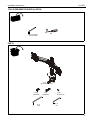
Place four spacers (D) on top of mounting holes
on back of display. (See Figure 5)
Using Phillips screwdriver, carefully install four
M4x25mm screws (C) through corresponding
holes on faceplate, spacers (D) and into the
mounting holes on the display. (See Figure 5)
1.
Adjust head tilt to desired tilt position. (See Figure 7)
2.
Adjust head tilt tension screw to change the adjustment
tension. (See Figure 7)
Pivot Adjustment
(for recessed mounting holes)
1.
Adjust pivot position as desired. (See Figure 7)
2.
Use 3/16" hex key (E) to adjust pivot point tension screws to
change pivot adjustment tension. (See Figure 7)
Arm Height Adjustment
quick connect
faceplate
3
(C) x 4
1.
Adjust arm height to desired level. (See Figure 7)
2.
Use 1/8" hex key (F) to adjust height-adjustable tension
screw to change adjustment tension. (See Figure 7)
NOTE: Cable management cover must be opened in order to
(D) x 4
gain access to height-adjustable tension adjustment
screw.
NOTE: Turn clockwise to reduce tension for lighter displays
and counter-clockwise to increase tension for heavier
displays.
Column Height Adjustment
1.
Figure 5
4.
Position display with faceplate attached above mount. (See
Figure 6)
5.
Slide faceplate onto mounting head until release tab clicks
into place. (See Figure 6)
Turn column height adjustment knob counter-clockwise
until mount can be adjusted vertically on column. (See
Figure 7)
NOTE: Depending on the weight of the displays, height
adjustment may be easier if displays are removed. See
Display Removal Section for details.
2.
Adjust position of mount to desired height. (See Figure 7)
3.
Turn column height adjustment knob clockwise until mount
is securely tightened to column. (See Figure 7)
height-adjustable tension
(under cover)
5
head tilt tension
column height
adjustment knob
pivot point
tension
Figure 6
6.
Repeat Steps 1-5 for second display.
Figure 7
7