1
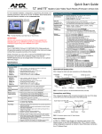
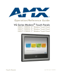
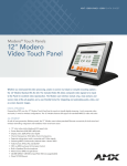
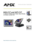
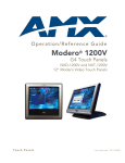
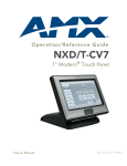
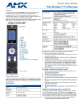
Installation Guide
NXP-PLV Modero® PosiTrack Pilot Camera Controller
For more detailed installation, configuration, programming, file transfer, and
operating instructions, refer to the NXP-PLV Instruction Manual, available online
at www.amx.com.
NXP-PLV Specifications (Cont.)
Rear
connectors
• Footswitch Connector: 1/4" (6.35mm) tip sleeve input jack for
optional momentary footswitch control.
• Mini-USB Connector: 5-pin Mini-USB connector used for
programming, firmware update, and touch panel file transfer
between the PC and the target panel.
• Stereo Output Connector: Stereo output through a 3.5mm minijack (for use with external speakers or headphones).
• Ethernet 10/100 Port: RJ-45 port for 10/100 Mbps
communication.
• USB Connector: Type A USB port connects an external
keyboard or mouse device for use with Virtual PC applications.
• Audio/Video Connector: RJ-45 connection for A/V signals (via
CAT5) between the NXA-AVB/ETHERNET Breakout Box and
the panel.
• Power: 2-pin 3.5 mm captive wire connector.
Button
assignments
Button assignments can only be adjusted in TPD4 and not on the
device’s touchscreen.
• Button channel range: 1 - 4000 button push and feedback
(per address port)
• Button variable text range: 1 - 4000 (per address port)
• Button states range: 1 - 256
(General Button; 1 = Off State, 2 = On State)
• Level range: 1 - 600
(default level value 0-255, can be set up to 1-65535)
• Address port range: 1 - 100
Note: the NXP-PLV reserves channels 1-7 and levels 1-11 on
Port 1 for hardware functions. These channels/levels are
considered reserved by the device and cannot be used for button
assignments.
Certifications
• FCC Class B
• CE
• IEC-60950
Panel LCD
Parameters
•
•
•
•
•
•
•
•
Included
Accessories
• 2-pin 3.5mm captive wire connector (41-5025)
Other AMX
Equipment
•
•
•
•
Overview
The NXP-PLV Modero® PosiTrack Pilot Camera Controller (FG630-100) is an
integrated controller for use with cameras and camera positioning devices, such
as the PTE-300 PosiTrack Camera Controllers. The NXP-PLV connects to the
camera-positioning device and Central Controller via an Ethernet connection.
This connection provides control of the pan/tilt, camera, and lens. The PosiTrack
Pilot can be used in a stand-alone configuration with a Central Controller,
compatible cameras, and positioning systems, or as part of a larger AMX control
system.
Using the graphical interface on the NXP-PLV’s integrated Modero Widescreen
Touch Panel, the operator can select cameras, visually track and change their
movement, store and recall presets and adjust each camera's settings. The
controller also includes a proportional pan/tilt/zoom joystick and controls for
focus, iris and speed. With the right hand on the soft wrist pad, the operator can
also intuitively guide the camera and twist the joystick to zoom the lens in and
out. Simultaneously, the side-mounted control knobs fine-tunes focus, iris and
speed.
The NXP-PLV supports up to six cameras and is an ideal controller for AMX’s
Ethernet-based PTE-300 PosiTrack Pan/Tilt Head.
ATTENTION: Before commencing, verify you are using the latest
NetLinx Master and Modero panel firmware. Also, verify you are
using the latest versions of AMX’s NetLinx Studio and TPDesign4
programs.
Pan/tilt/zoom
control joystick
Camera Station
pushbuttons
Speed knob
Color video touch panel
for video preview and
control interface
Iris Control
knob
Focus Control
knob
FIG. 1 NXP-PLV PosiTrack Pilot Video Panel Camera Controller
Specifications
NXP-PLV Specifications
Dimensions
5" (including joystick) x 17.67" x 8.58" (12.7 cm x 44.88 cm x
21.79 cm)
Weight
5.35 lb. (2.43 kg)
Power
Requirements
• Constant current draw: 1.2A @ 12 VDC
• Startup current draw: 1.8 A
Minimum
Power
Required
1.3 A @12 VDC
Memory
• 64 MB SDRAM
• 256 MB Compact Flash
Enclosure
Plastic with matte charcoal grey finish and plastic rests
Buttons
6 pushbuttons on the left side of the touchscreen to select
cameras
Video Monitor
7-inch (152.40 mm) color active-matrix LCD screen
Video In
NXA-AVB/Ethernet, NXA-AVB Breakout Box required
Compatibility
NetLinx Central Controllers
Operating/
Storage
Environments
•
•
•
•
Operating Temperature: 0° C (32° F) to 40° C (104° F)
Operating Humidity: 20% - 85% RH
Storage Temperature: -20° C (-4° F) to 60° C (140° F)
Storage Humidity: 5% - 85% RH
Aspect ratio: 16 x 9
Brightness (luminance): 350 cd/m2
Channel transparency: 8-bit Alpha blending
Contrast ratio: 200:1
Display colors: 256 thousand colors (18-bit color depth)
Dot/pixel pitch: 0.19 mm
Panel type: TFT Color Active-Matrix
Screen resolution: 800 x 480 pixels (HV) @ 60 Hz frame
frequency
• Video format: NTSC, PAL, and SECAM
• Viewing angles (100° total viewing angle):
• Vertical: + 50° (up from center) and - 50° (down from center)
PTE-300 PosiTrack Pan/Tilt Head (FG630-65)
NXA-AVB Audio-Video Breakout Box (FG2254-10)
Modero Table Top Cable (CA2250-50)
PSN4.4 (FG423-45: recommended power supply)
Product Components
The NXP-PLV is equipped with six external Camera Station pushbuttons, a color
video touch panel, and a 3-axis pan/tilt/zoom joystick, as well as speed control,
iris control, and focus control knobs on the left end of the device. Besides having
an input jack for an optional footpedal, the NXP-PLV also expands upon its
predecessors by including more input and output connections for other
peripheral devices and items. These jacks include a mini-USB port to upload
new applications and pages into the device, a stereo output jack for sound, a
keyboard/mouse port, and a standard Ethernet and NXA-EVB/Ethernet port.
1/4” Input
Port
Mini-USB
Programming
Port
Stereo
output
12VDC
Power
Ethernet Port
(CAT5)
Keyboard/
Mouse Port
FIG. 2 NXP-PLV back view connector layout (close-up)
NXA-EVB/
Ethernet
Audio/Video
(CAT5)
8.
Unpacking the NXP-PLV
1.
2.
3.
Inspect and confirm the contents of the shipment box to verify you have
all specified parts.
Carefully remove the device from the shipping box.
Carefully peel the protective plastic cover from the LCD touchscreen.
NOTE: If the protective plastic LCD cover is not removed, the device may not
respond properly to touch points on the screen or allow proper screen
calibration.
Connecting the NXP-PLV
The NXP-PLV is intended to stand alone on a desktop or tabletop without a
bracket or support platform, but it still needs to communicate with its associated
cameras in order to function. This may be done by connecting it to a NetLinx
master or via a hub or router, but the device still needs to be powered up and
connected before it is fully functional.
1.
2.
3.
4.
Make sure that all data and power wiring connectors are connected to
their respective terminal locations on either the Breakout Box, Ethernet
port, or NetLinx Master.
Connect all data and power wiring connectors to their corresponding locations along the back of the (un-powered) PosiTrack Pilot. Verify that the
terminal end of the power cable is not connected to the a power supply
before plugging in the 2-pin power connector.
Test the incoming wiring by connecting the device connections to their terminal locations and applying power.
Connect the terminal power connector on the 12 VDC-compliant power
supply (PSN4.4 recommended) and apply power.
Wiring a power connection
To use the 2-pin 3.5 mm captive wire connector with a 12 VDC-compliant
power supply (PSN4.4 recommended), the incoming PWR and GND wires
from the external source must be connected to their corresponding locations on
the connector (FIG. 3).
PWR +
Power Supply
GND To the Touch Panel
FIG. 3 NetLinx power connector wiring diagram
1.
2.
3.
Insert the PWR and GND wires on the terminal end of the 2-pin 3.5 mm
captive wire cable. Match the wiring locations of the +/- on both the
power supply and the terminal connector.
Tighten the clamp to secure the two wires.
Verify the connection of the 2-pin 3.5 mm captive wire to the external 12
VDC-compliant power supply.
Configuring Communication
Communication between the NXP-PLV panel and the Master is done using
either USB or ETHERNET (DHCP or Static IP). Ethernet communication can
be achieved through a direct connection. For more information on connecting a
NXP-PLV device to your network, refer to the NXP-PLV User Manual, available
at www.amx.com.
NOTE: USB input devices must be plugged into the rear USB connector before
the device is powered up. The device will not detect a USB connection of this
type until after the unit cycles power.
9.
10.
11.
Obtain the System Number and Master IP Address from NetLinx Studio.
This information must be specific for the system used with the configured
NXP-PLV.
Press the Config button on the main page to open the Panel Setup page.
Press the Protected Setup button (located on the lower-left of the panel
page) to open the Protected Setup page.
Press the System Settings button (located on the Protected Setup page)
to open the System Settings page, and begin configuring the communication settings on the device to match those of the target Master.
NOTE: The mini-USB connector MUST be plugged into an already active NXPPLV before the PC can recognize the connection and assign an appropriate
USB driver. This driver is part of both the NetLinx Studio and TPDesign4
software application installations.
Touchscreen Operation
In addition to the joystick and the side controls, the NXP-PLV has a
touchscreen and six associated Camera Station pushbuttons to control camera
movements and observe the results. Many camera and camera controller
functions, such as presets, may only be accessed through the touchscreen.
For more information on touchscreen features, refer to the NXP-PLV User
Manual, available at www.amx.com.
NOTE: Full touchscreen functionality is only available after download and
installation of the appropriate Cafe Duet module to the master controller. The
module, and the corresponding NetLinx firmware for the NXP-PLV, is available
at www.amx.com.
Presets Page
The Presets page is the first screen to appear when the NXP-PLV is first turned
on. The view screen displays a live input feed from a selected camera if the
camera is already connected to the network.
The Presets buttons at the top of the screen allow you to choose between one
of one hundred previously saved camera subjects.
The Camera Stations external pushbuttons to the left side of the touchscreen
control video feeds from up to six different camera stations: pressing a
particular button switches the device’s influence to that particular station.
Pressing the button for a camera station already selected will change the color
of the accompanying touchscreen tab from green to white, the Config button
on the left disappears, and the joystick and side controls are disabled. Click the
button a second time to re-engage the NXP-PLV.
To select a previously saved preset:
1.
2.
From the Presets page, press a button at the top of the screen to move
the camera to that preset position.
To view more presets, press either the left or right arrow to the sides of
the currently displayed presets. For instance, if you are already at default
presets 1 through 10, press the right button to move to presets 11 through
20, and press the left button to view presets 91 through 100.
To save a new preset or to change an existing preset to a new camera position:
1.
2.
3.
4.
5.
Use the joystick to align the camera to the desired position.
Turn the Focus Control knob to focus the image.
Decide upon a Preset number to be saved.
Press and hold the Preset button for 3 seconds. The device will beep
twice when the preset is saved by the device.
Test the new preset by moving the joystick to move the camera and then
pressing the preset button. If the preset was saved, the camera should
move to the selected area.
Panel Setup and System Connection
1.
2.
3.
4.
5.
6.
7.
From the Main touchscreen page, touch the Panel Setup button to open
the Setup page.
Press the Protected Setup button (located on the lower-left of the panel
page) to open the Protected Setup page and display an on-screen keypad.
Enter the default password 1988 into the keypad’s password field and
press Done when finished.
Press the red Device Number field to open the Device Number keypad.
Enter a Device Number for the panel into the Device Number Keypad.
The default is 10001 and the range is from 1 - 32000.
Press Done to close the keypad, assign the number, and return to the
Protected Setup page.
Press the on-screen Reboot button to restart the device and incorporate
any changes.
For full warranty information, refer to the AMX Instruction Manual(s) associated with your Product(s).
6/08
©2008 AMX. All rights reserved. AMX and the AMX logo are registered trademarks of AMX.
AMX reserves the right to alter specifications without notice at any time.
3000 RESEARCH DRIVE, RICHARDSON, TX 75082 • 800.222.0193 • fax 469.624.7153 • technical support 800.932.6993 • www.amx.com
93-0630-10
REV: C