1
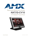
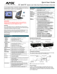
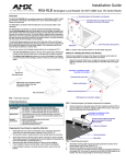
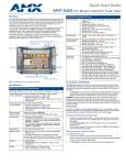
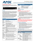
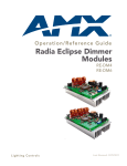
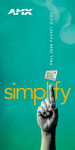
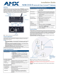
Quick Start Guide
NXD-1000Vi
10” Modero Widescreen Touch Panel w/Full Duplex Intercom
Overview
NXD-1000Vi Specifications (Cont.)
These Color Video (CV) panels display NTSC/PAL/SECAM video formats within
variable sized windows. They include a built-in microphone, speaker, audio/
headphone connector, and 2 NetLinx programmable pushbuttons. Panel to
panel communication is enabled via a full duplex VoIP intercom interface.
Front Panel:
• Light Sensor: Photosensitive light detector for automatic
adjustment of the panel brightness
• Motion Sensor (PIR): Proximity Infrared Detector to wake
the panel when panel is approached
• IR Receiver: 38 KHz and 455 KHz AMX IR frequencies
Operating /Storage
Environments:
•
•
•
•
Included
Accessories:
• Installation Kit for NXD-1000Vi panels (KA2259-02):
- 2-pin 3.5 mm mini-Phoenix connector (41-5025)
- Three Drywall clips (62-5924-05) and #6 - sheet metal
screws (80-0192)
- Four Phillips-head screws (#4-40 x 0.250 Black)
(80-0112)
• NXA-AVB/ETHERNET Breakout Box (FG2254-10)
- Provides video/audio distribution to the A/V panel over
CAT5 cable (up to 200’/60.96 m) and accepts either
Composite or S-Video
• Trim Ring with button openings (60-2259-05)
• Trim Ring without button openings (60-2259-04)
Each panel is sold only as part of a NXD-1000Vi Kit which includes both a panel
and an NXA-AVB/ETHERNET Audio/Video Breakout Box (FG2254-10).
For more detailed installation, configuration, programming, file transfer, and
operating instructions, refer to the NXD-1000Vi Touch Panels operation/
reference guide, available on-line at www.amx.com.
Trim ring - 60-2259-25
Trim ring - 60-2259-26
Speaker
Microphone
Operating Temperature: 0° C (32° F) to 40° C (104° F)
Operating Humidity: 20% - 85% RH
Storage Temperature: -20° C (-4° F) to 60° C (140° F)
Storage Humidity: 5% - 85% RH
Panel Connectors
Sleep button
Microphone
FIG. 2 shows the connectors located on the NXD-1000Vi Modero Video panels.
The Audio/Video RJ-45 connector provides differential audio/video signals
between the touch panel and the NXA-AVB/ETHERNET. This connector routes
Composite video, Stereo (left/right) audio, and microphone audio.
A
Programmable pushbutton/LED
L
12V D C
Sleep button
Programmable pushbutton/LED
E TH E R N ET
10/100
PROGRAM
Speaker
FIG. 1 10" Modero Widescreen Video Touch Panels
Mini-USB
(Program Port)
Specifications
NXD-1000Vi Specifications (FG2259-04)
Dimensions (HWD):
NXD-1000Vi
Stereo
Output
Ethernet
(CAT5)
K E YB O AR D /
M O U SE
A UD IO / V ID EO
PW R
Audio-Video from
NXA-AVB/ETHERNET
Keyboard/Mouse
Power
(CAT5)
USB connector
FIG. 2 Connector layout on the NXD-1000Vi Touch Panels
Install the NXA-AVB/ETHERNET Breakout Box
• Faceplate included: 7.96" x 11.16" x 3.32"
(20.22 cm x 28.34 cm x 8.43 cm)
• Conduit/wallbox: 5.47" x 7.23" x 3.40"
(13.90 cm x 18.40 cm x 8.64 cm) (optional)
Consult the NXA-AVB/ETHERNET Modero Ethernet/Video Breakout Box quick
start guide for required installation methods.
Power Requirements
(stand-alone):
• Constant current draw: 1.3 A @ 12 VDC
• Startup current draw: 1.3 A @ 12 VDC
Consult the NXD-1000Vi Touch Panels operation/reference guide for installation
methodologies and their necessary dimensions.
Minimum power
supply required:
• PSN2.8 Power Supply (FG423-17)
CB-TP10
(FG036-10)
Memory:
• 64 MB SDRAM
• 128 MB Compact Flash (upgradable to 1 GB - factory
programmed)
Weight:
• 2.65 lbs (1.20 kg)
Certifications:
• FCC Part 15 Class B and CE
• IEC60950
Panel LCD
Parameters:
•
•
•
•
•
•
•
•
Viewing Angle:
IR Reception Angle:
Aspect ratio: 16 x 9
Brightness (luminance): 350 cd/m2
Channel transparency: 8-bit Alpha blending
Contrast ratio: 250:1
Display colors: 256 thousand colors (18-bit color depth)
Dot/pixel pitch: 0.28 mm
Panel type: TFT Color Active-Matrix
Screen Resolution: 800 x 480 pixels (HV) @ 60 Hz frame
frequency
• Video format: NTSC, PAL, and SECAM
• 95° total viewing angle
• Vertical: + 45° (up from center) and -65° (down from
center)
• Horizontal: + 50° (left and right from center)
• Vertical: + 30° (up and down from center)
Methods for Installing the NXD-1000Vi
Wiring Guidelines for the NXD-1000Vi Panels
NXD-1000Vi panels use a 12 VDC-compliant power supply to provide power to
the panel via the 2-pin 3.5 mm mini-Phoenix PWR connector. Use the previously
provided power requirement information to determine the power draw.
The incoming PWR and GND wires from the power supply must be connected to
the corresponding locations within the PWR connector.
Note: These units should only have one source of incoming power. Using more
than one source of power to the touch panel can result in damage to the internal
components and a possible burn out. Apply power to the panels only after
installation is complete.
Preparing captive wires
You will need a wire stripper and flat-blade screwdriver to prepare and connect
the captive wires.
Note: Never pre-tin wires for compression-type connections.
1.
2.
3.
Strip 0.25 inch (6.35 mm) of insulation off all wires.
Insert each wire into the appropriate opening on the connector (according
to the wiring diagrams and connector types described in this section).
Tighten the screws to secure the wire in the connector. Do not tighten the
screws excessively; doing so may strip the threads and damage the
connector.
The incoming PWR and GND wires from the external source must be
connected to their corresponding locations on the connector.
9.
10.
11.
1.
Touch Panel Calibration
Wiring a power connection
Insert the PWR and GND wires on the terminal end of the 2-pin 3.5 mm
mini-Phoenix cable. Match the wiring locations of the +/- on both the
power supply and the terminal connector.
Tighten the clamp to secure the two wires. Do not tighten the screws
excessively; doing so may strip the threads and damage the connector.
Verify the connection of the 2-pin 3.5 mm mini-Phoenix to the external 12
VDC-compliant power supply.
2.
3.
The panel is equipped with setup pages that allow you to set and configure
various features on the panel. Consult the NXD-1000Vi Touch Panels
operation/reference guide for detailed information on the Setup pages.
Accessing the Setup and Protected Setup Pages
Press the grey Front Setup Access button for 3 seconds to open the
Setup page.
Press the Protected Setup button. This invokes a keypad for entry of the
password to allow access to the Protected Setup page. Enter 1988 (the
default password), and press Done to proceed.
2.
Note: Clearing Password #5, from the initial Password Setup page, removes
the need for you to enter the default password before accessing the Protected
Setup page.
In the Protected Setup page:
Press the Device Number field to open the Device Number keypad.
Enter a unique Device Number assignment for the panel, and press Done
to return to the Protected Setup page.
Press Reboot to reboot the panel, and apply the new Device Number.
2.
Configuring the Wireless Settings
Consult the NXD-1000Vi Touch Panels operation/reference guide for
configuring the wireless card communication and security settings.
•
•
•
Configuring the Panel’s Wireless IP Settings
Wireless communication using a DHCP Address
Configuring the wireless card for secured access to the WAP
Master Connection
The panel requires you establish the type of connection you want made
between it and your master. In the Protected Setup page:
1.
2.
3.
1.
2.
Select Calibrate.
Touch each target on the screen as they appear. Once calibrated the
panel confirms and instructs you to touch the screen to continue.
Panel Intercom Configuration
Download the module for the intercom panel from www.amx.com, and include
it in your NetLinx project file. For searching purposes, the module manufacturer
is AMX and the model is Intercom.
Note: The intercom module will only work with AMX intercom capable panels.
Advanced Setup
The intercom’s advanced setup pages are accessed through the intercom
setup pages. The advanced pages allow you to set the panel intercom to be
monitored, to monitor other intercom panels, and to name the panel. It is
important to name the intercom panel, the name is displayed in other panels’
intercom call directory pages.
Consult the NXD-1000Vi Touch Panels operation/reference guide for more
intercom setup features.
1.
2.
Setting the Panel’s Device Number
1.
In the Protected Setup page, follow these steps:
Incorporating an intercom capable panel into your NetLinx system
Setup Pages
1.
Set your Password and select Done.
Press the Back button to return to the Protected Setup page.
Press the Reboot button to reboot device and confirm changes.
Select System Settings
Select Type to toggle between USB and Ethernet.
When using Ethernet, press the listed Mode to toggle through the
available connection modes:
Select the Setup button on your intercom page.
On the intercom setup page, press Advanced Setup. This launches the
password numeric keypad.
Enter the password and press Done. The default password is Password 4
of the panel’s firmware Password Setup.
3.
Naming a panel
In the intercom Advanced Setup page:
1.
Press in the area under Panel Name. This launches an on screen
keyboard.
Type the name of the panel and press Done. This is the name that is
displayed in other panels’ intercom call directory pages.
Press Back to return to the intercom setup pages.
Press Exit when you are finished.
2.
3.
4.
Note: The Panel Name is also the G4 Web Control Name and can be set via
the panel’s firmware pages.
Related Documents
•
•
•
•
NXD-1000Vi 10” Widescreen Touch Panel operation/reference guide
VisualArchitect operation/reference guide
G4 PanelBuilder operation/reference guide
TPDesign4 Touch Panel Design Program operation/reference guide
Connection Modes
Mode Description
Procedures
Auto
The device connects to the first
master that responds. This
setting requires you set the
System Number.
Setting the System Number:
1. Select the System Number to open
the keypad.
2. Set your System Number select Done.
URL
The device connects to the
specific IP of a master via a
TCP connection. This setting
requires you set the Master’s
IP.
Setting the Master IP:
1. Select the Master IP number to the
keyboard.
2. Set your Master IP and select Done.
Listen The device "listens" for the
master to initiate contact. This
setting requires you provide
the master with the device’s IP.
4.
5.
Confirm device IP is on the Master URL
list. You can set the Host Name on the
device and use it to locate the device on
the master. Host Name is particularly
useful in the DHCP scenario where the IP
address can change.
Select the Master Port Number to open the keypad and change this
value. The default setting for the port is 1319.
Set your Master Port and select Done.
If you have enabled password security on your master you need to set the
username and password within the device.
6.
7.
8.
Select the blank field Username to open the keyboard.
Set your Username and select Done.
Select the blank field Password to open the keyboard.
For full warranty information, refer to the AMX Instruction Manual(s) associated with your Product(s).
12/07
©2007 AMX. All rights reserved. AMX and the AMX logo are registered trademarks of AMX.
AMX reserves the right to alter specifications without notice at any time.
3000 RESEARCH DRIVE, RICHARDSON, TX 75082 • 800.222.0193 • fax 469.624.7153 • technical support 800.932.6993 • www.amx.com
93-2259-22
REV: B