1
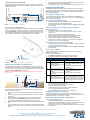
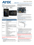
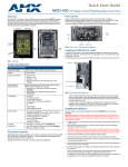
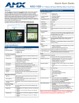
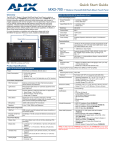
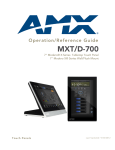
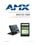
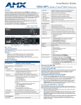
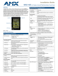
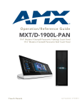
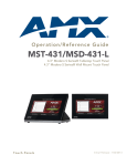
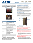
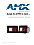
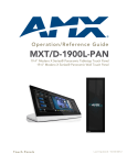
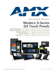
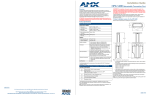
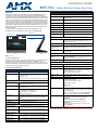
Installation Guide
MXT-700 7" Modero X® Series Tabletop Touch Panel
Overview
MXT-700 (FG5968-04) Specifications (Cont.)
The MXT-700 7” Modero X® Series Tabletop Touch Panel (FG5968-04) provides
several industry firsts, including a beautiful, capacitive multi-touch screen that
provides users access to multiple applications with minimal navigation. The Modero X
Series is the most elegant family of interfaces designed specifically for dedicated room
control. This new generation of touch panels is built for usability offering edge-to-edge
capacitive touch glass with multi-touch capabilities. It features advanced technology
empowering users to operate AV equipment seamlessly, while providing the ultimate
in audio and video quality. The distinctive appearance will complement even the most
sophisticated meeting facilities and homes. With a lightning fast processor, brilliant
graphics and enhanced capabilities, the Modero X Series is the control surface that
simply delivers more.
For more information on installation and configuration, please refer to the
MXT/MXD-700 Operation Reference Guide, available at www.amx.com.
Touch Panel Display (Cont.):
Sleep Button
NFC Sensor
Viewing Angle:
• Vertical: ± 89°
• Horizontal: ± 89°
Screen Resolution
(W x H):
1024x600
Aspect Ratio (W x H):
16x9
Brightness:
400 cd/m2
Contrast Ratio:
800:1
Color Depth:
16,7M colors
Backlight Type:
LED
Touch Overlay:
Projected Capacitive; Multi-touch support, 3 simultaneous
max.
Communications:
Proximity
Sensor
Front
Side
FIG. 1 MXT-700
Ethernet:
10/100 port, RJ-45 connector. Supported IP and IP-based
protocols: UCP, TCP, ICMP, ICSP, IGMP,DHCP, Telnet, FTP,
DNS, RFB (for VNC), HTTP
USB:
2 - USB host 2.0, Type A ports
Near Field
Communications
(NFC):
Supports standards ISO/IEC 15693, ISO/IEC 14443A, ISO/
IEC 14443B; Unique Identifier (UID), Typ Range=.25”,
Max = .5"
Bluetooth:
HID Profile v1.1, Keyboard/Mouse Support, requires MXA-BT
Bluetooth Adaptor
Video:
Supported Video
Codecs:
Common Application
The MXT-700 is intended for boardrooms, conference rooms, or auditoriums where a
panoramic control surface is needed to provide access to multiple functions
simultaneously while remaining elegantly unobtrusive. In residences, it is perfect for
kitchens, home theaters, or home offices where the panoramic control surface can be
used to manage systems throughout the house.
Product Specifications
Streaming/File Formats: MPEG-TS for MPEG-2; HTTP for MJPEG
Audio:
Streaming/File Formats: WAV, MP3 (as part of touch panel file only - no USB storage)
Intercom:
PoE (Power over Ethernet), 802.3af, class 3
Power Consumption:
•
•
•
•
Full-On: 8W maximum
Standby: 3.2 W
Shutdown: 1 W
Startup Inrush Current: Not Applicable due to PoE standard
•
•
•
•
Dimensions (HWD):
Antenna and transceiver for Near Field Communications
device detection and interaction.
Light Sensor:
Photosensitive light detector for automatic adjustment of the
panel brightness.
Motion Sensor:
Proximity detector to wake the panel when it is approached.
• Typical Range: 1 foot (30.48 cm)
• Maximum Range: 3 feet (91.44 cm)
• Range width: 10 degrees
Sleep Button:
Single button on top of panel for placing panel in sleep mode,
for powering off the panel, and for accessing the Settings
Pages.
Microphone:
-42dB ± 3dB sensitivity FET microphone
Speakers:
4 ohm, 2 Watt, 300Hz cutoff frequency
Rear Panel Components:
USB connections:
Ethernet 10/100 Port
and Cable:
2 easily accessible USB ports on rear of base, used for
connection to keyboard, mouse, or other peripherals.
10/100 port, RJ-45 connector through cable extension for
Ethernet connectivity and PoE.
Touch Panel Display:
Display Type:
TFT Active Matrix Color LCD with In-Plane Switching (IPS)
technology.
Display Size:
7.3" x 4.8" (186 mm x 122 mm), 8.8" (222 mm) diagonal
Viewable Area:
6.05" x 3.54" (154 mm x 90 mm), 7.0" (178 mm) diagonal
Operating Temperature: 32° F to 104° F (0° C to 40° C)
Storage Temperature: 4° F to 140° F (-20° C to 60° C)
Humidity Operating: 20% to 85% RH
Humidity Storage: 5% to 85% RH
5" x 7 5/16” x 4 1/8” (126 mm x 187 mm x 105 mm)
Weight:
1.8 lbs (0.82 kg)
Certifications:
•
•
•
•
•
•
•
Included Accessories:
• MXT-700 Installation Guide (93-5968-04)
• MXA-USB-C, USB Port Cover Kit, Modero X Series Touch
Panel (FG5968-18)
• HPG-10 .75-inch HydraPort .75-IN. Grommet (FG570-01)
• MXA-CLK, Modero X Series Cleaning Kit (FG5968-16)
Other AMX Equipment:
• PS-POE-AT, High-Power PoE Injector (FG423-81)
• PS-POE-AF-TC, POE Injector, 802.3af Compliant
(FG423-83)
• MXA-BT Bluetooth USB Adaptor (FG5968-19)
• NXA-ENET8POE, Gigabit PoE Ethernet Switch
(FG2178-62)
• NXA-ENET8-2POE, Gigabit Switch, 8 Port POE, 2 Port
SFP (FG2178-63)
Front Panel Components:
NFC Transceiver:
Full Duplex VoIP, SIP v2.0 (supported with AMX-CSG)
Operating Environment:
MXT-700 (FG5968-04) Specifications
Power:
• MPEG2-TS: MPEG-2 Main Profile @High Level up to 720p
at 25 fps (decode only)
• MJPEG up to 720p at 25 fps (decode only)
FCC Part 15 Class B
C-Tick CISPR 22 Class B
CE EN 55022 Class B and EN 55024
CB Scheme IEC 60950-1
IC
IEC/EN-60950
RoHS
NOTE: The MXT-700-NC (FG5968-27) No Comm touch panel does not have camera
or microphone capability. It otherwise has all of the functionality of the MXT-700 panel.
Panel Connectors and Wiring
7.
Any USB peripherals (mouse, keyboard, etc.) may be connected to one of the two
USB ports on the rear of the device (FIG. 2). Updates to the device’s firmware are also
made via the USB ports.
8.
Tighten the clamp to secure the Ethernet cable. Make sure the clamp is around
the bundled black cable, not the individual wires.
Connect the RJ45 connector to its incoming Ethernet cable and apply power.
Configuring the MXT-700
The MXT-700 is equipped with Settings Pages that allow you to set and configure
various features on the panel. For more information on connecting and configuring the
MXT-700 to a network, please refer to the Modero X Series Programming Guide,
available at www.amx.com.
Accessing the Settings Pages
To access the Settings Pages on the MXT-700, press and hold the Sleep Button
(FIG. 1) on the top of the panel for 3 seconds. The user will be prompted to release the
button to enter the Settings page.
Accessing the Configuration Page
USB Ports
Speaker
Entry for RJ45/
PoE Cable
1.
From the Settings Page, select Configuration. If the Configuration page is
password protected, this opens a password keypad.
Enter the panel password into the keypad (the default is 1988) and select OK to
access the page.
FIG. 2 Connectors on the rear of the MXT-700
2.
Power via Power Over Ethernet
Setting the Panel’s Device Number and Device Name
Power for the MXT-700 is supplied via Power Over Ethernet (PoE), utilizing an AMXcertified, capacitive touch-compliant PoE injector such as the PS-POE-AT High Power
PoE Injector (FG423-81) or equivalent PoE device. If using a PoE injector, the PoE
injector should be installed between the MXT-700 and the incoming Ethernet cable,
and connected to the RJ45 port on the cable attached to the device (FIG. 3).
In the Configuration page:
1.
Press Panel to open the Panel Configuration page.
2.
Ensure that the Synchronize Device Names button is not selected, and click it to
deselect it if it is.
3.
4.
5.
6.
7.
Press Device Number to open the Device Number keypad.
Enter a unique Device Number assignment for the panel and press OK.
Press the Device Name field to open the Device Name keypad.
Enter a unique Device Name assignment for the panel and press OK.
Click the arrow on the top left of the page once to return to the Configuration
page and twice to return to the Settings page.
Accessing the Connection & Networks Page
1.
2.
From the Settings Page, select Connection & Networks. If the page is password
protected, this opens a password keypad.
Enter the panel password into the keypad (the default is 1988) and select OK to
access the page.
Connecting to a Master
The panel requires that you establish the type of connection you want to make
between it and your Master.
In the Connection & Networks page:
1.
Select Master Connection to open the Master Connection page
2.
Press Mode to toggle through the available connection modes:
Connection Modes
Cable length
edited for clarity
RJ45 Port
FIG. 3 Back of the MXT-700, showing RJ45 port and cable for PoE
Mode Description
Procedures
Auto
The device connects to the first
master that responds.
This setting requires that you set
the System Number.
Setting the System Number:
1. Select Master System Number to open
the keypad.
2. Set your Master System Number and
select OK.
URL
The device connects to the
specific IP of a master via a TCP
connection.
This setting requires that you set
the Master’s IP.
Setting the Master IP:
1. Select the Master IP number to the
keyboard.
2. Set your Master IP and select OK.
Listen
The device “listens” for the
Master to initiate contact.
This setting requires you provide
the master with the device’s IP.
Confirm device IP is on the Master URL list.
You can set the Host Name on the device
and use it to locate the device on the master.
Host Name is particularly useful in the DHCP
scenario where the IP address can change.
Ethernet Cable Installation and Modification
In installations where you wish to conceal the Ethernet cable, a hole at least 1.00”
(2.54 cm) in diameter is required in the surface to allow passage of the female RJ45
connector (FIG. 3). If using a smaller hole is unavoidable, you will need to disconnect
the Ethernet cable (ECA5968-05) from the device.
NOTE: The minimum diameter hole through which the Ethernet cable may pass is
0.50" (1.27 cm).
MXT-700
Ethernet Cable
Clamp
Connector
3.
FIG. 4 Bottom of the MXT-700
To disconnect and reconnect the MXT-700’s Ethernet cable to allow use of a hole
smaller than 1.00” in diameter:
1.
On a soft surface, turn the MXT-700 face-down to access the bottom of the
device.
2.
Remove the clamp holding the Ethernet cable (FIG. 4) until the Ethernet cable
moves freely.
3.
Remove the Ethernet cable connector and pull the cable out of the clamp.
4.
Pass the Ethernet cable (ECA5968-05) through the hole, with the RJ45
connector on the other side of the installation surface from the device.
5.
Press the Ethernet cable back into the clamp. Do NOT tighten the clamp at this
time.
6.
Using a nonconductive item such as a wooden stick, reinsert the Ethernet cable
connector into the device. Use the stick to ensure that the connector is properly
seated.
If you have enabled password security on your Master, you need to set the username and password within the device.
a. Select Username to open the Master User keyboard.
b. Set your Username and select OK.
c. Select the Password to open the Master Password keyboard.
d. Set your Master Password and select OK.
e. Press the Back button twice to return to the Settings page.
Configuring the Panel to a Network
The first step is to configure the panel’s communication parameters. This only
configures the panel to communicate with a network, and it is still necessary to tell the
panel with which Master it should be communicating.
Network Communication With a DHCP Address
In the Connection & Networks page:
1.
Select Network Connection to open the Network Connection page.
2.
Toggle the DHCP/Static field until the choice cycles to DHCP. This action causes
all fields on the page (other than Host Name) to be greyed-out.
3.
Select Host Name to open the Host Name keyboard. Enter the new host name
and click OK.
For full warranty information, refer to the AMX Instruction Manual(s) associated with your Product(s).
7/12
©2012 AMX. All rights reserved. AMX and the AMX logo are registered trademarks of AMX.
AMX reserves the right to alter specifications without notice at any time.
3000 RESEARCH DRIVE, RICHARDSON, TX 75082 • 800.222.0193 • fax 469.624.7153 • technical support 800.932.6993 • www.amx.com
93-5968-04
REV: D