1
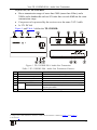
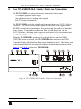
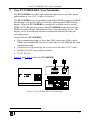
Your PT-110EDID XGA / Line Transmitter
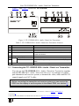
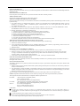
Table 9: PT-110EDID XGA Line Transmitter Features
1
2
3
4
#
Feature
XGA IN 15-pin HD (F) Connector
12V DC
1
EDID
CAPTURE Button
STATUS LED
5
LINE OUT RJ-45 Connector
6
VS Switch
7
HS Switch
8
ON LED
Function
Connect to the UXGA source
+12V DC connector for powering the unit
Press to acquire the EDID information from the display
Illuminates during normal operation; blinks when acquiring the
EDID
Connects to the LINE IN RJ-45 connector on the TP-120
UXGA / Audio Line Receiver
Slide up to set the V SYNC to NEGATIVE polarity;
slide down2 to set the V SYNC to NORMAL polarity
Slide up to set the H SYNC to NEGATIVE polarity (NEG);
slide down 2 to set the H SYNC to NORMAL polarity
Illuminates when receiving power
7.1 Connecting the PT-110EDID XGA / Line Transmitter
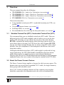
You can use the PT-110EDID XGA Line Transmitter together with the TP-120
XGA Line Receiver 3 to configure an XGA-to-Twisted Pair Transmitter and
Receiver system.
Before connecting the transmitter and receiver system you can acquire the
EDID from the display or set the system to the default EDID, see section 9
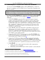
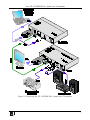
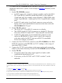
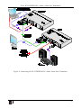
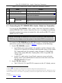
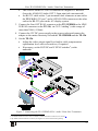
To connect the PT-110EDID XGA Line Transmitter with the TP-120 XGA
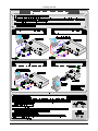
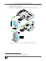
Line Receiver, as the example in Figure 10 illustrates, do the following:
1. On the PT-110EDID, connect the XGA source (for example, the 15-pin
HD output from a computer’s graphics card) to the XGA INPUT 15-pin
HD (F) connector.
2. On the TP-120, connect the XGA OUT 15-pin HD (F) connector to the
XGA acceptor (for example, a monitor).
3. Connect the LINE OUTPUT RJ-45 connector on the PT-110EDID to the
LINE IN RJ-45 connector on the TP-120, via CAT 5 cabling (with a range
of more than 300ft (>100m)).
4. On both 4 the PT-110EDID and the TP-120, connect the 12V DC power
adapter to the power socket and connect the adapter to the mains electricity.
The signal from the XGA source is transmitted via CAT 5 cable, decoded
and converted at the XGA OUT 15-pin HD (F) connector to the XGA
acceptor.
1 See section 9
2 By default, both switches are set down (for normal V SYNC and H SYNC polarity)
3 Download up-to-date Kramer user manuals from our Web site at http://www.kramerelectronics.com
4 For distances of up to 100 meters you can connect a power adapter to either the PT-110 or TP-120. Above it, both sides
should be fed with power
18
KRAMER: SIMPLE CREATIVE TECHNOLOGY