1
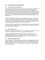
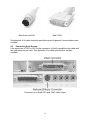
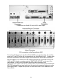
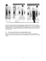
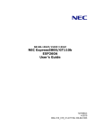
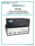
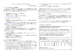
TM
User Manual
2 February 2001
Lightwave Communications, Inc.
100 Washington Street Milford, CT 06460 USA
(800) 871-9838 • (203) 878-9838 • Fax: (203) 874-0157
Email: [email protected] • Internet: www.lightwavecom.com
LCI Asia/Pacific
Postal address: P.O. Box 19 Glen Iris VIC 3146 Australia
Delivery address: 16 Network Drive Port Melbourne VIC 3207 Australia
+61 3 9646 1144 • Fax: +61 3 9645 3377
Email: [email protected] • Internet: www.lightwavecom.com.au
LCI Europe
Zaubzerstraâe 11 Munich D-81677 Germany
+49-89-306-3810 • Fax: +49-89-306-3812
Email: [email protected] • Internet: www.lightwave.de
ServerSwitch 8200 User Manual
Copyright 2000-2001 Lightwave Communications, Inc.
100 Washington St., Milford, CT, 06460, USA
All rights reserved. No part of this copyrighted material may be reproduced in any form or by any means without prior
written permission from Lightwave Communications, Inc.
VDE, VDE/200, ServerSwitch and ServerSwitch 8200 are trademarks of Lightwave Communications, Inc.
Sun® is the trademark of Sun Microsystems, Inc.
1.0
Product Description............................................................................................................. 1
1.1
Video............................................................................................................................... 1
1.2
Keyboard/Mouse............................................................................................................. 1
1.3
Features.......................................................................................................................... 2
1.4
Physical Description ....................................................................................................... 2
2.0
Installing the ServerSwitch 8200......................................................................................... 3
2.1
Location and Operational Safety .................................................................................... 3
2.1.1
Power Requirements.............................................................................................. 3
2.2
System Cable Requirements .......................................................................................... 3
2.3
Connecting Sun® Servers .............................................................................................. 4
2.4
Connecting User Monitors and Keyboard/Mouse Sets .................................................. 6
2.5
Connecting Multiple ServerSwitches .............................................................................. 8
3.0
Operating the ServerSwitch 8200 ..................................................................................... 12
3.1
The On-Screen Menu ................................................................................................... 12
3.2
The LCD Front Panel Display ....................................................................................... 12
3.3
Selecting a Server Port................................................................................................. 13
3.3.1
Disabling One User .............................................................................................. 14
3.3.2
Auto Scan............................................................................................................. 15
3.4
System Setup ............................................................................................................... 15
3.4.1
Set Default Keyboard Type.................................................................................. 16
3.4.2
Auto Scan Duration .............................................................................................. 16
3.4.3
Error Message Duration....................................................................................... 17
3.4.4
Ignore Case in Names/Case Sensitive Names.................................................... 17
3.4.5
Server Name Is Never On/Always On/Temporary............................................... 17
3.4.6
Other Options....................................................................................................... 17
3.5
Port Setup ..................................................................................................................... 18
3.5.1
Naming Server Ports............................................................................................ 18
3.5.2
Toggle Inactive Message on LCD........................................................................ 19
3.5.3
Toggle Auto Scan................................................................................................. 19
3.6
Menu Window Setup..................................................................................................... 20
3.7
Server Window Setup ................................................................................................... 21
Appendix A
Cable Specifications ........................................................................................ 22
Appendix B
Setting Factory Defaults and Flash Update Procedure ................................... 24
B.1
Setting Factory Defaults ............................................................................................... 24
B.2
Flash Update Procedure............................................................................................... 24
Appendix C
Identification of Exterior Components.............................................................. 26
Appendix D
System Specifications...................................................................................... 29
D.1
Physical......................................................................................................................... 29
D.2
Environmental ............................................................................................................... 29
D.3
Electrical ....................................................................................................................... 29
D.4
Interface ........................................................................................................................ 29
D.4.1
Server Ports ......................................................................................................... 29
D.4.2
User Ports ............................................................................................................ 29
D.4.3
Cascade Ports...................................................................................................... 30
D.5
Compliance and Certification........................................................................................ 30
Edition of 2 February 2001
1.0
Product Description
The ServerSwitch 8200 is designed to transport keyboard/mouse and high-resolution
video from up to eight Sun® or compatible computers to video displays and
keyboard/mouse sets for two users. The ServerSwitch 8200 is plug-compatible with
Sun® and compatible computer workstations, video displays, and user devices (such as
keyboards and mice). The ServerSwitch 8200 can be used to create a variety of
networks with no impact on system processing power or performance. Each
ServerSwitch transparently connects video and keyboard/mouse signals between users
and CPUs, allowing two users to sit at separate locations, each with a single monitor,
keyboard, and mouse, and interact with up to 80 CPUs by cascading 10
ServerSwitches. The users may select any of the connected CPUs through an onscreen menu or by using the buttons on the front of the switch. The ServerSwitch 8200
does not lose a CPU port when cascaded; there are special ports dedicated to passing
video, keyboard, and mouse signals in a cascade.
1.1
Video
All video signals are passively transported in real time without any processing or
storage. Additionally, a constant impedance of 75 Ohms is maintained on all video lines
throughout the ServerSwitch 8200 so that video signals are not compromised by
impedance mismatches, as may be found in other switching systems. The
ServerSwitch 8200 also transports monitor sense lines from one user's monitor (user A)
to all attached CPUs, allowing the attached CPUs to perform an automatic, unattended
reboot, even if the CPU is not selected on the switch. Because only one monitor's
sense lines are transmitted to all the attached CPUs, it is recommended that both users'
monitors are identical or have compatible operating modes.
1.2
Keyboard/Mouse
The ServerSwitch 8200 transports all keyboard and mouse signals required by the user
for interaction with any of the attached computers. At any time, a user's keyboard and
mouse are routed only to the CPU selected for that user. However, all CPU ports are
monitored for CPU activity that would require the presence of a keyboard/mouse set
(i.e., a status light change or reboot); the ServerSwitch will send a "keyboard/mouse
idle" response when queried. The keyboard status light (CAPS LOCK, NUM LOCK,
etc.) configuration for each CPU port is maintained within the ServerSwitch, and is sent
to the user's keyboard whenever that CPU port is selected. If the CPU changes the
status light configuration while the port is not selected, the change is saved and will be
displayed correctly when a user selects the port.
The ServerSwitch 8200 will send the language type of the keyboard to attached CPUs
for proper function of CPU operating system applications. The user can either specify
the keyboard language for each ServerSwitch 8200 unit, or let each unit send the
language layout of the keyboard attached to user port A.
1
1.3
Features
The ServerSwitch 8200 features:
§ rack-mountable chassis
§ control up to eight Sun® or compatible workstations with one ServerSwitch
§ control up to 80 Sun® or compatible workstations using 10 cascaded
ServerSwitches
§ two user ports allow simultaneous use of the ServerSwitch from two separate
stations
§ attached CPUs only require one keyboard, mouse, and monitor per user for control
1.4
Physical Description
The ServerSwitch 8200 chassis measures 17.5 inches (44.45 cm) wide by 3.5 inches
(8.89 cm) high by 8.0 inches (20.32 cm) deep. The standard rack mount “ears” allow
mounting in a 19-inch (48.26 cm) rack; the ServerSwitch 8200 requires a free space of
two rack units (2u) for mounting per unit.
An LCD display allows users to check on server status from the front panel. Server
status (powered or unpowered) is displayed on the LCD display.
Users may select server port by using two front panel buttons (in addition to using an
on-screen menu). The buttons also allow the display to toggle between the two users
on the LCD display.
2
2.0
Installing the ServerSwitch 8200
2.1
Location and Operational Safety
The ServerSwitch 8200 may be mounted in a rack, or may be used as a desktop unit. If
used as a desktop unit, the rack mount "ears" may be removed, and rubber feet
(supplied with the ServerSwitch 8200) should be attached. If mounting the unit in a
rack, ensure that there are screws in each of the mounting holes and that the "ears" are
firmly seated against the rack once the screws are tightened. Make sure that at least
four inches (10 cm) of space exists behind the rear panel of the ServerSwitch 8200 to
prevent excessive bending of cables. More space may be required depending on the
cables used.
The ServerSwitch 8200 is designed to work in temperatures less than 122°F (50°C).
The unit is cooled by convection through slots in the enclosure sides. Make sure the
slots are not obstructed or clogged. If mounting in a rack, forced ventilation by rackmounted fans is recommended, especially when mounted with other equipment. The
ServerSwitch generates 102.4 BTU/hr heat in normal operation.
The cover should not be removed due to potentially hazardous voltages inside the unit.
There are no user-serviceable parts inside. Return the unit to Lightwave for repairs to
avoid cancellation of the warranty.
2.1.1 Power Requirements
Properly and reliably ground all equipment. This is especially important when the unit is
not directly connected to power mains (i.e., when a power strip is used).
The ServerSwitch 8200 requires 100-240 VAC, 30 Watts, and 50/60 Hz. Power is
provided through the AC power cord included with the unit. Before using the
ServerSwitch 8200, the power cord must be plugged into the power input jack on the
back of the unit and into an AC power outlet.
2.2
System Cable Requirements
For most applications, Sun® Servers will have both video and keyboard/mouse cables
directly connected to the ServerSwitch 8200. The ServerSwitch 8200 requires 8-pin
Mini-DIN cables with two male ends for keyboard/mouse, and 13W3 or HD15 cables
with two male ends for video. If the unit will be in a cascade, then a DB9 serial data
cable is also required.
3
Male 8 pin mini-DIN
Male 13W3
See Appendix A for cable technical specifications and Lightwave Communications part
numbers.
2.3
Connecting Sun® Servers
If the server has a 13W3 or HD15 video connector, a Sun® compatible video cable with
two male ends may be used. See Appendix A for cable specifications and part
numbers.
Connectors on a Sun® CPU with 13W3 video output
4
Connectors on a Sun® CPU with HD15 video output
CPU connectors on the ServerSwitch 8200
Connecting Sun® servers to the ServerSwitch 8200 is very simple. First, be sure that
power is off to all CPUs that will be connected to the ServerSwitch 8200. A video cable
should be connected to the video output of the Sun® server that will be connected to
the ServerSwitch. The other end of the cable should then be connected to one of the
13W3 or HD15 female connectors marked “SWITCHED INPUTS” on the rear of the
ServerSwitch. An 8 pin mini-DIN cable should then be connected to the
keyboard/mouse output of the server, with the other end connected to the “SWITCHED
INPUTS” keyboard/mouse input port above the previously connected video port on the
ServerSwitch 8200. Repeat this process for each server that is to be attached to the
ServerSwitch.
5
CPU connections to the ServerSwitch 8200 using 13W3 and HD15 video cables
Lightwave Communications recommends using cables less than 75 feet in length to
connect Sun® servers to the ServerSwitch 8200. Lengths over 75 feet cause significant
signal degradation. If the ServerSwitch 8200 and attached server must be more than
75 feet apart, use Lightwave Communications’ VDE/200 to extend the useful range of
the video signal.
2.4
Connecting User Monitors and Keyboard/Mouse Sets
Monitors and keyboard/mouse sets for both ServerSwitch 8200 users should be
identical to prevent incompatibility issues from degrading users' access to the attached
servers.
6
User A properly paired
User B properly paired
Before starting, be sure that power is off to the ServerSwitch 8200 and the users'
monitors. The users' monitors are attached to the two 13W3 connectors marked
"USER" on the rear of the ServerSwitch 8200. The keyboard/mouse sets are attached
to the two 8 pin mini-DIN connectors marked "USER". Be sure that the monitor and
keyboard/mouse set for each user are properly paired to the user output ports (i.e., user
A is connected to the 13W3 and 8 pin mini-DIN ports marked "A" and not to one of the
ports marked "B"). If the user’s monitor has an HD15 video connector, then a 13W3 to
HD15 converter cable must be used. Be sure that the cable transmits all video signals
properly.
Cable connections to a ServerSwitch 8200 as a stand-alone unit
7
2.5
Connecting Multiple ServerSwitches
In each cascade, there is a master unit, and one or more auxiliary units. The users are
directly attached to the master unit, and can control and access all the auxiliary units
through that master unit. There may be up to 9 auxiliary units in a cascade along with
one master unit, allowing the two users to control 80 CPUs.
To connect several ServerSwitches in a cascade, first select the unit that will be the
master unit. The monitors and keyboard/mouse sets for the users will be directly
attached to this unit. Be sure that the monitors are identical or at least have compatible
operating modes, as user B will most likely not be able to use his monitor if the monitors
are incompatible.
Attach a DB9 serial data cable to the CONTROL OUT port on the back of the master
unit. Be sure to secure the cable to the port using the screws on the cable. Attach the
serial data cable from the master unit to the CONTROL IN port on the first auxiliary unit
in the cascade, and secure the cable to the port. Attach the serial cable from the
CONTROL OUT port of the auxiliary unit closest to the master in the cascade (the
upstream unit) to the CONTROL IN port of the auxiliary unit further away from the
master in the cascade (the downstream unit), and repeat until all units in the cascade
are connected. The last unit in the cascade will only have a serial cable attached to the
CONTROL IN port.
Cable connections to a cascade master unit
8
Cable connections to a cascade auxiliary unit
Cable connections to the end cascade auxiliary unit
9
Attach two 13W3 video cables to the two user video ports on the back of the last
auxiliary unit in the cascade, and secure them to the ports using the screws on the
cable connector. Attach the other ends of the cables to the CASCADE IN video ports
on the next auxiliary unit closer to the master unit (the next unit upstream). Be sure that
the USER A port is attached to the CASCADE IN A port, and the USER B port is
attached to the CASCADE IN B port. Repeat this process, connecting the CASCADE
IN ports of auxiliary units further away from the master (downstream units) to the USER
video ports of those auxiliary units closer to the master (upstream units), until all units in
the cascade are connected. The master will have two video cables attached to its
CASCADE IN ports, and the users' monitors connected to the USER video ports.
Master unit with cables
Auxiliary unit with cables
10
End auxiliary unit with cables
Note that there are no keyboard/mouse lines connected between cascaded units.
Keyboard and mouse signals are transported over the serial cables attached to the
CONTROL ports.
Once all units are attached in the cascade, turn on power to the users' monitors, and
then power up the master unit. Once the master unit has completed its power-on
diagnostic, power up the auxiliary units in succession down the cascade. After the
auxiliary units have each completed their power-on diagnostics, press Control
Control and
Alt Graph simultaneously on one of the user keyboards to display the ServerSwitch
8200 on-screen menu. Scroll down the port numbers on the menu; ports for auxiliary
units are displayed by selecting Next unit from the bottom of the on-screen menu.
All ports for the master and auxiliary units should be present. If all ports after a
particular auxiliary unit are missing, check the CONTROL port connections between that
unit and the unit immediately downstream. If this fails to restore those downstream
ports, then try changing the cascade position of the last unit that works. If this fails also,
and no ports downstream from that unit are present, then contact Lightwave
Communications for technical support.
If all ports are present, turn off power to all ServerSwitch 8200 units and the user
monitors. Begin connecting the servers to the units as outlined in section 2.3,
Connecting Sun® Servers. Start at SWITCHED INPUT port 1 on the master unit, and
proceed sequentially from there (i.e., fill ports 1 through 8 on the master, then 1 through
8 on the first auxiliary, etc.). Once all servers have been connected, the ServerSwitch
8200 cascade is ready for use. Input ports may be named as outlined in section 3.4,
Naming CPU Ports.
If installing more CPUs to an existing ServerSwitch 8200 cascade, it is not necessary to
power down the switch. The server that will be attached should be not be powered until
the keyboard/mouse and video cables are connected to the ServerSwitch 8200.
If adding another ServerSwitch 8200 to an existing cascade, it is not necessary to
power down the cascaded units or any of the servers attached to the existing cascade.
11
3.0
Operating the ServerSwitch 8200
The ServerSwitch 8200 is designed to allow two users to access and control up to 80
Sun® or compatible servers. The users may select the servers either from the frontpanel buttons or an on-screen menu. The individual CPU ports may have names
associated with them to allow for more intuitive access of the attached CPUs.
3.1
The On-Screen Menu
The on-screen menu is accessed by pressing Control and Alt Graph
simultaneously. In addition to accessing server ports, the users may assign names to
individual ports, configure the appearance of the on-screen menus, update the software
stored in flash memory, and view system information.
Note: When the on-screen menu is active, the Compose, Num Lock, Caps Lock, and
Scroll Lock status lights will flash on and off in unison to indicate the menu is selected.
The user may exit from the first on-screen menu at any time by pressing the <ESC> key.
Pressing the <ESC> key while in any other menu beside the first on-screen menu will
back the user out by one level. To select a menu item, the user may use the up and
down arrow keys to move the highlight bar to the desired item and press <ENTER>,
<ENTER> or
press the highlighted character for the menu item.
Use of the various options and functions of the on-screen menu is covered in the
following sections.
3.2
The LCD Front Panel Display
The LCD display allows users to view the currently selected server port. The port name
defined by the users is shown on the display rather than the port number. Only one
user is displayed at a time, with user A shown by default at start-up. To change
between user A and user B, press the up arrow and down arrow buttons simultaneously
and then release.
The bottom two lines of the LCD display contain information about the servers attached
to the ServerSwitch 8200. The ServerSwitch automatically scans through all the server
ports (the master unit in a cascade will scan through all master and auxiliary ports). As
each port is scanned, its assigned name and port number are displayed on the bottom
line. The ServerSwitch also checks if power can be detected through the
keyboard/mouse cable, and shows whether power is detected for each port on the
display line above the port name and number.
Additionally, the LCD display will show the system boot code version number and the
flash memory check message at power on. The LCD display should change to show
the user-selected port within 10 seconds after power on.
12
3.3
Selecting a Server Port
The users have two means to select a server port: the front panel buttons and the onscreen menu.
The front panel buttons will increment or decrement the server port number for the
selected user. If a port has been selected by the other user on the ServerSwitch, then it
will not appear as the user scrolls through the server ports using the front panel buttons.
One user at one time may select a server port using the front panel buttons; to switch
between user A and user B, press both the up arrow and down arrow buttons
simultaneously, and then release. Using the front panel buttons to select a server port
can be rather slow, especially when many units are cascaded, so most users will
probably prefer to use the on-screen menus to select a server port.
The on-screen menu provides two methods for users to select a server port. Users may
scroll through all the available server ports using the keyboard arrow keys and pressing
<ENTER> to select a port, or may directly jump to a specific port.
Lightwave Communications
Inc.
Curr:
1
8200 System setup...
no Auto scan
Jump to port...
Disabled
Port
Port
1
2
Port
Port
Port
Port
Port
3
4
5
6
7
Port
8
Esc exits
On-screen Menu for Stand-alone Unit
When the on-screen menu is first brought up, it shows the currently selected server
port, a few menu options, and the server ports and associated names for the
ServerSwitch 8200. If there are several ServerSwitches arranged in a cascade, then
13
only those server ports available on the master unit are shown on the first screen (other
ports are shown by selecting Next unit at the bottom of the menu).
Pressing J or selecting Jump to port… from the menu allows a user to directly select
a server port. The ServerSwitch will prompt the user for a server port by changing Jump
to port… to Enter port: on the on-screen menu. At this prompt, the user should
enter either the port name (which may or may not be case-sensitive according to other
system settings) or the port number and press <ENTER>.
<ENTER> If a device is selected that is
currently in use by the other user, the message Port In Use by Other User will
appear at the bottom of the screen and the port will not be selected; however, the onscreen menu will remain. The user should try to select another port or exit from the
menu by pressing the <ESC> key.
Alternately, the user may select a server port by moving the highlight bar over a server
port name with the up and down arrow keys and pressing <ENTER> to select that port.
If a device is selected that is currently in use by the other user, the message Port In
Use by Other User will appear at the bottom of the screen, and the port will not be
selected. For a group of cascaded ServerSwitches, the first on-screen menu will only
show those server ports available on the master unit; the server ports for the auxiliary
units are accessed by selecting Next unit from the bottom of the on-screen menu, or
by pressing the highlighted character (N
N). Each menu that follows shows the server
ports for one auxiliary unit. The menu item Next unit will bring the user to the next
unit in the cascade, while the menu item Prev unit (or pressing the highlighted
character, P) shows the ports for the previous unit in the cascade. The current
ServerSwitch selected in the cascade is indicated at the top of the menu as Curr: X,
X
where X is the number of the unit in the cascade. The master unit is unit 1; the next
auxiliary unit is 2, and so on. The user may exit from the port selection menus and back
to the main menu by pressing the <ESC> key.
Once a server port is selected, the on-screen menu will disappear. With the default
settings, a small box with the port name will appear at the top of the screen when the
on-screen menu disappears, and then disappear a few seconds later. This box with the
server port name may be configured to never appear, to appear for a few seconds, or to
always remain on the screen; its position and colors may also be configured. See
section 3.7 for more information.
3.3.1 Disabling One User
At start-up, server port 1 is selected by user A, and user B is disabled. User B actually
has a special port selected: the "parking" port. The parking port allows two users to
exist on the system without requiring that a server port always be selected, freeing all
server ports for possible selection when a user is not active.
The parking port may be selected by choosing the Disabled item just above the first port
in the port selection list on the main menu. Both users may select this item
simultaneously. It is recommended that a user select this item when not active to
prevent a server port from being blocked from the other user.
14
3.3.2 Auto Scan
The ServerSwitch can automatically scan through each attached server in auto scan
mode. Servers may be individually selected for inclusion in the auto scan; all server
ports are selected by default. See section 3.5.3 for more information on selecting
server ports for auto scan.
A user may begin auto scan by pressing A at the on-screen menu to change no Auto
scan to start Auto scan.
scan Once the user exits from the on-screen menu by
pressing <ESC>,
<ESC> the auto scan will begin. The ServerSwitch will pause at each server
for the duration specified by the Auto scan duration setting outlined in section
3.4.1. As the ServerSwitch displays each server port, its name and number will appear
as set by the user, or may not appear if the port name is set to Never On (see section
3.4.4). The user may stop the auto scan by pressing any key. Note that only those
servers that are powered and do not have their video output disabled (i.e., in suspend or
screen saver mode) will display video in auto scan mode. In addition, if the other user
has a port selected, then it will not be displayed in the auto scan.
3.4
System Setup
8200 System Setup
Version
3.17
Set Default Keyboard Type
Auto scan duration:
10 sec
Error Message duration: 5 sec
ignore Case in names
Server Name is Temporary
Port setup...
menu Window setup...
Server window setup...
Esc exits
System Setup Menu
The System Setup menu is accessed from the main on-screen menu. The menu
allows users to change system options for the ServerSwitch 8200, view the flash
software version, and access the flash update and factory defaults menu. The flash
15
software version is listed at the top of the System Setup menu. See Appendix B,
Setting Factory Defaults and Flash Upgrade Procedure for more information.
Settings in the System Setup menu are automatically saved each time the user exits
from the menu.
3.4.1 Set Default Keyboard Type
Set Default Keyboard Type
US default
UNIX
French
Danish
German
Italian
Netherlands
Norwegian
Portuguese
Current: US
Spanish
Swedish/Finnish
Swiss/French
Swiss/German
UK
Korean
Taiwan
Japan
Canadian
default
Esc exits
Default Keyboard Type Menu
Sun© CPUs can support different keyboard languages. Keyboards for different
languages have different key layouts; the keyboard layout is determined at the CPU
boot time. This option determines the keyboard layout type sent when the CPU
requests the data at boot time. By default, the ServerSwitch 8200 will send the
language layout of the keyboard attached to user port A last time the ServerSwitch was
power cycled.
3.4.2 Auto Scan Duration
This option determines the amount of time that each server port is displayed during auto
scan. Users may change this value either by pressing the highlighted character (A
A) or
moving the highlight bar to the option and using the + or – keys to change the value.
Pressing the highlighted character will increment the time until it reaches the highest
value, and then start again at the lowest value. The default value is 10 seconds.
16
3.4.3 Error Message Duration
This option determines the amount of time each error message will appear on the front
panel LCD display. Users may change this value either by pressing the highlighted
character (M
M) or moving the highlight bar to the option and using the + or - keys to
change the value. Pressing the highlighted character will increment the time until it
reaches the highest value, and then start again at the lowest value. Using the + and keys allows users to increment or decrement the value. The default value is 5 seconds.
3.4.4 Ignore Case in Names/Case Sensitive Names
Users may specify whether or not case is ignored when typing a server port name for
the Jump to port… option. If case is not ignored, then the users must type the server
port names exactly as they appear within the ServerSwitch 8200 memory. This option
is changed either by pressing the highlighted character (C
C) while the System Setup
menu is on the screen, or by moving the highlight bar to the option and using the + and
- keys to change the value.
3.4.5 Server Name Is Never On/Always On/Temporary
The server port name may be set to never display, always display, or display for a few
seconds and then disappear when the port is selected. If the port names have not been
changed by the users, then the default port names will be displayed instead. This
option is changed either by pressing the highlighted character (N
N) while the System
Setup menu is on the screen, or by moving the highlight bar to the option and using the
+ and - keys to change the value.
3.4.6 Other Options
The System Setup menu also allows users to access three other setup menus. Users
may configure individual server port parameters (such as port names) by selecting
Port setup… from the menu. The position and appearance of the on-screen menu
may be configured by selecting menu Window setup…,
setup… and the position and
appearance of the server port name window may be configured by selecting Server
window setup… from the System Setup menu.
17
3.5
Port Setup
Port Setup
Edit Port Names
+Port
1
+Port
2
+Port
3
+Port
4
+Port
5
+Port
6
+Port
7
+Port
8
F8 toggles Inactive msg
+/keypad + or – toggles autoscan
Enter to edit port name
: Port Autoscan Enabled
Esc exits
Port Setup Menu
In addition to changing server port names, users may also configure other parameters
from the Port
Port Setup menu. Users may enable or disable auto scan for each port, and
may prevent the front panel LCD display from showing error messages for inactive
server ports.
3.5.1 Naming Server Ports
Users may name server ports to allow a more intuitive use of the ServerSwitch 8200.
Server port names replace the simple default port numbers wherever the server port is
identified. Server port names are especially useful when using the Jump to port…
function from the main menu. However, users should be careful when using server port
names with this function, as server port names can be set to be case-sensitive (see
section 3.4, System Setup for more information).
Users may name server ports by first selecting System setup… from the main onscreen menu. To access the server port setup, which includes the option to change
port names, select Port setup… from the menu that appears.
18
The Port Setup menu allows users to change several options for each port. To
change the server port name, use the up and down arrow keys to move the highlight bar
to the desired server port, and press <ENTER> to select that server port for change.
The user may enter the new server port name once the highlight bar changes to show
only the server port name. The new server port name overwrites the old server port
name; if the new server port name is shorter than the old name, then the user must
erase the remaining characters by pressing delete. Press the <ENTER> key after typing
the new server port name to change the name, or press <ESC> to discard the change
and exit back to the Port Setup menu.
3.5.2 Toggle Inactive Message on LCD
If the ServerSwitch detects that there is no power from the attached servers on the
keyboard/mouse lines, or if no server is present, then the ServerSwitch will indicate that
port as inactive on the front panel LCD. The user may want to prevent this message
from appearing on the front panel to reduce possible confusion. In the port setup menu,
move the highlight bar to the port and press F8 to toggle the inactive message on or off.
If the message is on, a + will appear next to the port name; if it is off, a – will appear
next to the port name. All ports have the inactive message enabled by default.
3.5.3 Toggle Auto Scan
Individual port may be selected or deselected for inclusion in the auto scan. In the port
setup menu, move the highlight bar to the port and press + to enable auto scan and – to
disable auto scan. A symbol next to the port name indicates that the port is enabled
for auto scan. All ports are enabled by default.
19
3.6
Menu Window Setup
Menu Window Setup
move
move
move
move
Up
Down
Left
Right
Background color
Foreground color
Highlight color
Select menu color
Esc exits
Menu Window Setup Menu
Users may alter the appearance of the menu windows by selecting this option. The
colors and position of the menu can be altered to suit the users' preferences. Each
user's preferences are stored separately, so each user may specify a different
appearance for their individual menus.
When in the Menu Window Setup menu (reached from the System Setup menu),
users may change the appearance and position of the menu window by moving the
highlight bar to the desired parameter with the up and down arrow keys, and pressing
the <ENTER> key, or by pressing the key for each option's highlighted character. For
the position options (move
move Up,
Up move Down,
Down move Left,
Left and move Right)
Right each time
<ENTER>
<ENTER> or the highlighted character is pressed, the menu window will move one place
in the direction selected. For the color options (Background
Background color,
color Foreground
color,
color Highlight color,
color and Select menu color),
color each time <ENTER> or the
highlighted character is pressed, the color will cycle through one choice for the property
selected. Once finished altering the appearance of the menu, the user may exit by
pressing the <ESC> key.
20
3.7
Server Window Setup
Users may alter the appearance and position of the window that displays the server port
name on-screen when a server port is selected.
When Server window setup… is selected from the System setup menu, the large
menu disappears and a small window that is the same size and shape as the server
name window will appear with the move Up option in it. Only one option at a time will
appear in the window. Users may select which option to alter by pressing the up and
down arrow keys and pressing <ENTER> to change that option once; position will move
by one place, and color will cycle through once choice. Users may also press the
highlighted character associated with that option to select it, but they must press
<ENTER> to change it. Position and color parameters are the same for the Server
window setup and menu Window
Window setup options, except Server window setup
is missing Highlight color,
color since this is not used in the server name window.
21
Appendix A
Cable Specifications
This appendix outlines the required cable specifications for the ServerSwitch 8200.
Additionally, part numbers for cables available from Lightwave Communications are
provided.
Serial Cables:
A serial data cable is provided with each ServerSwitch 8200. This cable may be used
either to connect the unit in a cascade or to update the software in flash memory. If
another cable must be used, be sure that all wires are present and connect straight
through; a cable with crossed lines (e.g. a null modem cable) will not work.
Keyboard/Mouse Cables:
Cables with two male 8-pin mini-DIN connectors must be used. No other cable type is
supported.
Video Cables:
Video cables must have all pins to ensure proper function (some vendors' video cables
do not have all monitor ID lines). Monitors with HD15 connectors may be used with the
ServerSwitch 8200 if an LCI adapter cable or adapter (listed below) is used.
The following table lists the descriptions and Lightwave Communications part numbers
of cables that may be used with the ServerSwitch 8200. Contact Lightwave for current
prices.
Description
Part Number
Sun (PCI) HD15M to 13W3M Video Cable, 2M (6.6')
Sun (PCI) HD15M to 13W3M Video Cable, 3M (9.8’)
Sun (PCI) HD15M to 13W3M Video Cable, 4M (15’)
Sun (PCI) HD15M to 13W3M Video Cable, 7.6M (25’)
Sun (PCI) HD15M to 13W3M Video Cable, 10M (32.8’)
Sun Ultra 5/10 HD15F to 13W3M Video Adapter
Sun Ultra 5/10 HD15M to 13W3F Video Adapter
Sun HD15F, VGA to 13W3M (extension), 7.6M (25’)
SGI, Sun 13W3 to 13W3, MM, 1M (3.3')
SGI, Sun 13W3 to 13W3, MM, 2M (6.6')
SGI, Sun 13W3 to 13W3, MM, 3M (9.8')
SGI, Sun 13W3 to 13W3, MM, 4M (15')
SGI, Sun 13W3 to 13W3, MM, 10M (32.8')
SGI, Sun 13W3 to 13W3, MM, 15M (49.2')
SGI, Sun 13W3 to 13W3, MM, 18M (59.1')
SGI, Sun 13W3 to 13W3, MM, 23M (75.5')
SGI, Sun 13W3 to 13W3, MM, 30M (98.4')
SGI, Sun 13W3 to 13W3, MF (extension), 1M (3.3')
SGI, Sun 13W3 to 13W3, MF (extension), 2M (6.6')
SGI, Sun 13W3 to 13W3, MF (extension), 4M (15')
SGI, Sun 13W3 to 13W3, MF (extension), 3M (9.8')
SGI, Sun 13W3 to 13W3, MF (extension), 10M (32.8')
SGI, Sun 13W3 to 13W3, MF (extension), 15M (49.2')
SGI, Sun 13W3 to 13W3, MF (extension), 18M (59.1')
SGI, Sun 13W3 to 13W3, MF (extension), 23M (75.5')
SGI, Sun 13W3 to 13W3, MF (extension), 30M (98.4')
200.0184
200.0185
200.0186
200.0187
200.0190
200.1395
200.1397
200.0188
200.1302
200.1304
200.1306
200.1308
200.1310
200.1312
200.1313
200.1314
200.1316
200.1301
200.1303
200.1305
200.1307
200.1309
200.1311
200.1315
200.1317
200.1318
22
HD15 Video Cable, MM 2M (6’)
HD15 Video Cable, MM 3M (10’)
HD15 Video Cable, MM 4.5M (15’)
HD15 Video Cable, MM 7.6M (25’)
HD15 Video Cable, MM 15M (50’)
HD15 Video Cable, MF (extension) 2M (6’)
HD15 Video Cable, MF (extension) 3M (10’)
HD15 Video Cable, MF (extension) 7.6M (25’)
HD15 Video Cable, MF (extension) 15M (50’)
HD15 Video Cable, MF (extension) 23.3M (75’)
Sun Keyboard Cable, 8 pin Mini-DIN, MM, 2M (6.6')
Sun Keyboard Cable, 8 pin Mini-DIN, MM, 3M (9.8')
Sun Keyboard Cable, 8 pin Mini-DIN, MM, 4.6M (15')
Sun Keyboard Cable, 8 pin Mini-DIN, MM, 8M (26.3')
Sun Keyboard Cable, 8 pin Mini-DIN, MM, 10M (32.8')
Sun Keyboard Cable, 8 pin Mini-DIN, MM, 15M (49.2')
Sun Keyboard Cable, 8 pin Mini-DIN, MM, 23M (75.5')
Sun Keyboard Cable, 8 pin Mini-DIN, MM, 30M (98.4')
Sun Keyboard Cable, 8 pin Mini-DIN, MM, 18M (59.1')
Sun Keyboard Cable, 8 pin Mini-DIN, MF (extension), 2M (6.6')
Sun Keyboard Cable, 8 pin Mini-DIN, MF (extension), 3M (9.8')
Sun Keyboard Cable, 8 pin Mini-DIN, MF (extension), 4.6M (15')
Sun Keyboard Cable, 8 pin Mini-DIN, MF (extension), 8M (26.3')
Sun Keyboard Cable, 8 pin Mini-DIN, MF (extension), 10M (32.8')
Sun Keyboard Cable, 8 pin Mini-DIN, MF (extension), 15M (49.2')
Sun Keyboard Cable, 8 pin Mini-DIN, MF (extension), 23M (75.5')
Sun Keyboard Cable, 8 pin Mini-DIN, MF (extension), 30M (98.4')
Sun Keyboard Cable, 8 pin Mini-DIN, MF (extension), 18M (59.1')
23
200.1531
200.1533
200.1541
200.1535
200.1570
200.1530
200.1532
200.1534
200.1536
200.1537
200.8002
200.8004
200.8006
200.8008
200.8010
200.8012
200.8014
200.8016
200.0018
200.8003
200.8005
200.8007
200.8009
200.8011
200.8013
200.8015
200.8017
200.8019
Appendix B
Setting Factory Defaults and Flash Update Procedure
B.1 Setting Factory Defaults
If it becomes necessary to reset the ServerSwitch 8200, the users may do so from the
System Setup menu. Once at the System Setup
Setup menu, access the defaults/flash
update menu by pressing the <F1> key. Press and hold the <F12> key, and then press
the Y key to confirm that the ServerSwitch parameters and server port names should be
set to the factory default values. The on-screen menu will temporarily disappear while
all parameters are reset, and will reappear at the main on-screen menu once the
parameters are reset. The ServerSwitch will not be able to switch to another port or
pass keyboard/mouse signals during the reset to factory defaults.
B.2 Flash Update Procedure
The flash update feature allows the user to install newer versions of operating software
in the ServerSwitch 8200 without removing the unit from its installation. New software
revisions will be released from time to time to add features to the ServerSwitch 8200 or
make changes for customer requests. Note that the users will not be able to switch
server ports during the update.
The binary file for the flash update can be downloaded from
ftp://ftp.lightwavecom.com/pub/products/8200/software/
Materials:
§ Laptop or other computer with RS-232 serial I/O port
§ Serial cable with DB9 male end and mating connector for the above computer's
serial port
§ Communications software capable of XMODEM uploads
§ ServerSwitch 8200 software update file
DB9 cable connected for flash update
24
1. Connect the laptop serial port to the CONTROL IN port of the ServerSwitch
8200. Start the communications software, and configure the communications
parameters to 38,400 baud, 8 data bits, no parity, 1 stop bit, and DTE (38.4K
8N1 DTE). Select the correct serial port (i.e., COM1) as the I/O port if not
already selected.
2. From a ServerSwitch 8200 user port (either A or B will work), access the main
on-screen menu by pressing <CONTROL> and <ALT GRAPH> simultaneously.
Select System Setup from the on-screen menu. From the System Setup
menu, press the <F1> key to access the defaults/flash update menu. Press the
F key to put the ServerSwitch 8200 in flash update mode.
3. Once the F key has been pressed, the ServerSwitch 8200 sends a message
through the serial port prompting the user to send the binary update file, but there
is no confirmation through the user's on-screen menu that the flash update has
begun. Begin uploading the flash update binary file from the computer attached
to the CONTROL IN port to the ServerSwitch 8200. When the ServerSwitch
8200 has received the entire file, it will prompt the user through the serial port to
confirm that the file is correct. Once the file version is confirmed, the system will
program the flash and restart.
25
Appendix C
Identification of Exterior Components
Front:
Rear:
First Chassis Revision
26
Second Chassis Revision
Third Chassis Revision
Key to Rear View:
1.
2.
2A.
3.
4.
4A.
5.
6.
6A.
server keyboard/mouse (8 pin mini-DIN)
server video in (13W3 or HD15)
server video in (13W3 only)
user A keyboard/mouse (8 pin mini-DIN)
user A video out (13W3)
user A video out (13W3 or HD15)
user B keyboard/mouse (8 pin mini-DIN)
user B video out (13W3)
user B video out (13W3 or HD15)
27
7.
8.
9.
10.
11.
12.
13.
cascade control in (DB9)
cascade video A in (13W3)
cascade control out (DB9)
cascade video B in (13W3)
power switch
AC power input jack
AC power input fuse
28
Appendix D
D.1
System Specifications
Physical
Width:
Depth:
Height:
17.5 inches (44.45 cm)
8.0 inches (20.32 cm)
3.5 inches (8.89 cm) 1 RU
Shipping weight:
15 lbs. (6.8 kg)
D.2
Environmental
Operating temperature range:
Operating humidity range:
32°F – 122°F (0°C – 50°C)
10% – 90% RH, non-condensing
Storage temperature range:
Storage humidity range:
14°F – 158°F (-10°C – 70°C)
10% – 90% RH, non-condensing
Heat generated in normal operation:
102.4 BTU/hr
D.3
Electrical
Input voltage:
AC frequency:
Maximum power consumption:
Typical power consumption:
D.4
115/230 VAC
50/60 Hertz
40 W
30 W
Interface
D.4.1 Server Ports
Video connector:
Video signal format:
13W3 or HD15 female
RGB, composite or separate sync
Keyboard/Mouse connector:
Keyboard/Mouse signal format:
8-pin mini-DIN female
Sun keyboard/mouse
D.4.2 User Ports
Video connector:
Video signal format:
13W3 or HD15 female
RGB, composite or separate sync
29
Keyboard/Mouse connector:
Keyboard/Mouse signal format:
8-pin mini-DIN female
Sun keyboard/mouse
D.4.3 Cascade Ports
Cascade In video connector:
13W3 female
Control In connector:
Control Out connector:
DB9 female
DB9 male
Control signal format:
RS-232 serial and Sun keyboard/mouse
signal, proprietary pinout
D.5
Compliance and Certification
Entela Electrical Safety Certification (equivalent to UL 1950 and CSA 950)
Entela is a USA OSHA Nationally Recognized Testing Laboratory (NRTL), an
accredited Certification Organization by the Standards Council of Canada (SCC),
and an IECEE – CB Scheme National Certifications Body (NCB) & Certification
Body Testing Laboratory (CBTL).
EN55022A CE Emissions
AS/NZS 3548 (C-tick approved)
Conforms to FCC part 15, class A
Conforms to VCCI standards
30