1
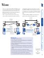
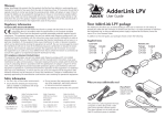
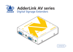
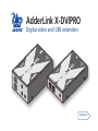
AdderLink X-DVIPRO Digital video and USB extenders Further information Troubleshooting.........................................................................11 Getting assistance.......................................................................11 Warranty.....................................................................................12 Safety information.....................................................................12 Radio Frequency Energy............................................................13 Connections..................................................................................5 Mounting the modules – desk or rack....................................5 Connections at the local module............................................6 Power connection...............................................................7 Connections at the remote module........................................8 Power connection...............................................................9 Installation Operation....................................................................................10 General use............................................................................10 Video display (EDID) information.........................................10 HDMI 1.3a operation.............................................................10 Power and activity indicators................................................10 Introduction..................................................................................2 What’s in the box.........................................................................3 What you may additionally need................................................4 Operation F Welcome Contents 1 CAT7a - 50m max CAT6 - 45m max CAT5e - 35m max Additional CATx link on MS2 variants X-DVIPRO link with direct cable connection Additional video channel and dual stereo audio channels on MS2 variants X-DVIPRO Local Patch lead <2m max Patch lead <2m max X-DVIPRO Remote Patch panel Patch panel Additional CATx link on MS2 variants X-DVIPRO Remote X-DVIPRO Local X-DVIPRO link with cable and patch panel connections Additional video channel and dual stereo audio channels on MS2 variants CAT7a - 60m max CAT6 - 55m max CAT5e - 45m max extending digital video signals. Using our proprietary transmission techniques the X-DVIPRO and X-DVIPRO-MS2 modules can reliably transfer video rates up to 165 Mpixels per second. This is in addition to two USB channels for keyboard and mouse - all via the same single length of Category 5e, 6 or 7a twisted pair cabling. The AdderLink X-DVIPRO and X-DVIPRO-MS2 extender modules have been designed to be quick to install and totally transparent in operation. Cable distance rules • Extension distances up to 60m are supported. • Extensions of 60m may be achieved with single uninterrupted runs of recommended cable (Adder CAT7a patch cable) at full resolution. • Extensions of 55m may be achieved with single uninterrupted runs of CAT6 bulk/trunk (not patch) cable at full resolution. • Adder does not recommend CAT5e cables for use with this product. However, 45m may be typically achieved with single uninterrupted runs of CAT5e bulk/trunk (not patch) cables at full resolution. • Overall cable runs must be reduced by 5m for each additional cable coupling. • Run specifications may be increased by 10m when using resolutions of 1280 x 1024 or lower. • All patch cables should be as short as possible and should be no longer than 2m. • It is recommended that Adder CAT7a patch cables are used for maximum performance. Recommended 50m link cable for best results: Adder part number: VSCAT7-50 F Thank you for choosing the AdderLink X-DVIPRO or X-DVIPRO-MS2 extenders. These compact modules present the quickest way to extend high quality DVI digital video plus USB keyboard and mouse (plus on MS2 variants, a second digital video channels and two stereo audio channels) with an additional two USB peripherals up to 60 metres away from your computer. Thanks to our long involvement and investment in extender technology we have succeeded in overcoming the numerous problems associated with Welcome 2 What’s in the box Additional 12.5W power adapter and country- specific power lead Local module Remote module AdderLink X-DVIPRO standard modules Video cable DVI/D to DVI/D USB cable 2m (type A to B) Eight self-adhesive rubber feet CD-ROM The MS2 variant package includes all of the above ancillary items plus: Local module Remote module Additional USB cable 2m (type A to B) Additional video cable DVI/D to DVI/D 3.5mm jack to jack stereo audio cable F AdderLink X-DVIPRO-MS2 dual video/audio modules 3 What you may additionally need Power adapter and countryspecific power lead for X-DVIPRO local module, if powering via the USB port is not possible. In such cases, two power adapters are required for X-DVIPRO-MS2 local modules. Part number: PSU-IEC-5VDC-2.5A Rack mount kit for X-DVIPRO Part number: X-RMK-FASCIA Rack mount chassis Part number: X-RMK-CHASSIS Extra 3.5mm jack to jack stereo audio cable Part number: VSC22 50 metre CAT7 link cable Part number: VSCAT7-50 F Rack mount kit for X-DVIPRO-MS2 Part number: X-RMK-FASCIA-DUAL HDMI to DVI-D video cable Part number: VSCD11 4 Installation Desk mount Apply the supplied self-adhesive rubber feet to the underside of the module. The X-DVIPRO and X-DVIPRO-MS2 modules can be situated on a desk or alternatively, for larger installations, mounted within an optional rack mount chassis. Mounting the modules – desk or rack Rack mount 1 Place the rack securing plate (available as a separate kit) onto the front of the module and secure it with the two countersunk screws. 2 Orient the X-DVIPRO (or X-DVIPRO-MS2) module on its side so that its labelled face is the correct way up. 3 Slide the module into the required rack position. The rectangular cut-out in the front upper lip of the rack allows the two screws on the module’s upper edge to slide through. 4 The rack mount chassis has a series of holes in its floor that are spaced to accommodate the two screws on the module’s lower edge. Ensure that the screws correctly locate into the two holes of the chosen slot. The rack securing plate on the module should now be flush with the front of the rack mount chassis. 5 Use the third (pan-head) screw, in the top hole of the rack securing plate to fasten the module to the rack. F Installation of the X-DVIPRO and X-DVIPRO-MS2 modules is straightforward and requires minimal configuration in most cases. • Connections at the local module • Connections at the remote module Note: After all connections are made, power up the monitor and the REMOTE module first (followed by the LOCAL module, if using the X-DVIPRO-MS2 variant) and then switch on the computer. Connections 5 Connections at the local module 3 Use the supplied USB cable to link the USB socket of the local module to a vacant USB socket on the computer. Note: Do not use USB cables longer than 3 metres to connect the local module to the computer. 1 Where possible, ensure that power is disconnected from the computer system to be connected. 2 Use the supplied DVI/D link cable to connect the DVI input socket of the local module to the digital video output socket of the computer. To USB port [MS2 variant only] Optionally attach a second USB connection from the computer system using the supplied USB cable. To second USB port To first USB port [MS2 variant only] Optionally link one or two stereo audio inputs to the module using 3.5mm audio cable(s). One 3.5mm audio cable is supplied with MS2 variant packages. To secondary video output port To primary video output port Feeds the LOWER two USB sockets on the remote unit [MS2 variant only] Optionally attach a second video input from the computer system using the supplied DVI/D link cable. Feeds the UPPER two USB sockets on the remote unit F To video output port To secondary audio port To primary audio port 6 4 Connect the link cable (see page 2 for cable advice) to the local module socket labelled TO REMOTE. Power connection The X-DVIPRO local module is designed to derive its power from the host computer via the USB connection (two USB connections in the case of the MS version). If this is not possible, then you will need to use one or two optional Adder power adapter(s). Optionally for X-DVIPRO and X-DVIPRO-MS2 units: 1 Connect the output lead of the optional power adapter(s) to the socket(s) labelled ‘POWER‘ on the local module. Primary CATx link cable Note: After all connections are made, power up the monitor and the REMOTE module first (followed by the LOCAL module, if using the X-DVIPRO-MS2 variant with power adapters) and then switch on the computer. Secondary CATx link cable X-DVIPRO: Use an optional power adapter only if powering from the host (via USB) is not possible. X-DVIPRO-MS2: Use two optional power adapters if powering from the host (via dual USB connections) is not possible. Do not use squid cables or power splitters. Two separate power adapters must be used. 2 Insert the IEC connector of the separate power lead(s) into the corresponding socket(s) of the power adapter(s). Connect the other end of the power lead(s) to one/two nearby mains socket(s). F [MS2 variant only] Attach a second category 5e, 6 or 7a link cable (up to 60 metres in length) to the upper socket on the MS2 local module. CATx link cable 7 Connections at the remote module To keyboard, mouse and other USB peripherals IMPORTANT: The total current that may be drawn from the USB ports is 1.2A, which should be sufficient for a keyboard, mouse (no more than 100mA each) and any two other devices (500mA maximum each). If more power for USB devices is required, please use a powered USB hub. Fed from the UPPER USB socket on the local unit To keyboard, mouse and other USB peripherals To secondary video monitor To primary video monitor [MS2 variant only] Optionally attach a second DVI video monitor. [MS2 variant] Connect the leads from the keyboard and mouse to the two USB sockets on the remote module. [MS2 variant only] Optionally connect one or two sets of stereo speakers to the module. One 3.5mm audio cable is supplied with MS2 variant packages. Fed from the LOWER USB socket on the local unit To video monitor 3 Connect the leads from the keyboard and mouse to the two USB sockets on the remote module. Note: On the single head variant, it is not important which of the four sockets are used. F 1 Place the remote module adjacent to the user location. 2 Connect the DVI/D lead from the video monitor to the DVI output socket of the remote module. To secondary speakers To primary speakers 8 Power connection 1 Connect the output lead of the supplied power adapter to the socket labelled ‘POWER‘ on the remote module. 4 Connect the link cable (see page 2 for cable advice) to the remote module socket labelled TO LOCAL. X-DVIPRO: Output lead from the power adapter Primary CATx link cable X-DVIPRO-MS2: Output lead from the power adapter 2 Insert the IEC connector of the separate power lead into the corresponding socket of the power adapter. Connect the other end of the power lead to a nearby mains socket. 3 After all connections are made, power up the monitor and remote module (then the local module, if using the X-DVIPRO-MS2 variant) and finally switch on the computer. F Secondary CATx link cable [MS2 variant only] Attach a second category 5e, 6 or 7a link cable (up to 60 metres in length) to the upper socket on the MS2 remote module. CATx link cable 9 Operation HDMI 1.3a operation Using optional HDMI to DVI converter cables (Adder part number: VSCD11), the AdderLink X-DVIPRO-MS can support HDMI video and audio up to the 165MHz clock rate (1920 x 1080 at 60Hz, 24-bit colour). Eight channels of HDMI audio are supported with sample sizes of 16, 20 or 24-bits at 32KHz, 44.1kHz, 48kHz, 88.2kHz, 96kHz, 176.4kHz, or 192kHz (simultaneously with the jack audio). Note: The High-bandwidth Digital Content Protection (HDCP) and Consumer Electronics Control (CEC) schemes are not supported. Local module Green: • On when power is present. Yellow: • On when a valid DVI video input signal is being received from the computer. • Off when the CATx link cable is disconnected. Note: On MS2 variants, the link ports are independent, so failure of one link does not affect the video or USB status of the other link. Remote module Green: • On when power is present. Yellow: • On when a valid DVI video input signal is being received from the local module. Flashes regularly (twice per second) when no valid DVI video signal is being received from the local module. Note: On MS2 variants, the link ports are independent, so failure of one link does not affect the video or USB status of the other link. Extended Display Identification Data (or EDID) is an industry standard scheme which allows video displays to declare their capabilities to the computer’s video adapter circuitry, allowing the latter to optimise their outputs accordingly. Since the widespread adoption of the scheme, video adapters have become increasingly dependent on receiving relevant EDID information during start-up, before they will output anything more than a rudimentary video signal. Each time that the remote module is powered on, it attempts to read the EDID information from the connected DVI video monitor. If the attempt is successful, the information is transferred to the local module and stored within non-volatile memory. This information is then made available to the computer’s video adapter when required. On MS2 variants, EDID is handled independently for the two video connections, allowing completely different video display configurations on the two ports. Each module provides two indicators to confirm power status and also feedback about the various input signals: Video display (EDID) information Power and activity indicators operation In use, the X-DVIPRO and X-DVIPRO-MS2 modules should be transparent - the system and its peripherals should operate exactly as normal, the only difference being that they are now up to 60 metres apart. F General use Operation 10 Further information • Email – [email protected] • Fax in the UK: in the US: 01954 780081 +1 888 275 1117 • Phone in the UK: in the US: 01954 780044 +1 888 275 3337 • Adder Technology website – www.adder.com Check the Support section of our website for the latest solutions and driver files. No video image is displayed on the remote monitor • Check the yellow indicators on the local and remote modules while no keys are pressed on the keyboard and no mouse movements are being made both indicators should be continually on when a valid video signal is present. LOCAL: If the yellow indicator is giving a regular flash (twice per second), then the video feed to the local module is not valid. Try connecting a DVI monitor (preferably using the same DVI link cable as used with the local module) directly to the computer and check for a correct image. REMOTE: If the yellow indicator is giving a regular flash (twice per second), then the video feed via the link cable is not valid. If the link cable is long, try using a short link cable temporarily to check for basic operation. If the yellow indicators are off, then the link cable is not properly connected. If you are still experiencing problems after checking the list of solutions in the Troubleshooting section then we provide a number of other solutions: If you experience problems when installing or using the X-DVIPRO/X-DVIPROMS2 modules, please check through this section for a possible solution. If your problem is not listed here and you cannot resolve the issue, then please refer to the ‘Getting assistance’ section. Getting assistance Troubleshooting 11 • For use in dry, oil free indoor environments only. • Do not use to link between buildings. • Ensure that the twisted pair interconnect cable is installed in compliance with all applicable wiring regulations. • Do not connect the CATx link interface (RJ45 style connector) to any other equipment, particularly network or telecommunications equipment. • Warning – the power adapter contains live parts. • No user serviceable parts are contained within the power adapter - do not dismantle. • Plug the power adapter into an earthed socket outlet close to the unit that it is powering. • Replace the power adapter with a manufacturer approved type only. • Do not use the power adapter if the power adapter case becomes damaged, cracked or broken or if you suspect that it is not operating properly. • If you use a power extension cord with the units, make sure the total ampere rating of the devices plugged into the extension cord do not exceed the cord’s ampere rating. Also, make sure that the total ampere rating of all the devices plugged into the wall outlet does not exceed the wall outlet’s ampere rating. • Do not attempt to service the units yourself. • The units and power supplies can get warm in operation – do not situate them in an enclosed space without any ventilation. • The units do not provide ground isolation and should not be used for any applications that require ground isolation or galvanic isolation. Adder Technology Ltd warrants that this product shall be free from defects in workmanship and materials for a period of two years from the date of original purchase. If the product should fail to operate correctly in normal use during the warranty period, Adder will replace or repair it free of charge. No liability can be accepted for damage due to misuse or circumstances outside Adder’s control. Also Adder will not be responsible for any loss, damage or injury arising directly or indirectly from the use of this product. Adder’s total liability under the terms of this warranty shall in all circumstances be limited to the replacement value of this product. If any difficulty is experienced in the installation or use of this product that you are unable to resolve, please contact your supplier. Safety information Warranty 12 Canadian Department of Communications RFI statement This equipment does not exceed the class A limits for radio noise emissions from digital apparatus set out in the radio interference regulations of the Canadian Department of Communications. Le présent appareil numérique n’émet pas de bruits radioélectriques dépassant les limites applicables aux appareils numériques de la classe A prescrites dans le règlement sur le brouillage radioélectriques publié par le ministère des Communications du Canada. This equipment generates, uses and can radiate radio frequency energy and if not installed and used properly, that is, in strict accordance with the manufacturer’s instructions, may cause interference to radio communication. It has been tested and found to comply with the limits for a class A computing device in accordance with the specifications in Subpart J of part 15 of FCC rules, which are designed to provide reasonable protection against such interference when the equipment is operated in a commercial environment. Operation of this equipment in a residential area may cause interference, in which case the user at his own expense will be required to take whatever measures may be necessary to correct the interference. Changes or modifications not expressly approved by the manufacturer could void the user’s authority to operate the equipment. This equipment has been tested and found to comply with the limits for a class A computing device in accordance with the specifications in the European standard EN55022. These limits are designed to provide reasonable protection against harmful interference. This equipment generates, uses and can radiate radio frequency energy and if not installed and used in accordance with the instructions may cause harmful interference to radio or television reception. However, there is no guarantee that harmful interference will not occur in a particular installation. If this equipment does cause interference to radio or television reception, which can be determined by turning the equipment on and off, the user is encouraged to correct the interference with one or more of the following measures: (a) Reorient or relocate the receiving antenna. (b) Increase the separation between the equipment and the receiver. (c) Connect the equipment to an outlet on a circuit different from that to which the receiver is connected. (d) Consult the supplier or an experienced radio/TV technician for help. FCC Compliance Statement (United States) European EMC directive 2004/108/EC A Category 5 (or better) shielded twisted pair cable must be used to connect the local and remote units in order to maintain compliance with radio frequency energy emission regulations and ensure a suitably high level of immunity to electromagnetic disturbances. All other interface cables used with this equipment must be shielded in order to maintain compliance with radio frequency energy emission regulations and ensure a suitably high level of immunity to electromagnetic disturbances. Radio Frequency Energy 13 Tel: +65 6288 5767 Fax: +65 6284 1150 Adder Asia Pacific 6 New Industrial Road, Hoe Huat Industrial Building #07-01, Singapore 536199 Adder Corporation, 350R Merrimac Street, Newburyport, MA 01950, United States of America Tel: +1-888-932-3337 Fax: +1-888-275-1117 Adder Technology Limited, Unit 5, Saxon Way, Bar Hill, Cambridge, CB23 8SL, United Kingdom Tel: +44 (0)1954 780044 Fax: +44 (0)1954 780081 © 2011 Adder Technology Limited All trademarks are acknowledged. Release 2.0d November 2011 Part No. MAN-X-DVIPRO Documentation by: www.ctxd.com 14