1
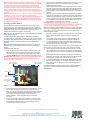
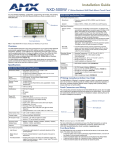
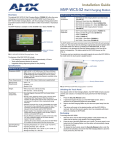
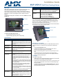
Installation Guide MVP-WDS-9 Wall/Flush Docking Station Overview MVP-WDS-9 Specifications (Cont.) While charging the MVP-9000i, the Power-over-Ethernet MVP-WDS-9 Wall/ Flush Mount Docking Station provides fast, reliable wired Ethernet communication to the touch panel. In addition, the MVP-WDS-9 employs a unique, anti-theft locking mechanism to keep the touch panel safe and secure. With a push of a button, the panel glides forward for simple removal and transport. Included Accessories • Snap-On Ferrite (04-0007) • MVP-WDS-9 Wall Docking Station Template (68-5967-01) • PS-POE-AT High Power PoE Injector (FG423-81) Other AMX Equipment: • • • • • The Wall/Flush Docking Station is available in either white (FG5967-13) or black (FG5967-12). MVP-WDS-9 MVP-9000i-GB MVP-9000i-GB, Black (FG5967-01) MVP-9000i-GW, White (FG5967-02) MVP-TDS-9-GB, Black (FG5967-10) MVP-TDS-9-GW, White (FG5967-11) CB-MVP-WDS9 Rough-In Box (FG038-13) The MVP-9000i panel remains locked in the MVP-WDS-9 until unlocked by the user. This may be done by pressing the Security Release button and then entering an appropriate password (please refer to the MVP-9000i Operation/ Reference Guide, available from www.amx.com, for more information). The station ejects the MVP-9000i device top first (FIG. 2). The device uses two neodymium rare-earth magnets to secure the MVP-9000i to the cradle when the touch panel is angled forward. Wall Docking Station Security Release button MVP-9000i FIG. 1 MVP-WDS-9-GB Wall Docking Station - Front The features of the MVP-WDS-9 include: • • Touch panel password feature for security Integrated docking alignment guides for easy docking Specifications Security Release button MVP-WDS-9 Specifications Dimensions (HWD): • 9.75" x 12.50" x 2.13" (24.77cm x 31.75cm x 5.40cm) Note: Always use the cutout/installation dimensions for the MVP-WDS-9 when installing this unit into various surfaces. A cutout template is included with the device for ease of installation. FIG. 2 MVP-WDS-9-GB Wall Docking Station - Side View Unlocking the Touch Panel Once placed within the Wall Docking Station, the MVP-9000i remains secured until the user unlocks it. To release the touch panel from the Wall Docking Station: Power Requirements: • 30 W (Class II listed power supplemented), supplied via the PS-POE-AT High-Power PoE Injector. Startup Power Requirements: • Cradle and panel (not charging): 16 W • Cradle and panel (charging): 23 W • Ejection: 23 W 1. 2. Weight: • Without back box: 1.50 lbs (0.68 kg) • With back box: 2.40 lbs (1.09 kg) 3. Front Panel Components: • Securing Magnets: Secures MVP touch panel during ejection. • Security Latch: Adds the primary layer of security when mounting an MVP touch panel. When the device is inserted, this latch grabs onto the rear of the touch panel and secures it to prevent it from inadvertently being removed. • Interface Connector: A set of contacts that connect to the underside MVP connector strip. This connection provides both communication and power between the touch panel and the MVP-WDS-9. • Support Cradle: This retractable mechanism supports a resting MVP panel and allows a user to either insert or remove a connected MVP panel. • Security Release pushbutton: Located on the front of the unit, this pushbutton toggles an on-screen security keypad if security is enabled. - Entering the correct release code allows the MVP-WDS-9 to release the touch panel from the security latch. Operating/Storage Environments: • Operating Temperature: 0° C (32° F) to 40° C (104° F) • Battery Charging Temperature: 0° C (32° F) to 30° C (86° F) • Operating & Battery Charging Humidity: 20% to 85% RH • Storage Temperature: -10° C (-14° F) to 60° C (140° F) • Storage Humidity: 5% - 85% RH 4. Press the Security Release button. A password keypad will pop up on the MVP-9000i screen. Enter a password in the password keypad and press Enter. Wait for the Wall Docking Station to pivot the touch panel away from the wall. The device will remain in the ejected position until the MVP-9000i is removed. Wait until the device’s ejection door has completely withdrawn before re-installing the MVP-9000i. Recharging To recharge the MVP-9000i: 1. 2. 3. Slide the device into the Wall Docking Station cradle bottom-first and make sure the device is fully seated in the Docking Station. Press the top of the MVP-9000i back until it clicks. The touch panel is now locked into the Docking Station, and the station will automatically charge the device’s battery. To release the touch panel, press the Security Release button, enter the password (if activated), and wait for the Wall Docking Station to pivot the touch panel away from the wall. Note: Charging Lithium Polymer batteries at high temperature will reduce the battery life. Industry guidelines dictate that batteries should not be charged at temperatures above 45° C (113° F). The temperature is determined by a combination of the ambient temperature where the panel is located, plus temperature increases normally occurring inside electronic devices containing batteries. AMX has implemented battery temperature monitoring features to maximize the rate of battery charging, while staying within industry temperature guidelines. 4. Battery charge times will increase in installations where the room temperature is above 25° C (77° F), and may be temporarily suspended at room temperatures above 30° C (86° F). Battery charging will automatically resume once the temperature has fallen to appropriate levels. Minimizing the display backlight intensity and turning off the backlight during periods of non-use will also yield faster charge times. 6. Installing the MVP-WDS-9 WARNING: Make absolutely certain that the back box is in its intended position. Once the back box lockdown wings are extended, removing the back box will be extremely difficult without damaging the wall in the process. Since the Wall Docking Station is intended to be affixed to a wall or other permanent structure, care must be taken to ensure its proper installation to prevent potential damage to the MVP-9000i placed within. The device may be installed into existing walls, but the optional metal rough-in box must be installed before installation of drywall or other paneling. Note: Other than wall installation tools, the only tool required for this installation is a #2 Phillips screwdriver. 5. Note: The maximum recommended torque to screw in the wings on the plastic back box is 5 IN-IBS [5(NI-CM)]. Applying excessive torque while tightening the wing screws, such as with powered screwdrivers, can strip out the wings or damage the plastic back box. 7. Installing the Wall Docking Station and Plastic Back Box The Plastic Back Box has two pairs of knockouts at the top of the box and four (4) lockdown wings attached to the box with Phillips-head screws. For ease of installation, the interior of the box contains an “UP” arrow pointing to the knockouts. Run the Ethernet cable through the knockout into the back box. Pull out about six inches (15.25cm) of cable into the back box to facilitate installation of the MVP-WDS-9. Slide the plastic back box into the hole, being careful not to twist or pinch the cable, and set it flush with the wall. Make sure that all of the lockdown wings are folded into their slots before attempting to insert the box. For ease of installation, the inside of the box has the direction "UP" labeled for reference. Extend the wings on the sides of the back box by tightening the screws inside the box, taking care not to overtighten. Not all of the wings must be extended to lock the back box in place, but extending a minimum of two wings on opposite sides of the box is required. Apply enough pressure to the screw head to keep the box flush with the wall: this ensures that the wing will tighten up against the inside of the wall. 8. 9. Attach the included snap-on ferrite to the Ethernet cable, as close to the RJ-45 connector as possible. Attach the cable to the Ethernet Port (FIG. 3). Firmly seat the device against the back box. Make sure that the tab connectors at the bottom of the device are locked into the back box. Insert the two installation screws from the MVP-WDS-9 Installation Kit into the screw holes in the interior compartment of the device and tighten them to anchor the device to the back box. Note: The optional CB-MVP-WDS9 Metal Rough-In Box is not required for installation of the supplied Plastic Back Box, but it offers an extra level of support. Note: For ease of installation, put each screw on a neodymium magnet in the device’s interior compartment to keep them on hand until they are needed. To install the Plastic Back Box: 10. 1. Cut a hole into the wall or surface intended to hold the back box. The back box is sized 12 1/16 inches (30.64 cm) long and 8 11/16 inches (22.07 cm) high. Use the included MVP-WDS-9 Wall Docking Station Template (68-5967-01) as an aid for hole placement and measurement. WARNING: Make sure to measure the size of the intended hole before starting to cut it. Cutting the hole slightly smaller than the dimensions to allow for adjustments is highly recommended. Recommended Ethernet installation Knockout placement in back box Recommended USB installation 11. 12. Take a rubber pad and remove its adhesive backing. Put the foot, adhesive-side down, in the slot surrounding the screw hole in the Wall Docking Station. Press down firmly to remove any air bubbles from underneath the foot. Install an MVP-9000i device by placing it into the interior compartment bottom-first. Press the top of the touch panel until it is flush with the Wall Docking Station. The neodymium magnets will hold it in place. To remove the MVP-9000i, press the Security Release button and wait for the touch panel to pull away from the Wall Docking Station. Once it has been released, grip it by the top of the device, and pull it free from the Docking Station. For additional installation information, please refer to the MVP-9000i Modero ViewPoint Touch Panel Operation/Reference Guide, available online at www.amx.com. Ethernet port Ferrite installation position Recommended Ethernet cable path FIG. 3 Back of MVP-WDS-9 Wall Docking Station 2. 3. Select the knockout to be removed from the top of the back box. The box has two pairs of knockouts, at the top left and the top right (FIG. 3). Note: To assist with wiring, and to avoid mechanical stresses on the wire and the mechanism of the Wall Docking Station, the top left knockout, when viewing the device from the rear, is preferred for use for Ethernet installation. Use the top right knockout for USB cable connection. Connect the PS-POE-AT High-Power PoE Injector to a power source. Connect the PS-POE-AT to an Ethernet switch on the network via one length of Ethernet cable and insert one length of Ethernet cable for connection to the Wall Docking Station. For full warranty information, refer to the AMX Instruction Manual(s) associated with your Product(s). 11/11 ©2011 AMX. All rights reserved. AMX and the AMX logo are registered trademarks of AMX. AMX reserves the right to alter specifications without notice at any time. 3000 RESEARCH DRIVE, RICHARDSON, TX 75082 • 800.222.0193 • fax 469.624.7153 • technical support 800.932.6993 • www.amx.com 93-5967-12 REV: E