1
Installation and Assembly:
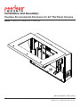
Peerless Environmental Enclosure for 42" Flat Panel Screens
Model: FPE42F-S, FPE42FH-S, FPE42F-B
Max Load Capacity: 250 lb (113 kg)
2300 White Oak Circle • Aurora, IL 60502 • (800) 865-2112 • Fax: (800) 359-6500 • www.peerlessmounts.com
ISSUED: 07-16-10 SHEET #: 061-9050-4 03-04-11
NOTE: Read entire instruction sheet before you start installation and assembly.
WARNING
• Do not begin to install your Peerless product until you have read and understood the instructions and warnings
contained in this Installation Sheet. If you have any questions regarding any of the instructions or warnings, for US
customers please call Peerless customer care at 1-800-865-2112, for all international customers, please contact
your local distributor.
• Due to outdoor environmental conditions such as strong wind gusts, heavy snow, hail, rain, etc. The environmental
enclosure and hardware, must be inspected at least once a year, and immediately following any time winds exceed
90 mph. A qualified installer or inspector must check for signs of rust, loose fasteners, bent metal, etc. If evidence
of excessive wear, deterioration or any unsafe condition is observed, this product must be taken out of service
immediately. Direct all inquiries to customer care if you have any questions.
• Glass face of enclosure must avoid direct sunlight or damage to display may occur.
• This product should only be installed by someone of good mechanical aptitude, has experience with basic building
construction, and fully understands these instructions.
• Make sure that the supporting surface will safely support the combined load of the equipment and all attached
hardware and components.
• Never exceed the Maximum Load Capacity. See page one.
• If mounting to wood wall studs, make sure that mounting screws are anchored into the center of the studs. Use of
an "edge to edge" stud finder is highly recommended.
• Always use an assistant or mechanical lifting equipment to safely lift and position equipment.
• Tighten screws firmly, but do not overtighten. Overtightening can damage the items, greatly reducing their holding
power.
• This product was designed for use with other outdoor products only
• This product was designed to be installed on the following wall construction only;
WALL CONSTRUCTION
HARDWARE REQUIRED
•
•
•
•
•
•
Included
Included
Contact Qualified Professional
Contact Qualified Professional
Contact Qualified Professional
Contact Qualified Professional
Wood Stud
Wood Beam
Solid Concrete
Cinder Block
Brick
Other or unsure?
Tools Needed for Assembly
• stud finder ("edge to edge" stud finder is
recommended)
• drill
• phillips screwdriver, 5 mm allen wrench,
flathead screwdriver
• 5/32" (4 mm) bit for wood stud wall
• level
• hammer
Table of Contents
Parts List ............................................................................................................................................................................... 3
Removing bay door ............................................................................................................................................................... 5
Wall installation .......................................................................................................................................................................7
Wall plate installation ............................................................................................................................................................. 8
Reinstalling door ....................................................................................................................................................................9
Attaching vertical brackets to screen ............................................................................................................................. 10,11
Mounting and removing screen ........................................................................................................................................... 12
Depth Adjustment ................................................................................................................................................................ 14
Setting Thermotstat ............................................................................................................................................................. 15
Filter Replacement .............................................................................................................................................................. 17
2 of 18
ISSUED: 07-16-10 SHEET #: 061-9050-4 03-04-11
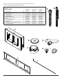
Before you begin, make sure all parts shown are included with your product.
Parts may appear slightly different than illustrated.
A
B
C
E
F
G
H
I
J
K
L
B
C
Parts List
Description
enclosure assembly
adapter brackets
wood screws
sealed washer
ROXTEC cable seal
key
12 mm flat head screw
serrated locknut
wall plate
cord cover plate assembly (not shown)
4 mm allen wrench
Qty.
1
2
6
6
1
1
4
4
1
2
1
FPE42F-S
Part #
061-7246
201-P1513
5S1-015-C03
540-4067
600-0107
600-0116
520-2325
530-2021
201-P1018
061-7285
560-1727
FPE42FH-S
Part #
061-7304
201-P1513
5S1-015-C03
540-4067
600-0107
600-0116
520-2325
530-2021
201-P1018
061-7285
560-1727
FPE42F-B
Part #
061-T1246
201-P1513
5S1-015-C03
540-4067
600-0107
600-0116
520-2325
530-2021
201-P1018
061-T1285
560-1727
A
E
G
F
H
I
J
L
3 of 18
ISSUED: 07-16-10 SHEET #: 061-9050-4 03-04-11
Adapter Bracket Fasteners
M4 x 12 mm (4)
(504-9013)
M5 x 12 mm (4)
(520-1027)
M4 x 25 mm (4)
(504-1015)
M5 x 25 mm (4)
(520-9543)
M6 x 12 mm (4)
(520-1128)
M6 x 20 mm (4)
M6 x 30 mm (4)
(520-9402)
(510-9109)
.5" spacer (4)
(540-1057)
M6 x 25 mm (4)
(520-1208)
.75" spacer (4)
(540-1059)
M8 x 40 mm (4)
(520-1136)
M8 x 16 mm (6)
(520-9257)
4 of 18
multi-washer (4)
(580-1036)
M8 x 25 mm (4)
(520-1031)
ISSUED: 07-16-10 SHEET #: 061-9050-4 03-04-11
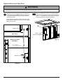
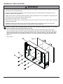
Optional Removal of Bay Door
WARNING
• Grasp bay door firmly. Bay door will swing freely when gas springs are removed.
1
Bay door may be removed for ease of installation
to mounting surface. NOTE: Removal of bay door
is optional. Installation may be completed without
removing bay door.
1-1
Remove center set of 10-24 x .5" phillips screws
from inside of enclosure assembly (A) as shown in
figure 1.1. Slide bay door to the right to disengage
hinges and lift off of enclosure assembly.
Insert flathead screwdriver under brass clip of gas
spring shown in detail 1 and pry up. Pull gas spring
away from bay door.
A
BRASS CLIP
BAY DOOR
10-24 x .5"
PHILLIPS SCREWS
MAIN ENCLOSURE
ASSEMBLY
fig. 1.1
GAS SPRING
BRASS CLIP
DETAIL 1
5 of 18
ISSUED: 07-16-10 SHEET #: 061-9050-4 03-04-11
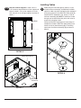
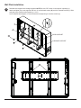
Installing Cables
1-2
Removal of Rear Supports: Loosen 1/4-20 x
2.36" screws at top and bottom of rear supports as
shown in detail 2. Lift up rear supports, tilt to the
side, and pull out of carriage supports as shown in
detail 3.
2
1/4-20 SCREWS
Cables may be routed through top, bottom, or rear
of main enclosure assembly. An additional available
option for cable entry while maintaining the waterproof
seal of the enclosure is the ROXTEC cable gland (F).
Install ROXTEC hardware to top, bottom, or rear of
enclosure assembly (A). NOTE: If cables are routed
through rear enclosure assembly hole, wall mount is
required for mounting to wall.
Follow the ROXTEC manufacturers' instructions for
installation included in ROXTEC cable gland (F) box.
Install cord cover plate assembly (K) to remaining
open holes of enclosure assembly (A) as shown in
detail 4.
REAR SUPPORTS
1/4-20 SCREWS
DETAIL 2
A
REAR SUPPORTS
K
DETAIL 4
CARRIAGE
SUPPORTS
DETAIL 3
6 of 18
ISSUED: 07-16-10 SHEET #: 061-9050-4 03-04-11
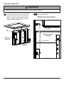
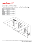
Installation to Wood Stud Wall
WARNING
• DO NOT lift more weight than you can handle. Always use an assistant or mechanical lifting equipment to safely lift
and position enclosure assembly (A).
• Installer must verify that the supporting surface will safely support the combined load of the equipment and all
attached hardware and components.
• Tighten wood screws so that the enclosure assembly is firmly attached, but do not overtighten. Overtightening can
damage the screws, greatly reducing their holding power.
• Never tighten in excess of 80 in. • lbs. (9 N.M.).
• Make sure that mounting screws are anchored into the center of the stud. The use of an "edge to edge" stud finder
is highly recommended.
• Hardware provided is for attachment of mount through standard thickness drywall or plaster into wood studs.
Installers are responsible to provide hardware for other types of mounting situations.
3
NOTE: This step is for mounting enclosure assembly (A) flush against supporting surface. For use with
mount, follow instructions provided with wall mount.
Use a stud finder to locate the edges of the studs and draw a vertical line down each stud’s center. Place
enclosure assembly (A) on wall as a template, level and mark the center of the six mounting holes. Make sure
that the mounting holes are on the stud centerlines. Drill six 5/32" (4 mm) dia. holes 2.5" (64 mm) deep. Make
sure that the enclosure is level and secure it using six 2.5" wood screws (C) and six washers (E) as shown in
figure 3.1.
Skip to step 4.
A
fig. 3.1
E
C
7 of 18
ISSUED: 07-16-10 SHEET #: 061-9050-4 03-04-11
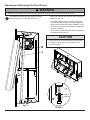
Wall Plate Installation
4
Reinstall rear supports into carriage supports. NOTE: Be sure "UP" arrow of rear support is pointing up.
Attach wall plate (J) to rear supports with four 12 mm flat head screws (H) and four serrated locknuts (I). Slide
wall plate (J) to desired vertical position (+/- 3/4").
Level wall plate and retighten 12 mm flat head screws (H) using 4 mm allen wrench (L).
I
J
REAR SUPPORT
H
CARRIAGE SUPPORT
H
8 of 18
ISSUED: 07-16-10 SHEET #: 061-9050-4 03-04-11
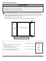
Reinstalling Bay Door
WARNING
• Grasp bay door firmly. Bay door will swing freely when gas springs are removed.
5
If bay door was removed in step 1, lower bay door
onto enclosure assembly and slide to the left to
engage hinges. Align holes of center hinge with
holes of enclosure assembly (A). Reinstall two
10-24 x .5" phillips screws to inside of enclosure
assembly as shown in figure 5.1.
5-1
Secure both gas springs to bay door by pressing
on as shown in detail 5.
NOTE: Be sure thin end of gas spring is
attached to main enclosure assembly.
BAY DOOR
A
MAIN ENCLOSURE
ASSEMBLY
10-24 x .5"
PHILLIPS
SCREWS
GAS SPRING
fig. 5.1
DETAIL 5
9 of 18
ISSUED: 07-16-10 SHEET #: 061-9050-4 03-04-11
Installing Adapter Brackets
WARNING
• Tighten screws so adapter brackets are firmly attached. Do not tighten with excessive force. Overtightening can cause
stress damage to screws, greatly reducing their holding power and possibly causing screw heads to become detached. Tighten to 40 in. • lb (4.5 N.M.) maximum torque.
• If screws don't get three complete turns in the screen inserts or if screws bottom out and bracket is still not tightly
secured, damage may occur to screen or product may fail.
6
To prevent scratching the screen, set a cloth on a flat, level surface that will support the weight of the screen.
Place screen face side down. If screen has knobs on the back, remove them to allow the adapter brackets to be
attached. Place adapter brackets (B) on back of screen, align to holes, and center on back of screen as shown
below. Attach the adapter brackets to the back of the screen using the appropriate combination of screws, multiwashers and spacers as shown in steps 6-1 and 6-2.
NOTE: Top and bottom holes must always be used.
Verify that all holes are properly aligned, and then tighten screws using a phillips screwdriver.
X
B
CENTER BRACKETS VERTICALLY
ON BACK OF SCREEN
NOTE: "X" dimensions should be equal.
X
MULTI-WASHER
Notes:
MEDIUM HOLE FOR M5 SCREWS
• The number of fasteners used will vary, depending
upon the type of screen.
• Multi-washers and spacers may not be used,
depending upon the type of screen.
SMALL HOLE FOR M4 SCREWS
• Use the corresponding hole in the multi-washer
that matches your screw size as shown.
LARGE HOLE FOR M6 SCREWS
10 of 18
ISSUED: 07-16-10 SHEET #: 061-9050-4 03-04-11
For Flat Back Screen
6-1
Begin with the shortest length screw, hand thread through multi-washer and adapter bracket into screen as
shown below. Screw must make at least three full turns into the mounting hole and fit snug into place. Do not
over tighten. If screw cannot make three full turns into the screen, select a longer length screw from the baffled
fastener pack. Repeat for remaining mounting holes, level brackets and tighten screws.
NOTE: Spacers may not be used, depending upon the type of screen.
SCREEN
MULTI-WASHER
SCREW
ADAPTER BRACKET (B)
If you have any questions, please call Peerless customer care at 1-800-865-2112.
For Bump-out or Recessed Back Screen
6-2 Begin with longer length screw, hand thread through multi-washer, adapter bracket and spacer in that order into
screen as shown below. Screw must make at least three full turns into the mounting hole and fit snug into place.
Do not over tighten. If screw cannot make three full turns into the screen, select a longer length screw from the
baffled fastener pack. Repeat for remaining mounting holes, level brackets and tighten screws.
SCREEN
MULTI-WASHER
SPACER
SCREW
ADAPTER BRACKET (B)
If you have any questions, please call Peerless customer care at 1-800-865-2112.
11 of 18
ISSUED: 07-16-10 SHEET #: 061-9050-4 03-04-11
Mounting and Removing Flat Panel Screen
WARNING
• Always use an assistant or mechanical lifting equipment to safely lift and position the flat panel screens.
7
Hook adapter brackets (B) onto wall plate (J) then
slowly swing screen in as shown in figure 7.1.
Swing rear supports up to access safety screws as
shown in figure 7.2.
Turn safety screws, using 4 mm allen wrench (L),
clockwise at least six times to prevent screen from
being removed as shown in detail 6. NOTE: To lock
the screen down, tighten safety screws to wall plate
as shown in detail 6.
Route cables through ROXTEC cable seal and plug
into appropriate connection.
CAUTION
• Do not postion AV and power cables close to heater
or damge to cables may occur. See page 15 for
more information.
B
J
fig. 7.2
J
SAFETY
SCREWS
B
fig. 7.1
DETAIL 6
12 of 18
ISSUED: 07-16-10 SHEET #: 061-9050-4 03-04-11
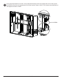
8
Firmly grasp top and bottom of screen. Lift up and push the bottom of the rear supports back until it rests in place
then push the top of the rear supports back until it rests in place. Tighten 1/4-20 x 2.36" screws at top and bottom of
rear supports as shown in detail 7.
1/4-20 SCREWS
DETAIL 7
13 of 18
ISSUED: 07-16-10 SHEET #: 061-9050-4 03-04-11
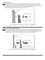
Depth Adjustment
WARNING
• Failure to allow this space for air circulation and to allow heat to dissipate from the screen may effect the visual appearance and/or cause damage to your screen.
8-1 NOTE: The installed display should allow a 1/2" air gap between the front of the screen and the interior surface of
the window. A screen mounted directly against the window will create a dead air space that traps heat which may
affect the funtionality of both the screen and the enclosure mount.
The distance from the rear of the enclosure assembly to the front of the screen should be between 10" - 11".
Support brackets may be moved forward or backward by driving the 1/4-20 x 2.36" screws as shown below.
10" - 11"
(254 mm - 279 mm)
1/4-20 x 2.36" SCREW
FRONT OF
SCREEN
REAR OF
ENCLOSURE
ASSEMBLY
1/4-20 x 2.36" SCREW
14 of 18
ISSUED: 07-16-10 SHEET #: 061-9050-4 03-04-11
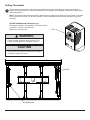
Setting Thermostat
9
Refer to screen manufacturers' requirements for optimal environment temperature. If screen manufacturer's
requirments state that cooler or warmer temperatures are acceptable, use a flatblade screwdriver to adjust dial to
desired temperature.
NOTE: Thermostat inside enclosure assembly will determine at what time the Exhaust Fan will initiate. The Intake
Fan will operate at all times. For all other questions, refer to thermostat instruction sheet included in enclosure
assembly
HEATER INFORMATION (FPE42FH-S only)
Thermostat of heater is not adjustable. The heater will turn
on at 40°±7° and will turn off at 60°±5°.
DIAL
Heater uses a 20 amp fuse.
WARNING
• Frame of heater will be hot when turned on. Turn
heater off allowing frame to cool prior to service.
CAUTION
• Do not postion AV and power cables close to heater
or damge to cables may occur.
HEATER
THERMOSTAT
15 of 18
ISSUED: 07-16-10 SHEET #: 061-9050-4 03-04-11
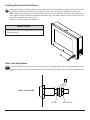
Locking Environmental Enclosure
10
Gently lower bay door. Using key (G) rotate door locks clockwise until key cannot turn. Make sure that the key has
fully rotated to seal enclosure. If key does not fully rotate, door lock may need to be adjusted for a looser seal.
NOTE: Gasket seal of bay door must be compressed to allow for a water tight seal. Test seal of door by inserting a
sheet of paper in between the door seal and the enclsosure seal. If the sheet of paper is easily removed, door lock
may need to be adjusted for a tighter seal.
See step 10-1 below for door lock adjustment.
CAUTION
• Be careful not to pinch your fingers when opening and
closing bay door.
G
Door Lock Adjustment
10-1 To allow for a tighter seal, loosen top nut of door locks 1/4" then tighten bottom nut of door locks against lock tab.
To allow for a more loose seal, loosen bottom nut of door locks 1/4" then tighten top nut of door locks against lock
tab.
FRONT OF BAY DOOR
TOP NUT
16 of 18
BOTTOM NUT
ISSUED: 07-16-10 SHEET #: 061-9050-4 03-04-11
Fan Filter Replacment
11
Filterfan replacement filtermats are sold separately at www.filterfanusa.com, for Filterfan model PF 22000.
Remove cover from Filterfan on side of enclosure assembly (A) as shown in figure 11.1. Remove and replace
filtermat as shown in figure 11.2.
PULL
fig. 11.2
fig. 11.1
17 of 18
ISSUED: 07-16-10 SHEET #: 061-9050-4 03-04-11
© 2010, Peerless Industries, Inc. All rights reserved.
All other brand and product names are trademarks or registered trademarks of their respective owners.
Peerless Industries, Inc.
3215 W. North Ave.
Melrose Park, IL 60160
www.peerlessmounts.com
LIMITED FIVE-YEAR WARRANTY
Peerless Industries, Inc. establishes a warranty period of five years for products manufactured or supplied by Peerless. This period commences from the date of
sale of the product to the original consumer, but will in no case last for more than six years after the date of the product’s manufacture. During the warranty period
such products will be free from defects in material and workmanship, provided they are installed and used in compliance with the instructions established by
Peerless Industries, Inc. Subject to applicable legal requirements, during the warranty period Peerless will repair or replace, or refund the purchase price of, any
such product which fails to conform with this warranty.
Any other warranties prescribed by the law which may apply with respect to such products also are limited in duration to the warranty period specified in this
Limited Five-Year Warranty.
This warranty does not cover damage caused by (a) service or repairs by the customer or a person who is not authorized for such service or repairs by Peerless
Industries, Inc., (b) the failure to utilize proper packing when returning the product, (c) incorrect installation or the failure to follow Peerless’ instructions or warnings
when installing, using or storing the product, or (d) misuse or accident, in transit or otherwise, including in cases of third party actions and force majeure.
In no event shall Peerless be liable for incidental or consequential damages or damages arising from the theft of any product, whether or not secured by a security
device which may be included with the product.
This Limited Five-Year Warranty is in lieu of all other warranties, expressed or implied, and is the sole remedy with respect to product defects. No retailer, dealer,
distributor, installer or other person is authorized to modify or extend this warranty or impose any obligation on Peerless in connection with the sale of any product
manufactured or supplied by Peerless.
This warranty gives specific legal rights, and you may also have other rights provided by the national legislation of the country in which you purchased such
product.
www.peerlessmounts.com
© 2008 Peerless Industries, Inc.
LIMITED ONE-YEAR WARRANTY
Limited one-year warranty on corrosion.
www.peerlessmounts.com
18 of 18
© 2008 Peerless Industries, Inc.
ISSUED: 07-16-10 SHEET #: 061-9050-4 03-04-11