1
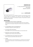
1/3” CCD Color Day/Night
plus Wide Dynamic Range
Outdoor Vandal Dome Camera
Operation Instructions
Model No. ED610
Please read this manual first for correct installation and operation. This manual should be retained for future reference.
The information in this manual was current when published. The manufacturer reserves the right to revise and improve
its products. All specifications are therefore subject to change without notice.
PRECAUTIONS
1. Do not install the camera near electric or magnetic fields.
Install the camera away from TV/radio transmitters, magnets, electric motors, transformers and audio speakers
since the electromagnetic fields generated from these devices may distort the video image.
2.
Never disassemble the camera beyond the recommendations in this manual nor introduce materials
other than those recommended herein.
Improper disassembly or introduction of corrosive materials may result in equipment failure or other damage.
3.
Try and avoid facing the camera toward the sun.
In some circumstances, direct sunlight or may cause permanent damage to the sensor and/or internal circuits.
4.
Keep the power cord away from water and other liquids and never touch the power cord with wet hands.
Touching a wet power cord with hands or touching the power cord with wet hands may result in electric shock.
5.
Never install the camera in areas exposed to oil, gas or solvents.
Oil, gas or solvents may result in equipment failure, electric shock or, in extreme cases, fire.
6.
Cleaning
Do not touch the surface of the sensor directly with the hands. Use a damp soft cloth to remove any dirt from the
camera body. Use lens tissue or a cotton tipped applicator and ethanol to clean the sensor and the camera lens.
Please do not use complex solvents, corrosive or abrasive agents for cleaning.
7.
Do not operate the camera beyond the specified temperature, humidity or power source ratings.
Use the camera at temperatures within -10℃ ~ 50℃ (14℉~122℉) and in an IP66 complaint environment; this
device is not rated as submersible. The input power source is 12VDC/24VAC.
TABLE OF CONTENTS
1. PRODUCT OVERVIEW ............................................................................................................... 3
1.1 Main Features ............................................................................................................................................... 3
1.2 Content List................................................................................................................................................... 3
1.3 Specifications ................................................................................................................................................ 5
1.4 Dimensions............................................................................................................................... 6
1.5 Camera Component Description ................................................................................................. 7
1.6 Front and Back Panel Layout...................................................................................................... 8
1.7 Related Products .................................................................................................................... 9
2. INSTALLATION ................................................................................................................... 10
2.1 Mounting Camera.................................................................................................................... 10
2.1 .1 Drill the Holes .......................................................................................................................................... 10
2.1.2 Mounting ...................................................................................................................................................11
2.2 Adjusting Camera .................................................................................................................... 13
2.2.1 Adjusting Camera Position ......................................................................................................................... 13
2.2.2 Adjusting Zoom and Focus......................................................................................................................... 14
2.2.3 Camera Setting .................................................................................................................... 16
2.2.3.1 OSD User Setup Menu ........................................................................................................................... 16
2.2.4 Close the Camera Cover (after installation is complete) ................................................................................ 16
3. OSD MENU & CONFIGURATION............................................................................................... 18
3.1 Access the user setup menu screen............................................................................................................... 18
3.2 ED610 Menu Tree........................................................................................................................................ 19
3.3 LENS.......................................................................................................................................................... 22
3.4 EXPOSURE ................................................................................................................................................ 22
3.4.1 SHUTTER ................................................................................................................................................ 22
-1-
3.4.2 AGC (Auto Gain Control)............................................................................................................................ 22
3.4.3 SENSE-UP............................................................................................................................................... 22
3.4.4 BLC ......................................................................................................................................................... 23
3.4.5 HSBLC..................................................................................................................................................... 24
3.4.6 D-WDR .................................................................................................................................................... 24
3.4.7 Return...................................................................................................................................................... 24
3.5 WHITE BALANCE CONTROL....................................................................................................................... 25
3.6 DAY NIGHT................................................................................................................................................. 25
3.7 3DNR ......................................................................................................................................................... 26
3.8 SPECIAL .................................................................................................................................................... 26
3.8.1 CAM TITLE............................................................................................................................................... 26
3.8.2 D-EFFECT ............................................................................................................................................... 27
3.8.3 MOTION .................................................................................................................................................. 28
3.8.4 PRIVACY ................................................................................................................................................. 29
3.8.5 SYNC ...................................................................................................................................................... 29
3.8.6 LANGUAGE ............................................................................................................................................. 29
3.8.7 RETURN.................................................................................................................................................. 29
3.9 ADJUST...................................................................................................................................................... 29
3.9.1 SHARPNESS ........................................................................................................................................... 29
3.9.2 BLUE ....................................................................................................................................................... 30
3.9.3 RED......................................................................................................................................................... 30
3.9.4 RETURN.................................................................................................................................................. 30
3.10 RESET...................................................................................................................................................... 30
3.10.1 FACTORY RESET................................................................................................................................... 30
3.10.2 RETURN ................................................................................................................................................ 30
3.11 EXIT ......................................................................................................................................................... 30
-2-
1. PRODUCT OVERVIEW
Amazing color low light sensitivity of .05 lux before the added benefits of digital signal processing
technology, delivered by a 1/3” Sony Super HAD II sensor, is just the beginning with the new EverFocus
ED610. Get color without compromise: 560TVL resolution, your choice of full motion color or true
day/night images in low light without ghosting, plus 120dB Digital Wide Dynamic Range to handle the
most challenging of bright or unbalanced scene lighting conditions. Vandal resistant, IP66, with varifocal
auto iris lens, 3-axis positioning, dual voltage operation and a full suite of OSD Menu and DSP
functions (3D-DNR to save DVR HDD space, privacy masking, 32X digital zoom, mirroring and rotation,
256X sens-up to a max of .0002 lux, and much more) this is the camera you have been waiting for, and
might be the only camera you’ll ever need.
1.1 Main Features
Super HAD II sensor at .05 lux has 5X better native light sensitivity before DSP low light boost
Color without compromise: your choice of full motion color or true day/night images in low light
without ghosting
True Day/Night with ICR module
Starlight super high sensitivity of 0.0002 Lux/F=1.2 is achieved through a sensitivity increase
setting of up to 256x
Digital Wide Dynamic Range expansion to deliver properly exposed images despite bright light
sources, deep shadows and/or unbalanced lighting in the same scene
Provides 3D-Noise Reduction to improve picture clarity while enabling DVRs to improve disk
storage utilization
3 axis positioning for wall or ceiling mounting with flexible angle viewing
Easy to use OSD setup menu
Motion detection for 4 configurable zones
Privacy mask function for 8 configurable zones
Provides digital zoom up to 32x
Dual voltage (12VDC/24VAC) with line lock to AC supply
1.2 Content List
Please be careful when you unpack the box and the electronic devices inside. Check and make
sure that you have all the items listed below inside the original box:
Camera Unit x 1
This Operation Manual x 1
Mounting kit includes:
-Long Screws x 3 (for mounting the base)
-Expanding Anchors x 3
-Washers x 3
Installation Template Sticker x 1
-3-
Video Test Cable x 1
Power Adapter Cable x 1
Desiccant Pack x 1
Focus Aiding Lens Cap (for 9~22mm models only) x 1
Please Note: If an item appears to have been damaged in shipment, replace it properly in its carton
and notify the shipper. If any items are missing, notify your EverFocus Electronics Corp. Sales
Representative or Customer Service. The shipping carton is the safest container in which the unit may
be transported. Save it for possible future use.
-4-
1.3 Specifications
Items
Pickup Device
Video Format
Scanning System
Picture Elements
Horizontal Resolution
Sensitivity
S/N Ratio
Electronic Shutter
Video Outputs
Gamma Correction
Lens Type
Back Light Comp.
Auto Gain Control
White Balance
Sync. Mode
Day & Night
OSD Menu
3DNR
D-WDR
Digital Slow Shutter
Mirror
Digital Zoom
Motion Detection
Privacy Mask
Weatherproof
Vandal Resistant
Power Source
Power Consumption
Operating Temperature
Weatherproof
Dimensions
Weight
Certifications
Parameter
1/3" SONY Super HAD II CCD
NTSC or PAL
NTSC:525 TVL, 60 fields/sec
PAL:625 TVL, 50 fields/sec
768 x 494(NTSC); 752 x 582 (PAL)
560 TVL
0.05Lux/F=1.2(AGC ON); 0.0002Lux/F=1.2(Sens-up 256x)
Over 52dB (AGC off)
1/50 (1/60) ~1/100,000
1. BNC 1.0 Vp-p ,75ohm
2. Additional testing video output 1.0 Vp-p, 75ohm
0.45
Vari-focal lens, Auto Iris, 2.8-10mm (MVB), 9-22mm (MV2)
OFF, BLC, HSBLC Selectable
Off/Low/Middle/High Selectable
ATW/AWB/AWC/Manual/Indoor/Outdoor Selectable
Internal/Line lock external sync.
Yes, (Auto, Color, B/W,EXT)
Yes
Off/On switchable
Outdoor, Indoor
Sens-Up ~ 256x
Off/Mirror/V-Flip/Rotate Selectable
Off/On switchable (up to 32X)
Off/On for 4 Zones
Off/On for 8 Zones
IP66
Yes
12VDC/24VAC
12VDC:3W max.
24VAC:3W max.
-10°C~50°C ; 14°F~122°F
IP66
123mm(O.D.) x 107.8mm (H) ; 4.8” (O.D.) x 4.2” (H)
0.74 kg / 1.6 lbs
CE/FCC
-5-
1.4 Dimensions
123mm x 107.8mm ; 4.8” x 4.2”
Ø 5.143mm//0.2”
Ø 94.7mm/3.78”
-6-
1.5 Camera Component Description
Exterior view
Base
Outer Cover ring
Rotatable cover
Interior view
OSD joystick
Power board
-7-
1.6 Front and Back Panel Layout
Front Panel Layout:
(1)
(2)
(3)
(4)
Back Panel Layout:
(6)
(7)
(5)
-8-
(1) External Light Sensor
External Light sensor is used to detect the lighting level the environment. (The light sensor
is “down” when the internal camera module is properly positioned).
(2) Focus Ring
To set the focus, and loosen the focus ring knob, and turn the ring toward <F> or <N> as
necessary, and re-tighten when the adjustment is complete.
(3) Zoom Ring
To adjust the viewing angle, loosen the zoom ring knob. Turn the ring toward <W> to Zoom
out or <T> to Zoom in as necessary, and re-tighten when the adjustment is complete.
(4) Lens
The included vari-focal, DC iris lens allows manual adjustment of the field of view (zoom & focus).
The choices for focal length range are:
2.8-10mm
9-22mm
(5) Power & Video pigtail cable
Connect power and video to pigtail cable
(6) Test Video Output Connector
When installing the camera, you can use this video connector to connect a portable monitor. This will
allow you to easily adjust camera’s field of view and focus.
(7) OSD Menu joystick: Use the joystick to move the cursor Upwards/Downwards. This is used to
select the item to be set.
Tilt the stick to the right or left. This is used to select or adjust the parameters of the selected item.
Press in on the stick to enter the setup menu. If the item has its own setting menu (sign
), press
the stick again to display the sub- menu.
1.7 Related Products
In addition, you may order the following EverFocus products which are recommended for use with the
camera to achieve the best performance:
L Type Bracket: BA-EDMS
EN220 5.6 inch LCD Test Monitor
-9-
2. INSTALLATION
This chapter will describe, in general terms, how to install the ED610 camera.
STEPS:
2.1. Mounting Camera:
1. Drill the Holes. See 2.1.1
2. Mounting: See 2.1.2
2.2. Adjusting Camera:
1. Adjust the camera position. See 2.2.1
2. Adjusting Zoom and Focus See 2.2.2
3. Camera Setting. See 2.2.3
4. How to close camera cover after installation. See 2.2.4
Warning
•
•
To prevent electrical shock, turn off the electrical power before making electrical connections.
Do not expose the camera to water or moisture while open during installation, nor try to operate
it while open in wet areas. Once properly installed and sealed, the dome is IP66 rated against
water infiltration.
2.1 Mounting Camera
2.1 .1 Drill the Holes
1. Paste the drilling template on the ceiling or wall
2. Drill 4 holes, 1 for the power/video cable, 3 for screws A, B and C.
Screw hole A
Screw hole C
Installation sticker
Screw hole B
- 10 -
Wire outlet hole for
Surface mounting
Power/Video Cable
Screw A,B,C
Camera base
2.1.2 Mounting
1. Take off camera’s cover by rotating the cover counter clockwise.
Loose outer cover ring first
Take off camera’s cover
- 11 -
2. Pull the cables to be connected to the power and video cables from the ceiling or wall.
Video output
Power input
3. Fix the camera base to ceiling or wall by using 3 screws and washers. The washers are used to
create the IP66 seal and must be used.
Ceiling Mount:
- 12 -
Wall Mount:
2.2 Adjusting Camera
2.2.1 Adjusting Camera Position
Adjust the camera to best angle for viewing.
When you install on the ceiling, change angle of view by turning these joints.
Module can be adjusted up and down
- 13 -
2.2.2 Adjusting Zoom and Focus
It is highly recommended to use an EverFocus Test Monitor to set up the camera. Find the Video test
connection on the back of the camera module. Connect using the video cable included in the package.
Video out
Connect with Test Monitor
1. Loosen the zoom ring knob, and then turn the ring towards <W> or <T> as necessary to obtain the
desired view angle.
W side (Zoom out)
The viewing range will be wider and the subject is smaller.
T side (Zoom in)
The viewing range will be smaller and the subject is larger.
2. Loosen the focus ring knob, then turn the ring towards <∞> or <N> as necessary to obtain a clear
video image.
3. Repeat steps 1 and 2 until the best image is obtained. Once the lens setting is complete, tighten
the zoom and focus ring knobs.
Important Note when focusing a 9-22mm Lens
To adjust lens zoom and focus, if using the 9~22mm lens model ED610 camera, the focus aiding lens
cap must be used to simulate the dome being closed. Follow the steps below to ensure that camera
will stay in focus when the dome is installed.
Step 1
Take the included focus aiding lens cap (shown below) from its small plastic bag.
- 14 -
Step 2 Open the dome cover and place the Focus aiding lens cap on the lens, making sure that the
cap’s notch is resting on the zoom knob.
Step 3 With cap on, adjust the focus and zoom rings by loosening the knobs and turning the rings
until subject is in focus. Retighten the knobs when done.
Step 4 When finished adjusting focus and zoom, remove the focus aiding cap from the camera lens,
replace the dome cover and secure the cover by turning it clockwise. See Section 2.2.4 below for
additional information.
NOTE: It is recommended to put the desiccant pack under the bracket. Or, use a cable tie to secure it
before placing the cover back on the camera.
- 15 -
2.2.3 Camera Setting
2.2.3.1 OSD User Setup Menu
This camera utilizes an On Screen Display (OSD) user setup menu.
Please refer to Chapter 3 OSD Menu & Configuration, to get more details about OSD menu usage.
2.2.4 Close the Camera Cover (after installation is complete)
The ED610 is specially designed with one inner cover and one outer cover ring for water-proofing and
ease of installation. Please follow these instructions for closing the camera cover.
1. Align the window in the cover with the lens
2. Push the interior cover toward the base, until it completely covers the whole red gasket and is lined
up parallel with camera base. (The cover must be aligned with the camera base or it cannot be
closed. Then turn the outer cover ring clockwise to secure it tightly to the camera base.
Push the inner cover and
cover the whole red gasket
Outer cover ring
- 16 -
Correct
Wrong (not aligned)
3. If the lens is not aligned with the window, loosen the outer cover, adjust the inner cover so that the
lens aimed exactly at the window.
Slightly adjust the cover
4. Tighten the outer cover ring until it is firmly secured.
Turn the external ring
- 17 -
3. OSD MENU & CONFIGURATION
This chapter introduces how to configure the camera OSD menu.
Joystick
3.1 Access the user setup menu screen
I.
Press inward on the end of the joystick
The menu screen will appear on the monitor.
II.
Navigating with the joystick
Angle the joystick or to move the cursor up or down. Angle the joystick or to
adjust the mode or value of a setting.
III.
Switching to sub-menu screens
When an item with sub-menu is selected, press inward on the end of the joystick to
switch to the sub-menu for further settings.
NOTE:
For those selected items with “
” sign at the end, there is a sub-menu for further settings.
IV.
Return to previous page
Press the SET button to return to previous page if the choice displayed is RETURN.
V.
Close the menu screen
Press the SET button to exit the menu system if the choice displayed is END (sub-menu)
or EXIT (main menu only).
- 18 -
3.2 ED610 Menu Tree
- 19 -
- 20 -
- 21 -
3.3 LENS
1. When the SETUP menu is displayed on the screen, please direct the arrow to point to “LENS” by
moving the joystick UP and DOWN.
NOTE:
The brightness of the screen can be adjusted in the BRIGHTNESS sub menu. The level can be
adjusted from 0 to 100.
2.
Select “RET” to save all settings in the LENS menu and returns to the previous menu.
Select “END” to save all the menu settings and exit from the OSD menu.
3.4 EXPOSURE
When the SETUP menu is displayed, direct the arrow to EXPOSURE and press in on the joystick.
3.4.1 SHUTTER
1.
When the EXPOSURE menu is displayed on the screen, please direct the arrow to point
“SHUTTER” by moving the joystick UP or DOWN.
2.
Select the shutter mode by moving the joystick LEFT or RIGHT.
Select from x256, x128, x64, x32, x16, x8, x4, x2, 1/60, FLK, 1/125, 1/500, 1/2000, 1/5000,
1/10000, 1/00000.
FLK:
Please select “FLK” mode if flickering occurs on the screen, because of an irregular balance
between illumination and scan frequency. NTSC model: 1/100, PAL model: 1/120.
3.4.2 AGC (Auto Gain Control)
1. Please direct the arrow to point to “AGC” by moving the joystick UP and DOWN.
2. Select the mode you would like to operate by moving the joystick LEFT or RIGHT. The more the
level of gain increases, the brighter the screen; however, the level of noise increases as well.
Please select from HIGH, MIDDLE, LOW and OFF.
3.4.3 SENSE-UP
SENSE-UP is used to keep a brilliant, vivid screen image by automatically detecting changes in the
level of light under low light level conditions.
1.
Please direct the arrow to point to “SENSE-UP” by moving the joystick UP and DOWN.
2.
Select the mode you would like to operate by moving the joystick LEFT or RIGHT.
AUTO:
Low light level auto mode.
OFF:
The function is disabled.
- 22 -
NOTES:
1 The maximum amplification in low light level situations can be adjusted by pressing the
○
SETUP button in “AUTO” mode. This sets an upper limit on the ‘boost’.
2 The image becomes brighter when the setting increases; however, the after image increases
○
as well. Due to the increased light sensitivity of the Super Had II chip, far less DSP ‘boost’ is
needed, resulting in color or B/W images in low light with minimal ghosting.
3 Please note that spots and noise may appear if light amplification increases when SENSE-UP
○
is operating. This is a normal phenomenon, controllable with DNR.
3.4.4 BLC
Video gain can be adjusted automatically to correct the exposure of subjects that are in front of a
bright light source.
1.
Please direct the arrow to point to “BLC” by moving the joystick UP and DOWN.
Select the BLC mode by pressing the LEFT or RIGHT button. Then make adjustments as
2.
below:
GAIN:
Select from High, Middle and Low.
DEFAULT:
Set the factory default values for BLC.
LEFT/RIGHT:
Set the Left/Right side of an area for the BLC to be adjusted. The value adjustable is 0~6.
WIDTH:
Set the width of an area for the BLC to be adjusted. The value adjustable is 0~6.
TOP/BOTTOM:
Set the Top/Bottom side of an area for the BLC to be adjusted. The value adjustable is 0~6.
HEIGHT:
Set the height of an area for the BLC to be adjusted. The value adjustable is 0~6.
Select “RET” to save all settings in this menu and returns to the previous menu.
Select “END” to save all the menu settings and exit.
- 23 -
3.4.5 HSBLC
HSBLC (Highlight Suppression BLC) is used to reduce the brightness of light sources in a specific
area. It is activated only in a low illumination environment to minimize the effects of glare from bright
lights such as spotlights, street lights or headlights in the field of view. Where ‘traditional’ BLC can
increase the exposure of a dark area surrounded by a brighter area, HSBLC can decrease the
exposure of bright areas surrounded by darker areas.
1. Please direct the arrow to point to “BLC” by using the UP and DOWN buttons.
2. Select the HSBLC mode by pressing the LEFT or RIGHT button. Then make adjustments as
below:
LEVEL: Adjust the sensitivity level for HSBLC from 0 to 8.
DEFAULT: Set the factory default values for HSBLC.
LEFT/RIGHT: Set the Left/Right side of an area for the HSBLC to be adjusted. The value
adjustable is 0~6.
WIDTH: Set the width of an area for the HSBLC to be adjusted. The value adjustable is 0~6.
TOP/BOTTOM: Set the Top/Bottom side of an area for the HSBLC to be adjusted. The value
adjustable is 0~6.
HEIGHT: Set the height of an area for the HSBLC to be adjusted. The value adjustable is 0~6.
Select “RET” to save all settings in HSBLC menu and returns to the previous menu.
Select “END” to save all the menu settings and exit from the OSD menu.
3.4.6 D-WDR
When there are both bright and dark areas at same time, this function can make both areas
properly exposed.
1. Please direct the arrow to point to “D-WDR” by using the UP and DOWN buttons.
2. Select the mode you would like to operate by moving the joystick LEFT or RIGHT.
OFF: Disables D-WDR function
INDOOR: Select this option if you are in an indoor environment.
OUTDOOR: Select this option if you are in an outdoor environment.
3.4.7 Return
Select “RET” to save all settings in the EXPOSURE menu and returns to the previous menu.
Select “END” to save all the menu settings and exit from the OSD menu.
- 24 -
3.5 WHITE BALANCE CONTROL
The screen color can be adjusted by using the WHITE BALANCE function.
1. Please direct the arrow to point to “WHITE BAL” by moving the joystick UP and DOWN.
2. Please select the mode you would like to operate by moving the joystick LEFT or RIGHT.
Please select one of the 6 modes below:
ATW (Auto Tracking White Balance):
This mode can be used within the color temperature range from 5,500°K to 6,000°K (eg,
fluorescent light, outdoor, sodium vapor lamp or inside tunnels).
AWB:
This mode can be used within the color temperature range from 2,500°K to 10,000°K.
AWC->SET: To find the optimal setting for the current luminance environment in this mode, point
the camera toward a sheet of white paper, and press middle of joystick. If the environment
changes, you have to readjust it.
MANUAL: The manual adjustment mode enables a more precise adjustment. Please select ATW
or AWC first. Then change to manual adjustment mode and press middle of joystick. Set the
suitable color temperature, and increase or decrease the red and blue color values at the same
time while checking the color changes of the objects in view.
Select “RET” to save all settings in this menu and returns to the previous menu.
Select “END” to save all the menu settings and exit.
INDOOR:
Select this option when the color temperature is 5,600°K.
OUTDOOR:
Select this option when the color temperature is 3,300°K.
Press “RET” to save all settings in this menu and returns to the previous menu.
Press “END” to save all the menu settings and exit
3.6 DAY NIGHT
These settings control the operation of the camera when the illumination level changes. Choices are
Color at all times; B/W at all times; or color when illumination is bright, switching to B/W in low light.
B/W: The picture is always displayed in B/W.
BURST: OFF/ON.
ON: Retains the color burst information; minor color noises may appear when ambient
illumination is low.
OFF: With color burst signal off, picture will be pure B/W.
Return: Press “RET” to save all settings in the DAY/NIGHT menu and returns to the previous
menu.
Press “END” to save all the menu settings and exit.
- 25 -
COLOR: The picture is always displayed in color, even at low light levels.
AUTO: The picture switches to color in a normal (bright) environment and switches to B/W
when the ambient illumination is low. The switching point is determined by the AGC level.
Note: AGC selection must be set as middle or high in order to employ the auto
switching function.
Delay: Set the switchover delay time from 0~63 seconds.
S-Level: Set the start level from 0~100.
E-Level: Set the end level from 0~100.
EXT:
The picture switches to color in a normal environment and switches to B/W when the ambient
illumination is low. The switching condition is determined by the light sensor alongside the lens.
3.7 3DNR
3DNR reduces the background noise in a low luminance environment.
OFF:
Disables 3DNR to keep the same amount of noise.
ON:
Enables 3DNR to reduce the noise.
Level: adjust noise reduction level from 0~100.
Return: Select “RET” to save all settings in 3DNR menu and returns to the previous
menu.
Select “END” to save all the menu settings and exit from the OSD menu.
3.8 SPECIAL
In this section, user can control special settings including Cam Title, D-Effect, Motion, Privacy, Sync,
Language and Return.
1. Please direct the arrow to point to “SPECIAL” on the SETUP menu by moving the joystick UP and
DOWN.
2. Select the mode you would like to operate by moving the joystick LEFT or RIGHT.
3.8.1 CAM TITLE
Input a camera title and it will be displayed on the monitor.
1) Please direct the arrow to point to “CAMERA” by moving the joystick UP or DOWN.
2) Select “ON” by moving the joystick LEFT or RIGHT.
3) Press in on the joystick.
4) Maximum 15 letters can be used for the ID.
Moving the joystick UP and DOWN position the cursor on the letter to be chosen.
Press in on the joystick to lock in the letters. Repeat as necessary.
5) Once a name has been selected, please choose a position where you would like to
display the name.
Move the cursor onto “POS” and press in on the joystick.
The name will appear at the top left hand corner.
Angle the joystick in any direction to select the desired position to display the
name. Press in on the joystick to lock in the position.
- 26 -
6) If you would like to cancel the ID entered, please move the cursor to “CLR”, press in on
the joystick, and all the letters entered will be deleted.
7) Select “END” and press in on the joystick to complete the ID input.
3.8.2 D-EFFECT
3.8.2.1 FREEZE
(Note that practical application of this feature requires direct access to the camera menu in real
time).
OFF:
Select “OFF” to view moving pictures.
ON:
Select “ON” to view still pictures.
3.8.2.2 MIRROR
OFF:
Disable the effects.
MIRROR:
Sets a horizontal image inversion.
V-FLIP:
Set a vertical image inversion.
ROTATE:
Rotate the image 180˚.
3.8.2.3 D-ZOOM
Set the digital zoom.
OFF:
Disable the D-ZOOM function.
- 27 -
ON:
D-Zoom: Select digital zoom from X1.0 up to X32.
To control the portion of the magnified image in view (0 is the center of the image):
Pan: Select pan digital zoom from -100 to 100.
Tilt: Select tilt digital zoom from -100 to 100.
Return: Select “RET” to save all settings in D-ZOOM menu and returns to the previous
menu.
Select “END” to save all the menu settings and exit from the OSD menu.
3.8.2.4 GAMMA
To adjust displayed brightness from 0.05 up to 1.0.
3.8.2.5 NEG. IMAGE
Allows user to create a negative of the original image. A negative image is a tonal inversion of a
positive image, in which light areas appear dark and vice versa. A negative color image is
additionally color reversed, with red areas appearing cyan, greens appearing magenta and blues
appearing yellow.
3.8.2.6 RETURN
Select “RET” to save all settings in D-EFFECT menu and returns to the previous menu.
Select “END” to save all the menu settings and exit from OSD menu.
3.8.3 MOTION
This camera enables you to observe movements of objects in 4 different areas on the screen,
and the message “MOTION DETECTED” appears on the screen when movement is detected;
this may help to improve operational efficiency. The camera detects an object’s movement by
sensing changes in the pixels displayed.
-OFF: Disables the MOTION function.
-ON:
AREA SELECT: Please select the area you would like to detect from the 4 areas in
AREA SELECT mode
AREA DISPLAY: Select “ON” to use the motion area selected in sensitivity. Select “OFF”
to disable this function.
LEFT/RIGHT: Set the coordinate of the horizontal axis 5~66.
WIDTH: Set the size of horizontal area 0~93.
TOP/BOTTOM: Set the coordinate of the vertical axis 1~60.
HEIGHT: Set the size of vertical area 0~60.
SENSITIVITY: Set the sensitivity level for the motion trigger by selecting from 0~40.
When the sensitivity value is high, motion detection sensitivity increases to sense very
small movements and vice versa.
MOTION VIEW: Select “ON” to display motion detection pixels in the live view.
Select “RET” to save all settings in MOTION menu and returns to the previous menu.
Select “END” to save all the menu settings and exit from OSD menu.
- 28 -
3.8.4 PRIVACY
This mode covers the areas you do not want to see on the screen.
OFF:
Disable the PRIVACY function.
ON:
AREA SELECT: Please select the area you would like to hide from the 8 areas in AREA
SELECT mode
AREA DISPLAY: Select “ON” to use the area selected in the AREA SELECT. Select
“OFF” to disable this function.
LEFT/RIGHT: Set the coordinate of the horizontal axis 6~98.
WIDTH: Set the size of horizontal area 0~93.
TOP/BOTTOM: Set the coordinate of the vertical axis 0~60.
HEIGHT: Set the size of vertical area 0~61.
COLOR: Set area color. It is selectable from 0 to 15.
Select “RET” to save all settings in PRIVACY menu and returns to the previous menu.
Select “END” to save all the menu settings and exit from OSD menu.
3.8.5 SYNC
There are two SYNCHRONIZATION modes: INTERNAL and EXTERNAL LINE-LOCK. In
LINE-LOCK mode, the video signal is synchronized to the frequency of the incoming AC power.
The Line-Lock synchronization can only be used when the supply power is 24VAC/60Hz (NTSC
models) or 50Hz (PAL models).
INT:
Internal synchronization
L/L:
External line-lock synchronization
3.8.6 LANGUAGE
Select OSD language. ED610 camera supports multiple languages.
3.8.7 RETURN
Select “RET” to save all settings in SPECIAL menu and returns to the previous menu.
Select “END” to save all the menu settings and exit from OSD menu.
3.9 ADJUST
Adjust sharpness, Blue and Red level in this section.
3.9.1 SHARPNESS
The contour of the video image becomes cleaner and more easily distinguished as the level of
SHARPNESS increases. If the level is set too high it may affect the video image and cause noise.
The available range of level is 0~31.
- 29 -
3.9.2 BLUE
Adjust image’s blue level. The available range of level is 0~100.
3.9.3 RED
Adjust image’s red level. The available range of level is 0~100.
3.9.4 RETURN
Select “RET” to save all settings in ADJUST menu and returns to the previous menu.
Select “END” to save all the menu settings and exit from OSD menu.
3.10 RESET
3.10.1 FACTORY RESET
Reset to the default settings.
3.10.2 RETURN
Select “RET” to save all settings in RESET menu and returns to the previous menu.
Select “END” to exit from OSD menu.
3.11 EXIT
Save all the menu settings and exit.
NOTE:
If you quit the Menu without pressing EXIT, all the settings you previously modified will NOT
be saved.
- 30 -
EverFocus Electronics Corp.
Headquarter Office
12F, No.79 Sec.1 Shin-Tai Wu Road,
Hsi-Chi, Taipei, Taiwan
Tel: +886-2-26982334
Fax: +886-2-26982380
Beijing office
Room 609,Technology Trade Building.
Shangdi Information Industry Base,
Haidian District,Beijing China
Tel: +86-10-62971096
Fax: +86-10-62971423
European Office
Albert-Einstein-Strasse 1,
D-46446 Emmerich, Germany
Tel: +49-2822-9394-0
Fax: +49-2822-939495
Japan Office
1809 WBG Marive East 18F,
2-6 Nakase, Mihama-ku,
Chiba city 261-7118, Japan
Tel: +81-43-212-8188
Fax: +81-43-297-0081
USA California Office
1801 Highland Ave. Unit A
Duarte, CA 91010 ,U.S.A
Tel: +1-626-844-8888
Fax: +1-626-844-8838
USA New York Office
415 Oser Ave Unit S
Hauppauge, NY 11788
Sales: +1-631-436-5070
Fax: +1-631-436-5027
Your EverFocus product is designed and
manufactured with high quality materials and
components which can be recycled and reused.
This symbol means that electrical and electronic
equipment, at their end-of-life, should be
disposed of separately from your household
waste.
Please, dispose of this equipment at your local
community waste collection/recycling centre.
In the European Union there are separate
collection systems for used electrical and
electronic product.
Please, help us to conserve the environment we
live in!
Ihr EverFocus Produkt wurde entwickelt und
hergestellt
mit
qualitativ
hochwertigen
Materialien und Komponenten, die recycelt und
wieder verwendet werden können.
Dieses Symbol bedeutet, dass elektrische und
elektronische
Geräte
am
Ende
ihrer
Nutzungsdauer vom Hausmüll getrennt
entsorgt werden sollen.
Bitte entsorgen Sie dieses Gerät bei Ihrer
örtlichen kommunalen Sammelstelle oder im
Recycling Centre.
Helfen Sie uns bitte, die Umwelt zu erhalten, in
der wir leben!
P/N: MED6G00100
- 31 -