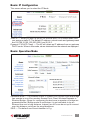
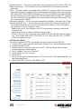
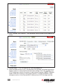
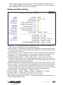
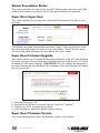
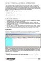
1
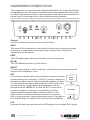
Wireless
Super G
Outdoor
PoE Access
Point and
Bridge
user
manual
Model 503679
INT-503679-UM-0808-02
introduction
Thank you for purchasing the INTELLINET NETWORK SOLUTIONS™ Wireless
Super G Outdoor PoE Access Point and Bridge, Model 503679.
This professional Wireless G access point and bridge delivers a wide assortment
of features that appeal to wireless users requiring a durable, flexible and powerful
solution. The housing is made of rugged aluminum, providing superior protection
that includes a water-resistance rating of IP66 and the ability to withstand wind
speeds up to 120 km/h (75 mph). And with PoE (Power over Ethernet) — the
latest in Ethernet technology — you can place equipment in locations where
there are no AC power connections. With power being transferred through the
Ethernet cable, the unit can be installed wherever the RJ45 cable can be run!
The instructions in this user manual help make setup and operation quick and
simple, so you’ll also soon be enjoying the benefits of these additional features:
• Fully compatible with IEEE 802.11b/g WLAN standard
• Up to 108 Mbps network data transfer rate
• Up to 5 km (3 mi.) wireless distance in PtP bridging mode
• Integrated 9 dBi panel antenna
• N-type connector for connection of an external high-gain antenna
• Supports Wireless Access Point, Repeater, Bridging and AP Client modes
• Supports WEP and WPA (TKIP and AES) data encryption
• Supports MAC filtering for wireless clients
• VPN pass-through for IPSec, PPTP and L2TP
• Web, Telnet and SNMP management
• Configuration backup and restore via Web interface
• Includes Microsoft Windows-based configuration and management utility
• Includes PoE injector (non-IEEE802.3af compliant)
• Lifetime Warranty
Package Contents
• Outdoor AP
• 48 V DC power adapter (PoE injector)
• Power cord
• Screws, washers and U-bolts
• Mounting brackets (for walls or pole mount)
• Grounding wire
• RJ45 waterproof plastic plug (IP67)
• CD-ROM (utility)
• User manual
3
table of contents
section page
HARDWARE/CONNECTIONS.........................................................................6
BASIC IP NETWORKING.................................................................................7
CONFIGURATION............................................................................................8
Basic: Site Survey......................................................................................8
Basic: Administration.................................................................................8
Basic: IP Configuration..............................................................................9
Basic: Operation Mode..............................................................................9
AP Repeater Mode..............................................................................10
Wireless Bridge Mode..........................................................................12
Advanced: Radio Setting.........................................................................13
Advanced: Security Setting.....................................................................14
WEP Security.......................................................................................14
WPA-PSK Security..............................................................................14
WPA Security.......................................................................................15
Advanced: MAC Access Control..............................................................15
Advanced: Protocol Filter.........................................................................15
Advanced: SNMP Configuration..............................................................16
Advanced: Miscellaneous........................................................................16
Status: System Status..............................................................................17
Status: Association Status.......................................................................17
Super User: Super User...........................................................................18
Super User: Firmware Updgrade.............................................................18
Super User: Firmware Version................................................................18
UTILITY INSTALLATION & OPERATION.......................................................19
Software Installation................................................................................19
Operation.................................................................................................19
SPECIFICATIONS..........................................................................................21
NOTE: Some screen images have been modified to fit the format of this manual.
4
CONTENTS
Regulatory Statements
This equipment has been tested and found to comply with the limits for a Class B
digital device, pursuant to Part 15 of the Federal Communications Commission
(FCC) Rules. These limits are designed to provide reasonable protection against
harmful interference in a residential installation. This equipment generates, uses
and can radiate radio frequency energy and, if not installed and used in accordance
with the instructions, may cause harmful interference to radio communications.
However, there is no guarantee that interference will not occur in a particular
installation. If this equipment does cause harmful interference to radio or television
reception, which can be determined by turning the equipment off and on, the user
is encouraged to try to correct the interference by one of the following measures:
• Reorient or relocate the receiving antenna.
• Increase the separation between the equipment and receiver.
• Connect the equipment into an outlet on a circuit different from that to which the
receiver is connected.
• Consult the dealer or an experienced radio/TV technician for help.
FCC Caution
Any changes or modifications not expressly approved by the party responsible
for compliance could void the user’s authority to operate this equipment. This
device complies with Part 15 of the FCC Rules. Operation is subject to the
following two conditions: 1) This device may not cause harmful interference, and
2) This device must accept any interference received, including interference
that may cause undesired operation.
FCC Radiation Exposure Statement
This equipment complies with FCC radiation exposure limits set forth for an
uncontrolled environment. This equipment should be installed and operated with
a minimum distance of 20 cm (approximately 8 inches) between the radiator and
your body. This transmitter must not be co-located or operated in conjunction with
any other antenna or transmitter.
The availability of some specific channels and/or operational frequency bands
is country-dependent: Channels are firmware-programmed at the factory to match
the intended destination. The firmware setting is not accessible by the end user.
European Union Notice
This product complies with R&TTE Directive (1999/5/EC) and the following:
• EN 60950-1:2001+A11:2004 Product Safety
• EN 300 328 Technical requirement for radio equipment
• EN 301 489-1/-17 General EMC requirements for radio equipment
• EN 50385
REGULATORY STATEMENTS
5
HARDWARE/CONNECTIONS
The components, connections and indicators depicted in the image (and directly
corresponding to the unit itself) are detailed below as they appear from left to right.
In addition, there are four holes on the rear panel of the device (the underside, as
shown here) for attaching either of the included mounting brackets.
Ground
Use the included ground wire to ground the device.
Vent
This special Gore membrane vent protects the device by allowing any water
moisture to escape while preventing excess moisture from entering. No
adjustments are necessary.
PWR
This LED lights green whenever the device is receiving power.
WLAN
This LED flashes blue during LAN activity.
RESET
To return any settings to factory defaults, unscrew the dust cap and press the
button for five seconds or more.
EXT
If you require a higher-gain external antenna, unscrew the dust
cap and make your connection. The EXT connector features a
mechanical switch function that automatically disables the builtin 9-dBi directional antenna and redirects the RF signal to the
external antenna. Conduct any signal alignment from the
external antenna. NOTE: Do not use the EXT connector for
any other purpose, as doing so could interfere with the
sophisticated mechanical switch inside the device. If the
cable used for an external antenna connection includes a
built-in surge protector, connect the shorter side of the cable to
the Wireless Super G Outdoor PoE Access Point and Bridge.
External
Antenna
Model 503679
Surge
Protector
PoE
Unscrew the dust cap and connect the AP/bridge to the included PoE injector.
6
HARDWARE/CONNECTIONS
basic ip networking
IP (Internet Protocol)
IP stands for Internet protocol. In an IP network, every device has a unique IP
address (e.g., 192.168.10.35) to identify itself. There are two ways of assigning
an IP address to a PC or router: static and automatic (DHCP). Static IP addresses
are keyed in manually, while dynamic IPs are distributed by a DHCP server.
Ports
Every packet of traffic is identified by its source and destination addresses, which
ensures that the packet arrives at the correct destination. A port number is also
embedded in each packet to identify which software application generated and
uses that packet. If it blocks a certain port number, it prevents that particular
software from using the connection.
Static IP Address
Static IP addressing ensures that the device will always have the same IP address.
Static addressing is commonly used for your servers.
Dynamic IP Address
A dynamic IP address is one that is automatically assigned to a PC. These IP
addresses are “dynamic” because they are only temporarily leased to the PC
when it connects to the network. This is the most convenient and common way
of managing IP addresses in a network. The server that manages this pool of IP
addresses is called the DHCP server. This product has a DHCP server built in to
simplify the network management.
DHCP (Dynamic Host Configuration Protocol)
The PC obtaining an IP address from the server is called the DHCP client. If there
is already a DHCP server running on your network, you must disable one of the
two DHCP servers, as running more than one will cause network problems.
Wireless LAN
A wireless LAN (WLAN) is a computer network that transmits and receives data
using radio signals instead of cables. WLAN has become common in homes,
offices, airports and public hotspots, and can support the same applications and
software that run on a wired network (LAN). It’s also more convenient, since it
eliminates the need to lay Ethernet cables in a home or office. WLAN networking
involves a few additional parameters that need to be configured:
SSID — The service set identifier is the “network name” for the WLAN network,
and can be any set of characters or numbers. The DHCP client “sniffs” the
radio frequencies for an AP with the same SSID, then locks onto the AP (thus,
they’re “associated”). To enable Plug and Play convenience, most client cards can sniff frequencies to extract available SSIDs for user selection.
Encryption — WLAN traffic can be captured by anybody to be read! The solution
is to use encryption to make the traffic appear as random characters to an
eavesdropper. Both the AP and client must use the same encryption standard
and key to enable them to decode the “rubbish.” If the encryption settings are
mismatched, the client and AP cannot associate. WEP (Wired Equivalent
Privacy) is the most common WLAN encryption standard.
Frequency — This device operates in the 2.4 GHz band. Depending on local
regulation, not all the frequencies may be available in every country. Frequency is
configured on the AP only: The client searches for the AP and locks onto that
AP’s channel.
BASIC IP NETWORKING
7
Signal Strength — Radio signals drop in power over distance, and even if all the
settings are correct, low signal strength makes association impossible. The
usable distance between the AP and client can range from a few meters
indoors to a few kilometers. When setting up the client, make sure that:
• The WLAN signals do not have to pass through too many concrete walls and
metal structures to reach the client.
•There is a line of sight between the AP and client device.
Interference — Interference happens when two clients with the same channels
are placed near one another. The speed of the network drops and the signal
strength fluctuates.
Roaming — Association happens when the SSID, Encryption and MAC Address
Control settings are correct between the AP and client. If two APs with these
same settings are located in the same area, the client would choose to
associate to the one that gives it a better signal strength. The client would
“roam” over to the second AP when he moves nearer to it, switching AP and
frequency as he does so.
CONfiguraTION
Before configuring the Wireless Super G Outdoor PoE Access Point and Bridge,
check that the hardware connections have been properly made. If your PC is
wireless, check its card utility to make sure that the signal strength is good and
that the LEDs light up on the device.
Open a Web browser and enter the
device’s LAN IP address in the
browser’s address field. The default
address is 192.168.10.100.
The Configuration Menu’s left-hand-side navigation panel presents four main
sections — Basic, Advanced, Status and Super User — which are detailed
below along with each of their subsections.
Basic: Site Survey
This screen presents some of the current basic settings.
Basic: Administration
This screen allows you to change the username and password for admin user
and end user. Both defaults are “admin,” reverted to after every resetting to the
factory defaults. NOTE: Both the username and the password are case sensitive.
After making any changes, reboot the device for these changes to take effect.
8
CONFIGURATION
Basic: IP Configuration
This screen allows you to select the IP Mode.
Static IP — When you boot up the AP for the first time, it is in Static mode, and you assign a static IP. The default IP address, subnet mask and gateway mask
are 192.168.10.100, 255.255.255.0 and 0.0.0.0.
Dynamic IP (DHCP Client) — The AP will obtain an IP address from an upstream
DHCP server. When in this mode, values obtained from the network are displayed.
Basic: Operation Mode
Operation Mode — The Wireless Super G Outdoor PoE Access Point and Bridge
can operate in one of four modes: Access Point, Client, Wireless Repeater or Ethernet Bridge. (Steps for configuring the device as a repeater or bridge are
presented below.) Bridge mode is used when it is not advisable to lay an
Ethernet line over a long distance. Instead, two APs can be set up to connect
over this distance, acting as the wired backbone.
SSID — The default service set identifier is 11g.
CONFIGURATION
9
Wireless Mode — The device operates in the frequency of 2.4 GHz for 802.11g.
Radio Frequency — Set manually or use SmartSelect for automatic channel
selection.
WDS — Enable, disable or disable with multiple PC support. When the wireless
distribution system is enabled, all PCs connected to a bridge/AP can communicate
with each other. When WDS is disabled, only PCs connected to the same bridge/
AP can communicate with each other. When disabled with multiple PC support,
all PCs connected to a bridge/AP can communicate with each other, even if the
AP cannot support WDS.
Advanced Settings — This is to set the distance for bridging. The default is 4-6 km.
Remote AP MAC List — As a bridge, the device will only associate with an AP
whose MAC address is in the list. Enter the MAC address of the AP without
any spacing in front or behind it. Also:
•Make sure you’re connecting to the AP only through a directly connected
Ethernet link.
•Adjust the device to obtain sufficient signal quality.
•When in Client mode, generate some traffic between the AP and the bridge:
e.g., for a bridge with an IP of 192.168.1.33, run “ping 192.168.1.33-t-l 10000”
at the command prompt.
AP Repeater Mode
This device, Model 503679, will repeat only with another Model 503679.
1. Connect AP1 to your network and choose “Access Point” as the Operation Mode.
2. Assign an SSID to AP1.
3. Select a Radio Frequency channel for AP1. The Operation Mode screen
should appear as shown above.
4. Click “Update,” then click “Reboot.”
5. Connect AP2 to your network.
6. Select AP2.
7. Go to the Operation Mode screen on AP2 and select “Wireless Repeater” as
the Operation Mode.
8. Match the SSID on AP2 to the SSID of AP1.
10
CONFIGURATION
9.
From the Basic: Site Survey screen, copy the MAC address (BSSID) of AP1
and add it to the Remote AP MAC Address list on the Operation Mode screen.
Click “Update” and “Reboot.” The Operation Mode screen should now
appear as below.
10.From the Status menu, go to the Association Status screen. Once you see the
association of AP1 with AP2 and AP2 with AP1, you may unplug AP2 from
the network and move it to the permanent location.
Note: In Repeater mode, both APs must have the same SSID and be on the
same channel. AP2 (Wireless Repeater) must have the MAC address of AP1
(Access Point mode) in the Remote MAC Address list in order to associate with
AP1. Note: Also, the default gateways of AP1 and AP2 should be the IP address
of the router on your network.
Wireless Bridge Mode
1. Connect AP1 to your network.
2. Go to the Basic: Operation Mode screen and select “Wireless Bridge” as the operation mode.
3. From the Basic: Site Survey screen, copy the MAC address (BSSID) of the AP
you’re bridging with and add it to the Remote AP MAC Address list on the
Operation Mode screen.
CONFIGURATION
11
4. Click “Update” and “Reboot.” The Operation Mode screen should appear as
below.
5.
6.
Repeat Steps 1–4 for the second AP you are bridging to.
From the Status menu on AP1 (bridge) and AP2 (bridge), go to the Association Status screen to verify that the two are associating. If so, AP1 (bridge) and
AP2 (bridge) are ready to be placed in permanent locations. Note: In Bridge
mode, both APs must be on the same channel. The MAC address of AP1
(bridge) must be in the Remote MAC Address list of AP2 (bridge) and the
12
CONFIGURATION
MAC address of AP2 (bridge) must be in the Remote MAC Address list of
AP1 (bridge). Note: Also, the default gateways of AP1 and AP2 should be
the IP address of the router on your network.
Advanced: Radio Setting
Data Rate — You can enter different values, such as 11 Mbps or 24 Mbps; but
“Best” lets the AP determine the optimal data rate.
Transmit Power — Sometimes it’s useful to decrease the coverage range of each
AP so that more APs can be located together without interference among them.
The default value is 100%.
Beacon Interval — Enter a value from 20 to 1,000. A low interval will make the
association and roaming process very responsive; however, throughput will
decrease, so, to strike a balance, a typical beacon interval is 100 ms.
Data Beacon Rate (DTIM) — Enter a value from 1 to 255. This is always a
multiple of the beacon interval. It determines how often the beacon contains
a delivery traffic indication message (DTIM). The DTIM tells power-save client
devices that a packet is waiting for them.
RTS/CTS Threshold — Ready to send; clear to send. Enter a value from 0 to 2,347.
Short Preamble — Enable to use a short preamble in the WLAN packet headers.
Most manufacturers implement long preambles: Even if there’s an AP/client
mismatch, they can still connect well and the mismatch may not be noticeable
to most users. Don’t change this setting without first seeking advice.
Protection Mode — Select “None,” “Always” or “Auto.”
Protection Rate — Select “1 Mbps,” “2 Mbps,” “5.5 Mbps” or “11 Mbps.”
Protection Type — Select either “CTS only” or “RTS-CTS.”
Short Slot Time — Enable or disable short time slot usage.
Allow 2.4GHz 54Mbps Stations Only — Enable or disable the association of 2.4
GHz 54 Mbps stations only.
CONFIGURATION
13
Advanced: Security Setting
This screen allows you to configure wireless encryption to prevent unwelcome
parties from reading your
traffic. Authentication can
also be configured to
block outsiders from
accessing your network.
Disable — No wireless
security.
WEP — Select to apply
WEP security.
WPA-PSK — Select to apply WPA-PSK security.
WPA — Select to apply WPA security.
WEP Security
Key Entry Method — Select “Hexadecimal” to enter the keys in hexadecimal
format (0-9, a-f); select “ASCII Text” to enter the keys in ASCII (alphanumeric)
format (0-9, a-z). NOTE: Use the same key
format for the AP and client.
Encryption Key — Enter the encryption key.
Key Length — Choose the number of bits for
the encryption key from the drop-down
menu, shown at right.
WPA-PSK Security
PassPhrase — Enter the 8-64 characters for PSK.
Cipher Type — Select “Auto,” “TKIP” or “AES” from the drop-down menu.
WPA Security
RADIUS Server IP — Enter the IP address of the RADIUS server (for 802.1x
authentication purposes). This is used only when you have a RADIUS server
and want to use it for authenticating the wireless clients. Few homes or offices
have a RADIUS server, so these settings are for advanced users only.
RADIUS Port — Enter the port number of the RADIUS server.
14
CONFIGURATION
RADIUS Secret — Enter the shared secret only if the 802.1x protocol is used.
Key Update Interval — Specify the interval in milliseconds. The default is 1,800.
Cipher Type — Select “Auto,” “TKIP” or “AES.”
Key Source — Specify the location of the key storage (only if 802.1x is used). If
using PSK (Pre-shared key), select “Local.”
Advanced: MAC Address Control
This screen displays (and is configured) only when the device is in AP mode.
MAC Address Control — Enable or disable the function.
MAC Address — Enter the MAC address of the client and click “Add.”
Allowed MAC Address List — Displays the MAC addresses of the clients allowed
to associate with the AP.
Advanced: Protocol Filter
This screen presents a number of filtering options for fine-tuning operation.
CONFIGURATION
15
Filter IPX Packet — Select to disallow all IPX packets from passing through.
Wireless Isolation — Select to disallow wireless clients associated with this device
from communicating with each other.
Enable Broadcast Filter — Select to filter out broadcast storm.
Broadcast Number Allowed — Enter a value from 10 to 200.
Enable Multicast Filter — Select to filter out multicast storm.
Multicast Number Allowed — Enter a value from 10 to 50.
Enable Bandwidth (QoS) — Select to limit the bandwidth on TCP/IP data based
on the number entered in the textbox.
Bandwidth Allowed — Enter a value from 6,144 to 7,077,888 bytes.
Advanced: SNMP Configuration
This screen presents various Simple Network Management Protocol options.
Enable SNMP — Select to enable the features.
Read Community String — The SNMP client with this “passphrase” will have
“Read” access.
Write Community String — The SNMP client with this “passphrase” will have
“Write” access.
System Contact — To set the MIB2 sysContact OID value.
System Location — To set the MIB2 sysLocation OID value.
Advanced: Miscellaneous
This screen presents a number of helpful features and options.
Enable Telnet — Disable/enable Telnet access to this device.
Save Configuration to Local Device — After you’ve successfully configured the
device, you can save this “Good Config” into the device memory.
Restore Configuration from Local Device — Click to retrieve a previous “Good
Config” and restore the AP back to the previously saved working setting.
Revert to factory settings — If you’ve forgotten the password to get into the
configuration pages, click to do a factory reset to the AP.
Save Configuration to Local PC — After successfully configuring the AP, you can save this “Good Config” to the computer system.
16
CONFIGURATION
Restore Configuration from Local PC — Allow the restoration of a “Good Config”
from the computer system. Click “Browse” to find the location of the saved
“Good Config” in the computer system.
Status: System Status
This screen presents a convenient overview of the overall status of the AP. The
most common configuration parameters are shown here.
CONFIGURATION
17
Status: Association Status
This screen presents an overview of the MAC address and signal strength (SNR
in dBm) of all clients connected to the AP through the Ethernet or wireless.
Super User: Super User
This screen allows you to change the username and password for admin user /
end user.
The default username and password are both “super.” After every factory reset,
the username and password revert to this combination. The AP doesn’t allow
you to set the same username for both admin and super users.
Super User: Firmware Upgrade
This screen allows you to update the firmware (software) in the AP. New firmware
is issued to improve the performance and add features to the product. The new
firmware will be named “apimg1.” IMPORTANT: Do not change the filename of
the new firmware, as new firmware with a filename other than “apimg1” will cause
the process to fail.
1. Save the file in your PC.
2. Browse to the file with the name “apimg1” and click “Upload.”
3. Reboot the AP to complete the process.
4. After the reboot, perform a default factory setting.
Super User: Firmware Version
This screen presents info about the firmware version of the device.
18
CONFIGURATION
utility installaTION & operation
The Wireless Super G Outdoor PoE Access Point and Bridge (“Outdoor AP”)
utility is easy-to-use software that lets an administrator quickly configure the
AP at first boot-up. The utility only communicates with authorized access points
and bridges, allowing them to be monitored and configured even if they all have
the same default IP address at first boot-up after installation.
PC Requirements
• X86-based CPU, 600 Mhz or above
• 128 MB RAM
• 1.5 MB hard disk space
• Ethernet port / wireless LAN adapter
• Windows 2000 or above
Software Installation
1.
2.
3.
4.
Double-click on the file “setup.exe” to display the utility’s InstallShield Wizard
Welcome screen. Click “Next” to continue.
With the Destination Folder screen displayed, click “Next” to accept the
default installation directory. To change the installation directory, click “Change”
and select a new directory.
With the Ready to Install the Program screen displayed, click “Install” to begin
the utility installation. An Installing Outdoor AP Utility status screen displays.
When the InstallShield Wizard Completed screen displays, click “Finish.”
Operation
Once the utility has been installed, you can click on its desktop icon to start the
application. Several parameters will be displayed that can be modified.
NOTE: If the username and/or password of the devices has been changed, the
utility needs to be updated with the correct username and/or password; otherwise,
the utility will not operate properly. Any changes are made directly in the fields
displayed on the utility screen.
Additionally:
• It doesn’t matter whether or not all the devices have the same IP address:
The utility identifies them by their MAC addresses.
UTILITY INSTALLATION & OPERATION
19
• After the necessary changes have been made, the administrator can apply the
changes to the AP. Check the “Reboot” box and click “Update” to reboot the
device.
• Multiple devices can be updated at the same time. Use CTRL/left-click to select multiple entries, or enter CTRL/A to select all entries. Click “Update” to
begin the update process.
• To refresh the view, click the “Find” button.
• The utility can also be used to ping a selected device to check connectivity.
Installation Reminders
• This product is designed for specific application and needs to be installed by a
qualified person who has RF and related knowledge. Inexperienced users
should not attempt to install the device or change its settings.
• The product should be installed in a location where the radiating antenna can
be kept at least 20 cm (approximately 8 inches) from users or other nearby
personnel during normal operating conditions in order to meet regulatory RF
exposure requirements.
20
UTILITY INSTALLATION & OPERATION
specifications
Standards
• IEEE 802.11b (11 Mbps Wireless LAN)
• IEEE 802.11g (54 Mbps Wireless LAN)
• IEEE 802.11g+ (108 Mbps Wireless LAN)
• IEEE 802.3 (10Base-T Ethernet)
• IEEE 802.3u (100Base-TX Fast Ethernet)
• SNMPv1/v2c (Simple Network Management Protocol)
General
• LAN ports: one RJ-45 10/100 Mbps data/PoE port
• FTP pass-through
• VPN pass-through support: IPSec, PPTP, L2TP
Management Options
• Configuration methods: HTTP, SNMP and Telnet
• General configuration options:
- Frequency: channel frequency step size = 5 MHz
- Bandwidth
- Automatically associate to WAP with identical ESSID
- Seamless roaming
- IP address (DHCP and static IP)
- Firmware upgrade on the fly
- Two-level password security (administrator and super user level)
Wireless
• Wireless frequency range: 2.400 – 2.4835 GHz
• Modulation technologies:
- 802.11b: Direct Sequence Spread Spectrum (DSSS): DBPSK, DQPSK, CCK
- 802.11g: Orthogonal Frequency Division Multiplexing (OFDM): BPSK, QPSK,
16QAM, 64QAM
• Channels:
- USA & Canada: 12 channels
- Europe: 13 channels
- Japan: 14 channels
• Data rates:
- IEEE 802.11b (11 Mbps, 5.5 Mbps, 2 Mbps, 1 Mbps)
- IEEE 802.11g (54 Mbps, 48 Mbps, 36 Mbps, 24 Mbps, 18 Mbps, 12 Mbps,
9 Mbps, 6 Mbps)
• Output power: max. 20 dBm
• Receiver sensitivity: -73 dBm (54 Mbps); -87 dBm (11 Mbps)
• Maximum coverage distance: 5 km (3 mi.) in Bridge Point to Point mode
• Wireless security:
- WEP encryption (64/128/152 bit)
- WPA (TKIP and AES)
- 802.1x support in AP mode
- Client access control through media access control (MAC) filter
- Disable/enable ESSID broadcast
• Wireless operation modes: Access Point, Repeater, Bridging and AP Client
• Maximum wireless user connections: 50
• Antenna:
- Integrated 9 dBi panel antenna, beam width 45° vertical, 45° horizontal
- N-type connector for external high-gain antenna
SPECIFICATIONS
21
LEDs
• Power
• WLAN
Certifications
• International protection rating: IP 66 (“dust tight” & “powerful water jets”)
• Random Vibration (IEC-68-2-64)
• Shock (IEC-68-2-29)
• Drop (IEC-68-2-32)
• Salt Fog (IEC-68-2-11)
• Solar Radiation (IEC-68-2-5)
• RoHS
• Safety: EN 60950
• EMC and RFI: EN301893 + EN301489
• ESD: IEC 61000-4-2
• FCC Class B
• CE Mark
Environmental
• Dimensions: 250 (W) x 260 (L) x 80 (H) mm (9.8 x 10.2 x 3.1 in.)
• Weight: 3.4 kg (7.5 lbs.)
• Operating temperature: -35 – 60°C (-31 – 140°F)
• Operating humidity: 10 – 95% RH, non-condensing
Power
• External power adapter
- Input 100 - 250 V AC, 50 - 60 Hz, 0.5 A
- Output 48 V DC, 0.4 A + Data signal (non-IEEE 802.3af compliant)
- Power consumption: 7 Watts max.
Package Contents
• Outdoor AP
• 48 V DC power adapter (PoE injector)
• Power cord
• Screws, washers and U-bolts
• Mounting brackets (for walls or pole mount)
• Grounding wire
• RJ45 waterproof plastic plug (IP67)
• CD-ROM with utility
• User manual
22
SPECIFICATIONS
INTELLINET NETWORK SOLUTIONS™ offers a complete line
of active and passive networking products.
Ask your local computer dealer for more information or visit
www.intellinet-network.com.
Copyright © INTELLINET NETWORK SOLUTIONS
All products mentioned are trademarks or registered trademarks of their respective owners.