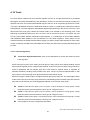
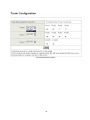
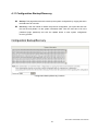
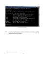
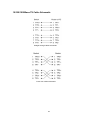
1
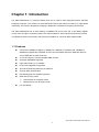
Ether-FSH2422W 24+2G Web Management Switch User’s Manual Declaration of Conformity We, Manufacturer/Importer OvisLink Corp. 5F., NO.6, Lane 130, Min-Chuan Rd., Hsin-Tien City, Taipei County, Taiwan Declare that the product 24+2 ports Mixed Gigabit Combo Web Management Switch AirLive Ether-FSH2422W is in conformity with In accordance with 89/336 EEC-EMC Directive and 1999/5 EC-R & TTE Directive Clause Description ■ EN Limits and methods of measurement of radio disturbance characteristics of information technology equipment 55022:2006 ■ EN 61000-3-2:2000/ A2:2005 Disturbances in supply systems caused by household appliances and similar electrical equipment "Harmonics" ■ EN Disturbances in supply systems caused by household appliances and similar electrical equipment "Voltage fluctuations" ■ EN Information Technology equipment-Immunity characteristics-Limits And methods of measurement 61000-3-3:1995/ A1:2001/A2:2005 55024:1998/A1 :2001/A2:2003 ■ CE marking Manufacturer/Importer Signature : Name : Position/ Title: Albert Yeh Vice President (Stamp) Date: 2008/2/14 AirLive Ether-FSH2422W CE Declaration Statement Country cs Česky [Czech] Declaration OvisLink Corp. tímto prohlašuje, že tento AirLive Ether-FSH2422W je ve shodě se základními požadavky a dalšími příslušnými ustanoveními směrnice 1999/5/ES. da Undertegnede OvisLink Corp. erklærer herved, Dansk [Danish] at følgende udstyr AirLive Ether-FSH2422W overholder de væsentlige krav og øvrige relevante krav i direktiv 1999/5/EF. de Hiermit erklärt OvisLink Corp., dass sich das Deutsch Gerät AirLive Ether-FSH2422W in [German] Übereinstimmung mit den grundlegenden Anforderungen und den übrigen einschlägigen Bestimmungen der Richtlinie 1999/5/EG befindet. et Käesolevaga kinnitab OvisLink Corp. seadme Eesti [Estonian] AirLive Ether-FSH2422W vastavust direktiivi 1999/5/EÜ põhinõuetele ja nimetatud direktiivist tulenevatele teistele asjakohastele sätetele. en Hereby, OvisLink Corp., declares that this AirLive English Ether-FSH2422W is in compliance with the essential requirements and other relevant provisions of Directive 1999/5/EC. es Por medio de la presente OvisLink Corp. declara Español que el AirLive Ether-FSH2422W cumple con los [Spanish] requisitos esenciales y cualesquiera otras disposiciones aplicables o exigibles de la Directiva 1999/5/CE. el ΜΕ ΤΗΝ ΠΑΡΟΥΣΑ OvisLink Corp. ΔΗΛΩΝΕΙ Ελληνική [Greek] ΟΤΙ AirLive Ether-FSH2422W ΣΥΜΜΟΡΦΩΝΕΤΑΙ ΠΡΟΣ ΤΙΣ ΟΥΣΙΩΔΕΙΣ ΑΠΑΙΤΗΣΕΙΣ ΚΑΙ ΤΙΣ ΛΟΙΠΕΣ ΣΧΕΤΙΚΕΣ ΔΙΑΤΑΞΕΙΣ ΤΗΣ ΟΔΗΓΙΑΣ 1999/5/ΕΚ. fr Par la présente OvisLink Corp. déclare que Français [French] l'appareil AirLive Ether-FSH2422W est conforme aux exigences essentielles et aux autres dispositions pertinentes de la directive 1999/5/CE it Con la presente OvisLink Corp. dichiara che Italiano [Italian] questo AirLive Ether-FSH2422W è conforme ai requisiti essenziali ed alle altre disposizioni pertinenti stabilite dalla direttiva 1999/5/CE. lv Ar šo OvisLink Corp. deklarē, ka AirLive EtherLatviski [Latvian] FSH2422W atbilst Direktīvas 1999/5/EK būtiskajām prasībām un citiem ar to saistītajiem noteikumiem. sv Härmed intygar OvisLink Corp. att denna AirLive Svenska Ether-FSH2422W står I överensstämmelse med [Swedish] de väsentliga egenskapskrav och övriga relevanta bestämmelser som framgår av direktiv 1999/5/EG. Country lt Lietuvių [Lithuanian] Declaration Šiuo OvisLink Corp. deklaruoja, kad šis AirLive EtherFSH2422W atitinka esminius reikalavimus ir kitas 1999/5/EB Direktyvos nuostatas. nl Hierbij verklaart OvisLink Corp. dat het toestel AirLive Nederlands [Dutch Ether-FSH2422W in overeenstemming is met de essentiële eisen en de andere relevante bepalingen van richtlijn 1999/5/EG. mt Hawnhekk, OvisLink Corp, jiddikjara li dan AirLive Malti [Maltese] Ether-FSH2422W jikkonforma mal-ħtiġijiet essenzjali u ma provvedimenti oħrajn relevanti li hemm fidDirrettiva 1999/5/EC. hu Magyar [Hungarian] pl Polski [Polish] pt Português [Portuguese] sl Slovensko [Slovenian] Az OvisLink Corporation kijelenti, hogy az AirLive Ether-FSH2422W megfelel az 1999/05/CE irányelv alapvető követelményeinek és egyéb vonatkozó rendelkezéseinek. Niniejszym OvisLink Corp oświadcza, że AirLive Ether-FSH2422W jest zgodny z zasadniczymi wymogami oraz pozostałymi stosownymi postanowieniami Dyrektywy 1999/5/EC. OvisLink Corp declara que este AirLive EtherFSH2422W está conforme com os requisitos essenciais e outras disposições da Directiva 1999/5/CE. OvisLink Corp izjavlja, da je ta AirLive EtherFSH2422W v skladu z bistvenimi zahtevami in ostalimi relevantnimi določili direktive 1999/5/ES. sk OvisLink Corp týmto vyhlasuje, že AirLive EtherSlovensky [Slovak] FSH2422W spĺňa základné požiadavky a všetky príslušné ustanovenia Smernice 1999/5/ES. fi Suomi [Finnish] OvisLink Corp vakuuttaa täten että AirLive EtherFSH2422W tyyppinen laite on direktiivin 1999/5/EY oleellisten vaatimusten ja sitä koskevien direktiivin muiden ehtojen mukainen Hér með lýsir OvisLink Corp yfir því að AirLive EtherÍslenska [Icelandic] FSH2422W er í samræmi við grunnkröfur og aðrar kröfur, sem gerðar eru í tilskipun 1999/5/EC. no OvisLink Corp erklærer herved at utstyret AirLive Norsk [Norwegian] Ether-FSH2422W er i samsvar med de grunnleggende krav og øvrige relevante krav i direktiv 1999/5/EF. A copy of the full CE report can be obtained from the following address: OvisLink Corp. 5F, No.6 Lane 130, Min-Chuan Rd, Hsin-Tien City, Taipei, Taiwan, R.O.C. This equipment may be used in AT, BE, CY, CZ, DK, EE, FI, FR, DE, GR, HU, IE, IT, LV, LT, LU, MT, NL, PL, PT, SK, SI, ES, SE, GB, IS, LI, NO, CH, BG, RO, TR FCC Warning This Equipment has been tested and found to comply with the limits for a Class-A digital device, pursuant to Part 15 of the FCC rules. These limits are designed to provide reasonable protection against harmful interference in a residential installation. This equipment generates, uses, and can radiate radio frequency energy. It may cause harmful interference to radio communications if the equipment is not installed and used in accordance with the instructions. However, there is no guarantee that interference will not occur in a particular installation. If this equipment does cause harmful interference to radio or television reception, which can be determined by turning the equipment off and on, the user is encouraged to try to correct the interference by one or more of the following measures: Reorient or relocate the receiving antenna. Increase the separation between the equipment and receiver. Connect the equipment into an outlet on a circuit different from that to which the receiver is connected. Consult the dealer or an experienced radio/TV technician for help. CE Mark Warning This is a Class-A product. In a domestic environment this product may cause radio interference in which case the user may be required to take adequate measures. AirLive Ether-FSH2422W User’s Manual 2 TABLE OF CONTENT CHAPTER 1: INTRODUCTION ............................................................. 1 1-1 Features ........................................................................................ 1 1-2 Package Contents......................................................................... 2 CHAPTER 2: HARDWARE DESCRIPTION .......................................... 3 2-1 Physical Dimensions ..................................................................... 3 2-2 Front Panel ................................................................................... 3 2-3 LED Indicators .............................................................................. 4 2-3-1 Gigabit port LED Indicator ...................................................... 5 2-4 Rear Panel .................................................................................... 5 2-5 Desktop Installation....................................................................... 6 2-5-1 Attaching Rubber Pads ........................................................... 6 2-6 Rack-mounted Installation ............................................................ 6 2-7 Power On ...................................................................................... 6 CHAPTER 3: NETWORK APPLICATION ............................................. 7 3-1 Small Workgroup .......................................................................... 7 3-2 Segment Uplink............................................................................. 8 CHAPTER 4: WEB-BASED MANAGEMENT ....................................... 9 4-1 About Web-based Management ................................................... 9 4-2 User Login................................................................................... 10 4-3 Main Page ................................................................................... 10 4-4 Administrator ............................................................................... 11 4-4-1 Authentication Configuration................................................. 11 4-4-2 System IP Configuration ....................................................... 12 4-4-3 System Status ...................................................................... 13 4-4-4 Default Switch Setting and Reboot ....................................... 14 4-5 Port Management ....................................................................... 15 4-5-1 Port Configuration ................................................................. 15 4-5-2 Port Mirroring ........................................................................ 17 4-5-3 Bandwidth Control ................................................................ 18 4-5-4 Broadcast Storm Control ...................................................... 20 4-6 VLAN Setting .............................................................................. 21 4-6-1 VLAN Member Setting (Port Based) ..................................... 21 4-6-2 VLAN Mode .......................................................................... 23 4-6-3 VLAN PVID Index Setting ..................................................... 25 4-7 Per Port Counter ......................................................................... 27 4-8 QoS Setting................................................................................. 29 4-8-1 Priority Mode ........................................................................ 30 4-8-2 Class of Service Configuration ............................................. 31 4-9 Security Filter .............................................................................. 33 4-10 Trunk ......................................................................................... 34 4-10-1 Trunk Configuration ............................................................ 34 4-10-2 Aggregation Information ..................................................... 36 4-11 Configuration Backup/Recovery ............................................... 37 4-12 Firmware Update ...................................................................... 38 4-13 Reboot ...................................................................................... 41 4-14 Logout ....................................................................................... 42 CHAPTER 5: TROUBLESHOOTING .................................................. 43 5-1 Incorrect connections .................................................................. 43 5-2 Diagnosing LED Indicators ......................................................... 44 CHAPTER 6: TECHNICAL SPECIFICATION ..................................... 45 APPENDIX ........................................................................................... 47 10 /100BASE-TX Pin outs ................................................................. 47 10/100Base-TX Cable Schematic ..................................................... 47 10/100/1000Base-TX Pin outs .......................................................... 48 10/100/1000Base-TX Cable Schematic ............................................ 49 AirLive Ether-FSH2422W User’s Manual 2 Chapter 1: Introduction The Ether-FSH2422W is a multi-port Switch that can be used to build high-performance switched workgroup networks. This switch is a store-and-forward device that offers low latency for high-speed networking. The switch is targeted at workgroup, department or backbone computing environment. The Ether-FSH2422W has 24 auto-sensing 10/100Base-TX RJ-45 ports and 2 auto-detect Gigabit combo ports for higher connection speed. This switch features a store-and-forward switching scheme. This allows the switch to auto-learn and store source address in a 4K-entry MAC address table. 1-1 Features Conforms to IEEE802.3 10Base-T, IEEE802.3u 100Base-TX, IEEE802.3ab 1000Base-T, IEEE802.3z Gigabit fiber, IEEE802.3x Flow control and Back pressure, IEEE 802.3ad Port Trunk, IEEE 802.1p Class of Service. 24 10/100 TX plus 2 10/100/1000/Mini-GBIC Combo Automatic MDI/MDIX supported High Switch Fabric up to 8.8Gbps N-way Auto-Negotiation supported Store-and-Forwarding Switching Architecture 4K-entry MAC address table Non-Blocking full wire speed architecture IEEE 802.3x Flow control: ¾ Pause-frame for full duplex mode ¾ Back-pressure for half duplex mode Fan free design AirLive Ether-FSH2422W User’s Manual 1 1-2 Package Contents Unpack the contents of the Ether-FSH2422W and verify them against the checklist below : 24 10/100TX + 2 10/100/1000T/Mini-GBIC Combo Web Smart Switch Mounting Plate Power Cord Four Rubber Pads QIG CD Compare the contents of the Ether-FSH2422W package with the standard checklist above. If any item is missing or damaged, please contact the local dealer for exchanging. AirLive Ether-FSH2422W User’s Manual 2 Chapter 2: Hardware Description This section mainly describes the hardware of the Ether-FSH2422W and gives a physical and functional overview on the certain switch. 2-1 Physical Dimensions The Ether-FSH2422W physical dimensions is 440mm x 120mm x 44mm (W x D x H). 2-2 Front Panel The front panel of the 24 10/100TX + 2 10/100/1000T/Mini-GBIC Combo Web Smart Switch consists of 24 x 10/100Base-TX RJ-45 ports (Auto MDI/MDIX) and 2 auto-detect Giga ports which could be Copper Gigabit port or Mini-GBIC Fiber module (optional). The LED Indicators are also located on the front panel of the switch. The Front panel of Ether-FSH2422W RJ-45 Ports (Auto MDI/MDIX): 24 x 10/100 N-way auto-sensing for 10Base-T or 100Base-TX connections. In general, MDI means connecting to another Hub or Switch while MDIX means connecting to a workstation or PC. Therefore, Auto MDI/MDIX would allow connecting to another Switch or workstation without changing non-crossover or crossover cabling. 2 Giga port: The traditional RJ-45 ports can be used for up-linking wide-band paths in short distance (<100m), or the appropriate replaceable mini-GBIC ports can be used for the AirLive Ether-FSH2422W User’s Manual 3 application of wideband up-linking and long distance transmissions to fit the flexible field request. [NOTE] When the Mini-GBIC slot and the corresponding RJ-45 port are both being connected, the Mini-GBIC (Giga fiber) port has higher priority. 2-3 LED Indicators The LED Indicators display real-time information of systematic operation status. The following table provides descriptions of LED status and their meaning. LED Status Description Green Power On Off Power is not connected Green The port works in 10/100 Full-duplex mode Power Blinks (continuously) Act/Duplex Networking is active Blinks (off for about 2 seconds and on The port works in 10/100 Half-duplex mode alternatively) Off No device attached Amber The port works at speed of 100Mbps Blinks The port works at speed of 10Mbps Speed The Description of LED Indicators AirLive Ether-FSH2422W User’s Manual 4 2-3-1 Gigabit port LED Indicator The following table provides descriptions of Gigabit ports’ LEDs status and their meaning. LED Status Description Green The port works in 10/100 Full-duplex or gigabit mode Blinks (continuously) Act/Duplex Networking is active Blinks (off for about 2 seconds and on The port works in 10/100 Half-duplex mode alternatively) Off No device attached Green The port works at speed of 1000Mbps Blinks The port works at speed of 100Mbps Speed The Descriptions of Gigabit port LED Indicators 2-4 Rear Panel The 3-pronged power plug is located at the rear panel of the Ether-FSH2422W shown below. The switch will work with AC in the voltage range between 100 and 240V and Frequency of 50-60Hz. AC INPUT 100-240VAC 50/ 60Hz 0.8A MAX Power The Rear Panel of Ether-FSH2422W 5 2-5 Desktop Installation Set the switch on a sufficiently large flat space with a power outlet nearby. The surface where the user put the switch should be clean, smooth, level and sturdy. Make sure there is enough clearance around the switch to allow attachment of cables, power cord and allow air circulation. 2-5-1 Attaching Rubber Pads A. Make sure mounting surface on the bottom of the switch is grease and dust free. B. Remove adhesive backing from your Rubber Pads. C. Apply the Rubber Pads to each corner on the bottom of the switch. These footpads can prevent the switch from shock/vibration. 2-6 Rack-mounted Installation The Ether-FSH2422W comes with a rack-mounted kit and can be mounted in an EIA standard size, 19-inch Rack. The switch can be placed in a wiring closet with other equipment. Perform the following steps to rack mount the switch: A. Position one bracket to align with the holes on one side of the switch and secure it with the smaller bracket screws. Then attach the remaining bracket to the other side of the switch. B. After having attached mounting brackets, position the Ether-FSH2422W in the rack by lining up the holes in the brackets with the appropriate holes on the rack. Secure the switch to the rack with a screwdriver and the rack-mounting screws. [NOTE] For proper ventilation, it allows about at least 4 inches (10 cm) of clearance on the front and 3.4 inches (8 cm) on the back of the Switch. This is especially important for enclosed rack installation. 2-7 Power On Connect the power cord to the power socket on the rear panel of the Switch. The other side of power cord connects to the power outlet. The internal power supply of the Switch works with voltage in the range of 100-240VAC and Frequency of 50~60Hz. Check the power indicator on the front panel to see if power is properly supplied. AirLive Ether-FSH2422W User’s Manual 6 Chapter 3: Network Application This section provides you a few samples of network topology in which the switch is used. In general, Ether-FSH2422W is designed as a segment switch which with its large address table (4k MAC address) and high performance, it is ideal for interconnecting networking segments. PC, workstations, and servers can communicate each other by directly connecting with Ether-FSH2422W. The switch automatically learns nodes address, which are subsequently used to filter and forward all traffic based on the destination address. By using Uplink port, the switch can connect with another switch or hub to interconnect other small-switched workgroups to form a larger switched network. Meanwhile, the user can also use fiber ports to connect switches. The distance between two switches by connecting with fiber cable can be up to 550 m (multi-mode fiber) or 10 kilometer (single-mode fiber). 3-1 Small Workgroup The Ether-FSH2422W can be used as a standalone switch to which personal computers, server, printer server, are directly connected to form a small workgroup. 7 3-2 Segment Uplink In the illustration below, two Ethernet switches (with PCs, print server, and local server attached) are connected via 1000-FX or 10/100/1000Base-TX cable. All the devices in this network can communicate with each other through the switches. Connecting servers to the switch allows other users to access the data on server. AirLive Ether-FSH2422W User’s Manual 8 Chapter 4: Web-Based Management This section introduces the configuration and functions of the Web-Based management. 4-1 About Web-based Management An embedded HTML web site resides in flash memory on the CPU board of the switch. It offers advanced management features and allows users to manage the switch from anywhere on the network through a standard browser such as Microsoft Internet Explorer. The Web-Based Management supports Internet Explorer 6.0. It is based on Java Applets with an aim to reduce network bandwidth consumption, enhance access speed and present an easy viewing screen. The Web management only allows one person to log in at the same time. With the first user logging, the system will force him to be logged out when the second user tries to log in the system. AirLive Ether-FSH2422W User’s Manual 9 4-2 User Login 1. Launch the Internet Explorer. 2. Key in ‘http://192.168.10.1’ and the IP address assigned to the Ether-FSH2422W. Then, press “Enter”. 3. The login screen appears. 4. Key in ID & Password. The default login ID and password are “airlive”. 5. Click “OK”, then the main page of the Web-based management appears. Login page of Ether-FSH2422W 4-3 Main Page Main Page of Ether-FSH2422W AirLive Ether-FSH2422W User’s Manual 10 4-4 Administrator Administrator includes Authentication Configuration, System IP Configuration, System Status, and Load Default Setting. 4-4-1 Authentication Configuration Change web management login user name and password for the management security issue. 1. Username: Type in the new user name (The default value is ‘airlive’). 2. Password: Type in the new password (The default value is ‘airlive’). 3. Confirm password: Re-type the new password. 4. And then, click Apply . 5. User Authentication Configuration interface AirLive Ether-FSH2422W User’s Manual 11 4-4-2 System IP Configuration User can configure the IP Settings and DHCP client function in here. IP Address: Manually assign the IP address that the network is using. If DHCP function is enabled, the user doesn’t need to assign the IP address. And, the network DHCP server will assign the IP address displaying in this column for the switch. The default IP is 192.168.10.1. Subnet Mask: Assign the subnet mask to the IP address. If DHCP function is enabled, and then the user does not need to assign the subnet mask. Gateway: Assign the network gateway for the Ether-FSH2422W. The default gateway is empty. IP Configure: Select the IP addressing mode—Static or DHCP. With Static mode, the user has to fill in IP address, Subnet Mask and Gateway in the fields respectively. When the radio button of DHCP is selected, the switch will be assigned an IP address from the network DHCP server. The default IP address will be replaced by the assigned IP address on DHCP server. Click the Update button to apply the setting. System IP Configuration interface AirLive Ether-FSH2422W User’s Manual 12 4-4-3 System Status This page displays the information about the switch’s MAC address, how many ports it has, system version and kernel version. Besides, users can also fill in up to 12 characters in the Comment field for note. MAC Address: Displays the unique hardware address assigned by manufacturer (default). Number of Ports: Displays how many ports there are in the switch. Comment: Users can fill in up to 12 characters in this field. Click the Update button to save the comments. System Version: Displays the switch’s firmware version Kernel Version: Displays the kernel version And than, click Apply button. System Status interface AirLive Ether-FSH2422W User’s Manual 13 4-4-4 Default Switch Setting and Reboot Reset switch to default configuration. Click Default to reset all configurations to the default value. Factory Default interface When you see the information as below, close the web window and launch again after a while. Reboot in progress AirLive Ether-FSH2422W User’s Manual 14 4-5 Port Management Port Management includes Port Configuration, Port Mirroring, Bandwidth Control, and Broadcast Storm Control. 4-5-1 Port Configuration In Port Configuration, you can set and view the operation mode for each port. Auto-Negotiation: Enable and Disable. Being set as ‘Enable’, the Speed, Duplex mode, Pause, Backpressure, TX Capability and Address Learning are negotiated automatically. When you set it as ‘Disable’, you have to assign those items manually. Speed: When the Auto-Negotiation column is set as Disable, users have to set the connection speed to the ports ticked. Duplex: When the Auto-Negotiation column is set as Disable, users have to set the connection mode in Half/Full to the ports ticked. Pause: Flow Control for connection at speed of 10/100Mbps in Full-duplex mode. Backpressure: Flow Control for connection at speed of 10/100Mbps in Half-duplex mode. TX Capability: When the Auto-Negotiation column is set as Disable, users have to set this column as Enable or Disable. Addr. Learning: When the Auto-Negotiation column is set as Disable, users have to set this column as Enable or Disable. Select Port No.: Tick the check boxes beside the port numbers being set. Click Update to have the configuration take effect. Current Status: Displays current port status. Setting Status: Displays current. Click Update to make the configuration effective. AirLive Ether-FSH2422W User’s Manual 15 Port Configuration interface AirLive Ether-FSH2422W User’s Manual 16 4-5-2 Port Mirroring The Port mirroring is a method for monitoring traffic in switched networks. That Traffic through ports can be monitored by any of the ports means traffic goes in or out monitored (source) ports will be duplicated into mirroring (destination) port. Port Mirroring interface Dest Port: Tick the check boxes beneath the port number label to be the destination (mirroring) port for monitoring Rx only, Tx only or both RX and TX traffic which come from the source port. Users can connect the mirroring port to LAN analyzer or Netxray. Monitored Pckets: Pull down the selection menu to choose what kind of packet is to be monitored. Source Port: The ports that the user wants to monitor. All monitored port traffic will be copied to mirroring (destination) port. Users can select multiple source ports by ticking the check boxes beneath the port number label to be monitored. And then, click Update to have the configuration take effect. AirLive Ether-FSH2422W User’s Manual 17 4-5-3 Bandwidth Control You can set up every port’s frame limitation type and bandwidth rate. Bandwidth Control interface Speed Base: Pull down the selection menu item to choose the speed base in low or high mode. As the picture shows, Port No: Pull down the selection menu to choose a port to be configured. AirLive Ether-FSH2422W User’s Manual 18 Tx Rate: Pull down the selection menu to choose the transmitting rate. When Speed Base is set as Low, the transmitting rate for all the ports is in the range between 32K bytes and 8M bytes. When Speed Base is set as High, the transmitting rate for port 1 ~ 24 is in the range between 256K bytes and 64M bytes; the transmitting rate for port 25 & 26 is in the range between 2M bytes and 510M bytes. Rx Rate: Pull down the selection menu to choose the receiving rate. When Speed Base is set as Low, the receiving rate for all the ports is in the range between 32K bytes and 8M bytes. When Speed Base is set as High, the transmitting rate for port 1 ~ 24 Is in the range between 256K bytes and 64N bytes; the receiving rate for port 25 & 26 is in the range between 2M bytes and 765M bytes. And then, click Update to make the settings taken effect. 19 4-5-4 Broadcast Storm Control The switch implements a broadcast storm control mechanism. Tick the check boxes to have them beginning to drop incoming broadcast packets if the received broadcast packet counts reach the threshold defined. Each port’s broadcast storm protection function can be enabled individually by ticking the check boxes. Broadcast Storm Control interface Threshold: Type in the threshold in the range between 1 and 63 to limit the maximum byte counts, which a port can send or receive in a period of time. Enable Port: Having ticked the boxes, the port will stop transmitting or receiving data when their sending byte counts or receiving byte counts reach the defined threshold. Click Update to have the configuration take effect. AirLive Ether-FSH2422W User’s Manual 20 4-6 VLAN Setting A Virtual LAN (VLAN) is a logical network grouping that limits the broadcast domain, which would allow you to isolate network traffic, so only the members of the same VLAN will receive traffic from the ones of the same VLAN. Basically, creating a VLAN from a switch is logically equivalent of reconnecting a group of network devices to another Layer 2 switch. However, all the network devices are still plugged into the same switch physically. 4-6-1 VLAN Member Setting (Port Based) The switch provides port based VLAN configuration. Users can enable the function via VALN member setting. That is a set of ports allowed to be forwarded from the source port. The overall number of VLAN groups that this switch can support is 26. VLAN Entry No.: Pull down the selection menu item and choose a number to define a VLAN. Read: Users might want to edit an existent VLAN by selecting the VLAN number and then click read button to display the member ports of the VLAN. Dest PORT: The label of each port. Select: Tick the check boxes to have the ports being the members of the VLAN. Click Update to have the configuration take effect. VLAN MEMBER: Displays the member ports for all the ports. AirLive Ether-FSH2422W User’s Manual 21 VLAN Member Setting (Port Based) interface AirLive Ether-FSH2422W User’s Manual 22 4-6-2 VLAN Mode Tagged-based VLAN is an IEEE 802.1Q specification standard. Therefore, it is possible to create a VLAN across devices from different switch venders. IEEE 802.1Q VLAN uses a technique to insert a “tag” into the Ethernet frames. Tag contains a VLAN Identifier (VID) that indicates the VLAN numbers. Please notice that this page is only for Tag Based VLAN. VLAN Mode interface VLAN Mode: Displays VLAN mode. UplinkPort/Tag Mode: There are four radio buttons—Uplink, AddTag, don’t care, and RemoveTag—for selecting. ¾ Uplink: In normal operation, if the destination and source are located in different VLANs, the packets will be dropped. Having ticked the radio button, the port is configured as an AirLive Ether-FSH2422W User’s Manual 23 up-link port which is used in an application such as virus check or firewall. For example, the two up-link ports are located in different VLANs and are connected to a virus check station or firewall. The virus check station or firewall will check whether the packet contains the virus pattern. If not containing the virus pattern, this packet will be forwarded to the up-link port located in different VLANs. ¾ AddTag: A tag port always adds a tag to a forwarded packet with VID selected by PVID. ¾ Don’t care: If the NIC of a PC doesn’t support 802.1Q VLAN tagging, select this radio button to ignore the packets tagged. ¾ RemoveTag: An un-tagged port always removes a tag from a forwarded packet. AirLive Ether-FSH2422W User’s Manual 24 4-6-3 VLAN PVID Index Setting The switch supports a 32-entry VLAN table to provide 32 active VLANs out of 4096 VLANs defined in IEEE802.1Q. User can define 32 VID entries in the VID table and enable the tag VLAN function. When a tagged packet is received, the switch compares the VID field in the packet with the ones defined in the VID table. If it is not matched, the switch drops the packet. If it is matched, the switch uses the corresponding index to select one of the 32-entry in the VLAN table as an output port mask. That is, a set of ports, to which the packet can be forwarded to. The switch forwards the packet according to MAC address and the output port mask. If the source port is not one of the members in the VLAN table entry, the switch drops the packet. When an un-tagged packet is received, the switch uses the default PVID for the source port as index to the VID of the packet. The switch forwards the packet in the same way as mentioned above. Port: Labeled as the port number. PVID Index (1 ~ 32): Define the index of PVID. AirLive Ether-FSH2422W User’s Manual 25 VLAN PVID Index Setting interface AirLive Ether-FSH2422W User’s Manual 26 4-7 Per Port Counter This page displays the statistics of each port. Four counter categories—Receive Packet & Transmit Packet, Collision Count & Transmit Packet, Drop Packet & Receive Packet, and CRC error Packet & Receive Packet—are available to be chosen. Receive Packet & Transmit Packet: Displays the counts of received and transmitted packets of each port. Collision Count & Transmit Packet: Displays the counts of collision occurred and the counts of transmitted packets. Drop Packet & Receive Packet: Displays the counts of dropped and received packets. CRC error Packet & Receive Packet: Displays the counts of CRC error occurred and received packets. AirLive Ether-FSH2422W User’s Manual 27 Per Port Counter interface AirLive Ether-FSH2422W User’s Manual 28 4-8 QoS Setting Here you can configure QoS policy priority mode and CoS (Class of Service) configuration. QoS (Quality of Service) refers to mechanisms in the network software that make the actual determination of which packets have priority. CoS refers to feature sets, or groups of services, that are assigned to users based on company policy. If a feature set includes priority transmission, then CoS winds up being implemented in QoS functions within the routers and switches in the network. In an enterprise network, class of service (CoS) differentiates high-priority traffic from lower-priority traffic. Tags may be added to the packets to identify such classes, but they do not guarantee delivery as do quality of service (QoS) functions, which are implemented in the network devices. AirLive Ether-FSH2422W User’s Manual 29 4-8-1 Priority Mode There are three priority modes available to specify the priority of packets being serviced. Those include First-In-First-Out, All-High-Before-Low, and Weight-Round-Robin. First-In-First-Out: Packets are placed into the queue and serviced in the order they were received. All-High-Before-Low: The packets of low weight will be serviced after all of the packets of high weight are serviced. Weight-Round-Robin: All queues are serviced round-robin: a packet from one queue, a packet from the next and so on. Similar to round-robin, WRR (Weight-Round-Robin) means packets are accessed round-robin style, but weight can be given priorities. For example, four packets from a high weight might be serviced, followed by two from a low weight. Select the priority mode by click the radio button beside the mode name and click Update to have the configuration take effect. Priority Mode interface AirLive Ether-FSH2422W User’s Manual 30 4-8-2 Class of Service Configuration Class of Service (CoS) is a 3-bit field within a layer two Ethernet frame header using IEEE 802.1Q. Class of Service (CoS) is a way of managing traffic in a network by grouping similar types of traffic (for example, e-mail, streaming video, voice, large document file transfer) together and treating each type as a class with its own level of service priority. Unlike Quality of Service (QoS) traffic management, Class of Service technologies do not guarantee a level of service in terms of bandwidth and delivery time; they offer a "best-effort." Enable High Priority: When this check box is ticked, the packets passing through the following ports will be serviced in accordance with the mode of Port-based or VLAN Tag-based. Port No: The label of each port. Port Base: Tick this check box to apply the priority rule to the packets passing through the ticked ports. VLAN Tag: Tick this check box to apply the priority rule to the packets passing the ticked ports by checking the 3-bit field within the frame header. AirLive Ether-FSH2422W User’s Manual 31 Class of Service Configuration interface AirLive Ether-FSH2422W User’s Manual 32 4-9 Security Filter This function provides the security which only the MAC addresses bound with the port are allowed to access it. Port No: Displays the port number being assigned the MAC addresses. MAC Address: Users can assign up to 3 MAC addresses to the port. Read: Pull down the selection bar to choose a port number and click the Read button to show the MAC addresses bound with the port or modify the MAC addresses. Select Port: Pull down the selection menu bar to choose a port number to be set. Binding: Enable or disable the binding function. Click Update to have the configuration take effect. MAC Address Filter interface AirLive Ether-FSH2422W User’s Manual 33 4-10 Trunk Port trunk allows multiple links to be bundled together and act as a single physical link for increased throughput. It provides load balancing, and redundancy of links in a switched inter-network. Actually, the link does not have an inherent total bandwidth equal to the sum of its component physical links. Traffic in a trunk is distributed across an individual link within the trunk in a deterministic method that called a hash algorithm. The hash algorithm automatically applies load balancing to the ports in the trunk. A port failure within the trunk group causes the network traffic to be directed to the remaining ports. Load balancing is maintained whenever a link in a trunk is lost or returned to service. This switch may use Port ID, Source MAC Address, Destination MAC Address, or a combination of Source MAC Address and Destination MAC Address to be the selection for Trunk Hash Algorithm. Traffic pattern on the network should be considered carefully before applying it. When a proper hash algorithm is used, traffic is kind of randomly decided to be transmitted across either link within the trunk and load balancing will be seen. 4-10-1 Trunk Configuration Trunk Hash Algorithm Selection: Click on the radio button to choose the method for trunk hash algorithm. When trunk type is set in LACP mode, the trunk group is using LACP which allows bundling several physical ports together to form a single logical channel. A port which joins an LACP trunk group has to make an agreement with its member ports first. LACP allows a network switch to negotiate an automatic bundle by sending LACP packets to the peer. LACP is a protocol implementation in OSI layer 2 which controls through which physical links the traffic will be routed. Set the trunk type in Static mode to configure the trunk group as a static one. The advantage of static mode is that a port joins the trunk group without any handshaking with its member ports. But member ports won’t know that they should be aggregated together to form a logic trunk group. Trunk 0: There are four ports—port 1 to port 4—can be involved in a trunk group. Tick at least two check boxes and select the trunk type to configure Trunk 0. Trunk 1: There are four ports—port 5 to port 8—can be involved in a trunk group. Tick at least two check boxes and select the trunk type to configure Trunk 1. Trunk 2: There are two ports—port 25 and port 26—can be involved in trunk group 2. Tick at least two check boxes and select the trunk type to configure Trunk 2. Click Update to have the configuration take effect. AirLive Ether-FSH2422W User’s Manual 34 Trunk Configuration interface 35 4-10-2 Aggregation Information Having set up the Trunk Configuration page in static mode, you will see the static trunk group information in here. Aggregation Information interface AirLive Ether-FSH2422W User’s Manual 36 4-11 Configuration Backup/Recovery Backup: This page allows the user to back up the system configuration by copying the text in the field below to a text file. Recovery: If the user wants to restore the previous configuration, just copies the text from the text file and pastes it to the system information field. Then the user has to fill in the password (login password) and click the Update button to start system configuration recovery process. Configuration Backup/Recovery interface AirLive Ether-FSH2422W User’s Manual 37 4-12 Firmware Update The firmware update function supports web and command prompt window interface for the user to update the firmware to the switch. Both the method require the user to type in the password (login password) and type again for password confirmation, then click Update to start firmware update process. Firmware Update interface Please note that the system will erase the flash at first. When the erase process is complete, the new firmware is to be updated. Erase Flash in progress interface After the flash erasing process is done, you can decide to update the firmware via web or command prompt window. First, if you decide to update firmware via the web interface, just click the browser button to locate the firmware file. Having located the target firmware file, please click the Update button to start updating firmware. AirLive Ether-FSH2422W User’s Manual 38 Updating Firmware to the flash interface After a while, the message shows as below to indicate the user that the update process is complete. Update Complete message on web As for TFTP firmware update, users can get into the command prompt window to proceed. The command prompt window can be opened by entering "cmd" (without quotes) into Start-Run or through Start-All Programs-Accessories. A black and white window (the colors can be changed) containing the command prompt will open. Type in “tftp -i 192.168.10.1 put xxx.bin” (xxx means the file name of the firmware) and press enter to update. 39 Command Prompt Window Note The system will erase the flash at first and then update the new firmware during the update process. If the update process is not finished, the web page of Firmware Update will always be displayed when the switch powers on. AirLive Ether-FSH2422W User’s Manual 40 4-13 Reboot Click Reboot to restart the switch. Reboot interface AirLive Ether-FSH2422W User’s Manual 41 4-14 Logout Having clicked on Logout item in the tree menu, the system will ask the user to make sure to log out by clicking the Accept button or clicking the Back button to return to the previous web page. Logout Confirmation AirLive Ether-FSH2422W User’s Manual 42 Chapter 5: Troubleshooting This section is intended to help the user solve the most common problems on the Ether-FSH2422W. 5-1 Incorrect connections The switch port can auto-detect straight or crossover cable when the user links switch with other Ethernet device. The RJ-45 connector should use correct UTP or STP cable. 10/100Mbps ports use 2 pairs twisted cable and Gigabit 1000T ports use 4 pairs twisted cable. If the RJ-45 connector is not correctly pinned on right position then the link will fail. For fiber connection, please notice that fiber cable mode should match the fiber module. Faulty or loose cables Look for loose or obviously faulty connections. If they appear to be OK, make sure the connections are snug. If that does not correct the problem, try a different cable. Non-standard cables Non-standard and miss-wired cables may cause numerous network collisions and other network problem, and can seriously impair network performance. A category 5-cable tester is a recommended tool for every 100Base-T network installation. Improper Network Topologies It is important to make sure that users have a valid network topology. Common topology faults include excessive cable length and too many repeaters (hubs) between end nodes. In addition, the user should make sure that the network topology contains no data path loops. Between any two ends nodes, there should be only one active cabling path at any time. Data path loops will cause broadcast storms that will severely impact the network performance. AirLive Ether-FSH2422W User’s Manual 43 5-2 Diagnosing LED Indicators To assist in identifying problems, the switch can be easily monitored through panel indicators, which describe common problems the user may encounter and where the user can find possible solutions. If the power indicator does turn on when the power cord is plugged in, the user may have a problem with power outlet, or power cord. However, if the switch powers off after running for a while check for loose power connections, power losses or surges at power outlet. If the problem still cannot be resolved, please contact the local dealer for assistance. Cabling RJ-45 ports: Use unshielded twisted-pair (UTP) or shielded twisted-pair (STP) cable for RJ-45 connections: 100Ω Category 3, 4 or 5 cable for 10Mbps connections or 100Ω Category 5 cable for 100Mbps connections. Also be sure that the length of any twisted-pair connection does not exceed 100 meters (328 feet). Gigabit port should use Cat-5 or cat-5e cable for 1000Mbps connections. The length does not exceed 100 meters. AirLive Ether-FSH2422W User’s Manual 44 Chapter 6: Technical Specification This section provides the specifications of Ether-FSH2422W. IEEE802.3 10BASE-T IEEE802.3u 100BASE-TX IEEE802.3ab 1000BASE-T Standard IEEE802.3z Gigabit fiber IEEE802.3x Flow control and Back pressure IEEE802.3ad Port Trunk IEEE802.1p Class of Service System power (Green) 10/100TX Port: LED Indicators Activity/ Duplex (Green), Speed (Amber) 10/100/1000T/Mini-GBIC Combo: Activity/ Duplex (Green), Speed (Green) 10/100TX: 24 x RJ-45 with Auto MDI/MDI-X function Connector 10/100/1000T/Mini-GBIC Combo: 2 x RJ-45 with Auto MDI/MDI-X function + 2 x 1000 SFP Sockets Switch architecture Store and Forward Back-plane 8.8Gbps with full wire speed MAC address 4K Mac with Auto Learning Flash ROM 512Kbytes Power Supply 100 ~ 240VAC, 50/60Hz AirLive Ether-FSH2422W User’s Manual 45 Power Consumption 15.4Watts (Maximum) Operating Temp. 0oC ~ 45oC Operating Humidity 10% ~ 90% (Non-condensing) Storage Temp. -40oC ~ 70oC Dimensions 440mm x 120mm x 44mm (W x D x H) EMI FCC Class A CE UL Safety cUL CE/EN60950-1 AirLive Ether-FSH2422W User’s Manual 46 Appendix 10 /100BASE-TX Pin outs With10/100BASE-TX cable, pins 1 and 2 are used for transmitting data, and pins 3 and 6 for receiving data. RJ-45 Pin Assignments Pin Number Assignment 1 Tx+ 2 Tx- 3 Rx+ 6 Rx- [NOTE] “+” and “-” signs represent the polarity of the wires that make up each wire pair. The table below shows the 10 / 100BASE-TX MDI and MDI-X port pin outs. Pin MDI-X Signal Name MDI Signal Name 1 Receive Data plus (RD+) Transmit Data plus (TD+) 2 Receive Data minus (RD-) Transmit Data minus (TD-) 3 Transmit Data plus (TD+) Receive Data plus (RD+) 6 Transmit Data minus (TD-) Receive Data minus (RD-) 10/100Base-TX Cable Schematic The following two figures show the 10/100Base-TX cable schematic. 47 Straight-through cable schematic Cross over cable schematic 10/100/1000Base-TX Pin outs The following figure shows the 10/100/1000 Ethernet RJ-45 pin outs. 48 10/100/1000Base-TX Cable Schematic Straight through cables schematic Cross over cables schematic 49