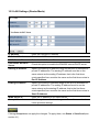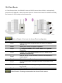
1
Long Range Wireless N Client Bridge/Access Point Model: ENH200 User Manual Version : 1.0 Table of Contents CHAPTER 1 PRODUCT OVERVIEW .......................................................................................................................7 1.1 FEATURE ..................................................................................................................................................................... 7 1.2 BENEFITS .................................................................................................................................................................... 8 1.3 PACKAGE CONTENTS ................................................................................................................................................. 9 1.3 SYSTEM REQUIREMENT ............................................................................................................................................. 9 CHAPTER 2 HARDWARE OVERVIEW.................................................................................................................. 10 CHAPTER 3 INSTALLATION .................................................................................................................................. 11 CHAPTER 4 CONFIGURING YOUR COMPUTER FOR TCP/IP........................................................................... 14 4.1 CONFIGURING MICROSOFT WINDOWS 7 ............................................................................................................................ 15 4.2 CONFIGURING MICROSOFT WINDOWS VISTA ....................................................................................................................... 17 4.3 CONFIGURING MICROSOFT WINDOWS XP .......................................................................................................................... 19 4.4 CONFIGURING MICROSOFT WINDOWS 2000 ...................................................................................................................... 20 4.5 CONFIGURING AN APPLE MACINTOSH COMPUTER ................................................................................................................ 22 CHAPTER 5 INTRODUCING THE WEB CONFIGURATOR .................................................................................................. 23 5.1 LOGGING IN TO THE WEB CONFIGURATOR ........................................................................................................................... 23 CHAPTER 6 STATUS .............................................................................................................................................. 25 6.1 SAVE/LOAD ............................................................................................................................................................... 25 6.2 MAIN ......................................................................................................................................................................... 26 6.3 WIRELESS CLIENT LIST ............................................................................................................................................ 27 6.4 SYSTEM LOG ............................................................................................................................................................ 28 6.5 CONNECTION STATUS .............................................................................................................................................. 29 6.6 DHCP CLIENT TABLE ............................................................................................................................................... 30 CHAPTER 7 SYSTEM ............................................................................................................................................. 31 7.1 CHANGING OPERATING MODES ............................................................................................................................... 31 CHAPTER 8 WIRELESS CONFIGURATION ......................................................................................................... 33 8.1 WIRELESS SETTINGS ............................................................................................................................................... 33 8.1.1 Access Point Mode ..................................................................................................................................... 33 8.1.2 Client Bridge Mode ..................................................................................................................................... 37 8.1.3 WDS Bridge Mode ...................................................................................................................................... 40 8.1.4 Client Router Mode..................................................................................................................................... 43 8.2 WIRELESS SECURITY SETTINGS .............................................................................................................................. 46 8.2.1 WEP .............................................................................................................................................................. 46 8.2.2 WPA-PSK ..................................................................................................................................................... 47 8.2.3 WPA2-PSK................................................................................................................................................... 48 8.2.4 WPA-PSK Mixed ......................................................................................................................................... 49 8.2.5 WPA .............................................................................................................................................................. 50 8.2.6 WPA2 ............................................................................................................................................................ 51 8.2.7 WPA Mixed................................................................................................................................................... 52 8.4 WIRELESS ADVANCED SETTINGS ............................................................................................................................. 53 8.5 WIRELESS MAC FILTER ........................................................................................................................................... 55 8.6 WDS LINK SETTINGS ............................................................................................................................................... 56 CHAPTER 9 LAN SETUP........................................................................................................................................ 57 9.1 IP SETTINGS ............................................................................................................................................................. 57 9.2 SPANNING TREE SETTINGS ...................................................................................................................................... 58 CHAPTER 10 ROUTER SETTINGS ....................................................................................................................... 59 10.1 WAN SETTINGS ..................................................................................................................................................... 59 10.1.1 Static IP ...................................................................................................................................................... 59 10.1.2 DHCP (Dynamic IP).................................................................................................................................. 61 10.1.3 PPPoE (Point-to-Point Protocol over Ethernet).................................................................................... 63 10.1.4 PPTP (Point-to-Point Tunneling Protocol) ............................................................................................. 65 10.2 LAN SETTINGS (ROUTER MODE) .......................................................................................................................... 67 10.3 VPN PASS THROUGH ............................................................................................................................................ 68 10.4 PORT FORWARDING ............................................................................................................................................... 69 10.5 DMZ....................................................................................................................................................................... 71 CHAPTER 11 MANAGEMENT SETTINGS ............................................................................................................ 72 11.1 ADMINISTRATION..................................................................................................................................................... 72 11.2 MANAGEMENT VLAN ............................................................................................................................................. 74 11.3 SNMP SETTINGS ................................................................................................................................................... 75 11.4 BACKUP/RESTORE SETTINGS ................................................................................................................................ 76 11.5 FIRMWARE UPGRADE ............................................................................................................................................. 77 11.6 TIME SETTINGS....................................................................................................................................................... 78 11.7 LOG ......................................................................................................................................................................... 79 11.8 DIAGNOSTICS ......................................................................................................................................................... 80 CHAPTER 12 NETWORK CONFIGURATION EXAMPLES .................................................................................. 81 12.1 ACCESS POINT ....................................................................................................................................................... 81 12.2 CLIENT BRIDGE MODE ........................................................................................................................................... 82 12.3 WDS BRIDGE MODE.............................................................................................................................................. 84 12.4 CLIENT ROUTER ..................................................................................................................................................... 85 CHAPTER 13 BUILDING A WIRELESS NETWORK............................................................................................. 86 13.1 ACCESS POINT MODE ............................................................................................................................................ 86 13.2 ACCESS POINT MODE WITH WDS FUNCTION ....................................................................................................... 87 13.3 CLIENT BRIDGE MODE ........................................................................................................................................... 88 13.4 WDS BRIDGE MODE.............................................................................................................................................. 89 13.5 CLIENT ROUTER MODE .......................................................................................................................................... 90 13.6 RADIUS CONNECTIONS........................................................................................................................................ 90 APPENDIX A – TROUBLESHOOTING ............................................................................................................................. 92 A.1 PROBLEM SOLVING ........................................................................................................................................................ 92 A.2 CONTACTING TECHNICAL SUPPORT .................................................................................................................................... 93 APPENDIX B – SPECIFICATIONS.................................................................................................................................... 94 APPENDIX C – GLOSSARY............................................................................................................................................. 95 APPENDIX D – FCC INTERFERENCE STATEMENT .......................................................................................................... 100 About This Document Audience This document is written for networking professionals responsible for installing and managing the EnGenius ENH Series Outdoor Access Point/Bridge. To use this guide, you should have knowledge about TCP/IP and IEEE 802.11 standards, and be familiar with the concepts and terminology associated with wireless local-area networks (WLANs). This document provides the information you need to install and configure your Access Point/bridge. Convention This publication uses these conventions/symbols to convey instructions and information and highlight special message. Caution: This symbol represents the important message on incorrect device operation that might damage the device Note: This symbol represents the important message for the settings. Tip: This symbol represents the alternative choice that can save time or resources. Icons used__________________________________________________ Figures in this document may use the following generic icons. EHN device Internet Power adapter WLAN signal Client computer laptop Client computer desktop PoE injector Chapter 1 Product Overview Thank you for choosing ENH200. The ENH200 is a long range, high‐performance IEEE 802.11b/g/n network solution that provides Access Point, Client Bridge, WDS, and Client Router functions in a single device. In addition to providing the latest wireless technology, the ENH200 supports Power over Ethernet and Power by Adapter capabilities, which allow the device to be installed easily in nearly any indoor or outdoor location. Advanced features include power level control, narrow bandwidth selection, traffic shaping, and Real‐time RSSI indication. A variety of security features help to protect your data and privacy while you are online. Security features include Wi‐Fi Protected Access (WPA‐PSK/WPA2‐PSK), 64/128/152‐bit WEP Encryption, and IEEE 802.1x with RADIUS. 1.1 Feature The following list summarizes the key features of the ENH200: - High-speed data rates up to 150 Mbps make the ENH200 ideally suited for handling heavy data payloads such as MPEG video streaming - High output power up to 26 dBm delivers superior range and coverage - Fully Interoperable with IEEE 802.11b/IEEE 802.11g/IEEE 802.11n-compliant devices - Multi-function capabilities enable users to use different modes in various environments - Point-to-point and point-to-multipoint wireless connectivity enable data transfers between two or more buildings - Channel bandwidth selection allows the appropriate bandwidth to be used to reach various distances - RSSI indicator makes it easy to select the best signal for Access Point connections - Power-over-Ethernet capabilities allow for flexible installation locations and cost savings - Four SSIDs let clients access different networks through a single Access Point, and assign different policies and functions for each SSID - WPA2/WPA/ WEP/ IEEE 802.1x support and MAC address filtering ensure secure network connections - PPPoE/PPTP function support make it easy to access the Internet via Internet Service Provider (ISP) service authentication - SNMP Remote Configuration Management helps administrators remotely configure or manage the Access Point - QoS (WMM) support enhances performance and user experiences 1.2 Benefits The ENH200 is the ideal product around which you can build your WLAN. The following list summarizes a few key advantages that WLANs have over wired networks: Ideal for hard‐to‐wire environments There are many scenarios where cables cannot be used to connect networking devices. Historic and older buildings, open areas, and busy streets, for example, make wired LAN installations difficult, expensive, or impossible. Temporary workgroups WLANs make it easy to provide connectivity to temporary workgroups that will later be removed. Examples include parks, athletic arenas, exhibition centers, disaster‐recovery shelters, temporary offices, and construction sites. Ability to access real‐time information With a WLAN, workers who rely on access to real‐time information, such as doctors and nurses, point‐of‐sale employees, mobile workers, and warehouse personnel, can access the data they need and increase productivity, without having to look for a place to plug into the network. Frequently changed environments WLANs are well suited for showrooms, meeting rooms, retail stores, and manufacturing sites where workplaces are rearranged frequently. Wireless extensions to Ethernet networks WLANs enable network managers in dynamic environments to minimize overhead caused by moves, extensions to networks, and other changes. Wired LAN backup Network managers can implement WLANs to provide backup for mission‐critical applications running on wired networks. Mobility within training/educational facilities Training sites at corporations and students at universities are a few examples where wireless connectivity can be used to facilitate access to information, information exchanges, and learning. 1.3 Package Contents Open the package carefully and make sure it contains all of the items listed below. ‐ One EnGenius Wireless Access Point / Client Bridge (ENH200) ‐ One 24V/0.6A power adapter ‐ One PoE injector (EPE‐24R) ‐ One mast strap ‐ One quick‐installation guide ‐ One CD containing the user manual If any item is missing or damaged, contact your place of purchase immediately. Keep all packing materials in case you need to return the ENH200. The ENH200 must be returned with its original packing materials. Use only the power adapter supplied with your ENH200. Using a different power adapter can damage the ENH200. 1.3 System Requirement To install the ENH200, you need an Ethernet cable and a computer equipped with: ‐ An Ethernet interface ‐ One of the following operating systems: Microsoft Windows XP, Vista, or 7; or Linux ‐ An Internet browser that supports HTTP and JavaScript Chapter 2 Hardware Overview The following figures show the key components on the ENH200. 2.1 Bottom View The bottom panel of the ENH200 contains two RJ‐45 ports, a PoE interface, and a Reset button. A removable cover covers these components. ‐ The RJ‐45 port connects to an Ethernet adapter in a computer you use to configure the ENH200. For more information, see Chapter 4. ‐ The PoE interface allows the ENH200 to be powered using the supplied PoE injector. ‐ The Reset button can be used to reboot the ENH200 and return the device to its default factory configuration, erasing any overrides you may have made to the device’s default settings. The Reset button is recessed to prevent accidental resets. To reboot the ENH200, use a flat object such as a pencil to press the Reset button for approximately 10 seconds and then stop pressing the Reset button. 2.2 Back Panel The back panel of the ENH200 contains the LED indicators that show the link quality and status of the ENH200. Chapter 3 Installation This chapter describes how to install the ENH200. It also describes the ENH200 LEDs. Only experienced installation professionals who are familiar with local building and safety codes and, wherever applicable, are licensed by the appropriate government regulatory authorities should install the ENH200. 3.1 Pre‐installation Guidelines Select the optimal locations for the equipment using the following guidelines: - The ENH200 should be mounted on a 1"‐4" pole. Its location should enable easy access to the - unit and its connectors for installation and testing. The higher the placement of the antenna, the better the achievable link quality. The antenna should be installed to provide a direct, or near line of sight with the Base Station antenna. The antenna should be aligned to face the general direction of the Base Station. 3.2 Installing the ENH200 To install the ENH200, use the following procedure to mount the device on a pole and refer to the figure below. 1. The bottom of the ENH200 is a movable cover. Grab the cover and pull it back hard to remove the cover. 2. Insert a standard Ethernet cable into the RJ‐45 port labeled MAIN LAN. 3. Slide the cover back to seal the bottom of the ENH200. 4. Remove the power cord and PoE injector from the box and plug the power cord into the DC port of the PoE injector. Only use the power adapter supplied with the ENH200. Using a different power adapter might damage the ENH200. 5. Plug the other side of the Ethernet cable in step 3 into the PoE port of the PoE injector. When you finish step 5, the installation will resemble the following picture. 6. Turn over the ENH200. Then insert the mast strap through the middle hole of the ENH200. Use a screwdriver to unlock the pole‐mounting ring putting it through the ENH200. 7. Mount the EOA200 securely to the pole by locking the strap tightly. This completes the installation procedure. 3.2 Understanding the ENH200 LEDs The rear of the ENH200 has two groups of LEDs. One group, labeled INDICATORS, shows the status of the device. The second group, LINK QUALITY, shows the strength of the link between the ENH200 and the network. The following table describes the ENH200 LEDs. LED Color Mode Power Green OFF= ENH200 is not receiving power. ON= ENH200 is receiving power. LAN Green OFF = ENH200 is not connected to the network. ON = ENH200 is connected to the network, but not sending or receiving data. Blink = ENH200 is sending or receiving data. WLAN Green Access Point OFF = ENH200 radio is off and the device is not or Client sending or receiving data over the wireless LAN. Bridge Mode ON = ENH200 radio is on, and the device is not sending or receiving data over the wireless LAN. Blink = ENH200 radio is on, and the device is sending or receiving data over the wireless LAN. Link Quality See Status column Access Point Shows the strength of the link between the ENH200 or Client and the network. Bridge Mode G = good quality (green). Y = medium quality (yellow). R = poor or no link (red). Status Chapter 4 Configuring Your Computer for TCP/IP To configure the ENH200, use a computer that is configured for TCP/IP. This chapter describes how to configure the TCP/IP settings on a computer that will be used to configure the ENH200. 4.1 Configuring Microsoft Windows 7 Use the following procedure to configure a computer running Microsoft Windows 7. 1. In the Start menu search box, type: ncpa.cpl 2. When the Network Connections List appears, right‐click the Local Area Connection icon and click Properties. 3. In the Networking tab, click either Internet Protocol Version 4 (TCP/IPv4) or Internet Protocol Version 6 (TCP/IPv6), and then click Properties. 4. In the properties dialog box, click Obtain an IP address automatically to configure your computer for DHCP. 5. Click the OK button to save your changes and close the dialog box. 6. Click the OK button again to save your changes. 4.2 Configuring Microsoft Windows Vista Use the following procedure to configure a computer running Microsoft Windows Vista with the default interface. If you use the Classic interface, where the icons and menus resemble previous Windows versions, perform the procedure in section 4.4. 1. On the Windows taskbar, click Start, click Control Panel, and then select the Network and Internet icon. 2. Click View Networks Status and tasks and then click Management Networks Connections. 3. Right‐click the Local Area Connection icon and click Properties. 4. Click Continue. The Local Area Connection Properties dialog box appears. 5. In the Local Area Connection Properties dialog box, verify that Internet Protocol (TCP/IPv4) is checked. Then select Internet Protocol (TCP/IPv4) and click the Properties button. The Internet Protocol Version 4 Properties dialog box appears. 6. In the Internet Protocol Version 4 Properties dialog box, click Obtain an IP address automatically to configure your computer for DHCP. 7. Click the OK button to save your changes and close the dialog box. 8. Click the OK button again to save your changes. 4.3 Configuring Microsoft Windows XP Use the following procedure to configure a computer running Microsoft Windows XP with the default interface. If you use the Classic interface, where the icons and menus resemble previous Windows versions, perform the procedure in section 4.4. 1. 2. On the Windows taskbar, click Start, click Control Panel, and then click Network and Internet Connections. Click the Network Connections icon. 3. Click Local Area Connection for the Ethernet adapter connected to the ENH200. The Local Area Connection Status dialog box appears. 4. In the Local Area Connection Status dialog box, click the Properties button. The Local Area Connection Properties dialog box appears. 5. In the Local Area Connection Properties dialog box, verify that Internet Protocol (TCP/IP) is checked. Then select Internet Protocol (TCP/IP) and click the Properties button. The Internet Protocol (TCP/IP) Properties dialog box appears. 6. In the Internet Protocol (TCP/IP) Properties dialog box, click Obtain an IP address automatically to configure your computer for DHCP. Click the OK button to save this change and close the Internet Protocol (TCP/IP) Properties dialog box. 7. Click the OK button again to save your changes. 8. Restart your computer. 4.4 Configuring Microsoft Windows 2000 Use the following procedure to configure your computer if your computer has Microsoft Windows 2000 installed. 1. On the Windows taskbar, click Start, point to Settings, and then click Control Panel. 2. In the Control Panel window, double‐click the Network and Dial‐up Connections icon. If the Ethernet adapter in your computer is installed correctly, the Local Area Connection icon appears. 3. Double‐click the Local Area Connection icon for the Ethernet adapter connected to the ENH200. The Local Area Connection Status dialog box appears. 4. In the Local Area Connection Status dialog box, click the Properties button. The Local Area Connection Properties dialog box appears. 5. In the Local Area Connection Properties dialog box, verify that Internet Protocol (TCP/IP) is checked. Then select Internet Protocol (TCP/IP) and click the Properties button. 6. Click Obtain an IP address automatically to configure your computer for DHCP. 7. Click the OK button to save this change and close the Local Area Connection Properties dialog box. 8. Click OK button again to save these new changes. 9. Restart your computer. 4.5 Configuring an Apple Macintosh Computer The following procedure describes how to configure TCP/IP on an Apple Macintosh running Mac OS 10.2. If your Apple Macintosh is running Mac OS 7.x or later, the steps you perform and the screens you see may differ slightly from the following. However, you should still be able to use this procedure as a guide to configuring your Apple Macintosh for TCP/IP. 1. Pull down the Apple Menu, click System Preferences, and select Network. 2. Verify that the NIC connected to the ENH200 is selected in the Show field. 3. In the Configure field on the TCP/IP tab, select Using DHCP. 4. Click Apply Now to apply your settings and close the TCP/IP dialog box. Chapter 5 Introducing the Web Configurator The ENH200 has a built‐in Web Configurator that lets you manage the unit from any location using a Web browser that supports HTTP and has JavaScript installed. 5.1 Logging in to the Web Configurator After configuring the computer for TCP/IP using the procedure appropriate for your operating system, use that computer’s Web browser to log in to the ENH200 Web Configurator. 1. Launch your Web browser. 2. In the browser address bar, type 192.168.1.1 and press the Enter key. If you changed the ENH200 LAN IP address, enter the correct IP address. 3. When the Windows Security window appears, type admin as the username in the top field and type admin as the password in the bottom field. 4. Click OK You are now ready to use the instructions in the following chapters to configure the ENH200. 5.2 Best Practices Perform the following procedures regularly to make the ENH200 more secure and manage the ENH200 more effectively. ‐ Change the default password. Use a password that is not easy to guess and that contains different characters, such as numbers and letters. The ENH200 username cannot be changed. For more information, see page 72. ‐ Back up the configuration and be sure you know how to restore it. Restoring an earlier working configuration can be useful if the ENH200 becomes unstable or crashes. If you forget your password, you will have to reset the ENH200 to its factory default settings and lose any customized override settings you configured. However, if you back up an earlier configuration, you will not have to completely reconfigure the ENH200. You can simply restore your last configuration. For more information, see page 76. Chapter 6 Status The Status section on the navigation drop‐down menu contains the following options: - Main - Wireless Client List - System Log - Connection Status The following sections describe these options. 6.1 Save/Load This page lets you save and apply the settings shown under Unsaved changes list, or cancel the unsaved changes and revert to the previous settings that were in effect. 6.2 Main Clicking the Main link under the Status drop-down menu or clicking Home at the top-right of the Web Configurator shows status information about the current operating mode. - The System Information section shows general system information such as operating mode, system up time, firmware version, serial number, kernel version, and application version. - The LAN Settings section shows Local Area Network setting such as the LAN IP address, subnet mask, and MAC address. - The Current Wireless Settings section shows wireless information such as frequency and channel. Since the ENH200 supports multiple-SSIDs, information about each SSID, such as its ESSID and security settings, are displayed. 6.3 Wireless Client List Clicking the Wireless Client List link under the Status drop-down menu displays the list of clients associated to the ENH200, along with the MAC addresses and signal strength for each client. Clicking the Refresh button updates (refreshes) the client list. 6.4 System Log The ENH200 automatically logs (records) events of possible interest in its internal memory. To view the logged information, click the System Log link under the Status drop-down menu. If there is not enough internal memory to log all events, older events are deleted from the log. 6.5 Connection Status Clicking the Connection Status link under the Status drop-down menu displays the current status of the network. The information shown includes network type, SSID, BSSID, connection status, wireless mode, current channel, security, data rate, noise level, and signal strength. 6.6 DHCP Client Table Clicking the DHCP Client List link under the Status drop-down menu displays the clients that are associated to the ENH200 through DHCP. The MAC addresses and signal strength for each client are also shown. Clicking the Refresh button updates (refreshes) the client list. Chapter 7 System This chapter describes how to change the ENH200 operating modes. 7.1 Changing Operating Modes The ENH200 supports four operating modes: - Access Point - Client Bridge WDS Bridge Client Router To select an operating mode, click System Properties under System Section. Then go to System > Operation mode. . Device Name: Enter a name for the device. The name you type appears in SNMP management. This name is not the SSID and is not broadcast to other devices. Country/Region: Select a Country/Region to conform to local regulations. Operation Mode: Use the radio button to select an operating mode. To use Access Point mode with WDS, select Access Point here and then enable the WDS function in the Wireless Network section (see section 8.6). Click Accept to confirm the changes. Clicking Accept does not apply the changes. To apply them, use Status > Save/Load (see section 4.1). Chapter 8 Wireless Configuration This chapter describes the ENH200’s wireless settings. Please read the information in this chapter carefully. If you configure a setting improperly, it can impact performance and affect the network adversely. Before you continue, be sure you selected the appropriate operating mode (see Chapter 7). 8.1 Wireless Settings This section describes basic wireless settings. For more information, see Chapter 12. 8.1.1 Access Point Mode The ENH200 supports Access Point Mode. In this mode, users with a wireless client device within range can connect to the ENH200 to access the WLAN. The following figure shows an example of an ENH200 operating in Access Point Mode. The sections that follow the figure below describe how to configure your ENH200 for Access Point Mode. Wireless Mode Wireless mode supports 802.11b/g/n mixed modes. Channel HT Mode The default channel bandwidth is 40 MHz. The larger the channel, the better the transmission quality and speed. Extension Channel Select upper or lower channel. Your selection may affect the Auto channel function. Channel / Frequency Select the channel and frequency appropriate for your country’s regulation. Auto Check this option to enable auto-channel selection. AP Detection AP Detection can select the best channel to use by scanning nearby areas for Access Points. Current Profile Configure up to four different SSIDs. If many client devices will be accessing the network, you can arrange the devices into SSID groups. Click Edit to configure the profile and check whether you want to enable extra SSID. Profile Isolation Restricted Client to communicate with different VID by Selecting the radio button. Accept / Cancel Click Accept to confirm the changes or Cancel to cancel and return previous settings. Clicking Accept does not apply the changes. To apply them, use Status > Save/Load (see section 4.1). SSID Specify the SSID for the current profile. VLAN ID Specify the VLAN tag for the current profile. Suppressed SSID Check this option to hide the SSID from clients. If checked, the SSID will not appear in the site survey. Station Separation Click the appropriate radio button to allow or prevent communication between client devices. Wireless Security See the Wireless Security section. Save / Cancel Click Save to accept the changes or Cancel to cancel and return previous settings. 8.1.2 Client Bridge Mode Client Bridge Mode lets you connect two LAN segments via a wireless link as though they are on the same physical network. Since the computers are on the same subnet, broadcasts will reach all machines. As a result, DHCP information generated by the server will reach all client computers as though the clients resided on one physical network. The following figure shows an example of an ENH200 communicating with an Access Point/Wireless Router, such as the EnGenius EOA7530, operating in Client Bridge Mode. The sections that follow the figure below describe how to configure your ENH200 for Client Bridge Mode. Wireless Mode Wireless mode supports 802.11b/g/n mixed modes. SSID Specify the SSID if known. This field is completed automatically if you select an Access Point in the Site Survey. Site Survey Scans nearby locations for Access Points. You can select a discovered Access Point to establish a connection. Prefer BSSID Enter the MAC address if known. If you select an Access Point in the Site Survey, this field is completed automatically. WDS Client Click the appropriate radio button to enable or disable WDS Client. Wireless Security See section 8.2 for information. Accept / Cancel Click Accept to confirm the changes or Cancel to cancel and return previous settings. Clicking Accept does not apply the changes. To apply them, use Status > Save/Load (see section 4.1). Profile If you used the Site Survey, the Web Configurator shows nearby Access Points. To connect to an Access Point, click the Access Point’s BSSID. Wireless Security See the Wireless Security section. Refresh Click Refresh to scan again. If the Access Point has been configured to suppress its SSID, the SSID section will be blank and must be completed manually. 8.1.3 WDS Bridge Mode Unlike traditional bridging. WDS Bridge Mode allows you to create large wireless networks by linking several wireless access points with WDS links. WDS is normally used in large, open areas, where pulling wires is cost prohibitive, restricted or physically impossible. The following figure shows an example of three ENH200 configured for WDS Bridge Mode communicating with each other. In this configuration, the ENH200 device on the left side of the figure behaves as a standard bridge that forwards traffic between the WDS links (links that connect to other ENH200 WDS bridges). The sections that follow the figure below describe how to configure your ENH200 for WDS Bridge Mode. Wireless Mode Wireless mode supports 802.11b/g/n mixed modes. Channel HT Mode The default channel bandwidth is 40 MHz. The larger the channel, the better the transmission quality and speed. Extension Channel Select upper or lower channel. Your selection may affect the Auto channel function. Channel / Frequency Select the channel and frequency appropriate for your country’s regulation. Accept / Cancel Click Accept to confirm the changes or Cancel to cancel and return previous settings. Clicking Accept does not apply the changes. To apply them, use Status > Save/Load (see section 4.1). MAC Address Enter the MAC address of the Access Point to which you want to extend wireless connectivity. Mode Select Disable or Enable to disable or enable WDS. Accept / Cancel Click Accept to confirm the changes or Cancel to cancel and return previous settings. 1. Clicking Accept does not apply the changes. To apply them, use Status > Save/Load (see section 4.1). 2. The Access Point to which you want to extend wireless connectivity must enter the ENH200’s MAC address into its configuration. For more information, refer to the documentation for the Access Point. Not all Access Point supports this feature. 8.1.4 Client Router Mode In Client Router Mode, you can access the Internet wirelessly with the support of a WISP. In AP Router Mode, the ENH200 can access the Internet via a cable or DSL modem. In this mode, the ENH200 can be configured to turn off the wireless network name (SSID) broadcast, so that only stations that have the SSID can be connected. The ENH200 also provides wireless LAN 64/128/152-bit WEP encryption security, WPA/WPA2, and WPA-PSK/WPA2-PSK authentication, as well as TKIP/AES encryption security. It also supports VPN pass-through for sensitive data secure transmission. The following figure shows an example of an ENH200 communicating with a Wireless ISP (WISP) Access Point in Client Router Mode. The sections that follow the figure below describe how to configure your ENH200 for Client Router Mode. Wireless Mode Wireless mode supports 802.11b/g/n mixed modes. SSID Specify the SSID if known. This field is completed automatically if you select an Access Point in the Site Survey. Site Survey Scans nearby locations for Access Points. You can select a discovered Access Point to establish a connection. Prefer BSSID Enter the MAC address if known. If you select an Access Point in the Site Survey, this field is completed automatically. Wireless Security See section 10.2. Accept / Cancel Click Accept to confirm the changes or Cancel to cancel and return previous settings. Clicking Accept does not apply the changes. To apply them, use Status > Save/Load (see section 4.1). Profile If you used the Site Survey, the Web Configurator shows nearby Access Points. To connect to an Access Point, click the Access Point’s BSSID. Wireless Security See the Wireless Security section. Refresh Click Refresh to scan again. If the Access Point has been configured to suppress its SSID, the SSID section must be completed manually. 8.2 Wireless Security Settings The Wireless Security Settings section lets you configure the EOH200’s security modes: WEP, WPA-PSK, WPA2-PSK, WPA-PSK Mixed, WPA, WPA2, and WPA Mixed. We strongly recommend you use WPA2-PSK. 8.2.1 WEP Security Mode Select WEP from the drop-down list to begin the configuration. Auth Type Select Open System or Shared. Input Type Select an input type of Hex or ASCII. Key Length Level of WEP encryption applied to all WEP keys. Choices are Select a 64/128/152-bit password lengths. Default Key Specify which of the four WEP keys the ENH200 uses as its default. Key1 Specify a password for security key index No.1. For security, each typed character is masked by a dot (). Key2 Specify a password for security key index No.2. For security, each typed character is masked by a dot (). Key3 Specify a password for security key index No.3. For security, each typed character is masked by a dot (). Key4 Specify a password for security key index No.4. For security, each typed character is masked by a dot (). 802.11n does not allow WEP/WPA-PSK/WPA-PSK TKIP security mode. The connection mode will drop from 802.11n to 802.11g. 8.2.2 WPA-PSK Security Mode Select WPA-PSK from the drop-down list to begin the configuration. Encryption Select Both, TKIP, or AES as the encryption type. • Both = uses TKIP and AES. • TKIP = automatic encryption with WPA-PSK; requires passphrase. • AES = automatic encryption with WPA2-PSK; requires passphrase. Passphrase Specify the security password. For security, each typed character is masked by a dot (). Group Key Update Interval Specify how often, in seconds, the group key changes. 802.11n does not allow WEP/WPA-PSK/WPA-PSK TKIP security mode. The connection mode will drops from 802.11n to 802.11g. 8.2.3 WPA2-PSK Security Mode Select WPA2-PSK from the drop-down list to begin the configuration. Encryption Select Both, TKIP, or AES as the encryption type. • Both = uses TKIP and AES. • TKIP = automatic encryption with WPA-PSK; requires passphrase. • AES = automatic encryption with WPA2-PSK; requires passphrase. Passphrase Specify the security password. For security, each typed character is masked by a dot (). Group Key Update Interval Specify how often, in seconds, the group key changes. 802.11n does not allow WEP/WPA-PSK/WPA-PSK TKIP security mode. The connection mode will change from 802.11n to 802.11g. 8.2.4 WPA-PSK Mixed Security Mode Select WPA-PSK Mixed from the drop-down list to begin the configuration. Encryption Select Both, TKIP, or AES as the encryption type. • Both = uses TKIP and AES. • TKIP = automatic encryption with WPA-PSK; requires passphrase. • AES = automatic encryption with WPA2-PSK; requires passphrase. Passphrase Specify the security password. For security, each typed character is masked by a dot (). Group Key Update Interval Specify how often, in seconds, the group key changes. WPA-PSK Mixed can allow multiple security modes at the same time. 802.11n does not allow WEP/WPA-PSK/WPA-PSK TKIP security mode. The connection mode will change from 802.11n to 802.11g. 8.2.5 WPA Security Mode Select WPA from the drop-down list to begin the configuration. Encryption Select Both, TKIP, or AES as the encryption type. • Both = uses TKIP and AES. • TKIP = automatic encryption with WPA-PSK. • AES = automatic encryption with WPA2-PSK. Radius Server Specify the IP address of the RADIUS server. Radius Port Specify the port number that your RADIUS server uses for authentication. Default port is 1812. Radius Secret Specify RADIUS secret furnished by the RADIUS server. Group Key Update Interval Specify how often, in seconds, the group key changes. 802.11n does not allow WEP/WPA-PSK/WPA-PSK TKIP security mode. The connection mode will drops from 802.11n to 802.11g. 8.2.6 WPA2 Security Mode Select WPA2 from the drop-down list to begin the configuration. Encryption Select Both, TKIP, or AES as the encryption type. • Both = uses TKIP and AES. • TKIP = automatic encryption with WPA-PSK. • AES = automatic encryption with WPA2-PSK. Radius Server Specify the IP address of the RADIUS server. Radius Port Specify the port number that your RADIUS server uses for authentication. Default port is 1812. Radius Secret Specify RADIUS secret furnished by the RADIUS server. Group Key Update Interval Specify how often, in seconds, the group key changes. 802.11n does not allow WEP/WPA-PSK/WPA-PSK TKIP security mode. The date rate will drop from 802.11n to 802.11g. 8.2.7 WPA Mixed Security Mode Select WPA Mixed from the drop-down list to begin the configuration. Encryption Select Both, TKIP, or AES as the encryption type. • Both = uses TKIP and AES. • TKIP = automatic encryption with WPA-PSK. • AES = automatic encryption with WPA2-PSK. Radius Server Specify the IP address of the RADIUS server. Radius Port Specify the port number that your RADIUS server uses for authentication. Default port is 1812. Radius Secret Specify RADIUS secret furnished by the RADIUS server. Group Key Update Interval Specify how often, in seconds, the group key changes. 802.11n does not allow WEP/WPA-PSK/WPA-PSK TKIP security mode. The connection mode will change from 802.11n to 802.11g. 8.4 Wireless Advanced Settings Data Rate Select a data rate from the drop-down list. The data rate affects throughput. If you select a low data rate value, for example, the throughput is reduced but the transmission distance increases. Transmit Power Lets you increase or decrease transmit power. Higher transmit power may prevent connections to the network, while the lower transmit power can prevent clients from connecting to the device. RTS/CTS Threshold Specify the threshold package size for RTC/CTS. A small number causes RTS/CTS packets to be sent more often and consumes more bandwidth. Distance Specify the distance between Access Points and clients. Longer distances may drop high-speed connections. Antenna Selection Specify the internal antenna type. Short GI Sets the time that the receiver waits for RF reflections to settle out before sampling data. Using a short (400ns) guard interval can increase throughput, but can also increase error rate in some installations due to increased sensitivity to radio-frequency reflections. Select the option that works best for your installation. Aggregation Merges data packets into one packet. This option reduces the number of packets, but increases packet sizes. Wireless Traffic Shaping Check this option to enable wireless traffic shaping. Traffic shaping regulates the flow of packets leaving an interface to deliver improved Quality of Service. Incoming Traffic Limit Specify the wireless transmission speed used for downloading. Outgoing Traffic Limit Specify the wireless transmission speed used for uploading. Accept / Cancel Click Accept to confirm the changes or Cancel to cancel and return previous settings. 1. Changing Wireless Advanced Settings may adversely affect wireless performance. Please accept all default settings, unless you are familiar with the wireless options. 2. Clicking Accept does not apply the changes. To apply them, use Status > Save/Load (see section 4.1). 8.5 Wireless MAC Filter Wireless MAC Filters are used to allow or deny network access to wireless clients according to their MAC addresses. You can manually add a MAC address to restrict the permission to access ENH200. The default setting is Disable Wireless MAC Filters. 0. ACL Mode Determines whether network access is granted or denied to clients whose MAC addresses appear in the MAC Address table on this page. Choices are Disable, Deny MAC in the list, or Allow MAC in the list. MAC Address Filter Enter the MAC address of the device. Add Click Add to add the MAC address to the MAC Address table. Apply Click Apply to apply the changes. 8.6 WDS Link Settings Using WDS Link Settings, you can create a wireless backbone link between multiple access points that are part of the same wireless network. This allows a wireless network to be expanded using multiple Access Points without the need for a wired backbone to link them, as is traditionally required. MAC Address Enter the Access Point’s MAC address to which you want to extend the wireless area. Mode Select Disable or Enable from the drop-down list. Accept / Cancel Click Accept to confirm the changes or Cancel to cancel and return previous settings. Clicking Accept does not apply the changes. To apply them, use Status > Save/Load (see section 4.1). The Access Point to which you want to extend wireless connectivity must enter the ENH200’s MAC address into its configuration. For more information, refer to the documentation for the Access Point. Not all Access Point supports this feature. Chapter 9 LAN Setup This chapter describes the ENH200 Local Area Network (LAN) settings. 9.1 IP Settings This section is only available for Non-Router Mode. IP settings lets you configure the ENH200 LAN port IP address. IP Network Setting Select whether the ENH200 IP address will use the static IP address specified in the IP Address field or be obtained automatically when the ENH200 connects to a device that has a DHCP server . IP Address Enter the IP address of the ENH200. IP Suet Mask Enter the ENH200 subnet mask. Default Gateway Enter the ENH200 default gateway. Primary DNS Enter the ENH200 primary DNS. Secondary DNS Enter the ENH200 secondary DNS. Accept / Cancel Click Accept to confirm the changes or Cancel to cancel and return previous settings. If you change the LAN IP address, you will be directed to the new IP address after you click Apply. 9.2 Spanning Tree Settings Spanning Tree Status Enable or disable the ENH200 Spanning Tree function. Bridge Hello Time Specify Bridge Hello Time, in seconds. This value determine how often the ENH200 sends hello packets to communicate information about the topology throughout the entire Bridged Local Area Network Bridge Max Age Specify Bridge Max Age, in seconds. If another bridge in the spanning tree does not send a hello packet for a long period of time, it is assumed to be dead. Bridge Forward Delay Specify Bridge Forward Delay, in seconds. Forwarding delay time is the time spent in each of the Listening and Learning states before the Forwarding state is entered. This delay is provided so that when a new bridge comes onto a busy network, it looks at some traffic before participating. Priority Specify the Priority number. Smaller number has greater priority. Accept / Cancel Click Accept to confirm the changes or Cancel to cancel and return previous settings. Clicking Accept does not apply the changes. To apply them, use Status > Save/Load (see section 4.1). Chapter 10 Router Settings This section is only available for AP Router Mode and Client Router Mode. 10.1 WAN Settings This chapter describes the ENH200 WAN settings. There are four types of WAN connections: - Static IP - DHCP - PPPoE - PPTP Please contact your ISP to find out which settings you should choose.. 10.1.1 Static IP Select Static IP for your WAN connection if your ISP provided information about which IP address, subnet mask, default gateway, primary DNS, and secondary DNS to use. Internet Connection Type Select Static IP to begin configuration of the Static IP connection. Account Name Enter the account name provided by your ISP. Domain Name Enter the domain name provided by your ISP. MTU Specify the Maximum Transmit Unit size. It is recommended you accept the default setting of Auto. Otherwise, packets will be fragmented downstream if the MTU is set too high or too low, which impacts network performance. In extreme cases, an MTU setting that is too low can prevent the ENH200 from establishing some connections. IP Address Enter the WAN port IP address. IP Subnet Mask Enter the WAN IP subnet mask. Gateway IP Address Enter the WAN gateway IP address. Primary DNS Enter the primary DNS IP address. Secondary DNS Enter the secondary DNS IP address. Discard Ping on WAN Check to Enable to recognize pings on the ENH200 WAN interface or Disable to block pings on the ENH200 WAN interface. Note: Pinging IP addresses is a common method used by hackers to test whether the IP address is valid. Blocking pings provides some extra security from hackers. Accept / Cancel Click Accept to confirm the changes or Cancel to cancel and return previous settings. Clicking Accept does not apply the changes. To apply them, use Status > Save/Load (see section 4.1). 10.1.2 DHCP (Dynamic IP) Select DHCP as your WAN connection type to obtain an IP address automatically. You will need to enter account name as your hostname and, optionally, DNS information. Internet Connection Type Select DHCP to begin configuration of the DHCP connection. Account Name Enter the account name provided by your ISP. Domain Name Enter the domain name provided by your ISP. MTU Specify the Maximum Transmit Unit size. It is recommended you accept the default setting of Auto. Otherwise, packets will be fragmented downstream if the MTU is set too high or too low, which impacts network performance. In extreme cases, an MTU setting that is too low can prevent the ENH200 from establishing some connections. Get Automatically From ISP Click this radio button to obtain the DNS automatically from the DHCP server. Use These DNS Servers Click the radio button to set up the Primary DNS and Secondary DNS servers manually. Discard Ping on WAN Check to Enable to recognize pings on the ENH200 WAN interface or Disable to block pings on the ENH200 WAN interface. Note: Pinging IP addresses is a common method used by hackers to test whether the IP address is valid. Blocking pings provides some extra security from hackers. Accept / Cancel Click Accept to confirm the changes or Cancel to cancel and return previous settings. Clicking Accept does not apply the changes. To apply them, use Status > Save/Load (see section 4.1). 10.1.3 PPPoE (Point-to-Point Protocol over Ethernet) Select Point to Point Protocol over Ethernet (PPPoE) if your ISP uses a PPPoE connection. Your ISP will provide you with a username and password. This selection is typically used for DSL services. Remove your PPPoE software from your computer, as it is not needed and will not work with your ENH200. Internet Connection Type Select PPPoE to begin configuration of the PPPoE connection. MTU Specify the Maximum Transmit Unit size. It is recommended you accept the default setting of Auto. Otherwise, packets will be fragmented downstream if the MTU is set too high or too low, which impacts network performance. In extreme cases, an MTU setting that is too low can prevent the ENH200 from establishing some connections. Login Enter the Username provided by your ISP. Password Enter the Password provided by your ISP. Service Name Enter the Service Name provided by your ISP. Connect on Demand Select the radio button to specify the maximum idle time. Internet connection will disconnect when it reach the maximum idle time, but it will automatically connect when user tries to access the network. Keep Alive Select whether to keep the Internet connection always on, or enter a redial period once the internet lose connection. Get Automatically From ISP Select whether to obtain the DNS automatically from the DHCP server. Use These DNS Servers Click the radio button to set up the Primary DNS and Secondary DNS servers manually. Discard Ping on WAN Check to Enable to recognize pings on the ENH200 WAN interface or Disable to block pings on the ENH200 WAN interface. Note: Pinging IP addresses is a common method used by hackers to test whether the IP address is valid. Blocking pings provides some extra security from hackers. Accept / Cancel Click Accept to confirm the changes or Cancel to cancel and return previous settings. Clicking Accept does not apply the changes. To apply them, use Status > Save/Load (see section 4.1). 10.1.4 PPTP (Point-to-Point Tunneling Protocol) Select PPTP as your WAN connection type if your ISP uses a Point-to-Point-Tunneling Protocol (PPTP) connection. You will need to provide the IP address, subnet mask, default gateway (optional), DNS (optional), server IP, username, and password provided by your ISP. Internet Connection Type Select PPTP to begin configuration of the PPTP connection. MTU Specify the Maximum Transmit Unit size. It is recommended you accept the default setting of Auto. Otherwise, packets will be fragmented downstream if the MTU is set too high or too low, which impacts network performance. In extreme cases, an MTU setting that is too low can prevent the ENH200 from establishing some connections. IP Address Enter the WAN port IP address. IP Subnet Mask Enter the WAN IP subnet mask. Gateway IP Address Enter the WAN gateway IP address. PPTP Server Enter the IP address of the PPTP server. Username Enter the username provided by your ISP. Password Enter the password provided by your ISP. Connect on Demand If you want the ENH200 to end the Internet connection after it has been inactive for a period of time, select this option and enter the number of minutes you want that period of inactivity to last. Keep Alive If you want the ENH200 to periodically check your Internet connection, select this option. Then specify how often you want the ENH200 to check the Internet connection. If the connection is down, the ENH200 automatically re-establishes your connection Get Automatically From ISP Obtains the DNS automatically from DHCP server. Use These DNS Servers Click the radio button to set up the Primary DNS and Secondary DNS servers manually. Discard Ping on WAN Check to Enable to recognize pings on the ENH200 WAN interface or Disable to block pings on the ENH200 WAN interface. Note: Pinging IP addresses is a common method used by hackers to test whether the IP address is valid. Blocking pings provides some extra security from hackers. Accept / Cancel Click Accept to confirm the changes or Cancel to cancel and return previous settings. Clicking Accept does not apply the changes. To apply them, use Status > Save/Load (see section 4.1). 10.2 LAN Settings (Router Mode) IP Address Enter the LAN port IP address. IP Subnet Mask Enter the LAN IP subnet mask. WINS Server IP Enter the WINS Server IP. Use Router As DHCP Server Check this option to enable the ENH200 internal DHCP server. Starting IP Address Specify the starting IP address range for the pool of allocated for private IP addresses. The starting IP address must be on the same subnet as the ending IP address; that is the first three octets specified here must be the same as the first three octets in End IP Address. Ending IP Address Specify the ending IP address range for the pool of allocated for private IP addresses. The ending IP address must be on the same subnet as the starting IP address; that is the first three octets specified here must be the same as the first three octets in Start IP Address. WINS Server IP Enter the IP address of the WINS server. Accept / Cancel Click Accept to confirm the changes or Cancel to cancel and return previous settings. Clicking Accept does not apply the changes. To apply them, use Status > Save/Load (see section 4.1). 10.3 VPN Pass Through VPN Passthrough allows a secure virtual private network (VPN) connection between two computers. Enabling the options on this page opens a VPN port and enables connections to pass through the ENH200 without interruption. PPTP Pass Through Check this option to enable PPTP pass-through mode. L2TP Pass Through Check this option to enable L2TP pass-through mode. IPSec Pass Through Check this option to enable IPSec pass-through mode. Accept / Cancel Click Accept to confirm the changes or Cancel to cancel and return previous settings. Clicking Accept does not apply the changes. To apply them, use Status > Save/Load (see section 4.1). 10.4 Port Forwarding Port forwarding can be used to open a port or range of ports to a device on your network Using port forwarding, you can set up public services on your network. When users from the Internet make certain requests on your network, the ENH200 can forward those requests to computers equipped to handle the requests. If, for example, you set the port number 80 (HTTP) to be forwarded to IP address 192.168.1.2, all HTTP requests from outside users are forwarded to 192.168.1.2. Add Entry Click Add Entry to add port forwarding rules. Accept Click Accept to confirm the changes. Clicking Accept does not apply the changes. To apply them, use Status > Save/Load (see section 4.1). Service Name Enter a name for the port forwarding rule. Protocol Select a protocol for the application: Choices are Both, TCP, and UDP. Starting Port Enter a starting port number. Ending Port Enter an ending port number. All ports numbers between the starting and ending ports will forward users to the IP address specified in the IP Address field. IP Address Enter the IP address of the server computer on the LAN network where users will be redirected. Save / Cancel Click Save to apply the changes or Cancel to return previous settings. 10.5 DMZ If you have a computer that cannot run Internet applications properly from behind the ENH200, you can allow the computer to have unrestricted Internet access. Enter the IP address of that computer as a Demilitarized Zone (DMZ) host with unrestricted Internet access. Adding a client to the DMZ may expose that computer to a variety of security risks, so use this option as a last resort. DMZ Hosting Enables or disables the ENH200 DMZ function. DMZ Address Enter an IP address of the computer that will have unlimited Internet access. Accept / Cancel Click Accept to confirm the changes or Cancel to cancel and return previous settings. Clicking Accept does not apply the changes. To apply them, use Status > Save/Load (see section 4.1). Chapter 11 Management Settings The Management section lets you configure administration, management VLAN, SNMP settings, backup/restore settings, firmware upgrade, time settings, and log settings. This chapter describes these settings. 11.1 Administration Click the Administration link under the Management menu to change the user name and password used to log on to the ENH200 Web Configurator . The default user name is admin and the default password is admin. Changing these settings protects the ENH200 configuration settings from being accessed by unauthorized users. Name Enter a new username for logging in to the Web Configurator. Password Enter a new password for logging in to the Web Configurator Confirm Password Re-enter the new password for confirmation. Remote Management Enable or disable remote management. Remote Upgrade Specify whether the ENH200 firmware can be upgraded remotely. Remote Management Port If remote management is enabled, enter the port number to be used for remote management. For example: If you specify the port number 8080, enter http://<IP address>:8080 to access the ENH200 Web Configurator. Save/Apply / Cancel Click Save/Apply to apply the changes or Cancel to return previous settings. Clicking Save/Apply changes the settings immediately. You cannot undo the action. 11.2 Management VLAN Click the Management VLAN link under the Management menu to assign a VLAN tag to the packets. A VLAN is a group of computers on a network whose software has been configured so that they behave as if they were on a separate Local Area Network (LAN). Computers on VLAN do not have to be physically located next to one another on the LAN Management VLAN ID If your network includes VLANs and if tagged packets need to pass through the Access Point, enter the VLAN ID. Otherwise, click No VLAN tag . Accept / Cancel Click Accept to confirm the changes or Cancel to cancel and return previous settings. 1. If you reconfigure the Management VLAN ID, you may lose your connection to the ENH200. Verify that the DHCP server supports the reconfigured VLAN ID and then reconnect to the ENH200 using the new IP address. 2. Clicking Accept does not apply the changes. To apply them, use Status > Save/Load (see section 4.1). 11.3 SNMP Settings Click the SNMP Settings link under the Management menu to monitor network-attached devices using the Simple Network Management Protocol (SNMP). SNMP allows messages (called “protocol data unit’s) to be sent to various parts of a network. Upon receiving these messages, SNMP-compatible devices (called agents) return data stored in their Management Information Bases. SNMP Enable/Disable Enable or disable the ENH200 SNMP function. Contact Enter the contact details of the device. Location Enter the location of the device. Community Name Enter the password for accessing the SNMP community for read-only access. Community Name Enter the password for accessing the SNMP community for read and write access. Trap Destination IP Address Enter the IP address where SNMP traps are to be sent. Trap Destination Community Name Enter the password of the SNMP trap community. Save/Apply / Cancel Click Save/Apply to apply the changes or Cancel to return previous settings. Clicking Save/Apply change the setting immediately. You cannot undo the action. 11.4 Backup/Restore Settings Click the Backup/Restore Setting link under the Management menu to save the ENH200’s current settings in a file on your local disk or load settings onto the device from a local disk. This feature is particularly convenient administrators who have several ENH200 devices that need to be configured with the same settings. This page also lets you return the ENH200 to its factory default settings. If you perform this procedure, any changes made to the ENH200 default settings will be lost. Save A Copy of Current Settings Click Backup to save the current configured settings. Restore Saved Settings from a File To restore settings that have been previously backed up, click Revert to Factory Default Settings Click this button to restore the ENH200 to its factory default settings. Browse, select the file, and click Restore. 11.5 Firmware Upgrade Click the Firmware Upgrade link under the Management menu to upgrade the firmware of the device. To perform this procedure, downloaded the appropriate firmware from your vendor. The firmware upgrade procedure can take few minutes. Do not power off the ENH200 during the firmware upgrade, as it can cause the device to crash or become unusable. The ENH200 restarts automatically after the upgrade completes. 11.6 Time Settings Click the Time Settings link under the Management menu to configure the ENH200 system time. You can enter the time manually or, to ensure accuracy, synchronize the ENH200 with Network Time Protocol (NTP) server. Manually Set Date and Time Manually specify the date and time. Automatically Get Date and Time Select a time zone from the drop-down list and check whether you want to enter the IP address of an NTP server or use the default NTP server. Save/Apply / Cancel Click Save/Apply to apply the changes or Cancel to return previous settings. Clicking Save/Apply changes the setting immediately. You cannot undo the action. 11.7 Log Click the Log link under the Management menu to display a list of events that are triggered on the ENH200 Ethernet and wireless interfaces. You can consult this log if an unknown error occurs on the system or when a report needs to be sent to the technical support department for debugging purposes. Syslog Enable or disable the ENH200syslog function. Log Server IP Address Enter the IP address of the log server. Local Log Enable or disable the local log service. Save/Apply / Cancel Click Save/Apply to apply the changes or Cancel to return previous settings. Clicking Save/Apply changes the settings immediately. You cannot undo the action. 11.8 Diagnostics Click the Diagnostics link under the Management menu to ascertain connection quality and trace the routing table to the target. Target IP Enter the IP address you would like to search. Ping Packet Size Enter the packet size of each ping. Number of Pings Enter the number of times you want to ping. Start Ping Click Start Ping to begin pinging. Traceroute Target Enter an IP address or domain name you want to trace. Start Traceroute Click Start Traceroute to begin the trace route operation. Chapter 12 Network Configuration Examples This chapter provides step-by-step descriptions for using the ENH200’s operating modes. The Access Point Mode’s default configuration allows the ENH200 to act as a central unit of a WLAN or as a root device of a wired environment. Repeater mode and Mesh network mode are reserved for future configuration. 12.1 Access Point Access Point Step1 Log in to the Web Configurator with your browser by entering the default IP address 192.168.1.1 Step2 Select your country or region’s regulation. Step3 Use site survey to scan channels available in nearby areas. Step4 Select channel with less interferences. Step5 Specify the SSID for your broadcast SSID and you can also configure multiple SSID at the same time. Step6 Verify the VLAN identifier to separate services among clients Step7 Set the authentication settings. Step8 Click Apply to save all changes. For more advanced settings, refer to the previous chapters. Wireless Client Step1 Select the wireless mode with which you want to associate. Step2 Use site survey to scan nearby Access Point and either select the Access Point to which you want to connect, or enter the SSID manually. Step3 Configure the VLAN ID in your wireless device if available. Step4 Select the appropriate authentication type and password. Access Point Mode does not provide DHCP server, so the Wireless Client IP address must be configured manually using the same Local Area Network subnet. 12.2 Client Bridge Mode Client Bridge Mode functions like a wireless dongle. It must connect to an Access Point/AP Router to join the network. Refer to Chapter 13 to check the Access Point’s configuration. Client Bridge Step1 Log in to the Web Configurator with the default IP address 192.168.1.1 Step2 Select your country or region’s regulation. Step3 For Operation Mode, select Client Bridge from System Properties. Step4 Use site survey to scan Access Points that are available in nearby areas. Step5 Select the Access Point with which you want to associate. Step6 Set up the authentication settings that match the Access Point’s settings. Step7 Click Apply to save all changes. The Client Bridge IP settings must match the Access Point’s subnet. 12.3 WDS Bridge Mode Use this feature to link multiple Access Points in a network. All clients associated with any Access Points can communicate with each other in an ad-hoc manner. WDS Bridge Step1 Log in to the Web Configurator with the default IP address 192.168.1.1 Step2 Select your country or region’s regulation. Step3 For Operation Mode, select WDS Bridge from System Properties. Step4 Select the channel you want to use. Step5 Set up the authentication settings Step6 Set up WDS Link Settings. Step7 Specify the MAC address of the Access Point with which you want to connect. Step8 Click Apply to save all changes. Each WDS bridge device must use the same Subnet, Wireless Mode, Wireless Channel, and Security Setting. 12.4 Client Router In Client Router Mode, the ENH200’s internal DHCP server allows LANs to automatically generate an IP address to share the same Internet. Connect an Access Point/WISP wirelessly and connect to LANs using a wired connection. Refer to Chapter 13 to check the Access Point’s configuration. Client Router Step1 Log in to the Web Configurator with the default IP address 192.168.1.1 Step2 Select your country or region’s regulation. Step3 For Operation Mode, select Client Router from System Properties. Step4 Change your Local Area Network setting to Obtain an IP Address Automatically. Step5 Use site survey to scan Access Points that are available in nearby areas. Step6 Select the Access Point with you want to associate. Step7 Set up authentication settings that match the Access Point’s settings. Step8 Step9 Set your WAN connection type using the WAN settings provided by your ISP. Click Apply to save all changes. Client Router’s IP setting must match to the Access Point’s subnet. Chapter 13 Building a Wireless Network With its ability to operate in various operating modes, your ENH200 is the ideal device around which you can build your WLAN. This appendix describes how to build a WLAN around your ENH200 using he device’s operating modes. 13.1 Access Point Mode In Access Point Mode, ENH200 behaves likes a central connection for stations or clients that support IEEE 802.11b/g/n networks. Stations and client must be configured to use the same SSID and security password to associate with the ENH200. The ENH200 supports four SSIDs at the same time for secure guest access. 13.2 Access Point Mode with WDS Function The ENH200 Access Point Mode also supports WDS functionality. This operating mode allows wireless connections to the ENH200 using WDS technology. In this mode, configure the MAC addresses in both Access Points to enlarge the wireless area by enabling WDS Link settings. WDS supports eight AP MAC addresses. Not every Access Point device supports WDS in Access Point Mode. As a result, to use WDS, we recommend you use the ENH200. 13.3 Client Bridge Mode In Client Bridge Mode, the ENH200 behaves like a wireless client that connects to an Access Point wirelessly and allows users to surf the Internet whenever they want. In this mode, use the ENH200 Site Survey to scan for Access Points within range. Then configure the ENH200 SSID and security password accordingly to associate with the Access Point. In this configuration, the station has a wired Ethernet connection to the ENH200 LAN port. 13.4 WDS Bridge Mode In WDS Bridge Mode, the ENH200 can wirelessly connect different LANs by configuring the MAC address and security settings of each ENH200 device. Use this mode when two wired LANs located a small distance apart want to communicate with each other. The best solution is to use the ENH200 to wirelessly connect two wired LANs, as shown in the following figure. WDS Bridge Mode can establish 16 WDS links, creating a star-like network. WDS Bridge Mode is unlike Access Point. Access Points linked by WDS are using the same frequency channel, more Access Points connected together may lower throughput. Please be aware to avoid loop in your wireless connection, otherwise enable Spanning Tree Function. 13.5 Client Router Mode In Client Router Mode, the ENH200’s internal DHCP server allows a number of LANs to automatically generate IP addresses to share the same Internet. In this mode, connect an AP/WISP wirelessly and connect to LANs via a wired connection. 13.6 RADIUS Connections Remote Authentication Dial In User Service (RADIUS) authentication is available when configuring the ENH200 wireless advanced settings (see Chapter 8). Use this feature if you have a RADIUS server. WPA(TKIP), WPA2(AES), and WPA2 Mixed encryption types are also supported. The following figure shows an example of a RADIUS configuration, where two ENH200 devices installed at different locations communicate with each other wirelessly. In this configuration, one ENH200 is configured for Access Point Mode and connected to a RADIUS server via a switch, while the other ENH200 is configured for Client Bridge Mode. The RADIUS server uses an authentication scheme such as PAP or CHAP to verify a user's identification, along with, optionally, other information related to the request, such as the user's network address or phone number, account status and specific network service access privileges. The RADIUS server then returns one of three responses to the ENH200 : Access Reject (user is denied access to all requested network resources), Access Challenge (requests additional information from the user such as a secondary password), PIN, token or card), or Access Accept (user is granted access). Appendix A – Troubleshooting This appendix provides problem‐solving information you may find useful in case you need to troubleshoot your ENH200. It also includes information about contacting technical support. A.1 Problem Solving Question Answer How do I reset the ENH200? There are two ways to reset the ENH200, a hardware method and a software method. Both methods return the ENH200 to its factory default configuration. To use the hardware method, open the cover on the bottom panel of the ENH200 and find the Reset button (see section 2.1). Using a flat object such as a pencil, press the Reset button for approximately 10 seconds and then stop pressing. To use the software method, click Restore to Factory Default in the Management menu. Why do I not see traffic pass after I connect the The ENH200 uses a proprietary PoE injector and ENH200 to a PoE switch? will not work with standard 802.3af‐compliant PoE switches. What is the default IP address of the ENH200? The default IP address is 192.168.1.1 I plugged the PoE to the second Ethernet port on the back of ENH200 but the unit is not on, how come? You need to plug the Ethernet cable connect to PoE injector to the main LAN port. The secondary Ethernet port is just an additional LAN port for regular Ethernet connection such as IP camera When I install the PoE connection to the ENH200, what kind of PoE should I use? The ENH200 uses a proprietary PoE injector and will not work with standard 802.3af‐compliant PoE switches. I want to use higher gain antennas on the ENH200, but I don’t know what antenna is right. Use the antenna appropriate for the frequency. (2.4 GHz) I want to buy a high‐gain antenna for the ENH200, but I don’t know what type of antenna and RF connector to buy. Use an antenna with a SMA connector to connect to the ENH200. 92 A.2 Contacting Technical Support If you encounter issues that cannot be resolved using this manual, please contact your vendor where you purchase the device. If you cannot contact your vendor, you may also contact EnGenius Customer Service department in the region where you purchased the device. Before you contact your local EnGenius office, please prepare the following information: y Product model name and serial number y The place where you purchased the product y Warranty information y The date when you received the product y A brief description about the issue and the attempts you tried to resolve it To contact EnGenius Customer Service office in the United States, please use either of the following methods: y Email: [email protected] y Telephone: 1-888-735-7888 Appendix B – Specifications Standard: IEEE 802.11 b/g/n Physical Interface: ‐ 1 x Port with PoE support ‐ 1 x Port ‐ 1 x Reset Max. Data rate: 150 Mbps LEDs status: ‐ Power Status ‐ LAN1/LAN2 (10/100Mbps) ‐ WLAN (Wireless is up) ‐ 3 x Link Quality (Client Bridge mode) Security: ‐ WEP Encryption‐64/128/152 bit ‐ WPA/WPA2 Personal (WPA‐PSK using TKIP or AES) ‐ WPA/WPA2 Enterprise (WPA‐EAP using TKIP) ‐ 802.1x Authenticator ‐ Hide SSID in beacons ‐ MAC address filtering, up to 50 field ‐ Wireless STA (Client) connected list Power Requirements: ‐ Active Ethernet (Power over Ethernet) ‐ Proprietary PoE design ‐ Power Adapter 24VAC / 0.6A Antenna: Internal Directional 10dBi Package Contents: ‐ Wireless Long Range 11N CB/AP(ENH200) ‐ PoE Injector (EPE‐24R) ‐ Power Adaptor ‐ CD with User’s Manual ‐ QIG ‐ Mounting Set ‐ Special screw set Certifications: FCC, CE, IC RADIO FREQUENCY BAND Tx Avg. Power Optimal (dBm) Rx Sensitivity Optimal (dBm) 1Mbps: 27 ‐97 2Mbps: 27 ‐95 5.5Mbps: 27 ‐92 11Mbps: 27 ‐89 26 ‐96 Channel 802.11b(2.412 ~ 2.472GHz) 802.11g(2.412 ~ 2.472GHz) 6Mbps: 9Mbps: 26 ‐93 12Mbps: 26 ‐89 18Mbps: 26 ‐85 24Mbps: 25 ‐81 36Mbps: 24 ‐79 48Mbps: 23 ‐76 54Mbps: 22 ‐75 MCS0 / MCS8: 26 ‐95 MCS1 / MCS9: 26 ‐92 MCS2 / MCS10: 26 ‐87 MCS3 / MCS11: 26 ‐85 MCS4 / MCS12: 24 ‐80 MCS5 / MCS13: 23 ‐79 MCS6 / MCS14: 22 ‐74 MCS7 / MCS15: 21 ‐73 802.11n(2.412 ~ 2.472GHz) ENVIRONMENT & MECHANICAL Temperature Range: Operating ‐20°C ~ 70°C (‐4°F to 158° F) Storage ‐30°C ~ 80°C (‐22° F to 176°F) Humidity (non‐condensing): 0%~90 % typical Waterproof: IP55 Appendix C – Glossary Access Point A base station in a WLAN that act as a central transmitter and receiver of WLAN radio signals. Ad Hoc Network A short-term WLAN framework created between two or more WLAN adapters, without going through an Access Point. An ad hoc network lets computers send data directly to and from one another. For an ad hoc network to work, each computer on the network needs a WLAN card installed configured for Ad Hoc mode. Antenna A device that sends and receives radio-frequency (RF) signals. Often camouflaged on existing buildings, trees, water towers or other tall structures, the size and shape of antennas are generally determined by the frequency of the signal they manage. Authentication A process that verifies the identity of a wireless device or end-user. A common form of authentication is to verify identities by checking a user name and password to allow network access. Backbone A high‐speed line or series of connections that form a major pathway within a network. Bandwidth The part of the frequency spectrum required to transmit desired information. Each radio channel has a center frequency and additional frequencies above and below this carrier frequency that carry the transmitted information. The range of frequencies from the lowest to the highest used is called the bandwidth. Bridge A wireless device that connects multiple networks that are physically separate or use different media, but which use similar standards. Bridge Mode An Access Pointy in bridge mode can operate as a WLAN bridge that connects two wired network segments. The peer device also must be in bridge mode. This wireless bridge connection is equivalent to a Wireless Distribution System (WDS). CHAP Challenge Handshake Authentication Protocol. An alternative protocol that uses a challenge/response technique instead of sending passwords over the wire. Collision Interference resulting from two network devices sending data at the same time. The network detects the collision of the two transmitted packets and discards both of them. Coverage The region within which a paging receiver can reliably receive the transmission of paging signals. Coverage Area The geographical area that can be served by a mobile communications network or system. Coverage Hole An area within the radio coverage footprint of a wireless system where the RF signal level is below the design threshold. Physical obstructions such as buildings, foliage, hills, tunnels, and indoor parking garages are usually the cause of coverage holes. Cyclic Redundancy Check (CRC) A common technique for detecting data transmission errors. Dynamic Host Configuration Protocol (DHCP) A protocol that assigns temporary IP addresses automatically to client stations logging onto an IP network, so the IP addresses do not have to be assigned manually. The ENH200 contains an internal DHCP server that automatically allocates IP address using a user-defined range of IP addresses. Dead Spot An area within the coverage area of a WLAN where there is no coverage or transmission falling off. Electronic interference or physical barriers such as hills, tunnels, and indoor parking garages are usually the cause of dead spots. See also coverage area. 802.11 A category of WLAN standards defined by the Institute of Electrical and Electronics Engineers (IEEE). 802.11a An IEEE standard for WLANs that operate at 5 GHz, with data rates up to 54 Mbps. 802.11b An IEEE standard for WLANs that operate at 2.4 GHz, with data rates up to 11 Mbps. 802.11g An IEEE standard for WLANs that operates at 2.4 GHz, with data rate of 300 Mbps. The new standard also raises the encryption bar to WPA2. The 40 HT option can be added to increase the data rate. Encryption Translates data into a secret code to achieve data security. To read an encrypted file, you must have a secret key or password for decryption. Unencrypted data is referred to as plain text; encrypted data is referred to as cipher text ESS ID The unique identifier for an ESS. All Access Points and their associated wireless stations in the same group must have the same ESSID. Footprint Geographical areas where an entity is licensed to broadcast its signal. Gateway A computer system or other device that acts as a translator between two systems that use different communication protocols, data formatting structures, languages, and/or architecture. HT mode In the 802.11n system, two new formats, called High Throughput (HT), are defined for the Physical Layer, Mixed Mode, and Green Field. If a system runs 40 HT, two adjacent 20 MHz channels are used. The larger 40 MHz bandwidth can provide better transmit quality and speed. Keys Like passwords, keys open (decrypt) and close (encrypt) messages. While many encryption algorithms are commonly known and public, the key must be kept secret. Local‐Area Network (LAN) A small data network covering a limited area, such as a building or group of buildings. Most LANs connect workstations or personal computers. LANs let many users share devices such as printers as well as data. LANs also facilitate communication through e‐mail or chat sessions. Media Access Control (MAC) Address Address associated with every hardware device on the network. Every 802.11 wireless device has its own specific MAC address. This unique identifier is hard‐coded into the device and can be used to provide security for WLANs. When a network uses a MAC table, only the 802.11 radios that have their MAC addresses added to that network's MAC table can access the network. Network Address Translation (NAT) An Internet standard that lets a LAN use one set of IP addresses for internal traffic and a second set of addresses for external traffic. Network Time Protocol (NTP) A protocol that lets devices synchronize their time with a time server. NTP uses TCP or UDP port 123 by default. Passphrase A text string that automatically generates WEP keys on wireless client adapters. Power Over Ethernet (PoE) A PoE provides power to PoE‐enabled devices using an 8‐pin CAT 5 Ethernet cable, eliminating the need for a power source. Preamble Synchronizes transmissions in a WLAN. The preamble type defines the length of the Cyclic Redundancy Check block for communication between a device and roaming wireless stations. Protected Extensible Authentication Protocol (PEAP) Authentication protocol of IEEE 802.1x used to send authentication data and passwords over 802.11 WLANs. Quality of Service (QoS) A network’s ability to deliver data with minimum delay. QoS also refers to the networking methods used to provide bandwidth for real‐time multimedia applications. Remote Authentication Dial‐In User Service (RADIUS) Networking protocol that provides centralized authentication, authorization, and accounting management for computers to connect and use a network service. Because of its broad support and ubiquitous nature, the RADIUS protocol is often used by ISPs and enterprises to manage access to the Internet or internal networks, WLANs, and integrated e‐mail services. Service Set Identifier (SSID) Name of a WLAN. All wireless devices on a WLAN must use the same SSID to communicate with each other. Simple Network Management Protocol (SNMP) An Internet‐standard protocol for managing devices on IP networks. Snooping Passively watching a network for data, such as passwords, that can be used to benefit a hacker. Temporal Key Integrity Protocol (TKIP) An encryption protocol that uses 128‐bit keys. Keys are dynamically generated and distributed by the authentication server. TKIP regularly changes and rotates encryption keys, with an encryption key never being used twice. Transmission Control Protocol/Internet Protocol (TCP/IP) A protocol that allows communications over and between networks. TCP/IP is the basis for Internet communications. Weighted Fair Queuing (WFQ) WFQ services queues are based on priority and queue weight. Queues with larger weights get more service than queues with smaller weights. This highly efficient queuing mechanism divides available bandwidth across different traffic queues. Wired Equivalent Privacy (WEP) Security protocol that provides a WLAN with a level of security and privacy comparable to that of a wired LAN. WEP encrypts data sent between wired and WLANs to keep transmissions private. Wireless Local‐Area Network (WLAN) WLANs use RF technology to send and receive data wirelessly in a certain area. This lets users in a small zone send data and share resources such as printers without using cables to physically connect each computer. Wi‐Fi Protected Access (WPA ) A subset of the IEEE 802.11i standard. WPA applies IEEE 802.1x and Extensible Authentication Protocol (EAP) to authenticate wireless clients using an external RADIUS database. WPA uses Temporal Key Integrity Protocol (TKIP), Message Integrity Check (MIC), and IEEE 802.1x to encrypt data. See also WPA‐PSK (WPA ‐Pre‐Shared Key). Wi‐Fi MultiMedia (WMM) Part of the IEEE 802.11e QoS enhancement to the Wi‐Fi standard that ensures quality of service for multimedia applications in WLANs. Wireless Client Supplicants Software that runs on an operating system, instructing the wireless client how to use WPA. WPA ‐Pre‐Shared Key (WPA‐PSK) WPA‐PSK requires a single (identical) password entered into each Access Point, wireless gateway, and wireless client. A client is granted access to a WLAN if the passwords match. WPA2 A wireless security standard that defines stronger encryption, authentication, and key management than WPA. It includes two data encryption algorithms, Temporal Key Integrity Protocol (TKIP) and Advanced Encryption Standard (AES), in the Counter mode with Cipher block chaining Message authentication Code Protocol (CCMP). Wireless Distribution System (WDS) A technology that lets Access Points communicate with one another to extend the range of a WLAN. Appendix D – FCC Interference Statement Federal Communication Commission Interference Statement This equipment has been tested and found to comply with the limits for a Class B digital device, pursuant to Part 15 of the FCC Rules. These limits are designed to provide reasonable protection against harmful interference in a residential installation. This equipment generates, uses and can radiate radio frequency energy and, if not installed and used in accordance with the instructions, may cause harmful interference to radio communications. However, there is no guarantee that interference will not occur in a particular installation. If this equipment does cause harmful interference to radio or television reception, which can be determined by turning the equipment off and on, the user is encouraged to try to correct the interference by one of the following measures: ‐ Reorient or relocate the receiving antenna. ‐ Increase the separation between the equipment and receiver. ‐ Connect the equipment into an outlet on a circuit different from that to which the receiver is connected. ‐ Consult the dealer or an experienced radio/TV technician for help. FCC Caution: Any changes or modifications not expressly approved by the party responsible for compliance could void the user's authority to operate this equipment. This device complies with Part 15 of the FCC Rules. Operation is subject to the following two conditions: (1) This device may not cause harmful interference, and (2) this device must accept any interference received, including interference that may cause undesired operation. IMPORTANT NOTE: FCC Radiation Exposure Statement: This equipment complies with FCC radiation exposure limits set forth for an uncontrolled environment. This equipment should be installed and operated with minimum distance 20cm between the radiator & your body. This transmitter must not be co‐located or operating in conjunction with any other antenna or transmitter. Copyright © 2011 ENGENIUS TECHNOLOGIES, INC., All rights reserved.