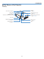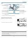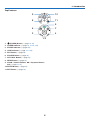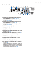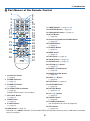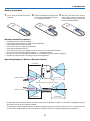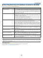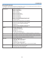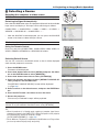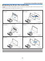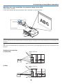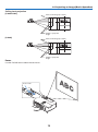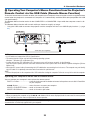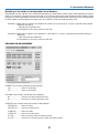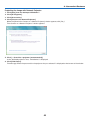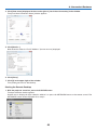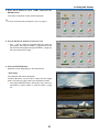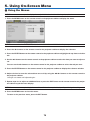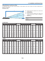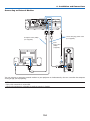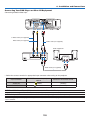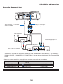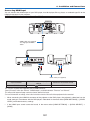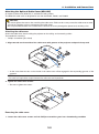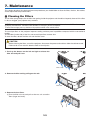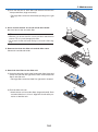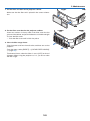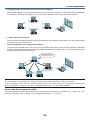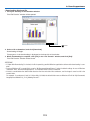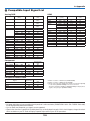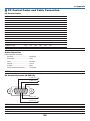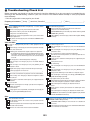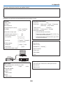
1
Portable Projector P420X/P350X/P350W User’s Manual Model No. NP-P420X, NP-P350X, NP-P350W 2nd edition, January 2011 • Macintosh, Mac OS X and PowerBook are trademarks of Apple Inc. registered in the U.S. and other countries. • Microsoft, Windows, Windows Vista, Internet Explorer, .NET Framework and PowerPoint are either a registered trademark or trademark of Microsoft Corporation in the United States and/or other countries. • MicroSaver is a registered trademark of Kensington Computer Products Group, a division of ACCO Brands. • Virtual Remote Tool uses WinI2C/DDC library, © Nicomsoft Ltd. • HDMI, the HDMI Logo and High-Definition Multimedia Interface are trademarks or registered trademarks of HDMI Licensing LLC. • Trademark PJLink is a trademark applied for trademark rights in Japan, the United States of America and other countries and areas. • Wi-Fi®, Wi-Fi Alliance®, and Wi-Fi Protected Access (WPA, WPA2)® are registered trademarks of the Wi-Fi Alliance. • Blu-ray is a trademark of Blu-ray Disc Association • Crestron, Crestron Control, and Crestron RoomView are trademarks or registered trademarks of Crestron Electronics, Inc. • Other product and company names mentioned in this user’s manual may be the trademarks or registered trademarks of their respective holders. • GPL/LGPL Software Licenses The product includes software licensed under GNU General Public License (GPL), GNU Lesser General Public License (LGPL), and others. For more information on each software, see “readme.pdf” inside the “about GPL&LGPL” folder on the supplied CDROM. NOTES (1)The contents of this user’s manual may not be reprinted in part or whole without permission. (2)The contents of this user’s manual are subject to change without notice. (3)Great care has been taken in the preparation of this user’s manual; however, should you notice any questionable points, errors or omissions, please contact us. (4)Notwithstanding article (3), NEC will not be responsible for any claims on loss of profit or other matters deemed to result from using the Projector. Important Information Safety Cautions Precautions Please read this manual carefully before using your NEC projector and keep the manual handy for future reference. CAUTION To turn off main power, be sure to remove the plug from power outlet. The power outlet socket should be installed as near to the equipment as possible, and should be easily accessible. CAUTION TO PREVENT SHOCK, DO NOT OPEN THE CABINET. THERE ARE HIGH-VOLTAGE COMPONENTS INSIDE. REFER SERVICING TO QUALIFIED SERVICE PERSONNEL. This symbol warns the user that uninsulated voltage within the unit may be sufficient to cause electrical shock. Therefore, it is dangerous to make any kind of contact with any part inside of the unit. This symbol alerts the user that important information concerning the operation and maintenance of this unit has been provided. The information should be read carefully to avoid problems. WARNING: TO PREVENT FIRE OR SHOCK, DO NOT EXPOSE THIS UNIT TO RAIN OR MOISTURE. DO NOT USE THIS UNIT’S PLUG WITH AN EXTENSION CORD OR IN AN OUTLET UNLESS ALL THE PRONGS CAN BE FULLY INSERTED. DOC Compliance Notice (for Canada only) This Class B digital apparatus meets all requirements of the Canadian Interference-Causing Equipment Regulations. Machine Noise Information Regulation - 3. GPSGV, The highest sound pressure level is less than 70 dB (A) in accordance with EN ISO 7779. CAUTION Avoid displaying stationary images for a prolonged period of time. Doing so can result in these images being temporarily sustained on the surface of the LCD panel. If this should happen, continue to use your projector. The static background from previous images will disappear. Disposing of your used product EU-wide legislation as implemented in each Member State requires that used electrical and electronic products carrying the mark (left) must be disposed of separately from normal household waste. This includes projectors and their electrical accessories or lamps. When you dispose of such products, please follow the guidance of your local authority and/or ask the shop where you purchased the product. After collecting the used products, they are reused and recycled in a proper way. This effort will help us reduce the wastes as well as the negative impact such as mercury contained in a lamp to the human health and the environment at the minimum level. The mark on the electrical and electronic products only applies to the current European Union Member States. i Important Information WARNING TO CALIFORNIA RESIDENTS: Handling the cables supplied with this product will expose you to lead, a chemical known to the State of California to cause birth defects or other reproductive harm. WASH HANDS AFTER HANDLING. RF Interference (for USA only) WARNING The Federal Communications Commission does not allow any modifications or changes to the unit EXCEPT those specified by NEC Display Solutions of America, Inc. in this manual. Failure to comply with this government regulation could void your right to operate this equipment. This equipment has been tested and found to comply with the limits for a Class B digital device, pursuant to Part 15 of the FCC Rules. These limits are designed to provide reasonable protection against harmful interference in a residential installation. This equipment generates, uses, and can radiate radio frequency energy and, if not installed and used in accordance with the instructions, may cause harmful interference to radio communications. However, there is no guarantee that interference will not occur in a particular installation. If this equipment does cause harmful interference to radio or television reception, which can be determined by turning the equipment off and on, the user is encouraged to try to correct the interference by one or more of the following measures: •Reorient or relocate the receiving antenna. •Increase the separation between the equipment and receiver. •Connect the equipment into an outlet on a circuit different from that to which the receiver is connected. •Consult the dealer or an experienced radio / TV technician for help. For UK only: In UK, a BS approved power cord with moulded plug has a Black (five Amps) fuse installed for use with this equipment. If a power cord is not supplied with this equipment please contact your supplier. Important Safeguards These safety instructions are to ensure the long life of your projector and to prevent fire and shock. Please read them carefully and heed all warnings. Installation • Do not place the projector in the following conditions: -on an unstable cart, stand, or table. -near water, baths, or damp rooms. -in direct sunlight, near heaters, or heat radiating appliances. -in a dusty, smoky or steamy environment. -on a sheet of paper or cloth, rugs or carpets. • If you wish to have the projector installed on the ceiling: -Do not attempt to install the projector yourself. -The projector must be installed by qualified technicians in order to ensure proper operation and reduce the risk of bodily injury. -In addition, the ceiling must be strong enough to support the projector and the installation must be in accordance with any local building codes. -Please consult your dealer for more information. ii Important Information WARNING •Do not use any other object than the projector’s sliding lens cover to cover the lens while the projector is on. Doing so can cause the object to get extremely hot, and possibly resulting in a fire or damage due to the heat emitted from the light output. Place the projector in a horizontal position The tilt angle of the projector should not exceed 10 degrees, nor should the projector be installed in any way other than the desktop and ceiling mount, otherwise lamp life could decrease dramatically. 10° Fire and Shock Precautions • Ensure that there is sufficient ventilation and that vents are unobstructed to prevent the build-up of heat inside your projector. Allow at least 4 inches (10cm) of space between your projector and a wall. • Do not try to touch the ventilation outlet on the left front (when seen from the front) as it can become heated while the projector is turned on and immediately after the projector is turned off. Parts of the projector may become temporarily heated if the projector is turned off with the POWER button or if the AC power supply is disconnected during normal projector operation. Use caution when picking up the projector. • Prevent foreign objects such as paper clips and bits of paper from falling into your projector. Do not attempt to retrieve any objects that might fall into your projector. Do not insert any metal objects such as a wire or screwdriver into your projector. If something should fall into your projector, disconnect it immediately and have the object removed by a qualified service personnel. • Do not place any objects on top of the projector. • Do not touch the power plug during a thunderstorm. Doing so can cause electrical shock or fire. • The projector is designed to operate on a power supply of 100-240V AC 50/60 Hz. Ensure that your power supply fits this requirement before attempting to use your projector. • Do not look into the lens while the projector is on. Serious damage to your eyes could result. • Keep any items (magnifying glass etc.) out of the light path of the projector. The light path being projected from the lens is extensive, therefore any kind of abnormal objects that can redirect light coming out of the lens, can cause an unpredictable outcome such as a fire or injury to the eyes. iii Important Information • Do not place any objects, which are easily affected by heat, in front of a projector exhaust vent. Doing so could lead to the object melting or getting your hands burned from the heat that is emitted from the exhaust. • Handle the power cord carefully. A damaged or frayed power cord can cause electric shock or fire. - Do not use any power cord other than the one supplied with the projector. - Do not bend or tug the power cord excessively. - Do not place the power cord under the projector, or any heavy object. - Do not cover the power cord with other soft materials such as rugs. - Do not heat the power cord. - Do not handle the power plug with wet hands. • Turn off the projector, unplug the power cord and have the projector serviced by a qualified service personnel under the following conditions: - When the power cord or plug is damaged or frayed. - If liquid has been spilled into the projector, or if it has been exposed to rain or water. - If the projector does not operate normally when you follow the instructions described in this user’s manual. - If the projector has been dropped or the cabinet has been damaged. - If the projector exhibits a distinct change in performance, indicating a need for service. • Disconnect the power cord and any other cables before carrying the projector. • Turn off the projector and unplug the power cord before cleaning the cabinet or replacing the lamp. • Turn off the projector and unplug the power cord if the projector is not to be used for an extended period of time. • When using a LAN cable (only models with the RJ-45 LAN port): For safety, do not connect to the connector for peripheral device wiring that might have excessive voltage. CAUTION • Do not use the tilt-foot for purposes other than originally intended. Misuses such as gripping the tilt-foot or hanging on the wall can cause damage to the projector. • Do not send the projector in the soft case by parcel delivery service or cargo shipment. The projector inside the soft case could be damaged. • Select [HIGH] in Fan mode if you continue to use the projector for consecutive days. (From the menu, select [SETUP] → [OPTIONS(1)] → [FAN MODE] → [HIGH].) • Do not try to touch the ventilation outlet on the left front (when seen from the front) as it can become heated while the projector is turned on and immediately after the projector is turned off. • Do not turn off the AC power for 60 seconds after the lamp is turned on and while the POWER indicator is blinking blue. Doing so could cause premature lamp failure. Remote Control Precautions • Handle the remote control carefully. • If the remote control gets wet, wipe it dry immediately. • Avoid excessive heat and humidity. • Do not short, heat, or take apart batteries. • Do not throw batteries into fire. • If you will not be using the remote control for a long time, remove the batteries. • Ensure that you have the batteries’ polarity (+/−) aligned correctly. • Do not use new and old batteries together, or use different types of batteries together. • Dispose of used batteries according to your local regulations. iv Important Information Note for US Residents The lamp in this product contains mercury. Please dispose according to Local, State or Federal Laws. Lamp Replacement • Use the specified lamp for safety and performance. • To replace the lamp, follow all instructions provided on page 147. • Be sure to replace the lamp and filter when the message [THE LAMP HAS REACHED THE END OF ITS USABLE LIFE. PLEASE REPLACE THE LAMP AND FILTER.] appears. If you continue to use the lamp after the lamp has reached the end of its usable life, the lamp bulb may shatter, and pieces of glass may be scattered in the lamp case. Do not touch them as the pieces of glass may cause injury. If this happens, contact your dealer for lamp replacement. A Lamp Characteristic The projector has a high-pressure mercury lamp as a light source. A lamp has a characteristic that its brightness gradually decreases with age. Also repeatedly turning the lamp on and off will increase the possibility of its lower brightness. CAUTION: • DO NOT TOUCH THE LAMP immediately after it has been used. It will be extremely hot. Turn the projector off and then disconnect the power cord. Allow at least one hour for the lamp to cool before handling. • When removing the lamp from a ceiling-mounted projector, make sure that no one is under the projector. Glass fragments could fall if the lamp has been burned out. About High Altitude mode • Set [FAN MODE] to [HIGH ALTITUDE] when using the projector at altitudes approximately 5500 feet/1600 meters or higher. Using the projector at altitudes approximately 5500 feet/1600 meters or higher without setting to [HIGH ALTITUDE] can cause the projector to overheat and the protector could shut down. If this happens, wait a couple minutes and turn on the projector. • Using the projector at altitudes less than approximately 5500 feet/1600 meters and setting to [HIGH ALTITUDE] can cause the lamp to overcool, causing the image to flicker. Switch [FAN MODE] to [AUTO]. • Using the projector at altitudes approximately 5500 feet/1600 meters or higher can shorten the life of optical components such as the lamp. About Copyright of original projected pictures: Please note that using this projector for the purpose of commercial gain or the attraction of public attention in a venue such as a coffee shop or hotel and employing compression or expansion of the screen image with the following functions may raise concern about the infringement of copyrights which are protected by copyright law. [ASPECT RATIO], [KEYSTONE], Magnifying feature and other similar features. Turkish RoHS information relevant for Turkish market EEE Yönetmeliğine Uygundur. This device is not intended for use in the direct field of view at visual display workplaces. To avoid incommoding reflections at visual display workplaces this device must not be placed in the direct field of view. v Important Information Information on Wireless LAN: In some areas and countries, the P420X, P350X, and P350W series projectors come standard with the USB Wireless LAN Unit. If you purchase the projector model without the Wireless LAN Unit, the optional Wireless LAN Unit must be installed to use the projector via a wireless connection. Note that use in other than supported countries and areas may violate radio wave laws of the country where a wireless LAN unit is used. Use the wireless LAN Unit according to the combinations of the product names and supported countries listed on page viii. Certificate marks and codes of the NP02LM Series (English) NP02LM1 Mexico CFT ID: RCPNENP10-0740 Brazil NP02LM2 Argentina CNC ID: C-8400 Australia New Zealand N56 Hong Kong HK0011000150 Vietnam FPT Distribution Co, Ltd. A0557-240610 A0557240610AE01A2 Indonesia 15809/POSTEL/2010 South Africa India 730/2010/WRLO Singapore Complies with IDA Standards DB00901 UAE TRA REGISTERED ER0042849/10 DEALER DA0038690/10 No: No: Pakistan South Korea 인증번호 : NDS-NP02LM vi Important Information English Hereby, NEC Display Solutions, Ltd. declares that this Wireless LAN Unit (Model: NP02LM) is in compliance with the essential requirements and other relevant provisions of Directive 1999/5/EC. Finnish NEC Display Solutions, Ltd. vakuuttaa täten että Wireless LAN Unit (Model: NP02LM) tyyppinen laite on direktiivin 1999/5/EY oleellisten vaatimusten ja sitä koskevien direktiivin muiden ehtojen mukainen. German Hiermit erklärt NEC Display Solutions, Ltd., dass sich dieser/diese/dieses Wireless LAN Unit (Model: NP02LM) in Übereinstimmung mit den grundlegenden Anforderungen und den anderen relevanten Vorschriften der Richtlinie 1999/5/EG befindet”. (BMWi) Hiermit erklärt NEC Display Solutions, Ltd. die Übereinstimmung des Gerätes Wireless LAN Unit (Model: NP02LM) mit den grundlegenden Anforderungen und den anderen relevanten Festlegungen der Richtlinie 1999/5/EG. (Wien) French Par la presente NEC Display Solutions, Ltd. declare que l’appareil Wireless LAN Unit (Model: NP02LM) est conforme aux exigences essentielles et aux autres dispositions pertinentes de la directive 1999/5/CE. Par la presente, NEC Display Solutions, Ltd. declare que ce Wireless LAN Unit (Model: NP02LM) est conforme aux exigences essentielles et aux autres dispositions de la directive 1999/5/CE qui lui sont applicables. Italian Con la presente NEC Display Solutions, Ltd. dichiara che questo Wireless LAN Unit (Model: NP02LM) è conforme ai requisiti essenziali ed alle altre disposizioni pertinenti stabilite dalla direttiva 1999/5/CE. Spanish Por medio de la presente NEC Display Solutions, Ltd. declara que el Wireless LAN Unit (Model: NP02LM) cumple con los requisitos esenciales y cualesquiera otras disposiciones aplicables o exigibles de la Directiva 1999/5/CE. Portuguese NEC Display Solutions, Ltd. declara que este Wireless LAN Unit (Model: NP02LM) está conforme com os requisitos essenciais e outras disposições da Directiva 1999/5/CE. Swedish Härmed intygar NEC Display Solutions, Ltd. att denna Wireless LAN Unit (Model: NP02LM) står I överensstämmelse med de väsentliga egenskapskrav och övriga relevanta bestämmelser som framgår av direktiv 1999/5/EG. Dutch Hierbij verklaart NEC Display Solutions, Ltd. dat het toestel Wireless LAN Unit (Model: NP02LM) in overeenstemming is met de essentiële eisen en de andere relevante bepalingen van richtlijn 1999/5/EG. Bij deze verklaart NEC Display Solutions, Ltd. dat deze Wireless LAN Unit (Model: NP02LM) voldoet aan de essentiële eisen en aan de overige relevante bepalingen van Richtlijn 1999/5/ EC. Danish Undertegnede NEC Display Solutions, Ltd. erklærer herved, at følgende udstyr Wireless LAN Unit (Model: NP02LM) overholder de væsentlige krav og øvrige relevante krav i direktiv 1999/5/EF. Greek ΜΕ ΤΗΝ ΠΑΡOΥΣΑ NEC Display Solutions, Ltd. ΔΗΛΩΝΕΙ OΤΙ Wireless LAN Unit (Model: NP02LM) ΣΥΜΜOΡΦΩΝΕΤΑΙ ΠΡOΣ ΤΙΣ OΥΣΙΩΔΕΙΣ ΑΠΑΙΤΗΣΕΙΣ ΚΑΙ ΤΙΣ ΛOΙΠΕΣ ΣXΕΤΙΚΕΣ ΔΙΑΤΑΞΕΙΣ ΤΗΣ OΔΗΓΙΑΣ 1999/5/ΕΚ. vii Important Information Table of Supported Areas and Countries Note that use with other than the combinations of the product names and supported countries and areas listed below may violate radio wave laws of the country where the device is used. Product Name Supported countries and areas NP02LM1 Brazil / Canada / Colombia / Mexico / Taiwan / United States NP02LM2 Argentina / Australia / Austria / Belgium / Bulgaria / Chile / China / Cyprus / Czech / Denmark / Ecuador / Egypt / Estonia / Finland / France / Germany / Greece / Hong Kong / Hungary / Iceland / India / Indonesia / Ireland / Israel / Italy / Japan / Latvia / Liechtenstein / Lithuania / Luxembourg / Malaysia / Malta / New Zealand / Norway / Oman / Pakistan / Peru / Philippines / Poland / Portugal / Romania / Saudi Arabia / Singapore / Slovak / Slovenia / South Africa / South Korea / Spain / Sri Lanka / Sweden / Switzerland / Thailand / The Netherlands / Turkey / Ukraine / United Arab Emirates / United Kingdom / Vietnam NP02LM3 Russia Cautions • Cautions on Usage Warning • The Wireless LAN Unit is not meant for use with facilities or equipment involving the safeguard of human life, such as medical equipment, nuclear facilities or equipment, aeronautical or space equipment, transportation facilities or equipment, etc., or with facilities or equipment requiring high levels of reliability. Do not use the Wireless LAN Unit in such cases. • Do not use the Wireless LAN Unit near cardiac pacemakers. • Do not use the Wireless LAN Unit near medical equipment. Doing so may cause electromagnetic interference with the medical equipment, possible leading to death. • Do not disassemble or modify the Wireless LAN Unit in any way. Doing so could lead to fire or electric shock. • Do not use the Wireless LAN Unit in wet or moist places, such as in bathrooms or near humidifiers. Doing so could lead to fire, electric shock or malfunction. Caution To prevent damage due to static electricity, eliminate any static electricity from your body before touching the Wireless LAN Unit. • Static electricity from the human body may damage the Wireless LAN Unit. Before touching the Wireless LAN Unit, touch an aluminum sash, a door knob, or some other metal object around you to eliminate the static electricity. Caution The radio waves used by the Wireless LAN Unit pass through the wood or glass used in normal homes (but not through window panes with built-in metallic mesh). The radio waves do not pass through iron reinforcing bars, metal or concrete, however, so the Wireless LAN Unit cannot be used for communicating through walls or floors made with these materials. viii Important Information • FCC Compliance This device complies with Part 15 of the FCC Rules. Operation is subject to the following two conditions:(1) this device may not cause harmful interference and (2) this device must accept any interference received, including interference that may cause undesired operation. This equipment has been tested and found to comply with the limits for a Class B Personal Computer and Peripheral, pursuant to Part 15 of the FCC Rules. These limits are designed to provide reasonable protection against harmful interference in a residential installation. This equipment generates, uses and can radiate radio frequency energy and, if not installed and used in accordance with the instructions, may cause harmful interference to radio communications. However, there is no guarantee that interference will not occur in a particular installation. If this equipment does cause harmful interference to radio or television reception, which can be determined by turning the equipment off and on, the user is encouraged to try to correct the interference by one or more of the following measures: • Reorient or relocate the receiving antenna. • Increase the separation between the equipment and receiver. • Connect the equipment into an outlet on a circuit different from that to which the receiver is connected. • Consult the dealer or an experienced radio/TV technician for help. This equipment has been tested to comply with the limits for a Class B personal computer and periph-eral, pursuant to Subpart B of Part 15 of FCC Rules. Only peripherals (computer input/output devices, terminals, printers, etc.) certified (DoC) or verified to comply with Class B limits may be attached to this equipment. Operation with non-certified (DoC) or non-verified personal computer and/or peripherals is likely to result in Interference to radio and TV reception. The connection of a unshielded equipment interface cable to this equipment will invalidate the FCC Certification of this device and may cause interference levels which Exceed the limits established by FCC for equipment. You are cautioned that changes or modifications not expressly approved by the party responsible for compliance could void your authority to operate the equipment. Regulatory Information/Disclaimers Installation and use of this Wireless LAN device must be in strict accordance with the instructions included in the user documentation provided with the product. Any changes or modifications (including the antennas) made to this device that are not expressly approved by the manufacturer may void the user’s authority to operate the equipment. The manufacturer is not responsible for any radio or television interference caused by unauthorized modification of this device, or the substitution of the connecting cables and equipment other than manufacturer specified. It is the responsibility of the user to correct any interference caused by such unauthorized modification, substitution or attachment. Manufacturer and its authorized resellers or distributors will assume no liability for any damage or violation of government regulations arising from failing to comply with these guidelines. IEEE 802.11b or 802.11g operation of this product in the U.S.A. is firmware-limited to channels 1 through 11. CAUTION This equipment complies with FCC RF radiation exposure limits set forth for an uncontrolled environment. This device and its antenna must not be co-located or operating in conjunction with any other antenna or transmitter. To comply with FCC RF exposure compliance requirements, the antenna used for this transmitter must be installed to provide a separation distance of at least 7.87"/20cm from all persons and must not be co-located or operating in conjunction with any other antenna or transmitter. This Class B digital apparatus complies with Canadian RSS-210. Cet appareil numerique de la Classe B est conforme a la norme CNR-210 du Canada. Industry Canada Statement This device complies with RSS-210 of the Industry Canada Rules. Operation is subject to the following two conditions: 1) this device may not cause interference and 2) this device must accept any interference, including interference that may cause undesired operation of the device ix Important Information Regulatory Statement: Operation of this device is subjected to the following National regulations and may be prohibited to use if certain restriction should be applied. France: Outdoor use limited to 10mW e.i.r.p. within the band 2454 – 2483.5 MHz. Derogation in French overseas departments of Guyane and La Reunion: outdoor use not allowed in band 2400 - 2420 MHz. • Cautions on security when using wireless LAN products With a wireless LAN, radio waves are used instead of LAN cables for the exchange of data between the wireless access points (computers, etc.), offering the advantage that LAN connections can be made freely within the range of the radio waves. On the other hand, the radio waves reach all points within this range, regardless of walls or other obstacles, possibly resulting in the problems described below if the proper security measures are not taken. • Contents of transmissions may be intercepted Malicious third parties may purposely intercept the radio waves and steal information contained in the transmissions, including such personal information as ID numbers, passwords, credit card numbers, e-mail messages, etc. • Improper intrusions Malicious third parties may without permission access the personal or company network and steal personal or confidential information, pretend to be someone else and leak incorrect information, rewrite information that has been intercepted, introduce computer viruses or otherwise damage data or the system, etc. Wireless LAN cards and wireless access points generally include security measures for dealing with these problems. Making the proper security settings before using the products can reduce the risk of such problems arising. We recommend that you fully understand the problems that can arise when using the products without making the security settings, then that you make the security settings based on your own decision and at your own discretion. x Important Information Specifications (1) Specifications common to the NP02LM series Operating Voltage 5V (power supplied from the projector) MAX Amps 460 mA Wireless Standard IEEE802.11b / IEEE802.11g / IEEE802.11n Modulation Method CCK / DQPSK / DBPSK / OFDM / DS-SS LED Display (Green) During communication: blinking Standby: slow blinking No operation: light off Interface USB 2.0 (connected to USB wireless LAN port on the projector) Dimensions Width: 1.1" / 28 mm Height: 0.43" / 11 mm Length: 3.03" / 81 mm (including the cap) Weight 0.049 lbs / 22 g (including the cap) Environmental Considerations Operational Temperatures : 41° to 104°F / 5° to 40°C, 20% to 80% humidity (non-condensing) Storage Temperatures : 14° to 122°F (-10° to 50°C), 20% to 80% humidity (non-condensing) (2) Compliant standards according to model NP02LM1 IEEE802.11b IEEE802.11g IEEE802.11n Center Frequency Range/ Operating channels 2412 to 2462 MHz 1 to 11 channels Transmission method DS-SS method (direct dispersion spectrum dispersion method) Data Rates 11/5.5/2/1 Mbps Center Frequency Range/ Operating channels 2412 to 2462 MHz 1 to 11 channels Transmission method OFDM method (Orthogonal Frequency Division Multiplexing method) Data Rates 54/48/36/24/18/12/9/6 Mbps Center Frequency Range/ Operating channels 2412 to 2462 MHz 1 to 11 channels Transmission method OFDM method (Orthogonal Frequency Division Multiplexing method)/ MIMO method (Multiple-Input Multiple-Output method) Data Rates* When dual channel communication is disabled 130/117/104/78/52/39/26/19.5/13 Mbps When dual channel communication is enabled 300/270/243/216/162/108/81/54/40.5/27/13.5 Mbps xi Important Information NP02LM2 IEEE802.11b IEEE802.11g IEEE802.11n Center Frequency Range/ Operating channels 2412 to 2472 MHz 1 to 13 channels Transmission method DS-SS method (direct dispersion spectrum dispersion method) Data Rates 11/5.5/2/1 Mbps Center Frequency Range/ Operating channels 2412 to 2472 MHz 1 to 13 channels Transmission method OFDM method (Orthogonal Frequency Division Multiplexing method) Data Rates 54/48/36/24/18/12/9/6 Mbps Center Frequency Range/ Operating channels 2412 to 2472 MHz 1 to 13 channels Transmission method OFDM method (Orthogonal Frequency Division Multiplexing method)/ MIMO method (Multiple-Input Multiple-Output method) Data Rates* When dual channel communication is disabled 130/117/104/78/52/39/26/19.5/13 Mbps When dual channel communication is enabled 300/270/243/216/162/108/81/54/40.5/27/13.5 Mbps Center Frequency Range/ Operating channels 2412 to 2472 MHz 1 to 13 channels Transmission method DS-SS method (direct dispersion spectrum dispersion method) Data Rates 11/5.5/2/1 Mbps Center Frequency Range/ Operating channels 2412 to 2472 MHz 1 to 13 channels Transmission method OFDM method (Orthogonal Frequency Division Multiplexing method) Data Rates 54/48/36/24/18/12/9/6 Mbps Center Frequency Range/ Operating channels Not available Transmission method Not available Data Rates Not available NP02LM3 IEEE802.11b IEEE802.11g IEEE802.11n * Dual channel communication will be automatically switched between "enabled" and "disabled" according to the usage environment. 注意 依據 低功率電波輻射性電機管理辦法 第十二條 經型式認證合格之低功率射頻電機,非經許可,公司、商號或使用者均不得擅自變更頻率、加大功率或 變更原設計之特性及功能。 第十四條 低功率射頻電機之使用不得影響飛航安全及干擾合法通信;經發現有干擾現象時,應立即停用,並改善 至無干擾時方得繼續使用。前項合法通信,指依電信規定作業之無線電信。低功率射頻電機須忍受合法通信或工 業、科學及醫療用電波輻射性電機設備之干擾。 xii Table of Contents Important Information. ...........................................................................................i 1. Introduction........................................................................................................... 1 1 What’s in the Box?.......................................................................................................... 1 Introduction to the Projector........................................................................................... 2 Congratulations on Your Purchase of the Projector.................................................. 2 Features you’ll enjoy:................................................................................................ 2 About this user’s manual........................................................................................... 3 Part Names of the Projector........................................................................................... 4 Front/Top................................................................................................................... 4 Rear.......................................................................................................................... 5 Top Features............................................................................................................. 6 Terminal Panel Features........................................................................................... 7 Part Names of the Remote Control................................................................................ 8 Battery Installation.................................................................................................... 9 Remote Control Precautions..................................................................................... 9 Operating Range for Wireless Remote Control......................................................... 9 Operating Environment for Software Included on CD-ROM......................................... 10 Operating Environment........................................................................................... 11 2. Projecting an Image (Basic Operation)............................................... 12 Flow of Projecting an Image......................................................................................... 12 Connecting Your Computer/Connecting the Power Cord.............................................. 13 Turning on the Projector............................................................................................... 14 Note on Startup screen (Menu Language Select screen)....................................... 15 Selecting a Source....................................................................................................... 16 Selecting the computer or video source................................................................. 16 Adjusting the Picture Size and Position........................................................................ 17 Adjusting the vertical position of a projected image (Lens shift)............................. 18 Focus...................................................................................................................... 19 Zoom....................................................................................................................... 20 Adjust the Tilt Foot.................................................................................................. 21 Correcting Keystone Distortion Manually..................................................................... 22 Adjusting with buttons on the cabinet..................................................................... 22 Adjusting with the remote control............................................................................ 23 Optimizing Computer Signal Automatically.................................................................. 24 Adjusting the Image Using Auto Adjust................................................................... 24 Turning Up or Down Volume......................................................................................... 24 Turning off the Projector............................................................................................... 25 After Use...................................................................................................................... 26 3. Convenient Features. .................................................................................... 27 1 Turning off the Image and Sound................................................................................. 27 2 Freezing a Picture........................................................................................................ 27 Enlarging a Picture....................................................................................................... 27 Changing Eco Mode/Checking Energy-Saving Effect Using Eco Mode [ECO MODE].................................................................................................................... 28 xiii Table of Contents Checking Energy-Saving Effect [CARBON METER].............................................. 29 5 Preventing the Unauthorized Use of the Projector [SECURITY].................................. 30 Operating Your Computer’s Mouse Functions from the Projector’s Remote Control via the USB Cable (Remote Mouse Function)........................................................ 33 Projecting Your Computer’s Screen Image from the Projector via the USB Cable (USB Display)......................................................................................................... 34 Controlling the Projector by Using an HTTP Browser.................................................. 36 Projecting Your Computer’s Screen Image from the Projector via a Network [NETWORK PROJECTOR]..................................................................................... 43 Using the Projector to Operate Your Computer via a Network [REMOTE DESKTOP].............................................................................................................. 47 4. Using the Viewer.............................................................................................. 52 ❶ What you can do with the Viewer.................................................................................. 52 ❷ Preparing presentation materials................................................................................. 55 ❸ Projecting images stored in a USB memory device..................................................... 56 Starting the Viewer.................................................................................................. 56 Exiting the Viewer................................................................................................... 59 Names and functions of Viewer screen................................................................... 60 Viewer option settings............................................................................................. 65 ❹ Projecting data from shared folder............................................................................... 68 Connecting the projector to the shared folder . ...................................................... 68 Disconnecting the shared folder from the projector................................................ 71 ❺ Projecting data from media server............................................................................... 72 Setting up “Media Sharing” in Windows Media Player 11....................................... 72 Setting up “Media Sharing” in Windows Media Player 12....................................... 74 Connecting the projector to the media server......................................................... 75 Disconnecting the projector from the media server................................................ 76 ❻ Restrictions on displaying files..................................................................................... 77 Some restrictions on PowerPoint files..................................................................... 77 Some restrictions on PDF files............................................................................... 77 5. Using On-Screen Menu. ............................................................................... 78 Using the Menus........................................................................................................... 78 2 Menu Elements............................................................................................................. 79 3 List of Menu Items........................................................................................................ 80 4 Menu Descriptions & Functions [SOURCE]................................................................. 82 COMPUTER 1 and 2.............................................................................................. 82 HDMI....................................................................................................................... 82 VIDEO..................................................................................................................... 82 S-VIDEO................................................................................................................. 82 VIEWER.................................................................................................................. 82 NETWORK.............................................................................................................. 82 USB DISPLAY......................................................................................................... 82 5 Menu Descriptions & Functions [ADJUST]................................................................... 83 [PICTURE].............................................................................................................. 83 [IMAGE OPTIONS]................................................................................................. 86 [AUDIO]................................................................................................................... 90 xiv Table of Contents 6 Menu Descriptions & Functions [SETUP]..................................................................... 91 [GENERAL]............................................................................................................. 91 [MENU]................................................................................................................... 93 [INSTALLATION]..................................................................................................... 95 [OPTIONS(1)]......................................................................................................... 97 [OPTIONS(2)]......................................................................................................... 99 7 Menu Descriptions & Functions [INFO.]..................................................................... 101 [USAGE TIME]...................................................................................................... 101 [SOURCE]............................................................................................................ 102 [WIRED LAN]........................................................................................................ 102 [WIRELESS LAN]................................................................................................. 102 [VERSION(1)]....................................................................................................... 103 [VERSION(2)]....................................................................................................... 103 [OTHERS]............................................................................................................. 103 8 Menu Descriptions & Functions [RESET]................................................................... 104 Returning to Factory Default [RESET].................................................................. 104 ❾ Application Menu........................................................................................................ 105 IMAGE EXPRESS UTILITY.................................................................................. 105 DESKTOP CONTROL UTILITY............................................................................ 105 NETWORK PROJECTOR..................................................................................... 106 REMOTE DESKTOP CONNECTION................................................................... 106 NETWORK SETTINGS......................................................................................... 107 TOOLS.................................................................................................................. 123 6. Installation and Connections.................................................................. 128 Setting Up the Screen and the Projector.................................................................... 128 Selecting a Location............................................................................................. 128 Throw Distance and Screen Size.......................................................................... 130 Making Connections................................................................................................... 132 Connecting Your Computer................................................................................... 132 Connecting an External Monitor........................................................................... 134 Connecting Your DVD Player or Other AV Equipment........................................... 135 Connecting Component Input............................................................................... 136 Connecting HDMI Input........................................................................................ 137 Connecting to a Wired LAN.................................................................................. 138 Connecting to a Wireless LAN (NP02LM series).................................................. 139 Attaching the Optional Cable Cover (NP01CV).................................................... 142 7. Maintenance..................................................................................................... 143 Cleaning the Filters.................................................................................................... 143 2 Cleaning the Lens...................................................................................................... 146 3 Cleaning the Cabinet.................................................................................................. 146 4 Replacing the Lamp and the Filters............................................................................ 147 8. User Supportware. ........................................................................................ 152 Installing Software Program....................................................................................... 152 Installation for Windows software.......................................................................... 152 Installation for Macintosh software........................................................................ 154 Using the Computer Cable (VGA) to Operate the Projector (Virtual Remote Tool).... 155 xv Table of Contents Projecting Your Computer’s Screen Image from the Projector over a LAN (Image Express Utility Lite)............................................................................................... 160 Projecting an Image from an Angle (Geometric Correction Tool in Image Express Utility Lite)............................................................................................................. 163 What you can do with GCT................................................................................... 163 Projecting an Image from an Angle (GCT)............................................................ 163 Projecting Images or Videos from the Projector over a LAN (Image Express Utility 2.0)........................................................................................................................ 165 What you can do with Image Express Utility 2.0................................................... 165 Connecting the projector to a LAN........................................................................ 166 Basic Operation of Image Express Utility 2.0........................................................ 167 Using the Projector to Operate Your Computer over a LAN (Desktop Control Utility 1.0)........................................................................................................................ 176 What you can do with Desktop Control Utility 1.0................................................. 176 Connecting the projector to a LAN........................................................................ 176 Using the projector to operate your computer’s desktop screen........................... 177 Controlling the Projector over a LAN (PC Control Utility Pro 4).................................. 185 Converting PowerPoint files to Slides (Viewer PPT Converter 3.0)............................ 186 Projecting Your Mac’s Screen Image from the Projector over a LAN (Image Express Utility 2 for Mac)...................................................................................... 188 What you can do with Image Express Utility 2...................................................... 188 Operating environment......................................................................................... 188 Connecting the projector to a LAN........................................................................ 188 Using Image Express Utility 2............................................................................... 189 9. Appendix............................................................................................................. 192 Troubleshooting.......................................................................................................... 192 Indicator Messages............................................................................................... 192 Common Problems & Solutions............................................................................ 193 If there is no picture, or the picture is not displayed correctly................................ 194 Specifications............................................................................................................. 195 Cabinet Dimensions................................................................................................... 197 4 Pin Assignments of D-Sub COMPUTER Input Connector......................................... 198 5 Compatible Input Signal List....................................................................................... 199 6 PC Control Codes and Cable Connection.................................................................. 200 7 Troubleshooting Check List......................................................................................... 201 8 TravelCare Guide........................................................................................................ 203 xvi 1. Introduction 1 What’s in the Box? Make sure your box contains everything listed. If any pieces are missing, contact your dealer. Please save the original box and packing materials if you ever need to ship your projector. Projector Remote control (7N900922) Batteries (AAA × 2) Computer cable (VGA) (7N520073) Power cord (US: 7N080236) (EU: 7N080022) For North America only Registration card Limited warranty • Important Infomation (For North America: 7N8N1261) (For Other countries than North America: 7N8N1261 and 7N8N1271) • Quick Setup Guide (For North America: 7N8N1281) (For Other countries than North America: 7N8N1281 and 7N8N1291) NEC Projector CD-ROM User’s manual (PDF) and the utility software (7N951551) For customers in Europe: You will find our current valid Guarantee Policy on our Web Site: www.nec-display-solutions.com In some areas and countries, the projector comes standard with the USB Wireless LAN Unit. If you purchase the projector model without the Wireless LAN Unit, the optional Wireless LAN Unit must be installed to use the projector via a wireless connection. Unless otherwise described in the user’s manual, the drawings for the projector cabinet show examples of the P420X. 1 1. Introduction Introduction to the Projector This section introduces you to your new projector and describes the features and controls. Congratulations on Your Purchase of the Projector This projector is one of the very best projectors available today. The projector enables you to project precise images up to 300 inches across (measured diagonally) from your PC or Macintosh computer (desktop or notebook), VCR, DVD player, or document camera. You can use the projector on a tabletop or cart, you can use the projector to project images from behind the screen, and the projector can be permanently mounted on a ceiling*1. The remote control can be used wirelessly. *1 Do not attempt to mount the projector on a ceiling yourself. The projector must be installed by qualified technicians in order to ensure proper operation and reduce the risk of bodily injury. In addition, the ceiling must be strong enough to support the projector and the installation must be in accordance with any local building codes. Please consult your dealer for more information. Features you’ll enjoy: • Quick start (3 seconds*1), Quick Power Off (0 seconds), Direct Power Off 3 seconds*1 after turning on the power, the projector is ready to display PC or video images. The projector can be put away immediately after the projector is powered down. No cool down period is required after the projector is turned off from the remote control or cabinet control panel. The projector has a feature called “Direct Power Off”. This feature allows the projector to be turned off (even when projecting an image) by using the Main Power Switch or disconnecting the AC power supply. To turn off the AC power supply when the projector is powered on, use a power strip equipped with a switch and a breaker. *1 The quick start time is only when [STANDBY MODE] is set to [NORMAL] in the on-screen message. • 0.2 W (100-130 V AC)/0.4 W (200-240 V AC) in standby condition with energy saving technology Selecting [POWER-SAVING] for [STANDBY MODE] from the menu can put the projector in power-saving mode that consumes only 0.2 W (100-130 V AC)/0.4 W (200-240 V AC). • Carbon Meter This feature will show energy-saving effect in terms of CO2 emission reduction (kg) when the projector’s [ECO MODE] is set to [AUTO ECO], [ECO1], or [ECO2]*2. The amount of CO2 emission reduction will be displayed in the confirmation message at the time of power-off and in the INFO of the on-screen menu. *2 [ECO2] is available on P350X only. • Lamp life up to 5000 hours (P350X)/3500 hours (P420X/P350W) without cleaning the filters regularly Using in Eco Mode allows you to prolong the projector’s lamp life up to 5000 hours (up to 4000 hours in NORMAL Mode (ECO Mode OFF)). For P420X and P350W: Using in Eco Mode allows you to prolong the projector’s lamp life up to 3500 hours (up to 3000 hours in NORMAL Mode (ECO Mode OFF)) The two-layer, large filters require no regular cleaning. Filter replacement is requred only when lamp replacement is done. • Vertical lens shift mechanism offers installation flexibility Manual lens shift that can be adjusted by turning dials on the top of the projector. • HDMI input port provides digital signal The HDMI input provides HDCP compatible digital signals. The HDMI input also supports audio signal. 2 1. Introduction • 10 W built-in speaker for an integrated audio solution Powerful 10 watt monaural speaker provides volume need for large rooms. • The supplied remote control allows you to assign a CONTROL ID to the projector Multiple projectors can be operated separately and independently with the same single remote control by assigning an ID number to each projector. • Vertical keystone correction Keystone feature allows the projector to correct vertical distortion. • USB Display Using a commercially available USB cable (compatible with USB 2.0 specifications) to connect the computer with the projector allows you to send your computer screen image to the projector without the need of a traditional computer cable (VGA). • Integrated RJ-45 connector for wired networking capability along with wireless networking capabilities An RJ-45 connector is standard. A wireless LAN unit is equipped with the projector for models distributed in North America models. An optional wireless LAN unit is available for models for Europe, Australia, Asia and other countries than North America. • Software programs (User Supportware) contained in the supplied CD-ROM The supplied NEC Projector includes seven programs: Virtual Remote Tool, Image Express Utility Lite, Image Express Utility 2.0, Desktop Control Utility 1.0, PC Control Utility Pro 4, Viewer PPT Converter 3.0, and Image Express Utility 2 for Mac. • LAN-compatible Viewer The projector’s built-in Viewer allows you to view images or movie files in the shared folder of your PC connected to a wired or wireless LAN. * The Viewer supports the Media Sharing function of Windows Media Player 11. • AUTO POWER ON and AUTO POWER OFF features The AUTO POWER ON(AC), AUTO POWER ON(COMP1), AUTO POWER OFF, and OFF TIMER features eliminate the need to always use the POWER button on the remote control or projector cabinet. • Preventing unauthorized use of the projector Enhanced smart security settings for keyword protection, cabinet control panel lock, security slot, and security chain opening to help prevent unauthorized access, adjustments and theft deterrence. • High resolution up to UXGA High resolution display - up to UXGA compatible, XGA (P420X/P350X)/WXGA (P350W) native resolution. • Crestron RoomView® supported The projector suppors Crestron RoomView which allows you to control and manage equipment connected to your network from your computer. About this user’s manual The fastest way to get started is to take your time and do everything right the first time. Take a few minutes now to review the user’s manual. This may save you time later on. At the beginning of each section of the manual you’ll find an overview. If the section doesn’t apply, you can skip it. 3 1. Introduction Part Names of the Projector Front/Top Controls (→ page 6) Zoom Lever (→ page 20) Focus Lever (→ page 19) Lens Shift Dial (Vertical) (→ page 18) Ventilation (outlet) Heated air is exhausted from here. Ventilation (inlet) / Filter Cover (→ page 143, 150) Lens Cover Adjustable Tilt Foot Lever (→ page 21) Remote Sensor (→ page 9) Adjustable Tilt Foot (→ page 21) Lens 4 1. Introduction Rear Port Cover for USB Wireless LAN Unit When using the USB Wireless LAN Unit, first remove the cover. (→ page 141) Remote Sensor (→ page 9) Lamp Cover (→ page 148) Built-in Security Slot ( Monaural Speaker (10 W) )* Terminal Panel (→ page 7) AC Input Connect the supplied power cord’s three-pin plug here, and plug the other end into an active wall outlet. (→ page 13) Security chain opening Attach an anti-theft device. The security chain opening accepts security wires or chains up to 0.18 inch/4.6 mm in diameter. Cable cover connection (right and left) Screw holes and grooves for the optional cable cover Rear Foot (→ page 21) * This security slot supports the MicroSaver ® Security System. Opening and closing the lens cover Slide the lens cover to the left to uncover the lens. To cover the lens, slide the lens cover to the right. NOTE: • The lens cover works in conjunction with the AV mute function. Closing the lens cover will turn off the image and sound during normal projector operation; opening it will restore the image and sound. With the lens cover closed the image and sound is turned off, however the lamp is still lit. If the projector stays this way for about 2 hours, it will turn off automatically. • Do not pull the lens cover with excessive force or apply strong pressure in either the up or down direction. Doing so can cause damage to the lens cover sliding mechanism! 5 1. Introduction Top Features 9 10 8 11 5 6 7 3 4 1/2 1. (POWER) Button (→ page 14, 25) 2. POWER Indicator (→ page 13, 14, 25, 192) 3. STATUS Indicator (→ page 192) 4. LAMP Indicator (→ page 147, 192) 5. ECO Button (→ page 28) 6. SOURCE Button (→ page 16) 7. AUTO ADJ. Button (→ page 24) 8. MENU Button (→ page 78) 9. / Volume Buttons / Keystone Buttons (→ page 22, 24) 10.ENTER Button (→ page 78) 11.EXIT Button (→ page 78) 6 1. Introduction Terminal Panel Features 13 12 6 5 4 10 1. COMPUTER 1 IN/ Component Input Connector (Mini D-Sub 15 Pin) (→ page 132, 136, 157) 2. COMPUTER 1 AUDIO IN Mini Jack (Stereo Mini) (→ page 132, 134, 136) 3. COMPUTER 2 IN / Component Input Connector (Mini D-Sub 15 Pin) (→ page 132, 136) 4. COMPUTER 2 AUDIO IN Mini Jack (Stereo Mini) (→ page 132, 134, 136) 5. HDMI IN Connector (Type A) (→ page 132, 137) 6. USB (PC) Port (Type B) (→ page 33, 34, 132) 7. MONITOR OUT (COMP. 1) Connector (Mini D-Sub 15 Pin) (→ page 134) 8. AUDIO OUT Mini Jack (Stereo Mini) (→ page 134) 9. S-VIDEO IN Connector (Mini DIN 4 Pin) (→ page 135) 10.VIDEO IN Connector (RCA) (→ page 135) 11.VIDEO/S-VIDEO AUDIO IN L/MONO, R (RCA) (→ page 135) 12.LAN Port (RJ-45) (→ page 141) 13.USB Port (Type A) (→ page 59, 180) 14.PC CONTROL [PC CONTROL] Port (D-Sub 9 Pin) (→ page 200) Use this port to connect a PC or control system. This enables you to control the projector using serial communication protocol. If you are writing your own program, typical PC control codes are on page 200. 7 3 2 1 11 9 7 8 14 1. Introduction Part Names of the Remote Control 1 2 4 8 9 11 14 17 18 21 22 23 26 32 3 7 5 6 10 15 13 12 16 19 20 25 27 24 28 29 11.VIEWER Button (→ page 16, 56) 12.NETWORK Button (→ page 16) 13.USB DISPLAY Button (→ page 16) 14.ID SET Button (→ page 96) 15.Numeric Keypad Button/CLEAR Button (→ page 96) 16.FREEZE Button (→ page 27) 17.AV-MUTE Button (→ page 27) 18.MENU Button (→ page 78) 19.EXIT Button (→ page 78) 30 31 20. Button (→ page 78) 21.ENTER Button (→ page 78) 22.D-ZOOM (+)(–) Button (→ page 27) 23.MOUSE L-CLICK Button* (→ page 33) 24.MOUSE R-CLICK Button* (→ page 33) 1. Infrared Transmitter (→ page 9) 25.PAGE / Button* (→ page 33) 2. POWER ON Button (→ page 14) 26.ECO Button (→ page 28) 3. POWER OFF Button (→ page 25) 27.KEYSTONE Button (→ page 23) 4, 5, 6. COMPUTER 1/2/3 Button (→ page 16) (COMPUTER 3 button is not available.) 28.PICTURE Button (→ page 83, 85) 29.VOL. (+)(–) Button (→ page 24) 7. AUTO ADJ. Button (→ page 24) 30.ASPECT Button (→ page 88) 8. VIDEO Button (→ page 16) 31.FOCUS/ZOOM Button (not available on this series of projectors) 9. S-VIDEO Button (→ page 16) 32.HELP Button (→ page 101) 10.HDMI Button (→ page 16) * The PAGE /, , MOUSE L-CLICK and MOUSE R-CLICK buttons work only when a USB cable is connected with your computer.. 8 1. Introduction Battery Installation 1 Press firmly and slide the battery cover off. 2 Install new batteries (AAA). Ensure that you have the batteries’ polarity (+/−) aligned correctly. 3 Slip the cover back over the batteries until it snaps into place. Do not mix different types of batteries or new and old batteries. EN OP EN OP Remote Control Precautions • • • • • • • • • Handle the remote control carefully. If the remote control gets wet, wipe it dry immediately. Avoid excessive heat and humidity. Do not short, heat, or take apart batteries. Do not throw batteries into fire. If you will not be using the remote control for a long time, remove the batteries. Ensure that you have the batteries’ polarity (+/−) aligned correctly. Do not use new and old batteries together, or use different types of batteries together. Dispose of used batteries according to your local regulations. Operating Range for Wireless Remote Control 7 m/22 feet 30° 30° 30° Remote control 7 m/22 feet 30° Remote sensor on projector cabinet 30° Remote control 30° 30° 30° 7 m/22 feet 7 m/22 feet • The infrared signal operates by line-of-sight up to a distance of about 22 feet/7 m and within a 60-degree angle of the remote sensor on the projector cabinet. • The projector will not respond if there are objects between the remote control and the sensor, or if strong light falls on the sensor. Weak batteries will also prevent the remote control from properly operating the projector. 9 1. Introduction Operating Environment for Software Included on CD-ROM Names and Features of Bundled Software Programs Name of software program Virtual Remote Tool Features This is a software program used to control the power ON/OFF and source selection of the projector from your computer by using the supplied computer cable (VGA) and it is also used to send an image to the projector and register it as the logo data of the projector. After registering it, you can lock the logo to prevent it from changing. (→ page 155) Image Express Utility Lite • This is a software program used to project your computer’s screen over the USB cable or the wired/wireless network. The computer cable (VGA) is not required. (→ page 34, page 160) • This software program can be used to control the power ON/OFF and source selection of the projector from your computer. • The Geometric Correction Tool (GCT) function allows you to correct distortion of images projected on a curved wall. (→ page 163) Image Express Utility 2.0 • This is a software program used to send the screens of your personal computers to the projector via wired/wireless LAN (Meeting mode). Projected images can be transferred and saved to personal computers. When “Meeting Mode” is used, projected images can be sent and saved to the personal computers. Images can be sent from a personal computer to not only one projector but also to two or more projectors at the same time. (→ page 165) Desktop Control Utility 1.0 • This is a software program used to operate the desktop screen of a personal computer at a remote location by using a projector via wired/wireless LAN. (→ page 176) PC Control Utility Pro 4 This is a software program used to operate the projector from the computer when the computer and the projector are connected with LAN (wired or wireless) or a serial cable. (→ page 185) Viewer PPT Converter 3.0 This is a software program used to convert files created with PowerPoint into JPEG files that can be displayed with the viewer function of the projector when a USB memory device is inserted into the projector. (→ page 186) Image Express Utility for Mac • This is a software program used to send the Mac’s screen image to the projector over a network (wired or wireless LAN). (→ page 188) For Mac’s operating environment, see page 188. NOTE: • Image Express Utility Lite does not support “Meeting Mode” in Image Express Utility 2.0 and Image Express Utility 2 for Mac included with our other models. Download service For the update information about these software programs, visit our website: URL: http://www.nec-display.com/dl/en/index.html 10 1. Introduction Operating Environment The following is the operating environment for Image Express Utility Lite. For the operating environment of other software program, refer to the help function of each software program. Supported OS Windows 7 Home Basic Windows 7 Home Premium Windows 7 Professional Windows 7 Ultimate Windows 7 Enterprise Windows Vista Home Basic Windows Vista Home Premium Windows Vista Business Windows Vista Ultimate Windows Vista Enterprise Windows XP Home Edition Service Pack 3 or later Windows XP Professional Service Pack 3 or later • Only 32-bit version • Windows power-saving function is not supported. Processor • Windows 7/Windows Vista Pentium M 1.2 GHz equivalent or higher required Dual core 1.5 GHz or higher recommended • Windows XP Pentium M 1.0 GHz equivalent or higher required Dual core 1.0 GHz or higher recommended Memory • Windows 7/Windows Vista 512 MB or more required 1 GB or more recommended • Windows XP 256 MB or more required 512 MB or more recommended * More memory may be required to run additional applications simultaneously. Graphic processor • Windows 7/Windows Vista The “Graphics” score 3.0 or more of “Windows Experience Index” recommended. Network environment TCP/IP-compatible wired LAN or wireless LAN (* Use a wireless LAN unit complying with the Wi-Fi standard.) Resolution • Windows 7/Windows Vista SVGA (800 × 600) or higher required XGA (1024 × 768) recommended • Windows XP VGA (640 × 480) or higher required XGA (1024 × 768) recommended 1024 dots × 768 lines - 1280 dots × 800 lines recommended (P350W) Screen Colors High Color (15 bits, 16 bits) True Color (24 bits, 32 bits) (recommended) • 256 or fewer colors are not supported. 11 2. Projecting an Image (Basic Operation) This section describes how to turn on the projector and to project a picture onto the screen. Flow of Projecting an Image Step 1 • Connecting your computer / Connecting the power cord (→ page 13) Step 2 • Turning on the projector (→ page 14) Step 3 • Selecting a source (→ page 16) Step 4 • Adjusting the picture size and position (→ page 17) • Correcting keystone distortion [KEYSTONE] (→ page 22) Step 5 • Adjusting a picture and sound - Optimizing a computer signal automatically (→ page 24) - Turning up or down volume (→ page 24) Step 6 • Making a presentation Step 7 • Turning off the projector (→ page 25) Step 8 • After use (→ page 26) 12 2. Projecting an Image (Basic Operation) Connecting Your Computer/Connecting the Power Cord 1. Connect your computer to the projector. This section will show you a basic connection to a computer. For information about other connections, see “6. Installation and Connections” on page 132. Connect the computer cable (VGA) between the projector’s COMPUTER 1 IN connector and the computer’s port (mini D-Sub 15 Pin). Turn two thumb screws of both connectors to fix the computer cable (VGA). 2. Connect the supplied power cord to the projector. First connect the supplied power cord’s three-pin plug to the AC IN of the projector, and then connect the other plug of the supplied power cord in the wall outlet. The projector’s power indicator will flash for a few seconds and then will light orange* (standby mode). The STATUS indicator will also light green*. * This will apply for both indicators when [NORMAL] is selected for [STANDBY MODE]. See the Power Indicator section.(→ page 192) COMPUTER 1 IN Make sure that the prongs are fully inserted into both the AC IN and the wall outlet. To wall outlet ← CAUTION: Parts of the projector may become temporarily heated if the projector is turned off with the POWER button or if the AC power supply is disconnected during normal projector operation. Use caution when picking up the projector. 13 2. Projecting an Image (Basic Operation) Turning on the Projector 1. Slide the lens cover to the left to uncover the lens. 2. Press the (POWER) button on the projector cabinet or the POWER ON button on the remote control. The POWER indicator will turn to blue and the projector will become ready to use. TIP: • When the message “PROJECTOR IS LOCKED! ENTER YOUR PASSWORD.” is displayed, it means that the [SECURITY] feature is turned on. (→ page 30) • When the ECO message is displayed, it means that [ON] is selected for [ECO MESSAGE]. (→ page 94) • Pressing buttons such as power button and MENU button will make sound. To turn off the beep sound, select [OFF] for [BEEP] from the menu. (→ page 98) After you turn on your projector, ensure that the computer or video source is turned on and that the lens cover is open. NOTE: When no input signal is present, the no-signal guidance is displayed (factory menu setting). 14 Standby Blinking Power On Steady orange light Blinking blue light Steady blue light (→ page 192) 2. Projecting an Image (Basic Operation) Note on Startup screen (Menu Language Select screen) When you first turn on the projector, you will get the Startup menu. This menu gives you the opportunity to select one of the 27 menu languages. To select a menu language, follow these steps: 1. Use the , H, F or E button to select one of the 27 languages from the menu. 2. Press the ENTER button to execute the selection. After this has been done, you can proceed to the menu operation. If you want, you can select the menu language later. (→ [LANGUAGE] on page 80 and 93) NOTE: • When turning off the power supply and then back on by using a power strip or breaker. Allow a minimum of 1 second between turning off the main power supply and turning it back on again. Failing to do so could result in no power to the projector. (There will be no stand-by LED) Should this happen, unplug the power cord and plug it in again. Turn on the main power. • If one of the following things happens, the projector will not turn on. • If the internal temperature of the projector is too high, the projector detects abnormal high temperature. In this condition the projector will not turn on to protect the internal system. If this happens, wait for the projector’s internal components to cool down. • When the lamp reaches its end of usable life, the projector will not turn on. If this happens, replace the lamp. • If the STATUS indicator lights orange with the power button pressed, it means that the [CONTROL PANEL LOCK] is turned on. Cancel the lock by turning it off. (→ page 95) • If the lamp fails to light, and if the STATUS indicator flashes on and off in a cycle of six times, wait a full minute and then turn on the power. • While the POWER indicator is blinking blue in short cycles, the power cannot be turned off by using the power button. • Immediately after turning on the projector, screen flicker may occur. This is normal. Wait 3 to 5 minutes until the lamp lighting is stabilized. • When the projector is turned on, it may take some time before the lamp light becomes bright. • If you turn on the projector immediately after the lamp is turned off or when the temperature is high, the fans run without displaying an image for some time and then the projector will display the image. 15 2. Projecting an Image (Basic Operation) Selecting a Source Selecting the computer or video source NOTE: Turn on the computer or video source equipment connected to the projector. Detecting the Signal Automatically Press the SOURCE button once. The projector will search for the available input source and display it. The input source will change as follows: COMPUTER1 → COMPUTER2 → HDMI → VIDEO → S-VIDEO → VIEWER → USB DISPLAY → COMPUTER1 → ... • With the SOURCE screen displayed, you can press the SOURCE button a few times to select the input source. TIP: If no input signal is present, the input will be skipped. Using the Remote Control Press any one of the COMPUTER1, COMPUTER2, HDMI, VIDEO, SVIDEO, VIEWER, NETWORK, or USB DISPLAY buttons. Selecting Default Source You can set a source as the default source so that it will be displayed each time the projector is turned on. 1. Press the MENU button. The menu will be displayed. 2. Press the button twice to select [SETUP] and press the H button or the ENTER button to select [GENERAL]. 3. Press the button three times to select [OPTIONS(2)]. 4. Press the H button six times to select [DEFAULT SOURCE SELECT] and press the ENTER button. The [DEFAULT SOURCE SELECT] screen will be displayed. (→ page 100) 5. Select a source as the default source, and press the ENTER button. 6. Press the EXIT button a few times to close the menu. 7. Restart the projector. The source you selected in step 5 will be projected. NOTE: Even when [AUTO] is turned on, the [NETWORK] will not be automatically selected. To set your network as the default source, select [NETWORK]. TIP: • When the projector is in Standby mode, applying a computer signal from a computer connected to the COMPUTER 1 IN input will power on the projector and simultaneously project the computer’s image. ([AUTO POWER ON(COMP1)] → page 100) • On the Windows 7 keyboard, a combination of the Windows and P keys allows you to set up external display easily and quickly. 16 2. Projecting an Image (Basic Operation) Adjusting the Picture Size and Position Use the lens shift dial, the adjustable tilt foot lever, the zoom lever and the focus lever to adjust the picture size and position. In this chapter drawings and cables are omitted for clarity. Adjusting the vertical position of a projected image [Lens shift] Adjusting the focus [Focus lever] (→ page 18) Finely adjusting the size of an image [Zoom lever] (→ page 19) Adjusting the throw angle (the height of an image) [Tilt foot] *¹ (→ page 20) Adjusting the left and right tilt of an image [Rear foot] (→ page 21) Adjusting the keystone correction [Keystone] (→ page 21) (→ page 22) NOTE*1: Adjust the throw angle (the height of an image) when the image position is higher than the lens shift adjustable range. 17 2. Projecting an Image (Basic Operation) Adjusting the vertical position of a projected image (Lens shift) Rotate the lens shift dial. In this user’s manual, the upward maximum shift is referred to as “normal position”. Downward Upward Lens shift dial NOTE: The lens shift dial cannot be rotated beyond the maximum upward or downward shift. Forcibly rotating may cause damage to the projector. TIP: Lens shift can be adjusted with the range below. If you wish to move up the image higher than this limit, use the tilt foot of the projector. Desktop front projection [P420X/P350X] Height of projected image Vertical shift range (0 to 0.5V) [P350W] Height of projected image Vertical shift range (0 to 0.6V) 18 2. Projecting an Image (Basic Operation) Ceiling front projection [P420X/P350X] Vertical shift range (0 to 0.5V) Height of projected image [P350W] Vertical shift range (0 to 0.6V) Height of projected image Focus Use the FOCUS lever to obtain the best focus. Focus Lever 19 2. Projecting an Image (Basic Operation) Zoom Use the ZOOM lever to adjust the image size on the screen. Zoom Lever 20 2. Projecting an Image (Basic Operation) Adjust the Tilt Foot 1. Lift the front edge of the projector. CAUTION: 1 Do not try to touch the ventilation outlet during Tilt Foot adjustment as it can become heated while the projector is turned on and after it is turned off. 2. Push up and hold the Adjustable Tilt Foot Lever on the front of the projector to extend the adjustable tilt foot. 3. Lower the front of the projector to the desired height. 2 Adjustable Tilt Foot Lever Adjustable Tilt Foot 4. Release the Adjustable Tilt Foot Lever to lock the Adjustable tilt foot. The tilt foot can be extended up to 1.6 inch/40 mm. There is approximately 10 degrees (up) of adjustment for the front of the projector. Rotate the rear foot to the desired height in order to square the image on the projection surface. CAUTION: 3 • Do not use the tilt-foot for purposes other than originally intended. Misuses such as using the tilt foot to carry or hang (from the wall or ceiling) the projector can cause damage to the projector. Adjusting the left and right tilt of an image [Rear foot] • Rotate the rear foot. The rear foot can be extended up to 0.5 inch/12 mm. Rotating the rear foot allows the projector to be placed horizontally. NOTE: • Do not extend the rear foot beyond its height limit (0.5 inch/12 mm). Doing so may cause the rear foot to come out of the projector. Rear foot Up 21 Down 2. Projecting an Image (Basic Operation) Correcting Keystone Distortion Manually If the screen is tilted vertically, keystone distortion becomes large. To correct keystone distortion manually, proceed with the following steps to correct keystone distortion. NOTE: • The maximum range of vertical keystone correction is +/−30 degrees. • The Keystone correction can cause an image to be slightly blurred because the correction is made electronically. • The Keystone correction range can be made narrower, depending on a signal or its aspect ratio selection. Adjusting with buttons on the cabinet 1. Press the or button with no menus displayed. The keystone bar will be displayed. 2. Use the or to correct the keystone distortion. 3. Press the ENTER button. The keystone bar will be closed. NOTE: • When the menu is displayed, the above operation is not available. When the menu is displayed, press the MENU button to close the menu and start the Keystone correction. From the menu, select [SETUP] → [GENERAL] → [KEYSTONE]. The changes can be saved with [KEYSTONE SAVE]. (→ page 91) • Keystone control is not available with the or button when VIEWER or NETWORK is used. 22 2. Projecting an Image (Basic Operation) Adjusting with the remote control 1. Press the KEYSTONE button. The Keystone bar will be displayed. 2. Use the or button to correct the keystone distortion. Adjust so that the right and left sides are parallel. 3. Press the EXIT button. The Keystone bar will be closed. 23 2. Projecting an Image (Basic Operation) Optimizing Computer Signal Automatically Adjusting the Image Using Auto Adjust Optimizing a computer image automatically. (COMPUTER1/COMPUTER2) Press the AUTO ADJ. button to optimize a computer image automatically. This adjustment may be necessary when you connect your computer for the first time. [Poor picture] [Normal picture] NOTE: Some signals may take time to display or may not be displayed correctly. • If the Auto Adjust operation cannot optimize the computer signal, try to adjust [HORIZONTAL], [VERTICAL], [CLOCK], and [PHASE] manually. (→ page 86, 87) Turning Up or Down Volume Sound level from the speaker can be adjusted. Increase volume Decrease volume TIP: When no menus appear, the and buttons on the projector cabinet work as a volume control. NOTE: • Volume control is not available with the or button when an image is enlarged by using the D-ZOOM (+) button or when the menu is displayed. • Volume control is not available with the or button when VIEWER or NETWORK is used. TIP: • The [BEEP] sound volume cannot be adjusted. To turn off the [BEEP] sound, from the menu, select [SETUP] → [OPTIONS(1)] → [BEEP] → [OFF]. • Volume can be controlled from the menu ([ADJUST] → [AUDIO]) 24 2. Projecting an Image (Basic Operation) Turning off the Projector To turn off the projector: 1. First, press the (POWER) button on the projector cabinet or the POWER OFF button on the remote control. The [POWER OFF / ARE YOU SURE ? / CARBON SAVINGS- SESSION 0.000[g-CO2]] message will appear. 2. Secondly, press the ENTER button or press the (POWER) or the POWER OFF button again. The lamp will turn off and the projector will go into standby mode. When in standby mode, the POWER indicator will light orange and the STATUS indicator will light green when [NORMAL] is selected for [STANDBY MODE]. Power On Standby Steady blue light Steady orange light Press twice CAUTION: Parts of the projector may become temporarily heated if the projector is turned off with the POWER button or if the AC power supply is disconnected during normal projector operation. Use caution when picking up the projector. NOTE: • While the POWER indicator is blinking blue in short cycles, the power cannot be turned off. • You cannot turn off the power for 60 seconds immediately after turning it on and displaying an image. • Do not disconnect the AC power supply to the projector within 10 seconds of making adjustment or setting changes and closing the menu. Doing so can cause loss of adjustments and settings. 25 2. Projecting an Image (Basic Operation) After Use Preparation: Make sure that the projector is turned off. 1. Unplug the power cord. 2. Disconnect any other cables. • Remove the USB memory if it is inserted into the projector. 3. Retract adjustable tilt foot if extended. 4. Slide the lens cover to the right to cover the lens. 26 3. Convenient Features 1 Turning off the Image and Sound Press the AV-MUTE button to turn off the image and sound for a short period of time. Press again to restore the image and sound. The projector’s power-saving function will work 10 seconds after the image is turned off. As a result, the lamp power will be reduced. NOTE: • Even though the image is turned off, the menu still remains on the screen. • Sound from the AUDIO OUT jack (Stereo mini) can be turned off. • To restore the image, even if you press the AV-MUTE button immediately after the start of the power-saving function, the lamp brightness may not be restored to its original level. 2 Freezing a Picture Press the FREEZE button to freeze a picture. Press again to resume motion. NOTE: The image is frozen but the original video is still playing back. Enlarging a Picture You can enlarge the picture up to four times. NOTE: The maximum magnification may be less than four times depending on the signal. To do so: 1. Press the D-ZOOM (+) button to magnify the picture. To move the magnified image, use the ,, or button. 27 3. Convenient Features 2. Press the button. The area of the magnified image will be moved 3. Press the D-ZOOM (−) button. Each time the D-ZOOM (−) button is pressed, the image is reduced. NOTE: • The image will be enlarged or reduced at the center of the screen. • Displaying the menu will cancel the current magnification. Changing Eco Mode/Checking Energy-Saving Effect Using Eco Mode [ECO MODE] The ECO MODE (ECO1 and ECO2) increases lamp life, while lowering power consumption and cutting down on CO2 emissions. Four brightness modes of the lamp can be selected: [OFF], [AUTO ECO], [ECO1] and [ECO2] modes. [ECO MODE] Description Status of LAMP indicator [OFF] This is the default setting (100% Brightness). Off [AUTO ECO] Lamp power consumption will be changed between [OFF] and [ECO1] automatically according to picture level NOTE: A bright gradation may be less visible depending on the image. Steady Green light [ECO1] Low lamp power consumption (approx. 75% Brightness). [ECO2] (P350X only) Lower lamp power consumption than [ECO1] mode (approx. 60% Brightness) To turn on the [ECO MODE], do the following: 1. Press the ECO Button on the remote control to display [ECO MODE] screen. 2. Press the ECO button again to select a mode you wish. • Each time the ECO button is pressed, the choices will be changed: OFF → AUTO ECO → ECO1 (→ ECO2) → OFF • When the projector is in ECO mode, the LAMP indicator will light green. TIP: • The leaf symbol at the bottom of the menu shows the current selection of ECO mode. 28 3. Convenient Features NOTE: • The [ECO MODE] can be changed by using the menu. Select [SETUP] → [GENERAL] → [ECO MODE]. • The lamp life remaining and lamp hours used can be checked in [USAGE TIME]. Select [INFO.] → [USAGE TIME]. • The projector is always in [ECO1] ([ECO2])* for 90 seconds after the lamp is turned on and while the POWER indicator is blinking blue. The lamp condition will not be affected even when [ECO MODE] is changed. • After a lapse of 1 minute from when the projector displays no-signal guidance, a blue, black or logo screen, [ECO MODE] will automatically switch to [ECO1] ([ECO2])*. The projector will return to the [OFF] once a signal is accepted. • If the projector is overheated in [OFF] mode, there may be a case where the [ECO MODE] automatically changes to [ECO1] ([ECO2])* mode to protect the projector. When the projector is in [ECO1] ([ECO2])* mode, the picture brightness decreases. When the projector comes back to normal temperature, the [ECO MODE] returns to [OFF] mode. Thermometer symbol [ ] indicates the [ECO MODE] is automatically set to [ECO1] ([ECO2])* mode because the internal temperature is too high. * [ECO2] on P350X only Checking Energy-Saving Effect [CARBON METER] This feature will show energy-saving effect in terms of CO2 emission reduction (kg) when the projector’s [ECO MODE] is set to [AUTO ECO], [ECO1], or [ECO2]. This feature is called as [CARBON METER]. There are two messages: [TOTAL CARBON SAVINGS] and [CARBON SAVINGS-SESSION]. The [TOTAL CARBON SAVINGS] message shows the total amount of CO2 emission reduction from the time of shipment up to now. You can check the information on [USAGE TIME] from [INFO.] of the menu. (→ page 101) The [CARBON SAVINGS-SESSION] message shows the amount of CO2 emission reduction between the time of changing to ECO MODE immediately after the time of power-on and the time of power-off. The [CARBON SAVINGSSESSION] message will be displayed in the [POWER OFF/ ARE YOU SURE ?] message at the time of power-off. TIP: • The formula as shown below is used to calculate the amount of CO2 emission reduction. Amount of CO2 emission reduction = (Power consumption in OFF for ECO MODE − Power consumption in AUTO ECO/ECO1/ECO2 for ECO MODE) × CO2 conversion factor.* When the image is turned off with the AV-MUTE button or with the lens cover closed, the amount of CO2 emmission reduction will also increase. * Calculation for amount of CO2 emission reduction is based on an OECD publication “CO2 Emissions from Fuel Combustion, 2008 Edition”. • The [TOTAL CARBON SAVINGS] is calculated based on savings recorded in 15 minutes intervals. • This formula will not apply to the power consumption which is not affected by whether [ECO MODE] is turned on or off. 29 3. Convenient Features 5 Preventing the Unauthorized Use of the Projector [SECURITY] A keyword can be set for your projector using the Menu to avoid operation by an unauthorized user. When a keyword is set, turning on the projector will display the Keyword input screen. Unless the correct keyword is entered, the projector cannot project an image. • The [SECURITY] setting cannot be cancelled by using the [RESET] of the menu. To enable the Security function: 1. Press the MENU button. The menu will be displayed. 2. Press the button twice to select [SETUP] and press the button or the ENTER button to select [GENERAL]. 3. Press the button to select [INSTALLATION]. 4. Press the button three times to select [SECURITY] and press the ENTER button. The OFF/ON menu will be displayed. 5. Press the button to select [ON] and press the ENTER button. The [SECURITY KEYWORD] screen will be displayed. 6. Type in a combination of the four buttons and press the ENTER button. NOTE: A keyword must be 4 to 10 digits in length. The [CONFIRM KEYWORD] screen will be displayed. NOTE: Make a note of your password and store it in a safe place. 30 3. Convenient Features 7. Type in the same combination of buttons and press the ENTER button. The confirmation screen will be displayed. 8. Select [YES] and press the ENTER button. The SECURITY function has been enabled. To turn on the projector when [SECURITY] is enabled: 1. Press the POWER button. The projector will be turned on and display a message to the effect that the projector is locked. 2. Press the MENU button. 3. Type in the correct keyword and press the ENTER button. The projector will display an image. NOTE: The security disable mode is maintained until the main power is turned off or unplugging the power cord. 31 3. Convenient Features To disable the SECURITY function: 1. Press the MENU button. The menu will be displayed. 2. Select [SETUP] → [INSTALLATION] → [SECURITY] and press the ENTER button. The OFF/ON menu will be displayed. 3. Select [OFF] and press the ENTER button. The SECURITY KEYWORD screen will be displayed. 4. Type in your keyword and press the ENTER button. When the correct keyword is entered, the SECURITY function will be disabled. NOTE: If you forget your keyword, contact your dealer. Your dealer will provide you with your keyword in exchange for your request code. Your request code is displayed in the Keyword Confirmation screen. In this example [NB52-YGK8-2VD6-K585-JNE6-EYA8] is a request code. 32 3. Convenient Features Operating Your Computer’s Mouse Functions from the Projector’s Remote Control via the USB Cable (Remote Mouse Function) The built-in remote mouse function enables you to operate your computer’s mouse functions from the supplied remote control when the projector is connected to a computer via a commercially available USB cable (compatible with USB 2.0 specifications). The Remote Mouse function works for the COMPUTER 1 or COMPUTER 2 input while the computer screen is displayed. The Remote Mouse function will not work while you freeze or magnify an image. - Using the USB cable to connect the projector and the computer will also start USB Display function. (→ page 34) USB (PC) USB cable (not supplied) NOTE: • A USB cable must support the USB 2.0 Specifications. • The mouse function can be used with the following operating systems: Windows 7, Windows XP, or Windows Vista • In older version than SP2 of Windows XP, if the mouse cursor will not move correctly, do the following: Clear the Enhance pointer precision check box underneath the mouse speed slider in the Mouse Properties dialog box [Pointer Options tab]. • Wait at least 5 seconds after disconnecting the USB cable before reconnecting it and vice versa. The computer may not identify the USB cable if it is repeatedly connected and disconnected in rapid intervals. NOTE: • Connect the projector to the computer with a USB cable after starting the computer. Failure to so may fail to start the computer. Operating your computer’s mouse from the remote control You can operate your computer’s mouse from the remote control. PAGE / Button���������������������������scrolls the viewing area of the window or to move to the previous or next slide in PowerPoint on your computer. Buttons������������������������������moves the mouse cursor on your computer. MOUSE L-CLICK/ENTER Button������works as the mouse left button. MOUSE R-CLICK Button������������������works as the mouse right button. NOTE: • When you operate the computer using the or button with the menu displayed, both the menu and the mouse pointer will be affected. Close the menu and perform the mouse operation. TIP: You can change the Pointer speed on the Mouse Properties dialog box on the Windows. For more information, see the user documentation or online help supplied with your computer. 33 3. Convenient Features Projecting Your Computer’s Screen Image from the Projector via the USB Cable (USB Display) Using a commercially available USB cable (compatible with USB 2.0 specifications) to connect the computer with the projector allows you to send your computer screen image to the projector for displaying. Power On/Off and source selection of the projector can be done from your computer without connecting a computer cable (VGA). NOTE: • To make USB DISPLAY available on Windows XP, the Windows user account must have “Administrator” privilege. • USB Display uses functions of Image Express Utility Lite contained on NEC Projector CD-ROM (→ page 160). Starting USB Display, however, will not install Image Express Utility Lite on your computer. This is because USB Display executes the projector’s program only. • USB Display will not work in [POWER-SAVING] of [STANDBY MODE]. (→ page 99) 1. Start the computer. 2. Connect the projector’s power cord to the wall outlet and put the projector into standby condition. • Open the projector’s lens cover. 3. Use the USB cable to connect the computer with the projector. USB cable (not supplied) USB (PC) → To wall outlet Power cord (supplied) The message “The projector is in standby mode. Connect it?” will be displayed on the computer screen. • The control window of Image Express Utility Lite will be displayed on the top of the screen. NOTE: Depending on the computer setting, the “AutoPlay” window may be displayed when the computer detects the connection to the projector. If this happens, click the “Start USB Display” window. 4. Click “Yes”. The projector will turn on and the message “The projector is getting ready. Please wait.” will be displayed on the computer screen. This message will disappear in a few seconds. 34 3. Convenient Features 5. Operate the control window. (6) (1) (2) (3) (4) (5) (1) (Source)����� Selects an input source of the projector. (2) (Picture)���� Turns on or off the AV-MUTE (Picture mute), FREEZE (Freeze a picture), and Geometric Correction Tool (GCT) functions. (3) (Sound)����� Turns on or off AV-MUTE (Sound mute), play the sound and turns up or down the volume. (4) (Etc)����������� Uses “Update”, “HTTP Server”*, “Settings” and “Information”. * The HTTP Server cannot be selected when a USB cable is connected. (5) (6) (Exit)���������� Exit Image Express Utility Lite. You can also turn off the projector at the same time. (Help)����������� Displays the help of Image Express Utility Lite. 35 3. Convenient Features Controlling the Projector by Using an HTTP Browser Overview The HTTP Server function provides settings and operations for: 1. Setting for wired/wireless network (NETWORK SETTINGS) To use wireless LAN connection, the optional USB Wireless LAN Unit is required. (→ page 139) (The North American models are distributed with the USB Wireless LAN Unit as standard.) To use wired/wireless LAN connection, connect the projector to the computer with a commercially available LAN cable. (→ page 138) 2. Setting Alert Mail (ALERT MAIL) When the projector is connected to a wired/wireless network, lamp replace time or error messages will be sent via e-mail. 3. Operating the projector Power on/off, selecting input, volume control and picture adjustments are possible. 4. Setting PJLink PASSWORD and AMX BEACON Two ways of access to the HTTP server function are available: • Start the Web browser on the computer via the network connected to the projector and enter the following URL : http://<the projector’s IP address> /index.html • Use Image Express Utility Lite contained on the supplied NEC Projector CD-ROM. TIP: The factory setting IP address is [DHCP ON]. NOTE: • To use the projector in a network, consult with your network administrator about network settings. • The display’s or button’s response can be slowed down or operation may not be accepted depending the settings of your network. Should this happen, consult your network administrator. The projector may not respond if its buttons are repeatedly pressed in rapid intervals. Should this happen, wait a moment and repeat. If you still can’t get any response, turn off and back on the projector. • If the PROJECTOR NETWORK SETTINGS screen does not appear in the web browser, press the Ctrl+F5 keys to refresh your web browser (or clear the cache). • This device uses “JavaScript” and “Cookies” and the browser should be set to accept these functions. The setting method will vary depending on the version of browser. Please refer to the help files and the other information provided in your software. Preparation before Use Connect the projector to a commercially available LAN cable before engaging in browser operations. (→ page 138) Operation with a browser that uses a proxy server may not be possible depending on the type of proxy server and the setting method. Although the type of proxy server will be a factor, it is possible that items that have actually been set will not be displayed depending on the effectiveness of the cache, and the contents set from the browser may not be reflected in operation. It is recommended that a proxy server not be used unless it is unavoidable. 36 3. Convenient Features Handling of the Address for Operation via a Browser Regarding the actual address that is entered for the address or entered to the URL column when operation of the projector is via a browser, the host name can be used as it is when the host name corresponding to the IP address of the projector has been registered to the domain name server by a network administrator, or the host name corresponding to the IP address of the projector has been set in the “HOSTS” file of the computer being used. Example 1: When the host name of the projector has been set to “pj.nec.co.jp”, access is gained to the network setting by specifying http://pj.nec.co.jp/index.html for the address or the entry column of the URL. Example 2: When the IP address of the projector is “192.168.73.1”, access is gained to the network setting by specifying http://192.168.73.1/index.html for the address or the entry column of the URL. PROJECTOR ADJUSTMENT POWER: This controls the power of the projector. ON������������������������� Power is switched on. OFF������������������������ Power is switched off. VOLUME: This controls the volume of the projector. ��������������������������� Increases the volume adjustment value. ��������������������������� Decreases the volume adjustment value. AV-MUTE: This controls the mute function of the projector. PICTURE ON���������� Mutes the video. PICTURE OFF��������� Cancels the video muting. SOUND ON������������ Mutes the audio. SOUND OFF����������� Cancels the audio muting. ALL ON������������������ Mutes each of the video, and audio functions. ALL OFF����������������� Cancels the muting of each of the video, and audio functions. 37 3. Convenient Features PICTURE: Controls the video adjustment of the projector. BRIGHTNESS ���� Increases the brightness adjustment value. BRIGHTNESS ���� Decreases the brightness adjustment value. CONTRAST �������� Increases the contrast adjustment value. CONTRAST �������� Decreases the contrast adjustment value. COLOR �������������� Increases the color adjustment value. COLOR �������������� Decreases the color adjustment value. HUE ������������������� Increases the hue adjustment value. HUE ������������������� Decreases the hue adjustment value. SHARPNESS ����� Increases the sharpness adjustment value. SHARPNESS ����� Decreases the sharpness adjustment value. • The functions that can be controlled will vary depending on the signal being input to the projector. (→ page 85) SOURCE SELECT: This switches the input connector of the projector. COMPUTER 1�������� Switches to the COMPUTER 1 IN connector. COMPUTER 2�������� Switches to the COMPUTER 2 IN connector. HDMI��������������������� Switches to the HDMI IN connector. VIDEO�������������������� Switches to the VIDEO IN connector. S-VIDEO���������������� Switches to the S-VIDEO IN connector. VIEWER����������������� Switches to the data on the USB memory device. NETWORK������������� Switches to a LAN signal. USB DISPLAY�������� Switches to the USB Port (PC). PROJECTOR STATUS: This displays the condition of the projector. LAMP LIFE REMAINING�����Displays the remaining life of the lamp as a percentage. LAMP HOURS USED�����������Displays how many hours the lamp has been used. FILTER HOURS USED���������Displays how many hours the filter has been used. ERROR STATUS������������������Displays the status of errors occurring within the projector. LOG OFF: Logging off your projector and returning to the authentication screen (LOGON screen). 38 3. Convenient Features NETWORK SETTINGS • SETTINGS WIRED or WIRELESS SETTING Set for wired LAN or for wireless LAN. APPLY Apply your settings to wired LAN or wireless LAN. DHCP ON Automatically assign IP address, subnet mask, and gateway to the projector from your DHCP server. DHCP OFF Set IP address, subnet mask, and gateway to the projector assigned by your network administrator. IP ADDRESS Set your IP address of the network connected to the projector. SUBNET MASK Set your subnet mask number of the network connected to the projector. GATEWAY Set the default gateway of the network connected to the projector. WINS Set the IP address of your WINS server of the network connected to the projector when [DHCP] is turned on, this option is not available. AUTO DNS ON DHCP server will automatically assign IP address of DNS server connected to the projector. AUTO DNS OFF Set your IP address of DNS server connected to the projector. Setting for WIRED LAN PROFILE 1/PROFILE 2 Two settings can be set for wired LAN connection. Select PROFILE 1 or PROFILE 2. DISABLE Turn off wired LAN connection Setting for WIRELESS LAN (the optional Wireless LAN Unit required for Europe, Australia, and Asian countries) EASY CONNECTION Execute a wireless LAN using EASY CONNECTION. SIMPLE ACCES POINT Set the projector for simple access point. WPS Use WPS (Wi-Fi Protected Setup™) to set up the wireless LAN for the projector. CHANNEL Select a channel. Available channels vary depending on the country and region. When you select [INFRASTRUCTURE], make sure that the projector and your access point are on the same channel; when you select [AD HOC], make sure that the projector and your computer are on the same channel. PROFILE 1/PROFILE 2 Two settings can be set for wireless LAN connection. Select PROFILE 1 or PROFILE 2. 39 3. Convenient Features SSID Enter an identifier (SSID) for wireless LAN. Communication can be done only with equipment whose SSID matches SSID for your wireless LAN. SITE SURVEY Displays a list of available SSIDs for wireless LAN on site. Select an SSID which you can access. NETWORK TYPE Select communication method when using wireless LAN. INFRASTRUCTURE: Select this option when communicating with one or more equipment connected to the wireless LAN network via a wireless access point. AD HOC: Select this option when using the wireless LAN to directly communicate with a computer in peer-to-peer mode. SECURITY TYPE Turn on or off the encryption mode for secure transmission. When turn on the encryption mode, set WEP key or encrypted key. DISABLE Will not turn on the encryption feature. Your communications may be monitored by someone. WEP 64 bit Uses 64-bit datalength for secure transmission. WEP 128 bit Uses 128-bit datalength for secure transmission. This option will increase privacy and security when compared to use of 64-bit datalength encryption. WPA-PSK TKIP/ WPA-PSK AES/ WPA2-PSK TKIP/ WPA2-PSK AES/ WPA-EAP TKIP EAP-TLS/ WPA-EAP AES EAP-TLS/ WPA-EAP TKIP PEAP-MSCHAP v2/ WPA-EAP AES PEAP-MSCHAP v2/ WPA2-EAP TKIP EAP-TLS/ WPA2-EAP AES EAP-TLS/ WPA2-EAP TKIP PEAP-MSCHAP v2/ WPA2-EAP AES PEAP-MSCHAP v2 These options parovide stronger security than WEP. NOTE: • The WEP settings must be the same as communication devices such as PC or access point in your wireless network. • When you use WEP, your image transmission speed will slow down. • Other encryption keys than WEP 64bit and WEP 128bit are not available when [AD HOC] is selected from [NETWORK TYPE]. • To install a digital certificate, use the projector’s menu. (→ page 112) INDEX Select encryption key when selecting [WEP 64 bit] or [WEP 128 bit] in [SECURITY TYPE]. KEY When selecting [WEP 64 bit] or [WEP 128 bit] in [SECURITY TYPE]: Enter WEP key. Select Characters (ASCII) Hexadecimal digit (HEX) WEP 64 bit Up to 5 characters Up to 10 characters WEP 128 bit Up to 13 characters Up to 26 characters When selecting [WPA PSK-TKIP], [WPA PSK-AES], [WPA2 PSK-TKIP] or [WPA2 PSK-AES]: Enter encryption key. Key length must be 8 or greater and 63 or less. USERNAME Set a user name for WPA-EAP/WPA2-EAP. PASSWORD Set a password for WPA-EAP TKIP PEAP-MSCHAP v2/WPA-EAP AES PEAP-MSCHAP v2/WPA2-EAP TKIP PEAP-MSCHAP v2/WPA2-EAP AES PEAP-MSCHAP v2. 40 3. Convenient Features USE DIGITAL CERTIFICATE Select this if you use a digital certificate for WPA-EAP TKIP PEAP-MSCHAP v2/WPAEAP AES PEAP-MSCHAP v2/WPA2-EAP TKIP PEAP-MSCHAP v2/WPA2-EAP AES PEAP-MSCHAP v2. • NAME PROJECTOR NAME Enter a name for your projector so that your computer can identify the projector. A projector name must be 16 characters or less. TIP: Projector name will not be affected even when [RESET] is done from the menu. HOST NAME Enter the hostname of the network connected to the projector. A host name must be 15 or less. DOMAIN NAME Enter the domain name of the network connected to the projector. A domain name must be 60 characters or less. • ALERT MAIL ALERT MAIL This option will notify your computer of lamp replace time or error messages via e-mail when using wireless or wired LAN. Placing a checkmark will turn on the Alert Mail feature. Clearing a checkmark will turn off the Alert Mail feature. Sample of a message to be sent from the projector: The lamp and filters are at the end of its usable life. Please replace the lamp and filters. Projector Name: NEC Projector Lamp Hours Used: 100 [H] SENDER’S ADDRESS Enter sender’s address. SMTP SERVER NAME Enter the SMTP server name to be connected to the projector. RECIPIENT’S ADDRESS 1,2,3 Enter your recipient’s address. Up to three addresses can be entered. TEST MAIL Send a test mail to check whether your settings are correct or not NOTE: • If you execute a test, you may not receive an Alert mail. Should this happen, check if network settings are correct. • If you entered an incorrect address in a test, you may not receive an Alert mail. Should this happen, check if the Recipient’s Address is correct. SAVE Click this button to save your settings to the projector’s memory. 41 3. Convenient Features • NETWORK SERVICE PJLink PASSWORD Set a password for PJLink*. A password must be 32 characters or less. Do not forget your password. However, if you forget your password, consult with your dealer. HTTP PASSWORD Set a password for HTTP server. A password must be 10 characters or less. AMX BEACON Turn on or off for detection from AMX Device Discovery when connecting to the network supported by AMX’s NetLinx control system. TIP: When using a device that supports AMX Device Discovery, all AMX NetLinx control system will recognize the device and download the appropriate Device Discovery Module from an AMX server. Placing a checkmark will enable detecting the projector from AMX Device Discovery. Clearing a checkmark will disable detecting the projector from AMX Device Discovery. NOTE: If you forget your password, contact your dealer. *What is PJLink? PJLink is a standardization of protocol used for controlling projectors of different manufacturers. This standard protocol is established by Japan Business Machine and Information System Industries Association (JBMIA) in 2005. The projector supports all the commands of PJLink Class 1. Setting of PJLink will not be affected even when [RESET] is done from the menu. • CRESTRON DISABLE Disables Crestron Control™. ENABLE Enables Crestron Control. IP ADDRESS Set your IP address of Crestron server. IP ID Set your IP ID of Crestron server. • INFORMATION WIRED LAN Display a list of settings of wired LAN connection. WIRELESS LAN Display a list of settings of wireless LAN connection. UPDATE Reflect settings when they are changed. 42 3. Convenient Features Projecting Your Computer’s Screen Image from the Projector via a Network [NETWORK PROJECTOR] By selecting the projector connected to the same network as that of your PC, the PC screen image can be projected to the screen via network. There is no need of connection using the computer cable (VGA). Operation Environment Applicable OS Windows 7 Professional Windows 7 Ultimate Windows 7 Enterprise Windows Vista Home Premium Windows Vista Business Windows Vista Ultimate Windows Vista Enterprise Hardware specifications The specifications recommended by Microsoft as the operation environment for Windows 7/Windows Vista should be satisfied. Network Environment Wired LAN or wireless LAN environment that supports TCP/IP is required. Screen color High Color (16 bits) True Color (24 bits and 32 bits) * Setting with 256 colors or less is not available. Setting the Projector to Network Projector Input Mode 1. With the projector turned on, press the SOURCE button. The input selection window appears. Another way to display the input selection window is to press the NETWORK button on the remote control. The APPLICATION MENU screen will be displayed. Go to step 3. 43 3. Convenient Features 2. Press the SELECT or button to select [NETWORK] and press the ENTER button. In the screen, the [APPLICATION MENU] menu is displayed. 3. From the [APPLICATION MENU] menu, select [NETWORK PROJECTOR]. The [PROJECTOR NAME/DISPLAY RESOLUTION/PASSWORD/URL] will be displayed. 44 3. Convenient Features Projecting the Image with Network Projector 1. Click [Start] from the desktop of Windows 7. 2. Click [All Programs]. 3. Click [Accessories]. 4. Click [Connect to a Network Projector]. When the [Permission Connect to a Network Projector] window appears,click [Yes.]. The “Connect to a Network Projector” window appears. 5. Click [→ Search for a projector (recommended)]. In the “Available projectors” box, “P420 Series” is displayed. 6. Click [P420 Series]. The message “Enter the password for the projector that you selected.” is displayed at the bottom of the window. 45 3. Convenient Features 7. Input the password to the password input box displayed by the operation at step 3 on page 44. 8. Click [Connect]. The network projector function works and the screen of Windows 7 is projected from the projector. • If the resolution of your computer’s screen is different from the projector’s screen resolution, the NETWORK PROJECTOR function may not work. If this happens, change the resolution of the computer’s screen to lower resolution than the one displayed at Step 3 on page 44. NOTE: When the network projector function works, the background color of the desktop changes to black. When the network projector function is stopped, the original background color is restored. Reference: If the projector cannot be found at Step 5, click [ → Enter the projector address]. Then, input the “Network address” (Input example: http://10.32.97.61/lan) and “Projectorpassword” (Input example: 82291627) displayed in the screen projected from the projector. Exiting the Network Projector Operation 1. Click [Projecting: P420 Series] in the Windows Vista task bar. 2. Click [Disconnect]. The Network Projector function is stopped. 3. Press the SOURCE button of the projector to select an input terminal other than [NETWORK]. When using the remote control, press a button other than the NETWORK button. 46 3. Convenient Features Using the Projector to Operate Your Computer via a Network [REMOTE DESKTOP] • By selecting the PC connected to the same network as that of the projector, the PC screen image can be projected to the screen via network. Then, by operating the keyboard, you can operate Windows 7, Windows Vista or Windows XP on the PC connected with the network. • With the Remote Desktop function, you can remotely operate the PC placed at a distance from the projector. Meeting room Office NOTE: • The [REMOTE DESKTOP] function will work on the following Windows editions. Windows 7 Professional Windows 7 Ultimate Windows 7 Enterprise Windows Vista Business Windows Vista Ultimate Windows Vista Enterprise Windows XP Professional with Service Pack 3 (Note) • In this user’s manual this feature is described using Windows 7 as an example, but Windows Vista and Windows XP Professional Service Pack 2 or later will also work with this feature. • A keyboard is required to use the Remote Desktop function. • The Remote Desktop function can be operated with a keyboard. Using a wireless mouse with a wireless keyboard is more useful for operating. Use a commercially available wireless keyboard, a wireless mouse, and a USB wireless receiver. Use a commercially available USB keyboard and USB mouse. • A USB keyboard with a built-in USB hub cannot be used with the projector. • A wireless keyboard or mouse that supports Bluetooth cannot be used with the projector. • We do not warrant that the USB port of the projector will support all USB devices in the market. Prepare a commercially available wireless keyboard (US layout version). Connect the USB wireless receiver to the USB port (Type A) of the projector. Make all necessary settings for your wireless keyboard and mouse. 47 3. Convenient Features Setting the password to the user account of Windows 7 TIP: If a password has been set for an account, the steps 1 to 9 can be skipped. 1. Click [Start] from the desktop of Windows 7. 2. Click [Control Panel]. 3. Click [Add or remove user accounts] displayed under [User Accounts]. 4. When the [User Account Control] confirmation window appears, click [Continue]. 5. Click [Administrator]. 6. Click [Create a password]. 7. Input the password to the [New password] box. 8. Input the same password as that at Step 7 to the [Confirm new password] box. 9. Click [Create a password]. The Administrator is changed to [Password Protection]. Setting the Remote Access 1. Click [Start] from the desktop of Windows 7. 2. Click [Control Panel]. 3. Click [System and Security]. 4. Click [Allow remote access] displayed under [System]. 5. When the [User Account Control] confirmation window appears, click [Continue]. The [System Properties] window appears. 6. Click [Allow connections from computers running any version of Remote Desktop (less secure)] in the Remote Desktop box and click [OK]. Checking the IP address on Windows 7 1. Click [Start] from the desktop of Windows 7. 2. Click [Control Panel]. 3. Click [View network status and tasks] displayed under [Network and Internet]. 48 3. Convenient Features 4. Click [View status] displayed in blue on the right of [Local Area Connection] in the window. The [Local Area Connection Status] window appears. 5. Click [Details...]. Write down the value for “IPv4 IP Address” (xxx.xxx.xxx.xxx) displayed. 6. Click [Close]. 7. Click [X] at the upper right of the window. The system goes back to the desktop. Starting the Remote Desktop 1. With the projector turned on, press the SOURCE button. The input selection window appears. Another way to display the input selection window is to press the NETWORK button on the remote control. The NETWORK screen will be displayed. Go to step 3. 49 3. Convenient Features 2. Press the SELECT or button to select [NETWORK] and press the ENTER button. The [NETWORK] menu will be displayed. 3. From the [NETWORK] menu, use the wireless keyboard to select [REMOTE DESKTOP CONNECTION]. The [REMOTE DESKTOP CONNECTION] window appears. 4. Operate the wireless keyboard to input the IP address of Windows 7 and click “Connect”. The log-on screen of Windows 7 is displayed in the screen projected by the projector. 5. Operate the wireless keyboard to input the user’s password and press “Enter”. The remote desktop function is started. Windows 7 desktop is displayed in the screen projected by the projector. Log out the computer. Use the wireless keyboard connected to the projector to operate Windows 7. NOTE: When the projection is made with the remote desktop function, the background color of the desktop is changed to black. 50 3. Convenient Features Exiting the Remote Desktop 1. Operate the wireless keyboard to click [Start] from the desktop screen projected by the projector. 2. Click [X] on the right of the start menu. The remote desktop function is stopped. 3. Press the SOURCE button of the projector to select an input terminal other than [NETWORK]. When using the remote control, press a button other than the NETWORK button. TIP: Setting [OPTIONS] in REMOTE DESKTOP Clicking [OPTIONS] displays the [PERFORMANCE] screen. Making settings to [OPTIONS] will allow you to display the desktop background, or to enable the window animation function during the Remote Desktop operation. However, doing this will cause the display’s or mouse’s response to slow down. If the display’s or mouse’s response is slowed down, try one or more of the following: DESKTOP BACKGROUND: Clear the check mark to display the desktop background in monochrome. MENU AND WINDOW ANIMATION: Clear the check mark to disable menu and window animation. THEMES: Clear the check mark not to use Themes. SHOW CONTENTS OF WINDOW WHILE DRAGGING: Clear the check mark to show only the window pane while dragging. 51 4. Using the Viewer ❶ What you can do with the Viewer The Viewer feature allows you to view slides or movie files stored on a USB memory on the projector, or a shared folder in a computer connected to the network. The Viewer has the following features. • When a commercially available USB memory that stores image files is inserted into the USB port (Type A) of the projector, the Viewer allows you to view the image files on the USB memory. Even if no computer is available, presentations can be conducted simply with the projector. • Movie file with audio can be played back. • A Microsoft PowerPoint file or Adobe PDF file can be simply projected on the screen without connecting a computer. • Image and movie files stored in a shared folder in a computer connected to a network can be projected. The computer with “Media Sharing” of Windows Media Player 11 turned on can be used as a media server. Supported graphic formats Format File name extension JPEG .jpg, .jpe, .jpeg (CMYK is not supported.) BMP .bmp (bit field not supported) PNG .png (Interlaced PNG and α channel PNG are not supported.) GIF .gif (Interlaced GIF, transparation GIF, and animation GIF are not supported.) * By using PPT Converter 3.0, PowerPoint file is converted into index file (with extension “.idx”) * If an unsupported image is selected, the icon will be displayed. NOTE: Maximum number of pixels of image which can be displayed are: • Progressive JPEG: 1280 × 1280 • GIF: 1280 × 1280 • Others: 4000 × 4000 Supported movie files File name extension Video compression/expansion method Audio compression/expansion method .mpg, .mpeg. MPEG2 MPEG Audio Layer2 MPEG Audio Layer3 .wmv VC-1/WMV9 WMA9 Standard .mp4 H.264/AVC AAC-LC Playback requirements: Resolution: 320 × 240 to 1280 × 720 Video frame rate: up to 30fps Bitrate: up to 15Mbps Audio sampling rate: up to 48kHz Channel: up to 2ch stereo Audio bit rate: up to 256 Kbps Max. file size: up to 2GB 52 4. Using the Viewer NOTE: • Movie files converted by using the video/audio format which is not supported by this projector cannot be played back. In this case, there will be no icon to show that playback is not possible. • Files with Digital Rights Management(DRM) protection cannot be played back. • Some of the movie files that meet the above requirements may not be played back. • WMV format video file will be displayed in an aspect ratio of 1 to 1 independently of its original aspect ratio. • Files that can be played back on the media server are graphics and movie files. In Windows Media Player 11 (Windows XP/ Windows Vista) mp4 files cannot be played back. Supported PDF files File name extension Supported file format .pdf Adobe Acrobat PDF NOTE: • Fonts not embedded in PDF may not be displayed • Functions added to PDF file after created will not work or display. Functions added are bookmarks, boxes in form tool, and notes will not be displayed. Auto flip or Auto transition will not work. • Some PDF files may not be displayed. Supported PowerPoint files File name extension Supported file format .ppt Microsoft PowerPoint 97 – 2003 NOTE: • Playable fonts, colors, font ornament, placement, object insertion or animation are restricted. • Some Microsoft PowerPoint 97 – 2003 files may not be displayed. Supported USB memory devices - Be sure to use a USB memory device formatted with the FAT, exFAT, FAT32 or FAT16 file system. The projector does not support NTFS formatted USB memory. If the projector does not recognize your USB memory, check if the format is supported. To format your USB memory in your computer, refer to the document or help file that comes with your Windows. - We do not warrant that the USB port of the projector will support all USB memories in the market. 53 4. Using the Viewer Notices on shared folder and media server • Files from a shared folder or media server may not be projected if security or antivirus software is installed on your computer. • Open the following firewall ports: - Media server Port number 1900 2869 10243 10280-10284 Protocol UDP TCP TCP UDP - Shared folder Port number 137 138 139 445 Protocol UDP/TCP UDP/TCP UDP/TCP UDP/TCP • Set your computer for sharing and security to grant access to files in the shared folder and set your security or antivirus software to grant access to files in the shared folder. Consult your network administrator for more information. • Movie files in the shared folder or the media server may not be played back correctly depending on your network environment or the bit rate of your file. NOTE: Do not disconnect between the projector and your computer by removing the LAN cable or turning off the projector when a PowerPoint file or PDF file is displayed from a shared folder. Doing so will make Viewer inoperable. NOTE • The following operations by using the buttons on the projector are not possible when the VIEWER screen such as the slide screen and the thumbnail screen is displayed. - Keystone correction by using the ▲ or ▼ button - Auto Adjustment by using the AUTO ADJ. button - Volume control with the ◀ or ▶ button • Freezing picture by using the FREEZE, ASPECT, or AUTO ADJ. button on the remote control is not possible when the VIEWER screen such as the slide screen and the thumbnail screen is displayed. • Executing [RESET] → [ALL DATA] from the menu will return the settings for the Viewer toolbar to the factory default. 54 4. Using the Viewer ❷ Preparing presentation materials 1. Create your presentation materials and save them in a supported file format to your computer. • See page 77 for supported file formats. • Make sure that PowerPoint file is displayed on the Viewer before giving your real presentation. With Viewer PPT Converter 3.0 contained the supplied CD-ROM, you can convert your PowerPoint files to index files that can be displayed on the Viewer. • When creating a PDF file, embed your fonts in your PDF file. Embedding fonts requires Adobe Acrobat. This cannot be done in Adobe Reader. TIP: • Using Print Command Example for font embedding using Print Command. See the help of Adobe Acrobat for more information. 1. Select “Print” from the “File” menu. 2. Select “Adobe PDF” from “Printer name” and click the “Properties” button. 3. Click the “Edit” button in the “Adobe PDF Settings” tab. 4. Click the font tab in the Edit window to select the font embed window. 5. Place a check mark for “Embed all fonts”. Click “OK” to return to the Print window, and click “OK” to start creating a PDF file. 2. Save a file to your drive. To save a file to your USB memory: Use the Windows Explore to copy the file to your USB memory. To place a file in a shared folder you create in your computer, see page 68. To use “Media Sharing” in Windows Media Player 11, see page 72. 55 4. Using the Viewer ❸ Projecting images stored in a USB memory device This section explains the basic operation of the Viewer. The explanation provides the operational procedure when the Viewer toolbar is set to the factory default. Preparation: Before starting the Viewer, store images to the USB memory using your computer. Starting the Viewer 1. Turn on the projector. (→ page 14) 2. Insert the USB memory into the USB port of the projector. NOTE: • Do not remove the USB memory from the projector while it’s LED flashes. Doing so may corrupt the data. TIP: You can a USB memory insert the projector when the drive list screen is displayed. 3. Press the SOURCE button to select [VIEWER]. A press of the SOURCE button will display the source select screen. A few more presses of the SOURCE button will display the drive list screen. Another way to select [VIEWER] is to press the VIEWER button on the remote control. TIP: • For more information about the drive list screen, see page 60. • To display graphics in a shared folder, see page 68; to display still images or movie files in a media server, see page 72. 56 4. Using the Viewer 4. Press the ▶ button to select “USB1” and press the ENTER button. The “USB1” thumbnail screen will be displayed. TIP: • For more information about thumbnail screen, see page 62. 5. Use the ▲▼◀ or ▶ button to select an icon. • The → (arrow) symbol on the right indicates there are more pages. pressing the PAGE ▽ (page down) button will show the next page: pressing the PAGE △ (page up) will show the previous page. 6. Press the ENTER button. Operation varies depending on the selected file. • Still image The selected slide will be displayed. The ◀ or ▶ button can be used to select the next (right) slide or the previous (left) slide in the thumbnail screen. • Pressing the ENTER button will display the control bar with which is used to select or rotate an slide.(→ page 63) 57 4. Using the Viewer • Movie file The movie file will start playing. After finishing the playback, the screen will turn to black. Press the EXIT button to return to the thumbnail screen. • Pressing the ENTER button will display the movie’s control bar with which you can pause or fastforward and some other operations. • Microsoft PowerPoint file The slide on the first page will be displayed. Press ▶ to select the next slide; press ◀ to select the previous slide. • You can also use the ▼ or ▲ button to select a page. To return to the thumbnail screen, press the EXIT button. NOTE: • Files with slideshow or animation effects may not be correctly displayed on the Viewer. See “Supported PowerPoint files” on page 53, 77. • Adobe PDF file The first page will be displayed. • The PDF file will fill the width of the screen. Pressing the ▼ or ▲ button will scroll the screen down or up. The PAGE ▼ or PAGE ▲ button will move the screen one page down or up. To return to the thumbnail screen, press the EXIT button. • When a passoword input window is displayed, it means that the PDF file is password-protected. Pressing the ENTER button will show the software keyboard. Use the software keyboard to enter your password. Select [OK] and press the ENTER button. The PDF file will be displayed. • For more information on the software keyboard, see page 118. NOTE: Bookmarks and notes that were added after PDF conversion will not be displayed. If fonts were not embedded at the time of PDF conversion, those fonts will not be displayed. TIP: It takes some time (about 30 seconds to two minutes) to display a large size file or to turn pages of a PDF file that has many pages. 58 4. Using the Viewer • Index file (extension:.idx) • Index files, which is converted by using Viewer PPT Converter 3.0, will appear in the Thumbnail screen. Only folders and JPEG files converted by using Viewer PPT Converter 3.0 will appear in the Thumbnail screen. • To select slideshow of index files, open the [PRESENTATION] folder in the DRIVE LIST screen. However, index files will not appear. Only folders and JPEG files will appear. • Up to four index folders in your USB and shared folder are displayed. The four folders will be displayed in reverse chronological order • When you insert the USB memory device storing index with the Viewer in operation, the content of the index files will be displayed. NOTE: • The play mode (MANUAL/AUTO) for slides of index file works in the following way: In case of [MANUAL] for [PLAY MODE] When you select [OPTIONS] → [SLIDE SETTING] → [PLAY MODE] → [MANUAL], index files will be set for manual playback in regardless of whether [INTERVAL] is set. In case of [AUTO] selected for [PLAY MODE] When you select [OPTIONS] → [SLIDE SETTING] → [PLAY MODE] → [AUTO], index files will be set for auto playback at intervals specified by using [INTERVAL]. When, however, [-1] is selected for [INTERVAL], the play mode will be set for auto playback according to the setting for [OPTIONS] → [SLIDE SETTING] → [INTERVAL]. 7. Remove the USB memory from the projector. Return to the drive list screen. Make sure that the LED on the USB memory is not flashing before removing the USB memory. NOTE: If you remove the USB memory from the projector with a slide displayed, the projector may not operate correctly. If this happens, turn off the projector and unplug the power cord. Wait 3 minutes, then connect the power cord, and turn on the projector. Exiting the Viewer 1. Press the SOURCE button to select a source other than [VIEWER]. A press of the SOURCE button will display the source select screen. A few more presses of the SOURCE button will display another source. • To exit the Viewer using the remote control, select a source other than [VIEWER]. 59 XXXX Motors 4. Using the Viewer Names and functions of Viewer screen The Viewer has three screens: Drive list screen, Thumbnail screen, and Slide screen. Cursor (yellow) Cursor (yellow) Menu Scroll bar Menu Folder icon [Drive list screen] [Thumbnail screen] Path information Drive information/File information Operation button guide Menu guide Control bar * The operation for still image differs from that for movie. [Slide screen] • Drive list screen Displays a list of drives connected to the projector. Menu operation • Use the ▼ or ▲ button to move the cursor up or down. Select the menu item and press the ENTER button to display the submenu. Operation for Drive list screen 1. Press the ▶ button to move the cursor to the drive list. (Use the ◀ or ▶ button to switch between the menu and the drive list.) Press the ▼ or ▲ button to select a type of drive; press the ◀ or ▶ button to select the drive connected to the projector. 2. Select the drive and press the ENTER button to switch to the thumbnail screen of the selected drive. 60 4. Using the Viewer Functions Name Description REFRESH Displays additional media servers in the drive list screen. OPTIONS Opens the OPTIONS menu. SLIDE SETTING Sets up slides. (→ page 65) MOVIE SETTING Sets up movie files. (→ page 66) AUTO PLAY SETTING Sets up auto play. (→ page 66) SHAREED FOLDER Sets up a shared folder. (→ page 68) MEDIA SERVER Sets up a media server. (→ page 72) RETURN Closes the OPTIONS menu. SYSTEM SETTING Switches to the system setting menu. See wired LAN, wireless LAN, WPS, network information, mouse, and keyboard in “9. Application Menu”. (→ page 105) USB Displays the icon for a USB memory inserted into the USB port of the projector. SHARED FOLDER Displays up to four drives of a computer connected to a LAN (set for connecting a shared folder). * See page 68 for setting up for connecting a shared foler of the projector. MEDIA SERVER Displays up to four drives of a computer connected to a LAN (set for connecting a media server). * See page 72 for setting up for connecting a media server of the projector PRESENTATION Displays the icon when a USB memory or shared foler stores index files. Path information Displays the location of a folder or file. Drive information [Example] USB1 314MB FREE/492MB Displays the drive. Displays free space and capcity of a drive. (USB only) Menu guide Displays the description of a selected menu. Operation button guide Displays information about operation buttons. * It is displayed in three-digit number (rounding up) NOTE: When the OPTIONS menu is displayed, the drive list screen or thumbnail screen is not displayed. To display it, select the [RETURN] icon and press the ENTER button. 61 4. Using the Viewer • Thumbnail screen Displays a list of folders, thumbnails, and icons in the drive selected on the drive list screen. Menu operation • Use the ▼ or ▲ button to move the cursor up or down. Select the menu item and press the ENTER button to display the menu or setting screen. Operation for Thumbnail screen 1. Press the ▶ button to move the cursor to the thumbnail screen when the OPTIONS menu is not displayed. 2. Press the ▼, ▲, ◀, or ▶ button to select a file or folder. 3. Press the ENTER button to start slideshow or playback of the selected file. Selecting a folder will display its thumbnail screen. Functions Name Description UP Goes to one upper level menu. THUMBNAIL Switches two displays between thumbnail and icon. SORT SETTING Rearranges folders or files. DRIVE LIST Returns to the drive list screen. OPTIONS Changes to the OPTIONS menu. SYSTEM SETTING Opens the system setting menu. Scroll bar Thumbnail screen will display 12 files with 4 by 3. If the thumbnail screen has twelve or more files or folders, the scroll bar will be displayed at the right side. Using the PAGE ▼ or PAGE ▲ button will scroll the whole screen down or up. Path information Displays the location of a folder or file. Thumbnail information [Example] 005.jpg Selected folder name or file name 5/200 Numbers and order of files in a folder (only when folder selected) Menu guide Displays the description of a selected menu. Operation button guide Displays information about operation buttons. 11/03/2010 13:25:12 Create/Change date: M/D/Y/H/M/B 502KB Displays file capacity TIP: • If an unsupported image is selected, the icon [?] will be displayed, • The maximum displayable number of images is 300 in the thumbnail screen including the number of folders. • If a file name or path of a folder is longer than specified, it will be displayed with center characters or path skipped. Example: “123456789.jpg” will be displayed in “123..789.jpg”. 62 4. Using the Viewer • Slide screen (still image/movie) Plays a file selected from a list of thumbnails or icons. • For operating a Microsoft PowerPoint file and Adobe PDF file, see page 58. Control bar operation • The control bar will be displayed only when a still image (or index file) and a movie file is selected. • The control bar for still images differs from that for movie files. 1. Pressing the ENTER button in Slide screen will display the control bar at the bottom of the screen. 2. Use the ◀ or ▶ button to select a file and press the ENTER button. • The selected function will be executed. Functions of still image control bar Name Description PREV Goes back to the previous image PLAY Plays the image. This button also is used to stop or start playing an image. NEXT Goes to the next image. RIGHT Rotates the image 90° clockwise. • To cancel, select another folder. LEFT Rotates the image 90° counter clockwise. • To cancel, select another folder. SIZE BEST FIT Displays the image with its aspect ratio in the projector’s displayable maximum resolution. ACTUAL SIZE Displays the image in its actual size. CLOSE Closes the control bar. • You can also press the EXIT button to close the control bar. END Stops playing slides or slideshow, and closes the control bar to return to the thumbnail screen. 63 4. Using the Viewer Functions of movie control bar Name Description PREV Goes back to the beginning of a movie file. • Goes back to the beginning of the previous movie file if executed immediately after being started playing. FR Fast-rewinds a movie file for about 7 seconds. PLAY/PAUSE PLAY Plays a movie file. PAUSE Stops playing a movie file. FF Fast-forwards a movie file for about 7 seconds. NEXT Goes to the beginning of a next movie file. TIME Displays an elapsed time for playback or pause. SIZE BEST FIT Displays the image with its aspect ratio in the projector’s displayable maximum resolution. ACTUAL SIZE Displays the image in its actual size. CLOSE Closes the control bar. • You can also press the EXIT button to close the control bar. END Stops playing a movie, and closes the control bar to return to the thumbnail screen. 64 4. Using the Viewer Viewer option settings • SLIDE SETTING Sets still images or slides. Name Options Description SCREEN SIZE BEST FIT Displays the image with its aspect ratio in the projector’s displayable maximum resolution. ACTUAL SIZE Displays the image in its actual size. MANUAL Selects manual play. PLAY MODE AUTO Selects auto play. INTERVAL 5 - 300 seconds Specifies interval time when [AUTO] is selected for PLAY MODE. REPEAT Check mark Turns on or off the repeat function. TIP • To play one or more slides, place those files into a folder. 65 4. Using the Viewer • MOVIE SETTING Sets the functions for a movie file. Name Options Description SCREEN SIZE BEST FIT Displays the image with its aspect ratio in the projector’s displayable maximum resolution. ACTUAL SIZE Displays the image in its actual size. OFF Turns on or off the repeat function. ONE REPEAT Repeats one file only. REPEAT TIP • Turning on [REPEAT] will display black screen during intermission between movies. • AUTO PLAY SETTING Sets auto play for slideshow when a USB memory device is inserted into the USB port of the projector, or when [VIEWER] is selected for [SOURCE]. Name Options Description AUTO PLAY OFF — PICTURE Plays a first found still image in a drive. MOVIE Plays a first found movie file in a drive. PowerPoint Plays a first found PowerPoint file in a drive. TIP • Auto play behavior is different between when a USB memory device is inserted into the USB port of the projector and when [VIEWER] is selected for [SOURCE]. • Auto play starts for the first found file supporting the file type set up for Auto Play. The file will be searched in the drive root or lower level. • When [VIEWER] is selected for [SOURCE], the last selected file will be automatically played if it is found, or the last selected folder will be searched and the first found file will be automatically played. To automatically play a movie file in a USB memory, store one movie file or change its file name so that it can be searched first. 66 4. Using the Viewer • SORT SETTING Sets the order of displaying thumbnails or slides. Name Options Description SORT NAME (ABC..) Displays the files alphabetically by name in ascending order. NAME (ZYX..) Displays the files alphabetically by name in descending order. EXT. (ABC..) Displays the files alphabetically by extension in ascending order. EXT. (ZYX..) Displays the files alphabetically by extension in descending order. DATE (NEW) Displays the files in reverse chronological order. DATE (OLD) Displays the files in chronological order. SIZE (BIG) Displays the files in descending order of its file size. SIZE (SMALL) Displays the files in ascending order of its file size. 67 4. Using the Viewer ❹ Projecting data from shared folder LAN Shared folder Wireless LAN Projector Shared folder Preparation For projector: Connect the projector to the network. For computer: Place files to be projected in a shared folder and note the folder’s path. Memorize or write down the path for later use. • For sharing a folder, refer to your user guide or help file accompanied with your Windows computer. • Use a keyboard to give a name to the shared folder in alphanumeric characters. • To connect the shared folder beyond the subnet, set [WINS CONFIGURATION] in [NETWORK SETTINGS] from the menu. • Digital signature (SMB signature) is not supported. Connecting the projector to the shared folder 1. Press the VIEWER button on the remote control. The drive list window will be displayed. • Another way to start the VIEWER is to press the SOURCE button a few times on the projector cabinet. (→ page 16) 68 4. Using the Viewer 2. Displays the [OPTIONS] menu. Press the ▼ button to select the (OPTIONS) icon and press the ENTER button. • When the OPTIONS menu is displayed, the drive list will not be displayed. 3. Display the [SHARED FOLDER SETTING] screen. Press the ▼ button to select the (SHARED FOLDER SETTING) icon and press the ENETR button. 4. Select a folder number and place to enable it. Press the ◀ or ▶ button to a shared folder number and press the ▼ button to select [ENABLE] , and then press the ENTER button. 5. Enter the path, user name, and password for the shared folder. Press the ▼ button to select the [SHARED FOLDER] field. The software keyboard will be displayed. For using the software keyboard, see page 118. • If your computer is not password protected, entering a password is not required. • Up to four shared folders can be added. • The maximum length of a path of the shared folder must be 15 alphanumeric characters for computer name and 23 alphanumeric characters for folder name. 69 4. Using the Viewer 6. Exit the setting. Press the ▼ button to select [OK] and press the ENTER button. This will close the [SHARED FOLDER] screen. • If an error message appear, your settings are not correct. Try again. 70 4. Using the Viewer Disconnecting the shared folder from the projector • Disable the number of a shared folder you wish to disconnect Press the ▼ button to select [ENABLE] and press the ENTER button to clear it. NOTE: • When a PowerPoint file or PDF file is displayed, do not disconnect your LAN cable. If doing so, the Viewer will not work. TIP: • Connecting settings for Shared folder Settings of up to four folders can be saved. Restarting the projector will display setting-saved shared folders in grey folder icon on the drive list screen. Selecting the grey icon folder will skip entry for a folder path. • Failing to connect with a shared folder will display the folder icon with “x” mark. If this happen, check your folder setting. 71 4. Using the Viewer ❺ Projecting data from media server Media server LAN Media server Wireless LAN Projector Media server Preparation For projector: Connect the projector to the network. For computer: Prepare image files or movie files to be projected, and set up “Media Sharing” in Windows Media Player 11 or Windows Media Player 12. NOTE: • Both the projector and the media server must be on the same subnet. Connecting to the media server beyond the subnet is not possible. • Types of images and movies which can be shared may vary depending on Windows version. Setting up “Media Sharing” in Windows Media Player 11 1. Start Windows Media Player 11. 2. Select “Media Sharing” from “Library”. The “Media Sharing” dialog box will be displayed. 72 4. Using the Viewer 3. Select “Share my media” check box, and then select OK. A list of accessible devices will be displayed. 4. Select “P420 Series” and then “Allow”. A check mark will be added to the “P420 Series” icon. • The “P420 Series” is a projector name specified in [NETWORK SETTINGS]. 5. Select “OK”. This will make pictures and video in “Library” available from the projector. 73 4. Using the Viewer Setting up “Media Sharing” in Windows Media Player 12 1. Start Windows Media Player 12. 2. Select “Stream”, and then select “Automatically allow devices to play my media”. The “Allow All Media Devices” windows will be displayed. 3. Select “Automatically allow all computers and media devices”. Graphics and movie files in “Library” can be used from the projector. 74 4. Using the Viewer Connecting the projector to the media server Press the VIEWER button on the remote control. The VIEWER will start. • Another way to start the VIEWER is to press the SOURCE button a few times on the projector cabinet. (→ page 16) • This will start searching for a computer with “media sharing” enabled in the network and add it to the “Media server” of the thumbnail screen. Another way to do this is to point the cursor to “Media server” and select [REFRESH] from the thumbnail menu and press the ENTER button. NOTE: • Up to four accessible media servers can be automatically searched and displayed. The fifth device or later cannot be displayed. (→ page 56) 75 4. Using the Viewer Disconnecting the projector from the media server 1. Display the OPTIONS menu. Press the ▼ button to select the [OPTIONS] icon and select the ENTER button. 2. Display the MEDIA SERVER setting screen. Press the ▼ button to select the MEDIA SERVER icon and press the ENTER button. 3. Disable the connection. Press the ENTER button to clear the checkmark to disable the connection. Press the ▼ button to select [OK] and press the ENTER button to close the MEDIA SERVER setting screen. 76 4. Using the Viewer ❻ Restrictions on displaying files The Viewer allows you to give a simplified display of a PowerPoint file or PDF file. Due to simplified display, however, actual display may be different from the one on your computer application program. Some restrictions on PowerPoint files • Fonts will be automatically converted to the fonts installed in the projector. Fonts can vary in size or width, causing layout corruption Some characters or fonts may not be displayed. • Some functions included in font are not supported. Example: There are some restrictions on animation, selection, or hyperlink. • It may take longer time to feed pages compared with a computer • In some cases Microsoft PowerPoint 97-2003 format files may not be displayed. Some restrictions on PDF files • Fonts not embedded at the time of PDF creation may not be displayed. • Some functions included in font are not supported. Example: There are some restrictions on annotations, selection, form, or color space. • It may take longer time to feed pages compared with a computer • In some cases Adobe Acrobat format files may not be displayed. 77 5. Using On-Screen Menu Using the Menus NOTE: The on-screen menu may not be displayed correctly while interlaced motion video image is projected. 1. Press the MENU button on the remote control or the projector cabinet to display the menu. NOTE: The commands such as ENTER, EXIT, , in the bottom show available buttons for your operation. 2. Press the buttons on the remote control or the projector cabinet to display the submenu. 3. Press the ENTER button on the remote control or the projector cabinet to highlight the top item or the first tab. 4. Use the buttons on the remote control or the projector cabinet to select the item you want to adjust or set. You can use the buttons on the remote control or the projector cabinet to select the tab you want. 5. Press the ENTER button on the remote control or the projector cabinet to display the submenu window. 6. Adjust the level or turn the selected item on or off by using the buttons on the remote control or the projector cabinet. Changes are stored until adjusted again. 7. Repeat steps 2 -6 to adjust an additional item, or press the EXIT button on the remote control or the projector cabinet to quit the menu display. NOTE: When a menu or message is displayed, several lines of information may be lost, depending on the signal or settings. 8. Press the MENU button to close the menu. To return to the previous menu, press the EXIT button. 78 5. Using On-Screen Menu 2 Menu Elements Tab Slide bar Solid triangle Available buttons Source Highlight Radio button Wireless symbol ECO mode symbol High Altitude symbol Off Timer remaining time Thermometer symbol Key Lock symbol Menu windows or dialog boxes typically have the following elements: Highlight�����������������������������Indicates the selected menu or item. Solid triangle����������������������Indicates further choices are available. A highlighted triangle indicates the item is active. Tab��������������������������������������Indicates a group of features in a dialog box. Selecting on any tab brings its page to the front. Radio button�����������������������Use this round button to select an option in a dialog box. Source��������������������������������Indicates the currently selected source. Off Timer remaining time����Indicates the remaining countdown time when the [OFF TIMER] is preset. Slide bar�����������������������������Indicates settings or the direction of adjustment. ECO mode symbol��������������Indicates ECO MODE is set. Key Lock symbol����������������Indicates the [CONTROL PANEL LOCK] is enabled. Thermometer symbol���������Indicates the [ECO MODE] is forcibly set to [ON] mode because the internal temperature is too high. High Altitude symbol����������Indicates the [FAN MODE] is set to [HIGH ALTITUDE] mode. Wireless symbol�����������������Indicate the wireless LAN connection is enabled. 79 5. Using On-Screen Menu 3 List of Menu Items • Basic menu items are indicated by shaded area. Some menu items are not available depending on the input source. Menu Item SOURCE Default * * * * * * * * * COMPUTER1 COMPUTER2 HDMI VIDEO S-VIDEO VIEWER NETWORK USB DISPLAY PRESET Options 1–7 GENERAL REFERENCE DETAIL SETTINGS PICTURE ADJUST IMAGE OPTIONS * GAMMA CORRECTION*1 SCREEN SIZE*2 COLOR TEMPERATURE DYNAMIC CONTRAST IMAGE MODE WHITE BALANCE CONTRAST R CONTRAST G CONTRAST B BRIGHTNESS R BRIGHTNESS G BRIGHTNESS B DYNAMIC, NATURAL, BLACK DETAIL CONTRAST BRIGHTNESS SHARPNESS COLOR*1 HUE RESET CLOCK PHASE HORIZONTAL VERTICAL OVERSCAN SETUP MENU * *1 *2 *3 5000, 6500, 7800, 8500, 9300, 10500 * OFF, ON * STILL, MOVIE * * 0 11 0 OFF WALL COLOR GENERAL LARGE, MEDIUM, SMALL * * * * * * POSITION VOLUME KEYSTONE KEYSTONE SAVE ECO MODE * 0 0 0 0 0 0 ASPECT RATIO AUDIO OFF AUTO ECO CLOSED CAPTION OFF OFF TIMER OFF LANGUAGE ENGLISH COLOR SELECT SOURCE DISPLAY ID DISPLAY ECO MESSAGE DISPLAY TIME BACKGROUND FILTER MESSAGE HIGH-BRIGHT, PRESENTATION, VIDEO, MOVIE, GRAPHIC, sRGB, DICOM SIM. COLOR ON ON OFF AUTO 45 SEC BLUE OFF 0[%], 5[%], 10[%] P420X/P350X: AUTO, 4:3, 16:9, 15:9, 16:10, WIDE ZOOM, NATIVE P350W: AUTO, 4:3, 16:9, 15:9, 16:10, LETTERBOX, NATIVE (Not available on P350W) 0 - 31 OFF, ON OFF, WHITEBOARD, BLACKBOARD, BLACKBOARD (GRAY), LIGHT YELLOW, LIGHT GREEN, LIGHT BLUE, SKY BLUE, LIGHT ROSE, PINK OFF, AUTO ECO, ECO1, ECO2*3 OFF, CAPTION1, CAPTION2, CAPTION3, CAPTION4, TEXT1, TEXT2, TEXT3, TEXT4 OFF, 0:30, 1:00, 2:00, 4:00, 8:00, 12:00, 16:00 ENGLISH, DEUTSCH, FRANÇAIS, ITALIANO, ESPAÑOL, SVENSKA, 日本語 DANSK, PORTUGUÊS, ČEŠTINA, MAGYAR, POLSKI, NEDERLANDS, SUOMI NORSK, TÜRKÇE, РУССКИЙ, , Ελληνικά, 中文, 한국어 ROMÂNĂ, HRVATSKA, БЪЛГАРСКИ, INDONESIA, हिन्दी, ไทย COLOR, MONOCHROME OFF, ON OFF, ON OFF, ON MANUAL, AUTO 5 SEC, AUTO 15 SEC, AUTO 45 SEC BLUE, BLACK, LOGO OFF, 100[H], 500[H], 1000[H], 2000[H] The asterisk (*) indicates that the default setting varies depending on the signal. The [GAMMA CORRECTION] item is available when an item other than [DICOM SIM.] is selected for [REFERENCE]. The [SCREEN SIZE] item is available when [DICOM SIM.] is selected for [REFERENCE]. [ECO2] is available on P350X only. 80 5. Using On-Screen Menu ORIENTATION CONTROL PANEL LOCK SECURITY COMMUNICATION SPEED REMOTE SENSOR INSTALLATION CONTROL ID NUMBER CONTROL ID CONTROL ID TEST PATTERN DESKTOP FRONT OFF OFF 38400bps FRONT/BACK 1 OFF NETWORK SETTINGS AUTO ADJUST FAN MODE COMPUTER1 COMPUTER2 SETUP SIGNAL SELECT NORMAL AUTO RGB/ COMPONENT RGB/ COMPONENT VIDEO AUTO S-VIDEO OPTIONS(1) WXGA MODE DEINTERLACE HDMI SETTINGS VIDEO LEVEL AUDIO SELECT BEEP AUTO P420X/P350X: OFF P350W: ON ON AUTO HDMI ON TOOLS OPTIONS(2) INFO. RESET * STANDBY MODE AUTO POWER ON(AC) AUTO POWER ON(COMP1) AUTO POWER OFF NORMAL OFF OFF OFF DEFAULT SOURCE SELECT LAST LAMP LIFE REMAINING LAMP HOURS USED USAGE TIME FILTER HOURS USED TOTAL CARBON SAVINGS SOURCE NAME SOURCE INDEX HORIZONTAL FREQUENCY VERTICAL FREQUENCY SOURCE SIGNAL TYPE VIDEO TYPE SYNC TYPE SYNC POLARITY SCAN TYPE IP ADDRESS SUBNET MASK WIRED LAN GATEWAY MAC ADDRESS IP ADDRESS SUBNET MASK GATEWAY MAC ADDRESS WIRELESS LAN SSID NETWORK TYPE WEP/WPA CHANNEL SIGNAL LEVEL FIRMWARE VERSION (1) DATA VERSION (2) FIRMWARE2 PROJECTOR NAME MODEL NO. SERIAL NUMBER OTHERS LAN UNIT TYPE CONTROL ID (when [CONTROL ID] is set) CURRENT SIGNAL ALL DATA CLEAR LAMP HOURS CLEAR FILTER HOURS The asterisk (*) indicates that the default setting varies depending on the signal. 81 DESKTOP FRONT, CEILING REAR, DESKTOP REAR, CEILING FRONT OFF, ON OFF, ON 4800bps, 9600bps, 19200bps, 38400bps FRONT/BACK, FRONT, BACK 1–254 OFF, ON WIRED LAN, WIRELESS LAN, WPS, NETWORK INFORMATION, PROJECTOR NAME, DOMAIN, ALERT MAIL, NETWORK SERVICE OFF, NORMAL, FINE AUTO, HIGH, HIGH ALTITUDE RGB/COMPONENT, RGB, COMPONENT RGB/COMPONENT, RGB, COMPONENT AUTO, NTSC3.58, NTSC4.43, PAL, PAL-M, PAL-N, PAL60, SECAM AUTO, NTSC3.58, NTSC4.43, PAL, PAL-M, PAL-N, PAL60, SECAM OFF, ON OFF, ON AUTO, NORMAL, ENHANCED HDMI, COMPUTER2 OFF, ON ADMINISTRATOR MODE, PROGRAM TIMER, TIME, MOUSE NORMAL, POWER-SAVING OFF, ON OFF, ON OFF, 0:05, 0:10, 0:20, 0:30 LAST, AUTO, COMPUTER1, COMPUTER2, HDMI, VIDEO, S-VIDEO, VIEWER, NETWORK, USB DISPLAY 5. Using On-Screen Menu 4 Menu Descriptions & Functions [SOURCE] COMPUTER 1 and 2 Selects the computer connected to your COMPUTER 1 or COMPUTER 2 input connector signal. NOTE: When the component input signal is connected to the COMPUTER 1 IN or COMPUTER 2 IN connector, select [COMPUTER1] or [COMPUTER2] respectively. The projector automatically determines whether the COMPUTER1 or 2 input signal is an RGB or component signal. HDMI Selects the HDMI compatible equipment connected to your HDMI IN connector. VIDEO Selects what is connected to your VIDEO input-VCR, DVD player or document camera. S-VIDEO Selects what is connected to your S-VIDEO input-VCR or DVD player. NOTE: A frame may freeze for a brief period of time when a video is played back in fast-forward or fast-rewind with a Video or SVideo source. VIEWER This feature enables you to make presentations using a USB memory that contains slides. (→ page 52 “4. Using the Viewer”) NETWORK Selects a signal from the LAN port (RJ-45) or the installed USB wireless LAN unit (optional for models for Europe, Australia, Asia and other countries than North America). USB DISPLAY Selects the computer connected to the USB(PC) port (type B) by using a commercially available USB cable. (→ page 34) 82 5. Using On-Screen Menu 5 Menu Descriptions & Functions [ADJUST] [PICTURE] [PRESET] This function allows you to select optimized settings for your projected image. You can adjust neutral tint for yellow, cyan or magenta. There are seven factory presets optimized for various types of images. You can also use [DETAIL SETTINGS] to set user adjustable settings to customize each gamma or color. Your settings can be stored in [PRESET 1] to [PRESET 7]. HIGH-BRIGHT�������� Recommended for use in a brightly lit room. PRESENTATION����� Recommended for making a presentation using a PowerPoint file. VIDEO�������������������� Recommended for typical TV program viewing. MOVIE������������������� Recommended for movies. GRAPHIC��������������� Recommended for graphics. sRGB��������������������� Standard color values DICOM SIM.���������� Recommended for DICOM simulation format. NOTE: • The [DICOM SIM.] option is for training/reference only and should not be used for actual diagnosis. • DICOM stands for Digital Imaging and Communications in Medicine. It is a standard developed by the American College of Radiology (ACR) and the National Electrical Manufacturers Association (NEMA). The standard specifies how digital image data can be moved from system to system. [DETAIL SETTINGS] 83 5. Using On-Screen Menu [GENERAL] Storing Your Customized Settings [REFERENCE] This function allows you to store your customized settings in [PRESET 1] to [PRESET 7]. First, select a base preset mode from [REFERENCE], then set [GAMMA CORRECTION] and [COLOR TEMPERATURE]. HIGH-BRIGHT�������� Recommended for use in a brightly lit room. PRESENTATION����� Recommended for making a presentation using a PowerPoint file. VIDEO�������������������� Recommended for typical TV program viewing. MOVIE������������������� Recommended for movies. GRAPHIC��������������� Recommended for graphics. sRGB��������������������� Standard color values. DICOM SIM.���������� Recommended for DICOM simulation format. Selecting Gamma Correction Mode [GAMMA CORRECTION] Each mode is recommended for: DYNAMIC�������������� Creates a high-contrast picture. NATURAL��������������� Natural reproduction of the picture. BLACK DETAIL������� Emphasizes detail in dark areas of the picture. NOTE: This function is not available when [DICOM SIM.] is selected for [DETAIL SETTINGS]. Selecting Screen Size for DICOM SIM [SCREEN SIZE] This function will perform gamma correction appropriate for the screen size. LARGE������������������� For screen size of 150" MEDIUM���������������� For screen size of 100" SMALL������������������� For screen size of 50" NOTE: This function is available only when [DICOM SIM.] is selected for [DETAIL SETTINGS]. Adjusting Color Temperature [COLOR TEMPERATURE] This option allows you to select the color temperature of your choice. NOTE: When [PRESENTATION] or [HIGH-BRIGHT] is selected in [REFERENCE], this function is not available. Adjusting Brightness and Contrast [DYNAMIC CONTRAST] This function allows you to adjust the contrast ratio optically using the built-in iris. To increase the contrast ratio, select [ON]. Selecting Still Image Mode or Movie Mode [IMAGE MODE] This function allows you to select the still image mode or the movie mode. STILL��������������������� This mode is for a still image. MOVIE������������������� This mode is for a movie. NOTE: This function is available only when [HIGH-BRIGHT] is selected for [REFERENCE]. Adjusting White Balance [WHITE BALANCE] This allows you to adjust the white balance. Contrast for each color (RGB) to adjust the white level of the screen; Brightness for each color (RGB) is used to adjust the black level of the screen. 84 5. Using On-Screen Menu [CONTRAST] Adjusts the intensity of the image according to the incoming signal. [BRIGHTNESS] Adjusts the brightness level or the back raster intensity. [SHARPNESS] Controls the detail of the image. [COLOR] Increases or decreases the color saturation level. [HUE] Varies the color level from +/− green to +/− blue. The red level is used as reference. Input signal COMPUTER/HDMI (RGB) COMPUTER/HDMI (COMPONENT) VIDEO/S-VIDEO/COMPONENT VIEWER/NETWORK/USB DISPLAY CONTRAST Yes Yes Yes Yes BRIGHTNESS Yes Yes Yes Yes SHARPNESS Yes Yes Yes Yes COLOR No Yes Yes No HUE No Yes Yes No Yes = Adjustable, No = Not adjustable [RESET] The settings and adjustments for [PICTURE] will be returned to the factory settings with the exception of the following; Preset numbers and [REFERENCE] within the [PRESET] screen. The settings and adjustments under [DETAIL SETTINGS] within the [PRESET] screen that are not currently selected will not be reset. 85 5. Using On-Screen Menu [IMAGE OPTIONS] Adjusting Clock and Phase [CLOCK/PHASE] This allows you to manually adjust CLOCK and PHASE. CLOCK������������������� Use this item to fine tune the computer image or to remove any vertical banding that might appear. This function adjusts the clock frequencies that eliminate the horizontal banding in the image. This adjustment may be necessary when you connect your computer for the first time. PHASE������������������� Use this item to adjust the clock phase or to reduce video noise, dot interference or cross talk. (This is evident when part of your image appears to be shimmering.) Use [PHASE] only after the [CLOCK] is complete. NOTE: The [CLOCK] and [PHASE] items are available for RGB signals only. 86 5. Using On-Screen Menu Adjusting Horizontal/Vertical Position [HORIZONTAL/VERTICAL] Adjusts the image location horizontally and vertically. NOTE: The [HORIZONTAL] and [VERTICAL] items are not available for VIDEO, S-VIDEO, HDMI, VIEWER, NETWORK, and USB DISPLAY. - An image can be distorted during the adjustment of [CLOCK] and [PHASE]. This is not malfunction. - The adjustments for [CLOCK], [PHASE], [HORIZONTAL], and [VERTICAL] will be stored in memory for the current signal. The next time you project the signal with the same resolution, horizontal and vertical frequency, its adjustments will be called up and applied. To delete adjustments stored in memory, from the menu, you select [RESET] → [CURRENT SIGNAL] or [ALL DATA] and reset the adjustments. Selecting Overscan Percentage [OVERSCAN] Select overscan percentage (0%, 5% and 10%) for signal. Projected image Overscaned by 10% NOTE: • The [0[%]] cannot be selected when VIDEO and S-VIDEO signals are used. • The [OVERSCAN] item is not available: • when [NATIVE] is selected for [ASPECT RATIO]. • when [VIEWER], [NETWORK], or [USB DISPLAY] is selected for [SOURCE] 87 5. Using On-Screen Menu Selecting Aspect Ratio [ASPECT RATIO] The term “aspect ratio” refers to the ratio of width to height of a projected image. The projector automatically determines the incoming signal and displays it in its appropriate aspect ratio. • This table shows typical resolutions and aspect ratios that most computers support. VGA SVGA XGA WXGA WXGA WXGA+ SXGA SXGA+ UXGA Options AUTO 4:3 16:9 15:9 16:10 WIDE ZOOM (P420X/P350X) LETTERBOX (P350W) NATIVE Resolution 640 × 480 800 × 600 1024 × 768 1280 × 768 1280 × 800 1440 × 900 1280 × 1024 1400 × 1050 1600 × 1200 Aspect Ratio 4:3 4:3 4:3 15:9 16:10 16:10 5:4 4:3 4:3 Function The projector will automatically determine the incoming signal and display it in its aspect ratio. (→ next page) The projector may erroneously determine the aspect ratio depending on its signal. If this occurs, select the appropriate aspect ratio from the following. The image is displayed in 4:3 aspect ratio. The image is displayed in 16:9 aspect ratio. The image is displayed in 15:9 aspect ratio. The image is displayed in 16:10 aspect ratio. The image is stretched left and right. Parts of the displayed image are cropped at the left and right edges and therefore not visible. The image of a letterbox signal is stretched equally in the horizontal and vertical directions to fit the screen. Parts of the displayed image are cropped at the top and bottom edges and therefore not visible. The projector displays the current image in its true resolution when the incoming computer signal has a lower resolution than the projector’s native resolution. [Example 1] When the incoming signal with the resolution of 800 × 600 is displayed on the P420X/P350X: [Example 2] When the incoming signal with the resolution of 800 × 600 is displayed on the P350W: NOTE: • When a non-computer signal is displayed, the [NATIVE] is not available. • When a signal with a higher resolution than the projector’s native resolution is displayed, [NATIVE] is not available. 88 5. Using On-Screen Menu Sample image when the appropriate aspect ratio is automatically determined P420X/P350X [Computer signal] Aspect ratio of incoming signal 4:3 5:4 4:3 Letterbox 16:9 15:9 16:10 Sample image when the appropriate aspect ratio is automatically determined [Video signal] Aspect ratio of incoming signal Sample image when the aspect ratio is automatically determined Squeeze NOTE: To display a squeezed signal properly, select [16:9] or [WIDE ZOOM]. P350W [Computer signal] Aspect ratio of incoming signal 4:3 5:4 16:9 15:9 16:10 Sample image when the appropriate aspect ratio is automatically determined [Video signal] Aspect ratio of incoming signal Sample image when the aspect ratio is automatically determined 4:3 Letterbox Squeeze NOTE: To display a letterbox signal prop- NOTE: To display a squeezed signal properly, select [LETTERBOX]. erly, select [16:9]. TIP: • Image position can be adjusted vertically using [POSITION] when the [16:9], [15:9], or [16:10] aspect ratios are selected. • The term “letterbox” refers to a more landscape-oriented image when compared to a 4:3 image, which is the standard aspect ratio for a vide source. The letterbox signal has aspect ratios with the vista size “1.85:1” or cinema scope size “2.35:1” for movie film. • The term “squeeze” refers to the compressed image of which aspect ratio is converted from 16:9 to 4:3. Adjusting the Vertical Position of Image [POSITION] (not available on P350W) (only when [16:9], [15:9], or [16:10] is selected for [ASPECT RATIO]) When [16:9], [15:9], or [16:10] is selected in [ASPECT RATIO], the image is displayed with black borders on the top and bottom. You can adjust the vertical position from the top to the bottom of the black area. 89 5. Using On-Screen Menu [AUDIO] Turning Up or Down Sound Adjusts the volume of the projector speaker and AUDIO OUT (Stereo Mini Jack). TIP: • When no menus appear, the ◀ and ▶ buttons on the projector cabinet and the VOL. +/− buttons on the remote control work as a volume control. (→ page 24) 90 5. Using On-Screen Menu 6 Menu Descriptions & Functions [SETUP] [GENERAL] Correcting Vertical Keystone Distortion Manually [KEYSTONE] You can correct vertical distortion manually. (→ page 22) TIP: When this option is highlighted, pressing the ENTER button will display its slide bar for adjustment. Saving Vertical Keystone Correction [KEYSTONE SAVE] This option enables you to save your current keystone settings. OFF������������������������ Does not save current keystone correction settings. It will return your keystone correction settings to “zero”. ON������������������������� Saves current keystone correction settings Saving your change once affects all sources. The changes are saved when the projector is turned off. 91 5. Using On-Screen Menu Using the Wall Color Correction [WALL COLOR] This function allows for quick adaptive color correction in applications where the screen material is not white. NOTE: Selecting [WHITEBOARD] reduces lamp brightness. Setting Eco Mode [ECO MODE] The ECO MODE increases lamp life, while lowering power consumption and cutting down on CO2 emissions. Four brightness modes of the lamp can be selected: [OFF], [AUTO ECO], [ECO1] and [ECO2] modes. (→ page 28) 92 5. Using On-Screen Menu Setting Closed Caption [CLOSED CAPTION] This option sets several closed caption modes that allow text to be superimposed on the projected image of Video or S-Video. OFF������������������������ This exits the closed caption mode. CAPTION 1-4��������� Text is superimposed. TEXT 1-4���������������� Text is displayed. NOTE: • The closed caption is not available under the following conditions: - when messages or menus are displayed. - when an image is magnified, frozen, or muted. • Portions of superimposed text or closed caption may be truncated. If that happens, try to place the superimposed text or closed caption within the screen. Using Off Timer [OFF TIMER] 1. Select your desired time between 30 minutes and 16 hours: OFF, 0:30, 1:00, 2:00, 4:00, 8:00, 12:00, 16:00. 2. Press the ENTER button on the remote control. 3. The remaining time starts counting down. 4. The projector will turn off after the countdown is complete. NOTE: • To cancel the preset time, set [OFF] for the preset time or turn off the power. • When the remaining time reaches 3 minutes before the projector is turned off, the [THE PROJECTOR WILL TURN OFF WITHIN 3 MINUTES] message will be displayed on the bottom of the screen. Selecting Menu Language [LANGUAGE] You can choose one of 27 languages for on-screen instructions. NOTE: Your setting will not be affected even when [RESET] is done from the menu. [MENU] Selecting Menu Color [COLOR SELECT] You can choose between two options for menu color: COLOR and MONOCHROME. Turning On / Off Source Display [SOURCE DISPLAY] This option turns on or off input name display such as COMPUTER 1, COMPUTER2, HDMI, VIDEO, S-VIDEO, VIEWER, NETWORK, USB DISPLAY, to be displayed on the top right of the screen. When no input signal is present, the no-signal guidance prompting you to check for an available input will be displayed at the center of the screen. When the [VIEWER] or [NETWORK] item is selected for [SOURCE], the no-signal guidance will not be displayed. 93 5. Using On-Screen Menu Turning ON/OFF Control ID [ID DISPLAY] ID DISPLAY����������� This option turns on or off the ID number which is displayed when the ID SET button on the remote control is pressed. Turning On / Off Eco Message [ECO MESSAGE] This option turns on or off the following messages when the projector is turned on. The Eco Message prompts the user to save energy. When [OFF] is selected for [ECO MODE], you will get a message to prompt you to select [AUTO ECO], [ECO1], or [ECO2]* for [ECO MODE]. When [AUTO ECO], [ECO1], or [ECO2]* is selected for [ECO MODE] NOTE: * [ECO2] is available on P350X only. To close the message, press any one of the buttons. The message will disappear if no button operation is done for 30 seconds. When [OFF] is selected for [ECO MODE] Pressing the ENTER button will display the [ECO MODE] screen. (→ page 28) To close the message, press the EXIT button. Selecting Menu Display Time [DISPLAY TIME] This option allows you to select how long the projector waits after the last touch of a button to turn off the menu. The preset choices are [MANUAL], [AUTO 5 SEC], [AUTO 15 SEC], and [AUTO 45 SEC]. The [AUTO 45 SEC] is the factory preset. Selecting a Color or Logo for Background [BACKGROUND] Use this feature to display a blue/black screen or logo when no signal is available. The default background is [BLUE]. NOTE: • If the [LOGO] item is selected for [BACKGROUND] with the [NETWORK] or [USB DISPLAY] source selected, the [BLUE] item will be selected regardless of its selection. • When [SOURCE DISPLAY] is turned on, the no-signal guidance prompting you to check for an available input will be displayed at the center of the screen regardless of its selection. • Your setting will not be affected even when [RESET] is done from the menu. Selecting Interval Time for Filter Message [FILTER MESSAGE] This option allows you to select the time preference between displaying the message for cleaning the filters. Clean the filter when you get the message “PLEASE CLEAN FILTER.” (→ page 143) Five options are available: OFF, 100[H], 500[H], 1000[H], 2000[H] The default setting is [OFF]. NOTE: Your setting will not be affected even when [RESET] is done from the menu. 94 5. Using On-Screen Menu [INSTALLATION] Selecting Projector Orientation [ORIENTATION] This reorients your image for your type of projection. The options are: desktop front projection, ceiling rear projection, desktop rear projection, and ceiling front projection. DESKTOP FRONT CEILING REAR DESKTOP REAR CEILING FRONT Disabling the Cabinet Buttons [CONTROL PANEL LOCK] This option turns on or off the CONTROL PANEL LOCK function. NOTE: • This CONTROL PANEL LOCK does not affect the remote control functions. • When the control panel is locked, pressing and holding the EXIT button on the projector cabinet for about 10 seconds will change the setting to [OFF]. TIP: When the [CONTROL PANEL LOCK] is turned on, a key lock icon [ ] will be displayed at the bottom right of the menu. Enabling Security [SECURITY] This feature turns on or off the SECURITY function. Unless the correct keyword is entered, the projector cannot project an image. (→ page 30) NOTE: Your setting will not be affected even when [RESET] is done from the menu. 95 5. Using On-Screen Menu Selecting Communication Speed [COMMUNICATION SPEED] This feature sets the baud rate of the PC Control port (D-Sub 9P). It supports data rates from 4800 to 38400 bps. The default is 38400 bps. Select the appropriate baud rate for your equipment to be connected (depending on the equipment, a lower baud rate may be recommended for long cable runs). NOTE: Your selected communication speed will not be affected even when [RESET] is done from the menu. Turning On or Off Remote Sensor [REMOTE SENSOR] This option determines which remote sensor on the projector is enabled in wireless mode. The options are: FRONT/BACK, FRONT, and BACK. If the remote control system does not function when direct sunlight or strong illumination strikes the remote control sensor of the projector, change another option. Setting ID to the Projector [CONTROL ID] You can operate multiple projectors separately and independently with the single remote control that has the CONTROL ID function. If you assign the same ID to all the projectors, you can conveniently operate all the projectors together using the single remote control. To do so, you have to assign an ID number to each projector. CONTROL ID NUMBER�������Select a number from 1 to 254 you wish to assign to your projector. CONTROL ID�����������������������Select [OFF] to turn off the CONTROL ID setting and select [ON] to turn on the CONTROL ID setting. NOTE: • When [ON] is selected for [CONTROL ID], the projector cannot be operated by using the remote control that does not support the CONTROL ID function. (In this case the buttons on the projector cabinet can be used.) • Your setting will not be affected even when [RESET] is done from the menu. • Pressing and holding the ENTER button on the projector cabinet for 10 seconds will display the menu for canceling the Control ID. Assigning or Changing the Control ID 1. Turn on the projector. 2. Press the ID SET button on the remote control. The CONTROL ID screen will be displayed. If the projector can be operated with the current remote control ID, the [ACTIVE] will be displayed. If the projector cannot be operated with the current remote control ID, the [INACTIVE] will be displayed. To operate the inactive projector, assign the control ID used for the projector by using the following procedure (Step 3). 3. Press one of numeric keypad buttons while pressing and holding the ID SET button on the remote control. Example: To assign “3”, press the “3” button on the remote control. No ID means that all the projectors can be operated together with a single remote control. To set “No ID”, enter “000” or press the CLEAR button. TIP: The range of IDs is from 1 to 254. 4. Release the ID SET button. The updated CONTROL ID screen will be displayed. NOTE: • The IDs can be cleared in a few days after the batteries are run down or removed. • Accidentally pressing any one of the buttons of the remote control will clear currently specified ID with batteries removed. 96 5. Using On-Screen Menu Using Test Pattern [TEST PATTERN] Displays the test pattern to check for image distortion at the time of the projector setup. Press the ENTER button to display the test pattern; press the EXIT button to close the test pattern and return to the menu. Menu operation and keystone correction are not possible when the test pattern is displayed. [NETWORKING SETTINGS] See “APPLICATION MENU” on page 107. [OPTIONS(1)] Setting Auto Adjust [AUTO ADJUST] This feature sets the Auto Adjust mode so that the computer signal can be automatically or manually adjusted for noise and stability. You can automatically make adjustment in two ways: [NORMAL] and [FINE]. OFF������������������������ The computer signal will not be automatically adjusted. You can manually optimize the computer signal. NORMAL���������������� Default setting. The computer signal will be automatically adjusted. Normally select this option. FINE����������������������� Select this option if fine adjustment is needed. It takes more time to switch to the source than when [NORMAL]is selected. Selecting Fan Mode [FAN MODE] This option allows you to select three modes for fan speed: Auto mode, High speed mode, and High Altitude mode. AUTO��������������������� The built-in fans automatically run at a variable speed according to the internal temperature. HIGH���������������������� The built-in fans run at high speed. HIGH ALTITUDE����� The built-in fans run at a high speed. Select this option when using the projector at altitudes approximately 5500 feet/1600 meters or higher. When you wish to cool down the temperature inside the projector quickly, select [HIGH]. NOTE: • When [HIGH ALTITUDE] is selected for [FAN MODE], a symbol icon will be displayed at the bottom of the menu. • It is recommended that you select High speed mode if you use the projector non-stop for consecutive days. • Set [FAN MODE] to [HIGH ALTITUDE] when using the projector at altitudes approximately 5500 feet/1600 meters or higher. • Using the projector at altitudes approximately 5500 feet/1600 meters or higher without setting to [HIGH ALTITUDE] can cause the projector to overheat and the protector could shut down. If this happens, wait a couple minutes and turn on the projector. • Using the projector at altitudes less than approximately 5500 feet/1600 meters and setting to [HIGH ALTITUDE] can cause the lamp to overcool, causing the image to flicker. Switch [FAN MODE] to [AUTO]. • Using the projector at altitudes approximately 5500 feet/1600 meters or higher can shorten the life of optical components such as the lamp. • Your setting will not be affected even when [RESET] is done from the menu. 97 5. Using On-Screen Menu Selecting Signal Format [SIGNAL SELECT] [COMPUTER1], [COMPUTER2] Allows you to choose [COMPUTER1], or [COMPUTER2] for an RGB source such as a computer, or [COMPONENT] for a component video source such as a DVD player. Normally select [RGB/COMPONENT] and the projector automatically detects a component signal. However there may be some component signals that the projector is unable to detect. If this is the case, select [COMPONENT]. [VIDEO & S-VIDEO System Select] This feature enables you to select composite video standards automatically or manually. Normally select [AUTO] and the projector will automatically detect the video standard. In the case where the projector has difficulty detecting the video standard, select the appropriate video standard from the menu. This must be done for VIDEO and S-VIDEO respectively. Enabling or Disabling WXGA Mode [WXGA MODE] Selecting [ON] will give priority to a WXGA (1280 × 768) signal in recognizing an input signal. When [WXGA MODE] is set to [ON], an XGA (1024 × 768) signal may not be recognized on P420X/P350X. In this case, select [OFF]. NOTE: • The [OFF] is selected at the time of shipment of P420X/P350X. • The [ON] is selected at the time of shipment of P350W. Enabling the deinterlace [DEINTERLACE] Turns on or off the deinterlace function for a telecine signal. OFF������������������������ Select this option if there is any jitter or artifacts in video. ON������������������������� Default standard setting. NOTE: This feature is not available for HDTV (progressive) and computer signals. Setting HDMI [HDMI SETTINGS] Make the settings for video level and audio level when connecting HDMI equipment such as a DVD player. VIDEO LEVEL��������� Select [AUTO] to automatically detect video level. If automatic detection may not work well, select [NORMAL] to disable the [ENHANCED] feature of your HDMI equipment or select [ENHANCED] to improve image contrast and increase detail in the dark areas. AUDIO SELECT������ Select [HDMI] to switch the HDMI IN digital audio signal and select [COMPUTER 2] to switch the COMPUTER 2 input audio signal. Enabling Key Sound and Error Sound [BEEP] This feature turns on or off the button sound or alarm when an error occurs or the following operations are performed. - Displaying the main menu - Switching sources - Resetting data by using [RESET] - Pressing POWER ON or POWER OFF button [TOOLS] See “APPLICATION MENU” on page 123. 98 5. Using On-Screen Menu [OPTIONS(2)] Selecting Power-saving in [STANDBY MODE] The projector has two standby modes: [NORMAL] and [POWER-SAVING]. The POWER-SAVING mode is the mode that allows you to put the projector in the power-saving condition which consumes less power than the NORMAL mode. The projector is preset for NORMAL mode at the factory. NORMAL���������������� Power indicator: Orange light/STATUS indicator: Green light POWER-SAVING���� Power indicator: Red light/STATUS indicator: Off The following connectors, buttons or functions will not work during this mode. - MONITOR OUT (COMP. 1) connector, and AUDIO OUT connector - LAN and Mail Alert functions - Buttons other than POWER button on the cabinet - Buttons other than POWER ON button on the remote control - Virtual Remote Tool, USB Display fucntion NOTE: • When [CONTROL PANEL LOCK], [CONTROL ID], or [AUTO POWER ON(COMP1)] is turned on, the [STANDBY MODE] setting is not available. • Even when [POWER-SAVING] is selected for [STANDBY MODE], power on or off can be done by using the PC CONTROL port. • The power consumption in the standby mode will not be included in calculating CO2 emission reduction. • Your setting will not be affected even when [RESET] is done from the menu. Enabling Auto Power On [AUTO POWER ON(AC)] Turns the projector on automatically when the power cord is inserted into an active power outlet. This eliminates the need to always use the POWER button on the remote control or projector cabinet. 99 5. Using On-Screen Menu Turning On the Projector By Applying Computer Signal [AUTO POWER ON(COMP1)] When the projector is in Standby mode, applying a computer signal from a computer connected to the COMPUTER1 IN input will power on the projector and simultaneously project the computer’s image. This functionality eliminates the need to always use the POWER button on the remote control or the projector cabinet to power on the projector. To use this function, first connect a computer to the projector and the projector to an active AC input. NOTE: • Disconnecting a computer signal from the computer will not power off the projector. We recommend using this function in combination of the AUTO POWER OFF function. • This function will not be available under the following conditions: - when a component signal is applied to the COMPUTER1 IN connector - when a Sync on Green RGB signal or composite sync signal is applied • To enable the AUTO POWER ON (COMP1) after turning off the projector, wait 3 seconds and input a computer signal. If a computer signal is still present when the projector is turned off, the AUTO POWER ON (COMP1) will not work and the projector remains in standby mode. Enabling Power Management [AUTO POWER OFF] When this option is selected you can enable the projector to automatically turn off (at the selected time: 5min., 10min., 20min., 30min.) if there is no signal received by any input or if no operation is performed. Selecting Default Source [DEFAULT SOURCE SELECT] You can set the projector to default to any one of its inputs each time the projector is turned on. LAST���������������������� Sets the projector to default to the previous or last active input each time the projector is turned on. AUTO��������������������� Searches for an active source in order of COMPUTER1 → COMPUTER2 → HDMI → VIDEO → S-VIDEO → VIEWER → USB DISPLAY → COMPUTER1 and displays the first found source. COMPUTER1��������� Displays the computer signal from the COMPUTER 1 IN connector every time the projector is turned on. COMPUTER2��������� Displays the computer signal from the COMPUTER 2 IN connector every time the projector is turned on. HDMI��������������������� Displays the digital source from the HDMI IN connector every time the projector is turned on. VIDEO�������������������� Displays the Video source from the VIDEO IN connector every time the projector is turned on. S-VIDEO���������������� Displays the Video source from the S-VIDEO IN connector every time the projector is turned on. VIEWER����������������� Displays slides or plays back movie files from the USB memory device every time the projector is turned on. NETWORK������������� Displays a signal from LAN port (RJ-45) or the USB Wireless LAN Unit. USB DISPLAY�������� Displays the computer signal from the USB (PC) port every time the projector is turned on. 100 5. Using On-Screen Menu 7 Menu Descriptions & Functions [INFO.] Displays the status of the current signal and lamp usage. This item has six pages. The information included is as follows: TIP: Pressing the HELP button on the remote control will show the [INFO.] menu items. [USAGE TIME] [LAMP LIFE REMAINING] (%)* [LAMP HOURS USED] (H) [FILTER HOURS USED] (H) [TOTAL CARBON SAVINGS] (kg-CO2) * The progress indicator shows the percentage of remaining bulb life. The value informs you of the amount of lamp usage. When the remaining lamp time reaches 0, the LAMP LIFE REMAINING bar indicator changes from 0% to 100 Hours and starts counting down. If the remaining lamp time reaches 0 hours, the projector will not turn on. • The message to the effect that the lamp or the filters should be replaced will be displayed for one minute when the projector is turned on and when the POWER button on the projector or the remote control is pressed. To dismiss this message, press any button on the projector or the remote control. Lamp life(H) ECO MODE NORMAL ECO (OFF or AUTO ECO) (ECO1 or ECO2*) 4000 3000 5000 3500 Replacement lamp NP16LP NP17LP Model P350X P420X/P350W * [ECO2] is available on P350X only. • [TOTAL CARBON SAVINGS] This displays the estimated carbon saving information in kg. The carbon footprint factor in the carbon saving calculation is based on the OECD (2008 Edition). (→ page 29) 101 5. Using On-Screen Menu [SOURCE] [SOURCE NAME] [HORIZONTAL FREQUENCY] [SIGNAL TYPE] [SYNC TYPE] [SCAN TYPE] [SOURCE INDEX] [VERTICAL FREQUENCY] [VIDEO TYPE] [SYNC POLARITY] [WIRED LAN] [IP ADDRESS] [GATEWAY] [SUBNET MASK] [MAC ADDRESS] [WIRELESS LAN] [IP ADDRESS] [GATEWAY] [SSID] [WEP/WPA] [SIGNAL LEVEL] [SUBNET MASK] [MAC ADDRESS] [NETWORK TYPE] [CHANNEL] 102 5. Using On-Screen Menu [VERSION(1)] [FIRMWARE] Version [DATA] Version [VERSION(2)] [FIRMWARE2] Version [OTHERS] [PROJECTOR NAME] [MODEL NO.] [SERIAL NUMBER] [LAN UNIT TYPE] [CONTROL ID] (when [CONTROL ID] is set) 103 5. Using On-Screen Menu 8 Menu Descriptions & Functions [RESET] Returning to Factory Default [RESET] The RESET feature allows you to change adjustments and settings to the factory preset for a (all) source (s) except the following: [CURRENT SIGNAL] Resets the adjustments for the current signal to the factory preset levels. The items that can be reset are: [PRESET], [CONTRAST], [BRIGHTNESS], [COLOR], [HUE], [SHARPNESS], [ASPECT RATIO], [HORIZONTAL], [VERTICAL], [CLOCK], [PHASE], and [OVERSCAN]. [ALL DATA] Reset all the adjustments and settings for all the signals to the factory preset. All items can be reset EXCEPT [LANGUAGE], [BACKGROUND], [FILTER MESSAGE], [SECURITY], [COMMUNICATION SPEED], [CONTROL ID], [STANDBY MODE], [FAN MODE], [LAMP LIFE REMAINING], [LAMP HOURS USED], [FILTER HOURS USED], [TOTAL CARBON SAVINGS], [WIRED LAN], and [WIRELESS LAN]. To reset the lamp usage time, see “Clearing Lamp Hour Meter [CLEAR LAMP HOURS]” below. Clearing Lamp Hour Meter [CLEAR LAMP HOURS] Resets the lamp clock back to zero. Selecting this option displays submenu for a confirmation. Select [YES] and press the ENTER button. NOTE: Elapsed time of the lamp use will not be affected even when [RESET] is done from the menu. NOTE: The projector will turn off and go into standby mode when you continue to use the projector for another 100 hours after the lamp has reached the end of its life. In this condition you cannot clear the lamp hour meter on the menu. If this happens, press the HELP button on the remote control for 10 seconds to reset the lamp clock back to zero. Do this only after replacing the lamp. Clearing the Filter Usage Hours [CLEAR FILTER HOURS] Resets the filter usage back to zero. Selecting this option displays submenu for a confirmation. Select [YES] and press the ENTER button. The [OFF] item is selected for [FILTER MESSAGE] at the time of shipment. When [OFF] is selected, you do not need to clear the filter usage hour. NOTE: Elapsed time of the filter use will not be affected even when [RESET] is done from the menu. 104 5. Using On-Screen Menu ❾ Application Menu When [NETWORK] is selected from the [SOURCE] menu, the application menu [APPLICATION MENU] will be displayed. The application menu allows you to set up the User Supportware, Network Settings (NETWORK SETTINGS) and Tools (TOOLS). The User Supportware is contained on the supplied NEC Projector CD-ROM. In [ADMINISTRATOR MODE], either [ADVANCED] menu or [BASIC] menu can be selected. (→ page 123) The [BASIC] menu contains minimum essentials of menus and commands. IMAGE EXPRESS UTILITY This shows information for projector name, resolution, and network (wired/wireless) which are required to use Image Express Utility. Use this information to set up for your computer. DESKTOP CONTROL UTILITY This allows you to set up for password entry/deletion, computer searching and IP address on network (wired/wireless) which are required to use Desktop Control Utility. 105 5. Using On-Screen Menu NETWORK PROJECTOR This shows information for projector name, resolution, and network (wired/wireless) which are required to use Network Projector. Use this information to set up for your computer. REMOTE DESKTOP CONNECTION This allows you to set up for computer name entry and effects for Remote Desktop. NOTE: • A USB keyboard is required to set up the Remote Desktop Connection. 106 5. Using On-Screen Menu NETWORK SETTINGS Important: • Consult with your network administrator about these settings. • When using a wired LAN connection, connect a LAN cable (Ethernet cable) to the LAN port (RJ-45) of the projector. (→ page 138) TIP: The network settings you make will not be affected even when [RESET] is done from the menu. Hints on How to Set Up LAN Connection To set up the projector for a LAN connection: Select [WIRED LAN] or [WIRELESS LAN] → [PROFILES] → [PROFILE 1] or [PROFILE 2]. Two settings can be set for wired or wireless LAN. Next turn on or off for [DHCP], [IP ADDRESS], [SUBNET MASK], and [GATEWAY] and select [OK] and press the ENTER button. (→ page 108) To recall LAN settings stored in the profile number: Select [PROFILE 1] or [PROFILE 2] for wired or wireless LAN, and then select [OK] and press the ENTER button. (→ page 108) To connect a DHCP server: Turn on [DHCP] for wired or wireless LAN. Select [ON] and press the ENTER button. To specify IP address without using the DHCP server, turn off [DHCP]. (→ page 109) To set only for wireless LAN (NETWORK TYPE and WEP/WPA): Select [PROFILE 1] or [PROFILE 2] for wireless LAN, and then select [ADVANCED] and [OK] and press the ENTER button. The Advanced menu will be displayed. (→ page 110) To select an SSID: Select [ADVANCED] → [SITE SURVEY] and press the ENTER button. Select an SSID and press the > button to select [OK] and press the ENTER button. If you do not use [SITE SURVEY], type the SSID and select [INFRASTRUCTURE] or [AD HOC]. (→ page 110) To receive lamp replacement time or error messages via e-mail: Select [ALERT MAIL], and set [SENDER'S ADDRESS], [SMTP SERVER NAME], and [RECIPIENT'S ADDRESS]. Last, select [OK] and press the ENTER button. (→ page 121) To execute [EASY CONNECTION] using Image Express Utility 2.0 or Image Express Utility 2 for Mac: The [EASY CONNECTION] is a mode that can abbreviate the troublesome LAN settings when using the Image Express Utility and connecting the PC and projector via a wireless LAN. The Image Express Utility Lite, Image Express Utility 2.0, and Image Express Utility 2 for Mac are contained on the supplied NEC Projector CD-ROM. To use [EASY CONNECTION], select [WIRELESS LAN] → [PROFILES] → [EASY CONNECTION]. NOTE: The [EASY CONNECTION] function is available on Windows 7, Windows Vista or Windows XP SP3. 107 5. Using On-Screen Menu WIRED LAN or WIRELESS LAN (ADVANCED menu only) PROFILES • Up to two settings for the LAN port or USB wireless LAN unit — can be stored in memory of the projector. Total of four settings can be stored. Five settings can be stored: two for the built-in LAN port, two for wireless LAN and one for WPS. • Select [PROFILE 1] or [PROFILE 2] and then do settings for [DHCP] and the other options. After doing this, select [OK] and press the ENTER button. This will store your settings in memory. • To recall the settings from memory: After selecting [PROFILE 1] or [PROFILE 2] from the [PROFILES] list. Select [OK] and press the ENTER button. • To execute [EASY CONNECTION] using Image Express Utility 2.0 or Image Express Utility 2 for Mac, select [WIRELESS LAN] → [PROFILES] → [EASY CONNECTION]. • To stop emitting radio waves from the USB Wireless LAN Unit, select [DISABLE] from the [PROFILES] list. • Selecting [SIMPLE ACCESS POINT] will allow the projector to create an infrastructure network. An SSID will be automatically created. When the IP address of the projector is changed, it will automatically take effect in one or two minutes. Select “Obtain an IP Address Automatically” to set the IP address of a connected computer. It takes a few seconds for a change of your computer’s IP address to come into effect in Windows 7/Windows Vista while it takes one or two minutes in Window XP. When you connect with your computer to save your profile and select “Automatically connect when within range” from the Properties tab of Wireless Network in Windows for your selected profile, your wireless LAN will be accessed under the following conditions: • at the time of turning on the computer or the projector • when the notebook type is within the range of the projector’s wireless LAN can be achieved. Data transmission between wireless LAN and wired LAN is not possible. When the [SIMPLE ACCESS POINT] mode is used to send images, it is recommended to connect to only one computer. 108 5. Using On-Screen Menu • When selecting [WPS], the network will be connected by using settings stored automatically with the WPS function. Selecting [WPS] will allow the projector to access the network by using the settings the WPS function automatically stored. DHCP Place a check mark to automatically assign an IP address to the — projector from your DHCP server. Clear this check box to register the IP address or subnet mask number obtained from your network administrator. IP ADDRESS Set your IP address of the network connected to the projector Up to 12 numeric when [DHCP] is turned off. characters SUBNET MASK Set your subnet mask number of the network connected to the Up to 12 numeric projector when [DHCP] is turned off. characters GATEWAY Set the default gateway of the network connected to the projector Up to 12 numeric when [DHCP] is turned off. characters WNS CONFIGURATION Set the IP address of your WINS server of the network connected Up to 12 numeric to the projector when [DHCP] is turned off. characters AUTO DNS Place a check mark to automatically assign the IP address of your Up to 12 numeric DNS server connected to the projector from your DHCP server. characters Clear this check box to set the IP address of your DNS server connected to the projector. DNS CONFIGURATION Set the IP address of your DNS server on the network connected Up to 12 numeric to the projector when [AUTO DNS] is cleared. characters ADVANCED* This menu allows you to set various items for your wireless LAN — connection (network type, security). RECONNECT Retry to connect the projector to a network. Try this if you have — changed [PROFILES]. * The [ADVANCED] setting screen is available for [WIRELESS LAN] only. NOTE: • If you select [EASY CONNECTION] from [PROFILES], you cannot make settings to DHCP and its following items except [CHANNEL] in [ADVANCED]. ADVANCED Setting (required for wireless LAN only) (ADVANCED menu only) 109 5. Using On-Screen Menu SITE SURVEY Displays a list of available SSIDs for wireless LAN on site. Select — an SSID which you can access. To select an SSID, highlight [SSID] and use the SELECT → to select [OK] and press the ENTER button. ����������������������� Wireless access point ����������������������� Ad Hoc PC ����������������������� WEP or WPA enabled SECURITY This will turn on or off the encryption mode for secure transmis- — sion. To use encryption, specify a WEP key or encryption key. Select your security type appropriate for your computer and the wireless LAN unit. DISABLE���������������� Will not turn on the encryption feature. Your communications may be monitored by someone. WEP(64bit)������������ Uses 64-bit datalength for secure transmission. WEP(128bit)���������� Uses 128-bit datalength for secure transmission. This option will increase privacy and security when compared to use of 64-bit datalength encryption. WPA-PSK/WPA2-PSK/WPA-EAP/WPA2-EAP ������������������������������ These options provide stronger security than WEP. NOTE: • The security type, WEP key, and encryption key settings must be the same as communication devices such as PC or access point in your wireless network. • When you use [SECURITY], your image transmission speed will slow down. • [WPA-PSK], [WPA-EAP], [WPA2-PSK] and [WPA2-EAP] are not available when [AD HOC] is selected from [NETWORK TYPE]. SSID Enter an identifier (SSID) for wireless LAN. Communication can Up to 32 alphanumeric be done only with equipment whose SSID matches SSID for your characters (case wireless LAN. sensitive). NETWORK TYPE Select communication method when using wireless LAN. — INFRASTRUCTURE���Select this option when communicating with one or more equipment connected to the wireless or wired LAN network via a wireless access point. AD HOC��������������������Select this option when using the wireless LAN to directly communicate with a computer in peer-to-peer mode. CHANNEL Select a channel. Available channels vary depending on the — country and region. When you select [INFRASTRUCTURE], make sure that the projector and your access point are on the same channel; when you select [AD HOC], make sure that the projector and your computer are on the same channel. 110 5. Using On-Screen Menu When [WEP(64bit)] or [WEP(128bit)] is selected for [SECURITY TYPE] KEY SELECT Selects one WEP key from the four keys below. KEY1, KEY2, KEY3, KEY4 Enter a WEP key. • Maximum number of characters Option Alphanumeric (ASCII) Hexadecimal (HEX) WEP 64bit 5 10 WEP 128bit 13 26 When [WPA-PSK], [WPA-EAP], [WPA2-PSK], or [WPA2-EAP] is selected for [SECURITY TYPE] ENCRYPTION TYPE Select [TKIP] or [AES]. KEY Enter encryption key. Key length must be 8 or greater and 63 or less. 111 5. Using On-Screen Menu [AUTHENTICATION] (required for wireless only) Setting is required for using WPA-EAP or WPA2-EAP. Preparation before setting Select a wireless LAN compliant WPA-EAP or WPA2-EAP authentication and install a digital certificate on the projector. 1. Set [DATE AND TIME] on the projector. (→ page 127) 2. Use a computer to save digital certificates (files) for WPA-EAP or WPA2-EAP setting to your USB memory device. After completing saving the file, remove the USB memory device from the computer. Important: • The file formats of digital certificate that are supported by the projector are DER and PKCS#12 only. • The projector cannot handle any digital certificate whose file size exceeds 8 KB. • CRL (Certificate Relocation List) is not supported. • Client certificate chain is not supported. 3. Plug the USB memory device into the USB port of the projector. Setting Procedures 1. Select [NETWORK SETTINGS] → [WIRELESSS LAN]. 2. Set items such as PROFILES, DHCP, IP ADDRESS, SUBNET MASK and others as required. • Select [PROFILE 1] or [PROFILE 2] for [PROFILES]. If [EASY CONNECTION] is selected, WPA-PSK, WPA2PSK, WPA-EAP, or WPA2-EAP is not available. 3. Select [ADVANCED] and press the ENTER button. The [ADVANCED] setting screen will be displayed. 112 5. Using On-Screen Menu 4. Select [SITE SURVEY] and press the ENTER button. The “SSID” list will be displayed. 5. Select a connecting SSID, and then select [OK]. Finally press the ENTER button. • Select the SSID for which WPA-PSK or WPA2-PSK is set. • Select [INFRASTRUCTURE ( not available when [AD HOC ( )] for [NETWORK TYPE]. WPA-PSK, WPA2-PSK, WPA-EAP, or WPA2-EAP is )] is selected. 6. Select the [SECURITY] tab. The [SECURITY] page will be displayed. 7. Select the [SECURITY TYPE] field and press the ENTER button. The pull-down list will be displayed. 8. Select [WPA-EAP] or [WPA2-EAP] and press the ENTER button. 9. Select the [TKIP/AES] field and press the ENTER button. The pull-down list will be displayed. 10.Select [TKIP] or [AES] and press the ENTER button. Select [TKIP] or [AES] according to the setting for your access point. 113 5. Using On-Screen Menu 11.Select the [AUTHENTICATION] tab. The [AUTHENTICATION] page will be displayed. Select either [EAP-TLS] or [PEAP-MSCHAPv2] for [EAP TYPE]. The setting items vary depending on the EAP type. See the table below. EAP Type Setting Item Note EAP-TLS User Name 1 character or more and 32 characters or less Client Certificate PKCS#12 format file CA Certificate (Certificate authority’s certificate) DER format file User Name 1 character or more and 32 characters or less Password 1 character or more and 32 characters or less CA Certificate (Certificate authority’s certificate) DER format file PEAP-MSCHAPv2 ① Selecting [EAP-TLS] for [EAP TYPE]: The following section explains the operation for selecting [EAP-TLS]. For selecting [PEAP-MSCHAPv2], go on to Step 12 on page 116. 12.Select the [USER NAME] field and press the ENTER button. The character entry screen (software keyboard) will be displayed. Set a user name. • A user name must be 1 character or more and 32 characters or less. • See page 26 of “Wired and Wireless Network Setup Guide” for using the software keyboard to enter characters. 114 5. Using On-Screen Menu 13.Select [CLIENT CERTIFICATE] and press the ENTER button. A list of files (thumbnail screen) will be displayed. • For operating the thumbnail screen, see “4. Using the Viewer” in the “User’s Manual” (PDF). • To return to the [AUTHENTICATION] page, press the EXIT button. NOTE: Installing a digital certificate You can install each digital certificate (client certificate and CA certificate) for [PROFILE 1 (or 2)] on a file-by-file basis. • Install a root CA certificate for a CA certificate. • If you install a digital certificate over your existing digital certificate, the existing digital certificate will be overwritten with the new digital certificate. • Once a digital certificate has been installed, its information cannot be deleted even if you stop setting WPA-EAP or WPA2-EAP. 14.On the thumbnail screen, select a digital certificate (PKCS#12 format file) saved in your USB memory device and press the ENTER button. The password screen will be displayed. 15.Select [PASSWORD] field and press the ENTER button. The character entry screen (software keyboard) will be displayed. Set the password of the private key. A password must be 1 character or more and 32 characters or less. The selected digital certificate file will be installed on the projector. • When the root CA certificate is not included in the file that was selected in Step 14, proceed to Step 16. When the root certification authority certificate is included, proceed to Step 18. 16. Select [CA CERTIFICATE] and press the ENTER button. The drive list screen will be displayed. 115 5. Using On-Screen Menu 17.On the thumbnail screen, select a digital certificate (DER format file) saved in your USB memory device and press the ENTER button. • Select your root CA certificate here. The selected digital certificate will be installed on the projector. 18.After completing required settings, select [OK] and press the ENTER button. The [WIRELESS] page will be returned. 19.Select [RECONNECT] and press the ENTER button. 20.Select [OK] and press the ENTER button. This will complete setting [EAP-TLS] for [EAP TYPE] in [WPA-EAP] or [WPA2-EAP]. TIP: Clearing the digital certificate that is installed on the projector To clear the digital certificate installed on the projector, follow the steps below. By doing the following procedure, all the digital certificates for the currently displayed profile will be cleared. 1. Select [CLEAR CERTIFICATES] in the bottom left of the [ADVANCED] setting screen and press the ENTER button. A message for confirmation will be displayed. 2. Select [YES] and press the ENTER button. The digital certificates will be cleared. TIP: • The PKCS#12 format digital certificate including a CA certificate will be installed as a root CA certificate. ② Selecting [PEAP-MSCHAPv2] for [EAP TYPE]: 12.From the [AUTHENTICATION] page, select [EAP TYPE] field and press the ENTER button. The pull-down list will be displayed. 13.Select [PEAP-MSCHAPv2] and press the ENTER button. 14.Select [USER NAME] field and press the ENTER button. The character entry screen (software keyboard) will be displayed. Set a user name. • A user name must be 32 characters or less. (→ page 118) 116 5. Using On-Screen Menu 15.After completing setting a user name, select the [PASSWORD] field and press the ENTER button. The character entry screen (software keyboard) will be displayed. Set a password. • A password must be 32 characters or less. 16.After completing setting the password, select [CA CERTIFICATE] field and press the ENTER button. The drive list screen will be displayed. • For operating the thumbnail screen, see “4. Using the Viewer” in the “User’s Manual” (PDF). • To return to the [AUTHENTICATION] page, press the EXIT button. NOTE: Installing a digital certificate You can install each digital certificate (client certificate and CA certificate) for [PROFILE 1 (or 2)] on a file-by-file basis. • Install a root CA certificate for a CA certificate. • If you install a digital certificate over your existing digital certificate, the existing digital certificate will be overwritten with the new digital certificate. • Once a digital certificate has been installed, its information cannot be deleted even if you stop setting WPA-EAP or WPA2-EAP. 17.On the thumbnail screen, select a digital certificate (DER format file) saved in your USB memory device and press the ENTER button. • Select your root CA certificate here. The selected digital certificate will be installed on the projector. 117 5. Using On-Screen Menu 18.After completing required settings, select [OK] and press the ENTER button. The [WIRELESS] page will be returned. 19.Select [RECONNECT] and press the ENTER button. 20.Select [OK] and press the ENTER button. This will complete setting [PEAP-MSCHAPv2] for [EAP TYPE] in [WPA-EAP] or [WPA2-EAP]. TIP: Clearing the digital certificate that is installed on the projector To clear the digital certificate installed on the projector, follow the steps below. By doing the following procedure, all the digital certificates for the currently displayed profile will be cleared. 1. Select [CLEAR CERTIFICATES] in the bottom left of the [ADVANCED] setting screen and press the ENTER button. A message for confirmation will be displayed. 2. Select [YES] and press the ENTER button. The digital certificates will be cleared. TIP: Entering WEP keys (Switching between Alphanumeric characters and hexadecimal) To enter from [KEY1] to [KEY4], do the following: 1. Select one of [KEY 1], [KEY 2], [KEY 3] and [KEY 4] and press the ENTER button. The character entry screen (software keyboard) will be displayed. 2. Use the ▼, ▲, ◀, or ▶ button to select a character and press the ENTER button. • To enter a WEP key or passphrase, use alphanumeric characters (ASCII) or hexadecimal (HEX). To enter a PSK key, use alphanumeric characters (ASCII). • Press the [HEX] button to change to [ASCII] to set the key in ASCII digit. You can toggle this button between [ASCII] and [HEX]. • Enter 0x(numeral and alphabet respectively) right in front of your key code. • Hexadecimal uses 0 to 9 and A to F. 3. After entering your WEP key or passphrase, use the ▼, ▲, ◀, or ▶ button to select [OK] and press the ENTER button. The character entry screen (software keyboard) will be closed. 118 5. Using On-Screen Menu WPS When the wireless LAN access point connected to the projector supports WPS (Wi-Fi Protected Setup TM), you can use PIN method or push button method to set up the wireless LAN for the projector. PIN TYPE Set a 4-digit or 8 digit-PIN code of WPS for your access point to complete setting for the SSID security. PUSH BUTTON TYPE Press the dedicated button of the access point and the projector’s wireless LAN unit to complete setting for the SSID security. NETWORK INFORMATION The following information will be displayed when the projector is connected to a network (wired LAN or wireless LAN). PROJECTOR NAME HOST NAME DOMAIN NETWORK INFORMATION (WIRED LAN/WIRELESS LAN) CONNECTION STATUS, IP ADDRESS, SUBNET MASK, GATEWAY, WINS, DNS, MAC ADDRESS, SSID, NETWORK TYPE, WEP/WPA, CHANNEL, SIGNAL LEVEL, AUTHENTICATION, AUTHENTICATION PERIOD DISPLAY THE INFOR- Turn on or off the display of the network information. MATION IN APPLICATION MENU The meanings of these status statements are described below. Statement Authentication status Authenticated Authentication is done correctly. Failure Authentication failed. Authenticating… Authentication is in process. Expired The digital certificate is expired. Or [DATE, TIME PRESET] is not set correctly. Time Error The [DATE, TIME PRESET] has been cleared. Set the correct date and time. 119 5. Using On-Screen Menu PROJECTOR NAME (ADVANCED menu only) PROJECTOR NAME Set a unique projector name. Up to 16 alphanumeric characters and symbols DOMAIN (ADVANCED menu only) Set a host name and domain name of the projector. HOST NAME Set a host name of the projector. Up to 15 alphanumeric characters DOMAIN NAME Set a domain name of the projector. Up to 60 alphanumeric characters 120 5. Using On-Screen Menu ALERT MAIL (ADVANCED menu only) ALERT MAIL This option will notify your computer of lamp replace time or error — messages via e-mail when using wireless or wired LAN. Placing a checkmark will turn on the Alert Mail feature. Clearing a checkmark will turn off the Alert Mail feature. Sample of a message to be sent from the projector: The lamp and filters are at the end of its usable life. Please replace the lamp and filters. Projector Name: NEC Projector Lamp Hours Used: 100 [H] HOST NAME Type in a host name. Up to 15 alphanumeric characters DOMAIN NAME Type in a domain name of the network connected to the projec- Up to 60 alphanumeric tor. characters SENDER'S ADDRESS Specify the sender’s address. SMTP SERVER NAME Type in the SMTP server name to be connected to the projec- Up to 60 alphanumeric tor. characters RECIPIENT'S ADDRESS 1, 2, 3 Type in your recipient’s address. TEST MAIL Send a test mail to check if your settings are correct. — NOTE: • If you entered an incorrect address in a test, you may not receive an Alert mail. Should this happen, check if the Recipient’s Address is correctly set. • Unless any one of the [SENDER'S ADDRESS], [SMTP SERVER'S NAME] or [RECIPIENT'S ADDRESS 1-3] is selected, [TEST MAIL] is not available. • Be sure to highlight [OK] and press the ENTER button before executing [TEST MAIL]. 121 Up to 60 alphanumeric characters and symbols Up to 60 alphanumeric characters and symbols 5. Using On-Screen Menu NETWORK SERVICE (ADVANCED menu only) HTTP SERVER Set a password for your HTTP server. PJLink This option allows you to set a password when you use the Up to 32 alphanumeric characters PJLink feature. NOTE: • Do not forget your password. However, if you forget your password, consult with your dealer. • What is PJLink? PJLink is a standardization of protocol used for controlling projectors of different manufacturers. This standard protocol is established by Japan Business Machine and Information System Industries Association (JBMIA) in 2005. The projector supports all the commands of PJLink Class 1. • Setting of PJLink will not be affected even when [RESET] is done from the menu. AMX Turn on or off for detection from AMX Device Discovery when — connecting to the network supported by AMX’s NetLinx control system. TIP: When using a device that supports AMX Device Discovery, all AMX NetLinx control system will recognize the device and download the appropriate Device Discovery Module from an AMX server. Placing a checkmark will enable detecting the projector from AMX Device Discovery. Clearing a checkmark will disable detecting the projector from AMX Device Discovery. 122 Up to 10 alphanumeric characters 5. Using On-Screen Menu TOOLS ADMINISTRATOR MODE This allows you to select MENU MODE, save settings, and set a password for the administrator mode. MENU MODE Select either [BASIC] or [ADVANCED] menu. (→ page 80) — NOT SAVE SETTING VALUES Placing a check mark will not save your projector settings. — NEW PASSWORD/ CONFIRM PASSWORD Assign a password for the administrator mode. Clear this check box to save your projector settings. Up to 10 alphanumeric characters TIP: To return to the ADVANCED menu from the BASIC menu, do the following: 1. Use the SOURCE button on the cabinet or press the NETWORK button on the remote control to select [NETWORK] to display the APPLICATION MENU. 2. Select [TOOLS] → [ADMINISTRATOR MODE] → [MENU MODE] → [ADVANCED MODE]. 123 5. Using On-Screen Menu PROGRAM TIMER This option turns on/off the projector and changes video signals, and selects ECO mode automatically at a specified time. NOTE: • Before using [PROGRAM TIMER], make sure that the [DATE AND TIME] feature is set. (→ page 127) • Make sure that the projector is in the stand by condition with the POWER cord connected. • The projector has a built-in clock. The clock will keep working for about two weeks after the main power is turned off. If the main power is not supplied to the projector for two weeks or more, the built-in clock stops working. Setting a new program timer 1. On the PROGRAM TIMER screen, use the SELECT ▲ or ▼ button to select [SETTINGS] and press the ENTER button. The [PROGRAM LIST] screen will be displayed. 2. Select a blank program number and press the ENTER button. The [EDIT] screen will be displayed. 3. Make settings for each item as required. ACTIVE������������������ Place a check mark to enable the program. DAY������������������������ Select days of the week for the program timer. To execute the program from Monday to Friday, select [MONFRI].To execute the program in everyday basis, select [EVERYDAY]. 124 5. Using On-Screen Menu TIME���������������������� Set the time to execute the program. Enter time in 24-hour format. FUNCTION������������� Select a function to be executed. Selecting [POWER] will allow you to turn on or off the projector by setting [ADVANCED SETTINGS]. Selecting [SOURCE] will allow you to select a video source by setting [ADVANCED SETTINGS]. Selecting [ECO MODE] will allow you to select [EC MODE] by setting [ADVANCED SETTINGS]. ADVANCED SETTINGS ������������������������������ Select power on/off, a type of video source, or ECO MODE for the selected item in [FUNCTION]. REPEAT������������������ Place a check mark to repeat the program continuing basis. To use the program this week only, clear the check mark. 4. Select [OK] and press the ENTER button. This will complete the settings. You will be returned to the [PROGRAM LIST] screen. 5. Select [BACK] and press the ENTER button. You will be returned to the [PROGRAM TIMER] screen. 6. Select [OK] and press the ENTER button. You will be returned to the [TOOLS] screen. NOTE: • Up to 30 different timer settings can be programmed. • When [PROGRAM TIMER] is turned on, the [STANDBY MODE] setting is ignored. • The Program Timer is executed on a set time basis, not in a program basis. • Once the program not marked with a check in [REPEAT] has been executed, the check mark in the [ACTIVE] check box will be cleared automatically and the program will be disabled. • When the on-time and the off-time set for the same time, the off-time setting will take preference. • Two different sources are set for the same time, the larger program number will take preference. • The on-time setting will not be executed while the cooling fans are running or an error is occurring. • If the off-time setting is expired under the condition in which the power off is not possible, the off-timer setting will not be executed until the power off becomes possible. • Programs not marked with a check mark in [ACTIVE] of the [EDIT] screen will not be executed even if the Program Timer is enabled. • When the projector is turned on by using the program timer and if you want to turn off the projector, set the off-time or do it manually so as not to leave the projector on for a long period of time. 125 5. Using On-Screen Menu Activating the program timer 1. Select [ENABLE] on the [PROGRAM TIMER] screen and press the ENTER button. The [ENABLE] will be activated. 2. Select [OK] and press the ENTER button. The [PROGRAM TIMER] screen will be changed to the [TOOL] screen. NOTE: • Clearing [ENABLE] will disable the Program Timer even when a program is marked with a check mark on [PROGRAM LIST] screen. • When [ENABLE] is selected, the [PROGRAM LIST] cannot be edited. To edit the programs, select [ENABLE] to turn off the Program Timer. Changing the programmed settings 1. On the [PROGRAM LIST] screen, select a program you want to edit and press the ENTER button. 2. Change the settings on the [EDIT] screen. 3. Select [OK] and press the ENTER button. The programmed settings will be changed. You will be returned to the [PROGRAM LIST] screen. Changing the order of programs 1. On the [PROGRAM LIST] screen, select a program whose order you want to change and press the SELECT ▶ button. 2. Press the SELECT ▼ button to select ▲ or ▼. 3. Press the ENTER button a few times to select a row to which you wish to move the program. The order of the programs will be changed. Deleting the programs 1. On the [PROGRAM LIST] screen, select a program number you want to delete and press the SELECT ▶ button. 2. Press the SELECT ▼ button to select [DELETE]. 3. Press the ENTER button. The confirmation screen will be displayed. 4. Select [YES] and press the ENTER button. The program will be deleted. This will complete deleting the program. 126 5. Using On-Screen Menu DATE ANDTIME You can set the current time, month, date, and year. NOTE: The projector has a built-in clock. The clock will keep working for about 2 weeks after the main power is turned off. If the main power is off for 2 weeks or more, the built-in clock will cease. If the built-in clock ceases, set the date and time again. The built-in clock will not cease while in the standby mode. TIME ZONE SETTINGS�������������� Select your time zone. DATE AND TIME SETTINGS������ Set your current date (MM/DD/YYYY) and time (HH:MM). INTERNET TIME SERVER��������� If you place a check mark, the projector’s built-in clock will be synchronized with an Internet time server in every 24 hours and at the time of projector’s startup. UPDATE������������������������������������ Synchronizes the projector’s built-in clock immediately. The UPDATE button is not available unless the INTERNET TIME SERVER check box is turned on. SUMMER TIME SETTINGS������� If you place a check mark, the clock for daylight saving will be enabled. MOUSE This option lets you to change your USB mouse settings. The mouse settings feature is available for USB mouse only. Choose the settings you want: MOUSE BUTTON���������������������� [RIGHT HAND] or [LEFT HAND] MOUSE SENSITIVITY��������������� [FAST], [MEDIUM] or [SLOW] 127 6. Installation and Connections This section describes how to set up your projector and how to connect video and audio sources. Your projector is simple to set up and use. But before you get started, you must first: z Set up a screen and the projector. 1 x Connect your computer or video equipment to the projector. (→ page 132, 134, 135, 136, 137, 138) c C o n n e c t t h e s u p p l i e d p o w e r c o r d . (→ page 13) NOTE: • Ensure that the power cord and any other cables are disconnected before moving the projector. When moving the projector or when it is not in use, cover the lens with the sliding lens cover. • An optional cable cover (NP01CV) is available. Refer to page 142 for attaching the cable cover. 3 2 To the wall outlet. Setting Up the Screen and the Projector Selecting a Location [P420X/P350X] The further your projector is from the screen or wall, the larger the image. The minimum size the image can be is approximately 25" (0.64 m) measured diagonally when the projector is roughly 35 inches (0.9 m) from the wall or screen. The largest the image can be is 300" (7.6 m) when the projector is about 435 inches (11.0 m) from the wall or screen. Screen Size (Unit: cm/inch) 609.6(W)�457.2(H) / 240(W)�180(H) 30 487.7(W)�365.8(H) / 192(W)�144(H) 24 406.4(W)�304.8(H) / 160(W)�120(H) 365.8(W)�274.3(H) / 144(W)�108(H) 203.2(W)�152.4(H) / 80(W)�60(H) 162.6(W)�121.9(H) / 64(W)�48(H) " 11 8" .0 /4 35 " 9" 34 8/ 28 8. 0" 3/ 7. 6/ 6. 3" 4/ 17 D is ta nc e (U ni t: m /in ch ) 4. 5 3. " 6/ 14 4" " 11 86 9/ 2. 2/ 5. 5/ 21 6" " 26 30 25" " " 40 0 35 .9/ 1 " 42 .1/ 1. " 4/ 57 " Lens center 0" 2. 50.8(W)�38.1(H) / 20(W)�15(H) 0" 0" 80 60 61.0(W)�45.7(H) / 24(W)�18(H) 0" 12 10 121.9(W)�91.4(H) / 48(W)�36(H) 81.3(W)�61.0(H) / 32(W)�24(H) 15 0" 243.8(W)�182.9(H) / 96(W)�72(H) 0" 20 18 304.8(W)�228.6(H) / 120(W)�90(H) Screen Size 0" TIP: • The distances are indicated by intermediate values between tele and wide. Use as a rule of thumb. • For more details on throw distance, see page 130. 128 6. Installation and Connections [P350W] The further your projector is from the screen or wall, the larger the image. The minimum size the image can be is approximately 25" (0.64 m) measured diagonally when the projector is roughly 37 inches (0.9 m) from the wall or screen. The largest the image can be is 300" (7.6 m) when the projector is about 459 inches (11.7 m) from the wall or screen. Screen Size (Unit: cm/inch) 646.2(W)�403.9(H) / 254(W)�159(H) 30 516.9(W)�323.1(H) / 204(W)�127(H) 430.8(W)�269.2(H) / 170(W)�106(H) 387.7(W)�242.3(H) / 153(W)�95(H) 215.4(W)�134.6(H) / 85(W)�53(H) 172.3(W)�107.7(H) / 68(W)�42(H) " 11 7" .7 /4 59 " 6" 36 30 3/ 9. 5" 8/ 7. 0/ 22 7. 8/ 5. 18 6/ D is ta nc e (U ni t: m /in ch ) 4. 1 3. " 9/ 15 2" 12 1/ 2. 3/ 90 " 3" 9" " 27 30 25" " " 40 0 37 .9/ 1. " 4 1/ 1. 5" 5/ 60 " Lens center 0" 3. 53.8(W)�33.7(H) / 21(W)�13(H) 0" 0" 80 60 64.6(W)�40.4(H) / 25(W)�16(H) 0" 12 10 129.2(W)�80.8(H) / 51(W)�32(H) 86.2(W)�53.8(H) / 34(W)�21(H) 15 0" 258.5(W)�161.5(H) / 102(W)�64(H) 0" 20 18 323.1(W)�201.9(H) / 127(W)�79(H) Screen Size 0" 24 TIP: • The distances are indicated by intermediate values between tele and wide. Use as a rule of thumb. • For more details on throw distance, see page 130. 129 6. Installation and Connections Throw Distance and Screen Size The following shows the proper relative positions of the projector and screen. Refer to the table to determine the position of installation. Distance Chart C Screen center B Lens center α D Screen bottom B = Vertical distance between lens center and screen center C = Throw distance D = Vertical distance between lens center and screen bottom (top of screen for ceiling application) α = Throw angle NOTE: The values in the tables are design values and may vary. [P420X/P350X] Diagonal inch mm 25 635 30 762 40 1016 60 1524 72 1829 80 2032 84 2134 90 2286 100 2540 120 3048 150 3810 180 4572 200 5080 210 5334 240 6096 270 6858 300 7620 Screen Size Width inch mm 20 508 24 610 32 813 48 1219 58 1463 64 1626 67 1707 72 1829 80 2032 96 2438 120 3048 144 3658 160 4064 168 4267 192 4877 216 5486 240 6096 Height inch mm 15 381 18 457 24 610 36 914 43 1097 48 1219 50 1280 54 1372 60 1524 72 1829 90 2286 108 2743 120 3048 126 3200 144 3658 162 4115 180 4572 Screen Size Width inch mm 21 538 25 646 34 862 51 1292 61 1551 68 1723 71 1809 76 1939 85 2154 102 2585 127 3231 153 3877 170 4308 178 4523 204 5169 229 5816 254 6462 Height inch mm 13 337 16 404 21 538 32 808 38 969 42 1077 45 1131 48 1212 53 1346 64 1615 79 2019 95 2423 106 2692 111 2827 127 3231 143 3635 159 4039 B inch 0–8 0–9 0–12 0–18 0–22 0–24 0–25 0–27 0–30 0–36 0–45 0–54 0–60 0–63 0–72 0–81 0–90 mm 0–191 0–229 0–305 0–457 0–549 0–610 0–640 0–686 0–762 0–914 0–1143 0–1372 0–1524 0–1600 0–1829 0–2057 0–2286 inch 25 31 42 64 77 86 90 96 107 129 162 195 217 228 261 294 326 wide mm 643 782 1060 1616 1950 2172 2284 2450 2728 3285 4119 4953 5509 5787 6621 7456 8290 C - inch 43 52 71 107 129 143 151 161 180 216 271 325 361 380 434 489 543 tele mm 1102 1333 1794 2717 3271 3641 3825 4102 4564 5487 6872 8256 9180 9641 11026 12411 13795 D inch -8–0 -9–0 -12–0 -18–0 -22–0 -24–0 -25–0 -27–0 -30–0 -36–0 -45–0 -54–0 -60–0 -63–0 -72–0 -81–0 -90–0 mm -191–0 -229–0 -305–0 -457–0 -549–0 -610–0 -640–0 -686–0 -762–0 -914–0 -1143–0 -1372–0 -1524–0 -1600–0 -1829–0 -2057–0 -2286–0 wide degree 0.0–16.5 0.0–16.3 0.0–16.0 0.0–15.8 0.0–15.7 0.0–15.7 0.0–15.7 0.0–15.6 0.0–15.6 0.0–15.6 0.0–15.5 0.0–15.5 0.0–15.5 0.0–15.5 0.0–15.4 0.0–15.4 0.0–15.4 α - tele degree 0.0–9.8 0.0–9.7 0.0–9.6 0.0–9.6 0.0–9.5 0.0–9.5 0.0–9.5 0.0–9.5 0.0–9.5 0.0–9.5 0.0–9.4 0.0–9.4 0.0–9.4 0.0–9.4 0.0–9.4 0.0–9.4 0.0–9.4 [P350W] Diagonal inch mm 25 635 30 762 40 1016 60 1524 72 1829 80 2032 84 2134 90 2286 100 2540 120 3048 150 3810 180 4572 200 5080 210 5334 240 6096 270 6858 300 7620 B inch 0–8 0–10 0–13 0–19 0–23 0–25 0–27 0–29 0–32 0–38 0–48 0–57 0–64 0–67 0–76 0–86 0–95 mm 0–202 0–242 0–323 0–485 0–582 0–646 0–678 0–727 0–808 0–969 0–1212 0–1454 0–1615 0–1696 0–1939 0–2181 0–2423 inch 27 33 44 67 81 90 95 102 114 137 171 206 229 241 275 310 345 wide mm 682 829 1123 1710 2063 2298 2415 2591 2885 3472 4354 5235 5822 6116 6997 7878 8759 130 C - inch 46 56 75 113 136 151 159 171 190 228 286 343 382 401 459 516 574 tele mm 1167 1411 1898 2873 3458 3848 4043 4336 4823 5799 7261 8724 9699 10187 11649 13112 14575 D inch -7–1 -8–2 -11–2 -16–3 -19–4 -21–4 -22–4 -24–5 -26–5 -32–6 -40–8 -48–10 -53–11 -56–11 -64–13 -72–14 -79–16 mm -168–34 -202–40 -269–54 -404–81 -485–97 -538–108 -565–113 -606–121 -673–135 -808–162 -1010–202 -1212–242 -1346–269 -1414–283 -1615–323 -1817–363 -2019–404 wide degree 0.0–16.5 0.0–16.3 0.0–16.1 0.0–15.8 0.0–15.7 0.0–15.7 0.0–15.7 0.0–15.7 0.0–15.6 0.0–15.6 0.0–15.6 0.0–15.5 0.0–15.5 0.0–15.5 0.0–15.5 0.0–15.5 0.0–15.5 α - tele degree 0.0–9.8 0.0–9.7 0.0–9.7 0.0–9.6 0.0–9.5 0.0–9.5 0.0–9.5 0.0–9.5 0.0–9.5 0.0–9.5 0.0–9.5 0.0–9.5 0.0–9.5 0.0–9.5 0.0–9.4 0.0–9.4 0.0–9.4 6. Installation and Connections WARNING Reflecting the Image * Installing your projector on the ceiling must be done by a qualified technician. Contact your NEC dealer for more information. * Do not attempt to install the projector yourself. • Only use your projector on a solid, level surface. If the projector falls to the ground, you can be injured and the projector severely damaged. • Do not use the projector where temperatures vary greatly. The projector must be used at temperatures between 41°F (5°C) and 104°F (40°C) (Eco mode selected automatically at 95°F to 104°F/35°C to 40°C). • Do not expose the projector to moisture, dust, or smoke. This will harm the screen image. • Ensure that you have adequate ventilation around your projector so heat can dissipate. Do not cover the vents on the side or the front of the projector. Using a mirror to reflect your projector’s image enables you to enjoy a much larger image when a smaller space is required. Contact your NEC dealer if you need a mirror system. If you’re using a mirror system and your image is inverted, use the MENU and buttons on your projector cabinet or your remote control to correct the orientation. (→ page 95) 131 6. Installation and Connections Making Connections NOTE: When using with a notebook PC, be sure to connect the projector and notebook PC while the projector is in standby mode and before turning on the power to the notebook PC. In most cases the output signal from the notebook PC is not turned on unless connected to the projector before being powered up. * If the screen goes blank while using your remote control, it may be the result of the computer’s screen-saver or power management software. Enabling the computer’s external display Displaying an image on the notebook PC’s screen does not necessarily mean it outputs a signal to the projector. When using a PC compatible laptop, a combination of function keys will enable/disable the external display. Usually, the combination of the “Fn” key along with one of the 12 function keys gets the external display to come on or off. For example, NEC laptops use Fn + F3, while Dell laptops use Fn + F8 key combinations to toggle through external display selections. Connecting Your Computer NOTE: Signals supported by Plug & Play (DDC2) COMPUTER 1 IN analog Yes INPUT COMPUTER 2 IN analog Yes USB(PC) AUDIO IN HDMI digital Yes COMPUTER 1 IN HDMI IN A commercially available USB cable (compatible with USB 2.0 specifications) Computer cable (VGA) (supplied) To mini D-Sub 15-pin connector on the projector. It is recommended that you use a commercially available distribution amplifier if connecting a signal cable longer than the cable supplied. Stereo mini-plug audio cable (not supplied) NOTE: For Macintosh, use a commercially available pin adapter (not supplied) to connect to your Mac’s video port. HDMI cable (not supplied) Use High Speed HDMI® Cable. NOTE: • When [VIEWER], [NETWORK], or [USB DISPLAY] is selected for [SOURCE], sound from the COMPUTER 2 AUDIO IN mini jack will be output through the speaker. 132 6. Installation and Connections • Select the source name for its appropriate input connector after turning on the projector. Input connector SOURCE button on the projector cabinet Button on the remote control COMPUTER 1 IN COMPUTER 1 (COMPUTER 1) COMPUTER 2 IN COMPUTER 2 (COMPUTER 2) HDMI IN HDMI HDMI USB (PC) USB DISPLAY (USB DISPLAY) NOTE: The projector is not compatible with video decoded outputs of the NEC ISS-6020 switcher. NOTE: An image may not be displayed correctly when a Video or S-Video source is played back via a commercially available scan converter. This is because the projector will process a video signal as a computer signal at the default setting. In that case, do the following. * When an image is displayed with the lower and upper black portion of the screen or a dark image is not displayed correctly: Project an image to fill the screen and then press the AUTO ADJ. button on the remote control or the projector cabinet. NOTE: When Viewing a DVI Digital Signal • Use a DVI-to-HDMI cable compliant with DDWG (Digital Display Working Group) DVI (Digital Visual Interface) revision 1.0 standard. The cable should be within 197"/5 m long. • Turn off the projector and the PC before connecting the DVI-to-HDMI cable. • To project a DVI digital signal: Connect the cables, turn the projector on, then select the HDMI input. Finally, turn on your PC. Failure to do so may not activate the digital output of the graphics card resulting in no picture being displayed. Should this happen, restart your PC. • Some graphics cards have both analog RGB (15-pin D-Sub) and DVI (or DFP) outputs. Use of the 15-pin D-Sub connector may result in no picture being displayed from the digital output of the graphics card. • Do not disconnect the DVI-to-HDMI cable while the projector is running. If the signal cable has been disconnected and then reconnected, an image may not be correctly displayed. Should this happen, restart your PC. NOTE: When [VIEWER], [NETWORK], or [USB DISPLAY] is selected for [SOURCE], sound from the COMPUTER 2 AUDIO IN mini jack will be output through the speaker. 133 6. Installation and Connections Connecting an External Monitor AUDIO OUT MONITOR OUT (COMP. 1) Stereo mini-plug audio cable (not supplied) Computer cable (VGA) (not supplied) Computer cable (VGA) (supplied) AUDIO IN PHONE You can connect a separate, external monitor to your projector to simultaneously view on a monitor the computer analog image you’re projecting. NOTE: • Daisy chain connection is not possible. • When audio equipment is connected, the projector speaker is disabled. 134 6. Installation and Connections Connecting Your DVD Player or Other AV Equipment Connecting Video/S-Video Input VIDEO IN S-VIDEO IN AUDIO IN S-Video cable (not supplied) Video cable (not supplied) Audio cable (not supplied) Audio equipment S-VIDEO VIDEO VIDEO OUT L R AUDIO IN AUDIO OUT L R Audio cable (not supplied) • Select the source name for its appropriate input connector after turning on the projector. Input connector SOURCE button on the projector cabinet Button on the remote control VIDEO IN VIDEO (VIDEO) S-VIDEO IN S-VIDEO (S-VIDEO) NOTE: The AUDIO IN L and R jacks (RCA) are shared between the Video and S-Video inputs. NOTE: Refer to your VCR owner’s manual for more information about your equipment’s video output requirements. NOTE: An image may not be displayed correctly when a Video or S-Video source is played back in fast-forward or fast-rewind via a scan converter. 135 6. Installation and Connections Connecting Component Input COMPUTER1IN AUDIOIN 15-pin - to - RCA (female) × 3 cable adapter (ADP-CV1E) Stereo mini plug - to - RCA audio cable (not supplied) Audio Equipment Component video RCA × 3 cable (not supplied) AUDIOIN L R DVD player L R Y Cb Cr Audio cable (not supplied) AUDIOOUT Component A component signal will be automatically displayed. If not, from the menu, select [SETUP] → [OPTIONS(1)] → [SIGNAL SELECT] → [COMPUTER1] or [COMPUTER2], and then place a check mark in the Component radio button. • Select the source name for its appropriate input connector after turning on the projector. Input connector SOURCE button on the projector cabinet Button on the remote control COMPUTER 1 IN COMPUTER 1 (COMPUTER 1) COMPUTER 2 IN COMPUTER 2 (COMPUTER 2) NOTE: Refer to your DVD player’s owner’s manual for more information about your DVD player’s video output requirements. 136 6. Installation and Connections Connecting HDMI Input You can connect the HDMI output of your DVD player, hard disk player, Blu-ray player, or notebook type PC to the HDMI IN connector of your projector. NOTE: The HDMI IN connector supports Plug & Play (DDC2B). HDMI IN HDMI HDMI cable (not supplied) Use High Speed HDMI® Cable. HDMI S-VIDEO VIDEO HDMI OUT VIDEO OUT L R AUDIO IN AUDIO OUT L R HDMI Output Audio cable (not supplied) Input connector HDMI IN SOURCE button on the projector cabinet HDMI Button on the remote control HDMI TIP: For users of audio video equipment with an HDMI connector: Select “Enhanced” rather than “Normal” if HDMI output is switchable between “Enhanced” and “Normal”. This will provide improved image contrast and more detailed dark areas. For more information on settings, refer to the instruction manual of the audio video equipment to be connected. • When connecting the HDMI IN connector of the projector to the DVD player, the projector’s video level can be made settings in accordance with the DVD player’s video level. In the menu select [HDMI SETTINGS] → [VIDEO LEVEL] and make necessary settings. • If the HDMI input sound cannot be heard, in the menu select [HDMI SETTINGS] → [AUDIO SELECT] → [HDMI]. 137 6. Installation and Connections Connecting to a Wired LAN The projector comes standard with a LAN port (RJ-45) which provides a LAN connection using a LAN cable. To use a LAN connection, you are required to set the LAN on the projector menu. Select [APPLICATION MENU] → [NETWORK SETTINGS] → [WIRED LAN]. (→ page 108). Example of LAN connection Example of wired LAN connection Server Hub LAN cable (not supplied) NOTE: Use a Category 5 or higher LAN cable. LAN 138 6. Installation and Connections Connecting to a Wireless LAN (NP02LM series) The USB Wireless LAN Unit also provides a wireless LAN connection. To use a wireless LAN connection, you are required to assign an IP address to the projector. NOTE: A wireless LAN unit is equipped with the projector for models distributed in North America models. An optional wireless LAN unit is available for models for Europe, Australia, Asia and other countries than North America. Important: • If you use the projector with the USB Wireless LAN Unit in the area where the use of wireless LAN equipment is prohibited, remove the USB Wireless LAN Unit from the projector. • Buy the appropriate USB Wireless LAN Unit for your country or area. NOTE: • The green LED on the USB Wireless LAN Unit flashes to show that the USB Wireless LAN Unit is working. • Your computer’s wireless LAN adapter (or unit) must be complied with Wi-Fi (IEEE802.11b/g/n) standard. Flow of Setting Wireless LAN Step 1: Attach the USB Wireless LAN Unit to the projector if required. Step 2: Display [NETWORK SETTINGS] from [APPLICATION MENU]. (→ page 107) Step 3: Select [NETWORK SETTINGS] → [WIRELESS LAN] → [PROFILES] and set [EASY CONNECTION], [PROFILE 1], or [PROFILE 2]. (→ page 108) TIP: Access the HTTP server function to set [NETWORK SETTINGS] → [SETTINGS] → [WIRELESS] → [EASY CONNECTION] , [PROFILE1], [PROFILE2]. 139 6. Installation and Connections Example of wireless LAN connection (Network Type → Infrastructure) PC with wireless LAN card inserted PC with built-in wireless LAN function USB Wireless LAN Unit Wireless access point Wired LAN Use the HTTP server function to make the settings. (→ page 36) Example of wireless LAN connection (Network Type → Ad Hoc) USB Wireless LAN Unit PC with wireless LAN card inserted PC with built-in wireless LAN function To enable direct communication (i.e., peer-to-peer) between computers and projectors, you need to select the Ad Hoc mode. Use the HTTP server function to make the settings. (→ page 36) 140 6. Installation and Connections Removing and attaching the USB Wireless LAN Unit NOTE: • The USB Wireless LAN Unit must be inserted into the USB Wireless LAN Unit port in the correct direction. It cannot be inserted in the reverse direction. If the USB Wireless LAN Unit is inserted in the reverse direction with excessive force applied, the USB port may break. • Before touching the USB Wireless LAN Unit, touch a metallic object (such as a door knob or aluminum window frame) to discharge the static electricity from your body. • Always insert or remove the USB Wireless LAN unit when the main power is turned off. Failure to do so may cause projector malfunction or damage to the USB wireless LAN unit. If the projector will not work correctly, turn off the projector, disconnect the power cord, and then connect it again. • Do not insert other USB devices into the USB Wireless LAN unit port. Do not insert the USB Wireless LAN unit into the USB (PC) port (Type B). Prepare a Phillips screw driver beforehand. 1. Press the POWER button to turn off the projector and set it into standby condition, and disconnect the power cord. 2. Remove the USB (LAN) port cover. Loosen the screw securing the port cover. • The screw is not removable. 2 1 3. Slowly pull out the USB Wireless LAN Unit into the USB (LAN) port. Keep the cap for later use. 4. Put the USB (LAN) port cover back into place. Insert the catch of the USB (LAN) port cover into the groove of the projector cabinet, and then tighten the screw to secure the port cover. To install the USB Wireless LAN Unit, disconnect the power cord and use the above procedure. NOTE: • The green LED on the USB Wireless LAN Unit flashes to show that Wireless LAN Unit is working. If the USB Wireless LAN Unit is incorrectly attached, the blue LED will not flash. • Do not press the button on the USB Wireless LAN Unit. The button will not work with this model. 141 6. Installation and Connections Attaching the Optional Cable Cover (NP01CV) An optional cable cover (NP01CV) is available for hiding cables. The NP01CV cable cover is designed for use with the P420X, P350X, and P350W. CAUTION: • Be sure to tighten the screws after attaching the cable cover. Failure to do so may cause the cable cover to come off and fall, resulting in injury or damage to the cable cover. • Do not put bundled cables in the cable cover. Failure to do so may damage the power cord, resulting a fire. Attaching the cable cover Attach the cable cover after installing the projector on the ceiling and connecting cables. Tool needed for attaching: • Phillips screwdriver (plus-head) 1. Align two tabs on the outside of the cable cover with grooves of the projector and push the top end. 1 2 1 Tabs • At the same time two tabs on the inside of the cable cover will be engaged in the responding grooves of the projector. NOTE: • Be careful not to get cables caught in between the cable cover and the projector. 2. Tighten the cable cover screws. • Be sure to tighten the screws. 1 2 Removing the cable cover 1. Loosen the cable cover screws until the Phillips screwdriver goes into a freewheeling condition 142 7. Maintenance This section describes the simple maintenance procedures you should follow to clean the filters, the lens, the cabinet, and to replace the lamp and the filters. Cleaning the Filters The air-filter sponge keeps dust and dirt from getting inside the projector and should be frequently cleaned. If the filter is dirty or clogged, your projector may overheat. NOTE: The message for filter cleaning will be displayed for one minute after the projector is turned on or off. When the message is displayed, clean the filters. The time to clean the filters is set to [OFF] at time of shipment. To cancel the message, press any button on the projector cabinet or the remote control. The two-layer filter on the projector improves cooling and dust-proof capabilities compared with the conventional models. The outsides (intake side) of the first and second layer filters remove dust. To clean the filter, detach the filter unit and the filter cover. CAUTION • Before cleaning the filters, turn off the projector, disconnect the power cord and then allow the cabinet to cool. Failure to do so can result in electric shock or burn injuries. 1. Push up the buttons on the left and right to release the filter unit and pull it out. Filter cover 2. Remove the filter unit by pulling out the tab. Filter unit 3. Remove the four filters. (1)Turn the filter unit over and pull out the two soft accordion filters (large and small). 143 7. Maintenance (2)Push the left end of each filter and remove the hard two honeycomb filters (large and small). • The large filter cannot be removed by pushing on its right end. 4. Use a vacuum cleaner to vacuum all the dust inside. Get rid of dust in the accordion filter NOTE: • Whenever you vacuum the filter, use the soft brush attachment to vacuum. This is to avoid damage to the filter. • Do not wash the filter with water. Doing so can result in filter clogging. 5. Remove dust from the filter unit and the filter cover. Clean both outside and inside. 6. Attach the four filters to the filter unit. (1)Insert the left end of each hard honeycomb filter (large and small) first and then the right end of each hard honeycomb filter to the filter unit. • The large filter cannot be fitted if its right end is inserted. Slit (2)Turn the filter unit over. • Attach the two soft accordion filters (large and small). Each accordion filter has a slit on it. Align the slit with each protrusion of the filter unit. 144 7. Maintenance 7. Put the filter unit back to the projector cabinet. Make sure that the filter unit is placed in the correct orientation. 8. Put the filter cover back to the projector cabinet. Insert two catches of the top side of the filter cover into the groove of the cabinet, and push the buttons on the left and right to close the filter cover. • Push the filter cover until it clicks into place. 9. Clear the filter usage hours. Plug the power cord into the wall outlet, and then turn on the projector. From the menu, select [RESET] → [CLEAR FILTER HOURS]. (→ page 104) The interval time to clean the filters is set to [OFF] at time of shipment. When using the projector as it is, you do not clear the filter usage 145 7. Maintenance 2 Cleaning the Lens • Turn off the projector before cleaning. • The projector has a plastic lens. Use a commercially available plastic lens cleaner. • Do not scratch or mar the lens surface as a plastic lens is easily scratched. • Never use alcohol or glass lens cleaner as doing so will cause damage to the plastic lens surface. 3 Cleaning the Cabinet Turn off the projector, and unplug the projector before cleaning. • Use a dry soft cloth to wipe dust off the cabinet. If heavily soiled, use a mild detergent. • Never use strong detergents or solvents such as alcohol or thinner. • When cleaning the ventilation slits or the speaker using a vacuum cleaner, do not force the brush of the vacuum cleaner into the slits of the cabinet. Vacuum the dust off the ventilation slits. • Clogged ventilation slits may cause a rise in the internal temperature of the projector, resulting in malfunction. • Do not scratch or hit the cabinet with your fingers or any hard objects • Contact your dealer for cleaning the inside of the projector. NOTE: Do not apply volatile agent such as insecticide on the cabinet, the lens, or the screen. Do not leave a rubber or vinyl product in prolonged contact with it. Otherwise the surface finish will be deteriorated or the coating may be stripped off. 146 7. Maintenance 4 Replacing the Lamp and the Filters When the lamp reaches the end of its life, the LAMP indicator in the cabinet will blink red and the message “THE LAMP HAS REACHED THE END OF ITS USABLE LIFE. PLEASE REPLACE THE LAMP AND FILTER.” will appear (*). Even though the lamp may still be working, replace the lamp to maintain the optimal projector performance. After replacing the lamp, be sure to clear the lamp hour meter. (→ page 104) CAUTION • DO NOT TOUCH THE LAMP immediately after it has been used. It will be extremely hot. Turn the projector off and then disconnect the power cord. Allow at least one hour for the lamp to cool before handling. • Use the specified lamp for safety and performance. • DO NOT REMOVE ANY SCREWS except one lamp cover screw and two lamp housing screws. You could receive an electric shock. • Do not break the glass on the lamp housing. Keep finger prints off the glass surface on the lamp housing. Leaving finger prints on the glass surface might cause an unwanted shadow and poor picture quality. • The projector will turn off and go into standby mode when you continue to use the projector for another 100 hours after the lamp has reached the end of its life. If this happens, be sure to replace the lamp. If you continue to use the lamp after the lamp reaches the end of its life, the lamp bulb may shatter, and pieces of glass may be scattered in the lamp case. Do not touch them as the pieces of glass may cause injury. If this happens, contact your NEC dealer for lamp replacement. *NOTE: This message will be displayed under the following conditions: • for one minute after the projector has been powered on • when the (POWER) button on the projector cabinet or the POWER OFF button on the remote control is pressed To turn off the message, press any button on the projector cabinet or the remote control. Optional lamp and tools needed for replacement: • Phillips screwdriver (plus-head) • Replacement lamp: NP16LP (P350X) NP17LP (P420X/P350W) Flow of Replacing the Lamp and the Filters Step 1. Replace the lamp Step 2. Replace the filters (→ page 150) Step 3. Clear the lamp usage hours and the filter usage hours (→ page 104) 147 7. Maintenance To replace the lamp: 1. Remove the lamp cover. (1)Loosen the lamp cover screw • The lamp cover screw is not removable. (2)Push and slide the lamp cover off. 2. Remove the lamp housing. (1)Loosen the two screws securing the lamp housing until the phillips screwdriver goes into a freewheeling condition. • The two screws are not removable. • There is an interlock on this case to prevent the risk of electrical shock. Do not attempt to circumvent this interlock. (2)Remove the lamp housing by holding it. CAUTION: Make sure that the lamp housing is cool enough to before removing it. Interlock 148 7. Maintenance 3. Install a new lamp housing. (1)Insert a new lamp housing until the lamp housing is plugged into the socket. (2)Push the top center of the lamp housing to secure it. (3)Secure it in place with the two screws. • Be sure to tighten the screws. 4. Reattach the lamp cover. (1)Slide the lamp cover back until it snaps into place. (2)Tighten the screw to secure the lamp cover. • Be sure to tighten the screw. This completes the lamp replacement. Go on to the filter replacement. NOTE: When you continue to use the projector for another 100 hours after the lamp has reached the end of its life, the projector cannot turn on and the menu is not displayed. If this happens, press the HELP button on the remote control for 10 seconds to reset the lamp clock back to zero. When the lamp time clock is reset to zero, the LAMP indicator goes out. 149 7. Maintenance To replace the filters: Four filters are packaged with the replacement lamp. Honeycomb filter (coarse mesh): Large and small sizes (attached to the outside of the filter unit) Accordion filter (fine mesh): Large and small sizes (attached to the inside of the filter unit) NOTE: • Replace all four filters at the same time. • Before replacing the filters, wipe off dust and dirt from the projector cabinet. • The projector is precision equipment. Keep out dust and dirt during filter replacement. • Do not wash the filters with soap and water. Soap and water will damage the filter membrane. • Put filters into place. Incorrect attachment of a filter may cause dust and dirt to get into the inside of the projector. Before replacing the filters, replace the lamp. (→ page 148) 1. Push up the buttons on the left and right to release the filter unit and pull it out. Filter cover 2. Remove the filter unit by pulling out the tab. Filter unit 3. Remove the four filters. (1)Turn the filter unit over and pull out the two soft accordion filters (large and small). 150 7. Maintenance (2)Push the left end of each filter and remove the hard two honeycomb filters (large and small). • The large filter cannot be removed by pushing on its right end. 4. Remove dust from the filter unit and the filter cover. Clean both outside and inside. 5. Attach four new filters to the filter unit. (1)Insert the left end of each hard honeycomb filter (large and small) first and then the right end of each hard honeycomb filter to the filter unit. • The large filter cannot be fitted if its right end is inserted. (2)Turn the filter unit over. • Attach the two soft accordion filters (large and small). Each accordion filter has a slit on it. Align the slit with each protrusion of the filter unit. 6. Put the filter unit back to the projector cabinet. Make sure that the filter unit is placed in the correct orientation. 7. Put the filter cover back to the projector cabinet. Insert two catches of the top side of the filter cover into the groove of the cabinet, and push the buttons on the left and right to close the filter cover. Push the filter cover until it clicks into place. This completes the filter replacement. Go on to the clearing lamp and filter hour meters. To clear the lamp usage hours and the filter usage hours: 1. Place the projector where you use it. 2. Plug the power cord into the wall outlet, and then turn on the projector. 3. Clear the lamp usage hours and the filter usage hours. 1. From the menu, select [RESET] → [CLEAR LAMP HOURS] and reset the lamp usage hours. 2. Select [CLEAR FILTER HOURS].and reset the filter usage hours. (→ page 104) 151 8. User Supportware Installing Software Program Installation for Windows software The software programs except Image Express Utility 2 for Mac support Windows 7, Windows Vista, and Windows XP. NOTE: • To install or uninstall each software program, the Windows user account must have “Administrator” privilege (Windows 7, Windows Vista) or “Computer Administrator” privilege (Windows XP). • Exit all running programs before installation. If another program is running, the installation may not be completed. • To run Virtual Remote Tool or PC Control Utility Pro 4 on Windows XP Home Edition and Windows XP Professional, “Microsoft .NET Framework Version 2.0 or later” is required. The Microsoft .NET Framework Version 2.0 or later is available from Microsoft’s web page. Download and install it on your computer • Image Express Utility Lite will be installed to the system drive of your computer. If the message “There is not enough free space on destination” is displayed, free up enough space (about 100 MB) to install the program. 1 Insert the accompanying NEC Projector CD-ROM into your CD-ROM drive. The menu window will be displayed. TIP: If the menu window will not be displayed, try the following procedure. For Windows 7 1. Click “start” on Windows. 2. Click “All Programs” → “Accessories” → “Run”. 3. Type your CD-ROM drive name (example: “Q:\”) and “LAUNCHER.EXE” in “Name”. (example: Q:\ LAUNCHER.EXE) 4. Click “OK”. the menu window will be displayed. 152 8. User Supportware 2 Click a software program you wish to install on the menu window. The installation will start. • Follow the instructions on the installer screens to complete the installation. TIP: Uninstalling a Software Program Preparation: Exit the software program before uninstalling. To uninstall the software program, the Windows user account must have “Administrator” privilege (Windows 7 and Windows Vista) or “Computer Administrator” privilege (Windows XP). • For Windows 7/Windows Vista 1 Click “Start” and then “Control Panel”. The Control Panel window will be displayed. 2 Click “Uninstall a program” under “Programs” The “Programs and Features” window will be displayed. 3 Select the software program and click it. 4 Click “Uninstall/Change” or “Uninstall”. • When the “User Account Control” windows is displayed, click “Continue”. Follow the instructions on the screens to complete the uninstallation. • For Windows XP 1 Click “Start” and then “Control Panel”. The Control Panel window will be displayed. 2 Double-click “Add / Remove Programs”. The Add / Remove Programs window will be displayed. 3 Click the software program from the list and then click “Remove”. Follow the instructions on the screens to complete the uninstallation. 153 8. User Supportware Installation for Macintosh software Image Express Utility 2 for Mac supports Mac OS X. 1 Insert the accompanying NEC Projector CD-ROM into your CD-ROM drive. The menu window will be displayed. 2 Double-click the CD-ROM icon. 3 Double-click the “Mac OS X” folder. 4 Double-click “Image Express Utility 2 (Intel).dmg”. The “Image Express Utility 2” folder will be displayed. • If your Mac is PowerPC-based, double-click “Image Express Utility 2.dmg”. 5 Move the “Image Express Utility 2” folder to “Applications” folder using a drag-and-drop operation. TIP: • Uninstalling a software program 1. Put the “Image Express Utility 2” folder to the Trash icon. 2. Put the configuration file of Image Express Utility 2 to the Trash icon. • The configuration file of Image Express Utility 2 is located in “/user/your user name/library/Preferences/jp.co. nec.nevt. ImageExpressUtility.plist”. 154 8. User Supportware Using the Computer Cable (VGA) to Operate the Projector (Virtual Remote Tool) Using the utility software “Virtual Remote Tool”, Virtual Remote screen (or toolbar) can be displayed on your computer screen. This will help you perform operations such as projector’s power on or off and signal selection via the computer cable (VGA), serial cable, or LAN connection. Only via serial or LAN connection it is also used to send an image to the projector and register it as the logo data of the projector. After registering it, you can lock the logo to prevent it from changing. Control Functions Power On/Off, signal selection, picture freeze, picture mute, audio mute*, Logo transfer to the projector, and remote control operation on your PC. NOTE: * Audio mute function is not available on M420XV. Virtual Remote screen Remote Control Window Toolbar This section provides an outline of preparation for use of Virtual Remote Tool. For information on how to use Virtual Remote Tool, see Help of Virtual Remote Tool. (→ page 159) TIP: • Virtual Remote Tool can be used with a LAN and a serial connection. • For update information on Virtual Remote Tool, visit our website: http://www.nec-display.com/dl/en/index.html NOTE: • When [COMPUTER 1] is selected from your source selection, the Virtual Remote screen or the toolbar will be displayed as well as your computer screen. • Use the supplied computer cable (VGA) to connect the COMPUTER 1 IN connector directly with the monitor output connector of the computer to use Virtual Remote Tool. Using a switcher or other cables than the supplied computer cable (VGA) may cause failure in signal communication. VGA cable connector: Pin Nos. 12 and 15 are required for DDC/CI. • Virtual Remote Tool may not work depending on your computer’s specifications and version of graphic adapters or drivers. • Logo data (graphics) that can be sent to the projector with Virtual Remote Tool has the following restrictions: (Only via serial or LAN connection) - File size: 64 KB or less - Image size (resolution): Horizontal 699 dots × vertical 499 dots or less - Number of colors: 256 colors or less • The logo data that is sent with Virtual Remote Tool will be displayed at the center of the screen. Its surrounding will be painted out in the same color as one for 1 dot at top left TIP: • The projector’s COMPUTER 1 IN connector supports DDC/CI (Display Data Channel Command Interface). DDC/CI is a standard interface for bidirectional communication between display/projector and computer. 155 8. User Supportware Step 1: Install Virtual Remote Tool on the computer NOTE: • To install Virtual Remote Tool, the Windows user account must have “Administrator” privilege (Windows 7, Windows Vista and Windows XP). • Exit all running programs before installing Virtual Remote Tool. If another program is running, the installation may not be completed. 1 Insert the accompanying NEC Projector CD-ROM into your CD-ROM drive. The menu window will be displayed. TIP: If the menu window will not be displayed, try the following procedure. For Windows 7 1. Click “start” on Windows. 2. Click “All Programs” → “Accessories” → “Run”. 3. Type your CD-ROM drive name (example: “Q:\”) and “LAUNCHER.EXE” in “Name”. (example: Q:\ LAUNCHER.EXE) 4. Click “OK”. the menu window will be displayed. 2 Click a software program you wish to install on the menu window. The installation will start. 156 8. User Supportware TIP: Uninstalling Software Program Preparation: Exit the software program before uninstalling. To uninstall the software program, the Windows user account must have “Administrator” privilege (Windows 7 and Windows Vista) or “Computer Administrator” privilege (Windows XP). • For Windows 7/Windows Vista 1 Click “Start” and then “Control Panel”. The Control Panel window will be displayed. 2 Click “Uninstall a program” under “Programs” The “Programs and Features” window will be displayed. 3 Select the software program and click it. 4 Click “Uninstall/Change” or “Uninstall”. • When the “User Account Control” windows is displayed, click “Continue”. Follow the instructions on the screens to complete the uninstallation. • For Windows XP 1 Click “Start” and then “Control Panel”. The Control Panel window will be displayed. 2 Double-click “Add / Remove Programs”. The Add / Remove Programs window will be displayed. 3 Click the software program from the list and then click “Remove”. Follow the instructions on the screens to complete the uninstallation. Connect the projector to the computer 1 Use the supplied computer cable (VGA) to connect the COMPUTER 1 IN connector of the projector directly with the monitor output connector of the computer. 2 Connect the supplied power cord to the AC IN of the projector and the wall outlet. The projector is in the standby condition. Supplied computer cable (VGA) COMPUTER 1 IN AC Input → To wall outlet Power cord (supplied) TIP: • When Virtual Remote Tool starts for the first time, “Easy Setup” window will be displayed to navigate your connections. 157 8. User Supportware Start Virtual Remote Tool Start using the shortcut icon • Double-click the shortcut icon on the Windows Desktop. Start from the Start menu • Click [Start] → [All Programs] or [Programs] → [NEC Projector User Supportware] → [Virtual Remote Tool] → [Virtual Remote Tool]. When Virtual Remote Tool starts for the first time, “Easy Setup” window will be displayed. Follow the instructions on the screens When “Easy Setup” is completed, the Virtual Remote Tool screen will be displayed. NOTE: • When [POWER-SAVING] is selected for [STANDBY MODE] from the menu, the projector cannot be turned on via the computer cable (VGA) or network (wired LAN/wireless LAN) connection. TIP: • The Virtual Remote Tool screen (or Toolbar) can be displayed without displaying “Easy Setup” window. To do so, click to place a check mark for “ Do not use Easy Setup next time” on the screen at Step 6 in “Easy Setup”. 158 8. User Supportware Exiting Virtual Remote Tool 1 Click the Virtual Remote Tool icon on the Taskbar. The pop-up menu will be displayed. 2 Click “Exit”. The Virtual Remote Tool will be closed. Viewing the help file of Virtual Remote Tool • Displaying the help file using the taskbar 1 Click the Virtual Remote Tool icon on the taskbar when Virtual Remote Tool is running. The pop-up menu will be displayed. 2. Click “Help”. The Help screen will be displayed. • Displaying the help file using the Start Menu. 1. Click “Start”. “All programs” or “Programs”. “NEC Projector User Supportware”. “Virtual Remote Tool”. and then “Virtual Remote Tool Help” in this order. The Help screen will be displayed. 159 8. User Supportware Projecting Your Computer’s Screen Image from the Projector over a LAN (Image Express Utility Lite) Using Image Express Utility Lite allows you to send the computer’s screen image to the projector over a USB cable or a wired or wireless LAN. This section will show you an outline about how to connect the projector to a LAN and to use Image Express Utility Lite. For the operation of Image Express Utility Lite, see the help of Image Express Utility Lite. What you can do with Image Express Utility Lite • USB Display • Computer’s screen image can be projected via a USB cable, without connecting a computer cable (VGA). • Just connecting the computer and the projector over a USB cable will make the USB Display function available (Plug & Play) even without installing Image Express Utility Lite on the computer. (→ page 34) • Image transmission • The screen of your computer can be sent to the projector via a wired or wireless network without a computer cable (VGA). • By using “EASY CONNECTION” function, the complicated network settings can be simplified and the computer will automatically connect to the projector. • The screen of your computer can be sent to up to four projectors at the same time. • Geometric Correction Tool (GCT) See “❹ Projecting an Image from an Angle (Geometric Correction Tool in Image Express Utility Lite)”. Step 1: Install Image Express Utility Lite on the computer. NOTE: • To install or uninstall the program, the Windows user account must have “Administrator” privilege (Windows 7, Windows Vista and Windows XP). • Exit all running programs before installation. If another program is running, the installation may not be completed. • Image Express Utility Lite will be installed to the system drive of your computer. If the message “There is not enough free space on destination” is displayed, free up enough space (about 100 MB) to install the program. 1. Insert the accompanying NEC Projector CD-ROM into your CD-ROM drive. The menu window will be displayed. 160 8. User Supportware TIP: If the menu window will not be displayed, try the following procedure. For Windows 7: 1. Click “start” on Windows. 2. Click “All Programs” → “Accessories” → “Run”. 3. Type your CD-ROM drive name (example: “Q:\”) and “LAUNCHER.EXE” in “Name”. (example: Q:\LAUNCHER.EXE) 4. Click “OK”. The menu window will be displayed. 2. Click a software program on the menu window. The installation will start. • Follow the instructions on the installer screens to complete the installation. TIP: • Uninstalling Image Express Utility Lite To uninstall Image Express Utility Lite, do the same procedures stated as in “Uninstalling Virtual Remote Tool”. Read “Virtual Remote Tool” as “Image Express Utility Lite” (→ page 157) Connect the projector to a LAN. Connect the projector to the LAN by following the instructions in “Connecting to a Wired LAN” (→ page 138), “Connecting to a Wireless LAN (standards for North America, optional: NP02LM series)” (→ page 139) and “9 Application Menus” (→ page 105) Start Image Express Utility Lite. 1. On Windows, click “Start” → “All programs” → “NEC Projector UserSupportware” → “Image Express Utility Lite” → “Image Express Utility Lite”. Image Express Utility Lite will start. The select window for network connection will be displayed 2. Select Network and click “OK”. The select window for destination will show a list of connectable projectors. • When connecting the computer directly to the projector by one-to-one, “Easy Connection” is recommended. • When one or more networks for “EASY CONNECTION” are found, the “Easy Connection Selection Screen” window will be displayed. • To check for the network available for connected projectors, from the menu, select [INFO.] → [WIRELESS LAN] → [SSID]. 161 8. User Supportware 3. Select the projector you wish to connect, and click “Connect”. The target selection window will be displayed. 4. Place a check mark for projectors to be connected, and then click “Connect”. • When one or more projectors are displayed, from the menu on the projector, select [INFO.] → [WIRELESS LAN] → [IP ADDRESS]. When connecting with the projector is establised, you can operate the control window to control the projector. (→ page 35) NOTE: • When [POWER-SAVING] is selected for [STANDBY MODE] from the menu, the projector that is turned off will not be displayed in the select window for destination TIP: Viewing the Help of Image Express Utility Lite • Displaying the Help file of Image Express Utility Lite while it is running. Click the [?] (help) icon on the control window. The Help screen will be displayed. • Displaying the Help file of GCT while it is running. Click “Help (C)” → “Help” on the Cornerstone Edit screen. The Help screen will be displayed. • Displaying the help file using the Start Menu. Click “Start” → “All programs” or “Programs” → “NEC Projector User Supportware” → “Image Express Utility Lite” → “Image Express Utility Lite Help”. The Help screen will be displayed. 162 8. User Supportware Projecting an Image from an Angle (Geometric Correction Tool in Image Express Utility Lite) The Geometric Correction Tool (GCT) function allows you to correct distortion of images projected even from an angle. What you can do with GCT • The GCT feature includes the following three functions • 4-point Correction: You can fit a projected image within the border of the screen easily by align the four corners of an image to the ones of the screen. • Multi-point Correction: You can correct a distorted image on the corner of a wall or irregular shaped screen by using many separated screens to correct the image as well as 4-point Correction. • Parameters Correction: You can correct a distorted image by using a combination of transformational rules prepared in advance. This section will show an example for use with 4-point Correction. For information about “Multi-point Correction” and “Parameters Correction”, see the help file of Image Express Utility Lite. (→ page 162) • Your correction data can be stored in the projector or your computer which can be restored when necessary. • The GCT function is available with a USB cable, wired or wireless LAN connection, and video cable. Projecting an Image from an Angle (GCT) This section will show an example for use with USB Display (using a USB cable to connect a computer and the projector). • The USB Display function will automatically display the control window • For a video cable or LAN connection, install and start Image Express Utility Lite in your computer beforehand. (→ page 34) Preparation: Adjust the projector position or the zoom so that the projected image can cover the whole screen area. 1. Click the “ ” (Picture) icon and then the “ ” button. The “4-point Correction” window will be displayed. 2. Click the “Start Correction” button and then “Start 4-point Correction” button. A green frame and a mouse pointer ( ) will be displayed. • Four [ • ] marks will be appeared at four corners of the green frame 163 8. User Supportware 3. Use the mouse to click the [ • ] mark of which corner you wish to move. The currently selected [ • ] mark will turn red. (In the above example, Windows screens are omitted for clarification.) 4. Drag the selected [ • ] mark to the point you wish to correct and drop it. • When you click somewhere within the project image area, the nearest [ • ] mark will go to the position where the mouse cursor is. 5. Repeat Step 3 and 4 to correct the distortion of the projected image. 6. After completing, right-click the mouse. The green frame and the mouse pointer will disappear from the projected image area. This will complete the correction. 7. Click the “X” (close) button on the “4-point Correction” window. The “4-point Correction” window will disappear and the 4-point correction will take effect. 8. Click the “ ” button on the control window to exit the GCT. TIP: • After performing the 4-point correction, you can save the 4-point correction data to the projector by clicking “File” → “Writing to the projector…” on the “4-point Correction” window. • See the Help of Image Express Utility Lite for operating “4-point Correction” window and other functions than GCT. (→ page 162) 164 8. User Supportware Projecting Images or Videos from the Projector over a LAN (Image Express Utility 2.0) What you can do with Image Express Utility 2.0 • Using Image Express Utility 2.0 allows you to send the screens of your computers to the projector via wired/wireless LAN. The difference from Image Express Utility Lite is that projected images can be sent from a computer to not only one projector but also to two or more projectors at the same time. When “Meeting Mode” is used, projected images can be sent and received between two or more computers. • High-speed, high-quality image transmissions based on NEC’s original compression algorithm NEC’s original compression algorithm allows high-quality images to be sent over the network at high speed, from your computer to the projector. • Simultaneous projection by multiple projectors Images can be sent from a computer to not only one projector but also to two or more projectors at the same time. • “Easy Connection” function for connecting wireless LAN By using “Easy Connection” function*1, the complicated setting of wireless LAN can be simplified. *1 This function can be used when Windows XP is used as the OS and when you have a “Computer Administrator” privilege. If the OS is Windows 7/Windows Vista, input of logon password as “Administrator” may be prompted. 165 8. User Supportware • Projected images can be transferred and saved to computers. When “Meeting Mode” is used, projected images can be sent to the computers of all the participants (attendants) of a “Meeting”. The received images can be saved to your computer with a memo (text data) attached. Attendant Attendant Presenter Attendant • 1-click switching of presenter When switching to another presenter during the conference, the participants (attendants) can simply click a button to switch over to the new presenter. • Central management of the projecting computer Using the Training Mode allows you to use a single computer (Manager) to manage which computer (Attendant) projects. Possible operation includes switching projecting computers to project from, as well as temporarily terminating communication with the projector. Mr. D,pleasestart yourpresentation. Manager AttendantA AttendantD (presenter) AttendantB AttendantC NOTE:: The Training Mode is not installed via the “Typical” installation option when Image Express Utility 2.0 is installed. To use Training Mode, select “Extension” installation option on the install selection screen that is displayed while Image Express Utility 2.0 installation is in progress, and select “Training Mode (Attendant)” or “Training Mode (Manager)”. Connecting the projector to a LAN Connect the projector to the LAN by following the instructions in “Connecting to a Wired LAN” (→ page 138), “Connecting to a Wireless LAN” (→ page 139) and “9 Application Menus” (→ page 105) 166 8. User Supportware Basic Operation of Image Express Utility 2.0 This section explains the following three cases as examples of operating Image Express Utility 2.0. (1)Transferring images to the projector (2)Holding a conference (3)Participating in a conference Sending Images to Projector • Connecting projector 1 Turn on the power to the projector for which LAN has been set. 2 Click Windows [Start] → [All Programs] → [NEC Projector User Supportware] → [Image Express Utility 2.0] → [Image Express Utility 2.0 ], in that order. The “Selection Of Network Connections” window will be displayed. A list of the network equipment connected to your computer will be displayed. IMPORTANT: A screen like the one below is displayed when the software is started on a PC installed with Windows XP Service Pack 2 (SP2) (or later). Click “Unblock” if this is displayed. 3 Select the network equipment that is to be used and click [OK]. Select the network device displaying “Easy Connection” if the product LAN setting is for “Easy Connection.” This will call up the “Projector List” window. 167 8. User Supportware 4 Check( ) the projector to connect and click [Connect]. If the name of the projector to connect is not on the list or if it is hidden, click [Update]. 4-1 Click 4-2 Click The screen of your computer will be projected from the projector. At this time, the input signal of the projector will automatically change to “NETWORK”. • Transferring images When your computer is connected to the projector, the screen of the computer is projected from the projector as is. To make your presentation by using a PowerPoint file, open the PowerPoint file and start your presentation. 168 8. User Supportware • Stopping or resuming the transmission of images The transmission of the screen of the computer to the projector can be temporarily stopped and then resumed. 1 Click the projector icon ( ) on the Windows taskbar. A pop-up menu will be displayed. 2 Click [Stop Sending]. The projector icon on the taskbar will change ( → ). NOTE: Even if the screen of the computer is changed in this status, the image projected from the projector does not change. To manipulate the screen that should not be disclosed (projected from the projector), stop transmission. 3 Click the projector icon ( ) on the Windows taskbar. A pop-up menu will be displayed. 4 Click [Start Sending]. The projector icon on the taskbar will change ( → ). The transmission of the screen for the computer will be resumed, and the current screen of the computer will be projected from the projector. • End the transmission of images Exit Image Express Utility 2.0. 1 Click the projector icon ( ) on the Windows taskbar. A pop-up menu will be displayed. 2 Click [Exit]. 169 8. User Supportware Holding Conferences • Holding conferences 1 Follow steps 1 through 4 in “Connecting projector” of “Sending Images to Projector” (→ page 167). The screen of your computer will be projected from the projector. • Disclose a file to the participants of the conference. NOTE: To disclose a file to the participants, selection can be made only in folder units. Therefore, a folder only having files that can be disclosed to the participants must be created in advance. 1 Click the projector icon ( ) on the Windows taskbar. A pop-up menu will be displayed. 2 Before clicking [Send to PC and Projector], check that there is a “ • ” mark applied. 3 Click the [Image Express Utility 2.0] button on the taskbar. The presenter window will be opened. 4 Click [Select Folder]. 4 Click 170 8. User Supportware 5 Select a folder saving the file to be disclosed to the participants, and click [OK]. The file in the selected folder will be displayed in the list of files to transfer. 6 Click [Download]. The file will be shown to the participants. NOTE: When the computer is connected to the projector, the computer screen that is in of being progress is also projected from the projector. To manipulate a screen that should not be shown (not projected), temporarily stop the transmission (→ page 169). • Ending conference 1 Click [File] in the presenter window, and click [Exit]. You can also end the conference by clicking [×] at the upper right of the presenter window. Participating in Conference • Participating in conferences 1 Click Windows [Start] → [All Programs] → [NEC Projector User Supportware] → [Image Express Utility 2.0] → [Image Express Utility 2.0 ], in that order. The “Selection Of Network Connections” window will be displayed. A list of the network equipment connected to your computer will be displayed. IMPORTANT: A screen like the one below is displayed when the software is started on a PC installed with Windows XP Service Pack 2 (SP2) (or later). Click “Unblock” if this is displayed. 2 Select the network equipment that is to be used and click [OK]. Select the network device displaying “Easy Connection” if the product LAN setting is for “Easy Connection.” This will call up the “ Meeting List” window. 171 8. User Supportware 3 Click the Meeting Name to participate, and click [Connect]. 3 Click The computer will be connected to the selected conference and the attendant window will be displayed. If the presenter selects “Send to PC And Projector”, the image projected from the projector is displayed in the attendant window. 172 8. User Supportware • Saving received images 1 Click [Memo] in the attendant window. A memo pane will be displayed. 2 Click Memopane 1 Click 2 Click [Save Image] in the attendant window. The image displayed in the attendant window will be saved. • The saved image is added to the memo list and a thumbnail is displayed. • A memo can be attached to the saved image. REFERENCE: • In case of Windows XP, a created file is saved to “My Documents\ImageExpress\” under the default settings. In case of Windows 7/Windows Vista, “Document\ImageExpress\” is the default folder to save a created file. • A folder is created below the default folder based on the time and date of the conference, and the image is saved to a file in the created folder. For example, if a conference is held at 11:20 on May 14, 2009, the default folder name on Windows XP will be “My Documents\ ImageExpress\2009-05-14_11-20_Meeting Records”. In this folder, an HTML file named “Meeting Records” is created. The saved image is saved in “Images” folder. 173 8. User Supportware • Downloading disclosed file 1 Click [File Transfer] in the attendant window. The “File Transfer” window will be opened. 1 Click 2 Select a file to download, and click [Download]. Downloading will begin. The progress of the downloading is displayed at the lower left of the window. 3 When downloading is complete, click [File] in the “File Transfer” window, and click [Exit]. The “File Transfer” window will be closed. REFERENCE: • If “Open After Downloading” is checked, the file is opened by specified Windows application software after downloading is complete. • In case of Windows XP, a created file is saved to “My Documents\ImageExpress\” under the default settings. In case of Windows 7/Windows Vista, “Document\ImageExpress\” is the default folder to save a created file. • A folder is created below the default folder based on the time and date of the conference, and the image is saved to a file in the created folder. For example, if a conference is held at 11:20 on May 14, 2009, the default folder name on Windows XP will be “My Documents\ ImageExpress\2009-05-14_11-20_Meeting Records”. 174 8. User Supportware • Changing presenter Three types of settings may be made to change the presenter: “Not Approved”, “Approved”, and “Changing Prohibited” (these can be selected only by the presenter). In the following example, “Not Approved” is selected. • Click [Become A Presenter] in the attendant window. You will change from a participant to a presenter. 1 Click • Leaving conference Leave the conference and exit Image Express Utility 2.0. • Click [File] in the attendant window, and click [Exit]. You can also leave the conference by clicking [×] at the upper right of the attendant window. 175 8. User Supportware Using the Projector to Operate Your Computer over a LAN (Desktop Control Utility 1.0) Using Desktop Control Utility 1.0 allows you to remotely operate your computer placed at a distance from the projector over a network (wired LAN or wireless LAN). What you can do with Desktop Control Utility 1.0 • A commercially available USB mouse is connected to the projector to operate the computer. • Suppose, for example, a PowerPoint file to be presented in a conference is saved to a computer in your office. If this computer is connected to the projector in the conference room with LAN when the conference is held, the desktop screen of the computer in your office (Windows 7/Windows Vista/Windows XP) can be projected and the Power-Point file can be presented by operating the projector. In other words the computer does not need to be brought into the conference room. IMPORTANT: • You can use the Desktop Control Utility 1.0 to operate a computer located in a separate room from the projector over a network. Therefore, care must be exercised to prevent any third party from viewing the screen of your computer (important documents), copying files, or turning off the power. NEC assumes no liability for any loss or damages arising from information leak or system failure while you are using Desktop Control Utility 1.0. • This will disconnect LAN connection when the computer goes in the standby mode while the Desktop Control Utility 1.0 is being used. In the Windows 7/Windows Vista, select [Control Panel] → [Hardware and Sound] → [Power Options]. Set [Change when the computer sleeps] to [Never]. In the Windows XP, click [Control Panel] → [Performance and Maintenance] → [Power Options] → [System Standby] → [Never]. • The screen saver function is off while Desktop Control Utility 1.0 is running. Connecting the projector to a LAN Connect the projector to the LAN by following the instructions in “Connecting to a Wired LAN” (→ page 138), “Connecting to a Wireless LAN” (→ page 139) and “9 Application Menus” (→ page 105) 176 8. User Supportware Using the projector to operate your computer’s desktop screen IMPORTANT: • In case of Windows 7/Windows Vista, disable the user account control before using Desktop Control Utility 1.0. Windows Vista has “User Account Control” function to protect the computer. The user account confirmation window may be displayed. Since Desktop Control Utility 1.0 cannot transfer the user account confirmation window, this window makes the operation unavailable. Before using Desktop Control Utility 1.0, it is necessary to disable the user account control of Windows 7/Windows Vista. After logging on with the administrator account, follow the procedure below to change the setting: [Change Procedure] <For Windows 7> 1 Click [Control Panel] from the Start Manu. 2 Click [User Accounts and Family Safety]. 3 Click [User Accounts]. 4 Click [Change User Account Control settings]. 5 Change [Choose when to be notified about changes to your computer] to [Never notify] and click [OK]. • If restarting is requested, click [Restart now]. <For Windows Vista> 1 Click [Control Panel] from the Start Menu. 2 Click [User Accounts and Family Safety]. 3 Click [User Account]. 4 Click [Enable/Disable User Account Control]. 5 Remove the checkmark for [Use User Account Control (UAC) to Help Computer Protection] and click [OK]. • If rebooting is requested, click [Reboot Now]. Upon completion of Desktop Control Utility, it is recommended to enable the user account control. 177 8. User Supportware • Operation on computer 1 Click Windows [Start] → [All Programs] → [NEC Projector User Supportware] → [Desktop Control Utility 1.0] → [Desktop Control], in that order. The “Selection Of Network Connections” window is displayed. This displays a list of the network devices connected to the computer you are using. 2 Select the network device to use and click [OK]. The “Startup password settings” window will be displayed. • In case of Windows 7/Windows Vista, the User Account Control Window is displayed. Click [OK] or input the administrator password. Screen when Desktop Control Utility 1.0 is started first time already Screen if starting password has been set IMPORTANT: • Be sure to write down the starting password in case you forget it. • The starting password must be input each time Desktop Control Utility 1.0 is started. • Should you forget the starting password, reinstall the Desktop Control Utility 1.0. A screen like the one below is displayed when the software is started on a PC installed with Windows XP Service Pack 2 (SP2) (or later). Click “Unblock” if this is displayed. 178 8. User Supportware 3 Input the starting password of Desktop Control Utility 1.0, and click [OK]. The “Current password” window will be displayed. NOTE: The character string displayed in the password field varies each time Desktop Control Utility 1.0 is started. 4 Write down the character string displayed in the password field. Write down “PMHN” in the screen example of step 3. 5 Click [OK]. Desktop Control Utility 1.0 will be started. Move to the room where the projector is installed, with the paper on which you have written down the password in step 4. 179 8. User Supportware • Operating the projector (connecting computer) 1 Connect a USB mouse that is commercially available to the projector. USB 2 Turn on the power to the projector. Set the LAN setting of the projector in advance. 3 Press the SOURCE button on the projector unit. The Source list will be displayed. In case of the remote control, press the NETWORK button. The “network menu” screen will be displayed,proceed to step 5. 4 Press the SELECT / buttons to select [NETWORK], and then press the ENTER button. The “network menu” screen will be displayed. • The remaining operations can be performed using a USB mouse connected to the projector. 180 8. User Supportware 5 Click [DESKTOP CONTROL UTILITY]. The “DESKTOP CONTROL UTILITY menu” screen will be displayed. 6 Click “ENTRY”. A password input screen will be displayed. 7 Input the password you have written down in step 4 of “Operation on computer”. • Click the [BS] button on the right side of the [PASSWORD] field to delete the character to the left of the character insertion point. 8 After inputting the password, click the button on the right side of the [PASSWORD] field. You are returned to the “DESKTOP CONTROL UTILITY” menu screen. 9 Click [COMPUTER SEARCH]. The “COMPUTER LIST” screen will be displayed. If the connection destination has not been found as a result of a COMPUTER SEARCH, search for the connection destination by inputting the IP address of the computer at the connection destination, click “Input IP Address”. 181 8. User Supportware 10Click the computer at the connection destination and then [OK]. The desktop screen of the computer at the connection destination will be displayed. • Operating the projector (manipulating desktop screen) The displayed desktop screen can be manipulated by using the USB mouse connected to the projector. If the EXIT button of the projector or remote control is pressed while the desktop screen is displayed, an auxiliary operation bar is displayed at the lower left of the screen. Manipulate the auxiliary operation bar by using the buttons of the projector or remote control. 182 8. User Supportware <1> <2> <3> <4> <1> (cut-off icon)�������Disconnects communication with the computer. <2> (Shift icon)����������When the highlight is moved to this icon and the ENTER button is pressed, shift lock status is set. The shift lock is canceled if the highlight is moved to this icon and the ENTER button is pressed again. <3> (Ctrl icon)������������When the highlight is moved to this icon and the ENTER button is pressed, control lock status is set. The control lock is canceled if the highlight is moved to this icon and the ENTER button is pressed again. <4> (ESC icon)�����������The same operation as when the [ESC] key of the computer is pressed is performed. This icon is used, for example, to stop a slideshow of PowerPoint. • Operating the projector (disconnecting communications) 1 Press the EXIT button while the desktop screen is displayed. An auxiliary operation bar will be displayed at the lower left of the screen. 2 Move the highlight to (cut-off icon) and press the ENTER button. Communication will be disconnected and you are returned to the “DESKTOP CONTROL UTILITY” menu screen. To resume communication, click [COMPUTER SEARCH]. After that, follow step 10 on the preceding page. REFERENCE: Communication can also be disconnected by clicking the projector icon on the taskbar and then clicking “Disconnect” while the desktop screen is displayed. 183 8. User Supportware • Operating the projector (exiting Desktop Control Utility 1.0) 1 Click the projector icon [ ] on the taskbar while the desktop screen is displayed. 2 Click [Exit]. Desktop Control Utility 1.0 will be terminated. 3 Press the EXIT button on the projector unit or on the remote control. The “network menu” screen will be displayed. 4 Press the MENU button on the projector unit or on the remote control. The on-screen menu will be displayed. 5 Select an input source other than [NETWORK]. 184 8. User Supportware Controlling the Projector over a LAN (PC Control Utility Pro 4) Using the utility software “PC Control Utility Pro 4”, the projector can be controlled from a computer over a LAN. Control Functions Power On/Off, signal selection, picture freeze, picture mute, audio mute, adjusting, error message notification, event schedule. Screen of PC Control Utility Pro 4 This section provides an outline of preparation for use of PC Control Utility Pro 4. For information on how to use PC Control Utility Pro 4, see Help of PC Control Utility Pro 4. TIP: • PC Control Utility Pro 4 can be used with a serial connection. Connect the projector to a LAN. Connect the projector to the LAN by following the instructions in “Connecting to a Wired LAN” (→ page 138), “Connecting to a Wireless LAN (Optional: NP02LM series)” (→ page 139) and “9 Application Menus” (→ page 105) Start PC Control Utility Pro 4 Click “Start” → “All programs” or “Programs” → “NEC Projector User Supportware” → “PC Control Utility Pro 4” → “PC Control Utility Pro 4”. NOTE: • For the Schedule function of the PC Control utility Pro 4 to work, you must have your computer running and not in standby/ sleep mode. Select “Power Options” from the “Control Panel” in Windows and disable its standby/sleep mode before running the scheduler. [Example] For Windows 7: Select “Control Panel” → “System and Security” → “Power Options” → “Change when the computer sleeps” → “Put the computer to sleep” → “Never”. NOTE: • When [POWER-SAVING] is selected for [STANDBY MODE] from the menu, the projector cannot be turned on via the network (wired LAN/wireless LAN) connection. TIP: Viewing the Help of PC Control Utility Pro 4 • Displaying the Help file of PC Control Utility Pro 4 while it is running. Click “Help (H)” → “Help (H) …” of window of PC Control Utility Pro 4 in this order. The pop-up menu will be displayed. • Displaying the help file using the Start Menu. Click “Start” → “All programs” or “Programs” → “NEC Projector User Supportware” → “PC Control Utility Pro 4” → “PC Control Utility Pro 4 Help”. The Help screen will be displayed. 185 8. User Supportware Converting PowerPoint files to Slides (Viewer PPT Converter 3.0) Using Viewer PPT Converter 3.0 allows you to convert PowerPoint files into JPEG files. Converted JPEG files and Index files (.idx) can be saved to a USB memory. When the USB memory inserted into the projector, these JPEG files and Index files (.idx) can be displayed with the viewer function of the projector without connecting a computer. NOTE: When Viewer PPT Converter 3.0 has been installed, once start Viewer PPT Converter 3.0 once with the privilege used for installation. Then exit from Viewer PPT Converter 3.0 without doing anything. • Starting Click Window’s [Start] → [All Programs] → [NEC Projector User Supportware] → [Viewer PPT Converter 3.0] → [Viewer PPT Converter 3.0], in that order. NOTE: When installing Viewer PPT Converter 3.0 onto a computer that has PowerPoint installed, Viewer PPT Converter 3.0 is automatically registered as a Power-Point add-in. It is necessary to cancel Viewer PPT Converter 3.0 add-in before uninstalling Viewer PPT Converter 3.0. Refer to Viewer PPT Converter 3.0 Help to unregister the add-in. Converting PowerPoint files and saving them to a USB memory 1. Insert the USB memory into the USB port of the computer. 2. On Windows, click “Start” → “All programs” → “NEC Projector UserSupportware” → “Viewer PPT Converter 3.0” → “Viewer PPT Converter 3.0”. Viewer PPT Converter 3.0 will start. 3. Click “Brows...” and select a PowerPoint file you wish to convert, and then click “Open”. 4. Click “Next”. 186 8. User Supportware 5. Select the USB memory drive for “Card Drive” and type in “Index name”. Index name must be eight alphanumeric characters or less. 2-byte character and file with a long filename cannot be used. 6. Click “Export”. A confirmation message will be displayed. 7. Click “OK”. Exporting a file will start. 8. Click “OK”. 9. Click “Exit”. Viewer PPT Converter 3.0 will exit. 10. Remove the USB memory from the computer. NOTE: • Before removing the USB memory from the USB port of the computer, click the “Safe to Remove Hardware” icon on the taskbar. 187 8. User Supportware Projecting Your Mac’s Screen Image from the Projector over a LAN (Image Express Utility 2 for Mac) Using Image Express Utility 2 for Mac contained allows you to send the Mac’s screen image to the projector over a network (wired or wireless LAN). Image Express Utility 2 for Mac runs on Mac OS X 10.2.8 or later. It runs on both Mac OS X (PowerPC) and Mac OS X (Intel). Hereafter, “Image Express Utility 2 for Mac” is abbreviated as “Image Express Utility 2”. What you can do with Image Express Utility 2 • Via the network images on the screen of your Mac can be sent to the projector and projected on the screen. • One computer can send images to more than one projector. Operating environment Supported OS Mac OS X 10.2.8 or later required Mac OS X 10.3.0 or later recommended Processor (CPU) PowerPC G3 600 MHz processor required PowerPC G4 800 MHz or higher recommended or Intel Core Solo 1.5 GHz or higher required Memory 256 MB or higher required Network environment Wired or wireless LAN required that supports TCP/IP Only the AirPort and AirPort Extreme wireless LAN cards are guaranteed to work with Image Express Utility 2. “Easy Connection” supports only AirPort and AirPort Extreme. Supported resolution VGA (640 × 480) or higher required XGA (1024 × 768) recommended (1024 × 768 - 1280 × 800 recommended for P350W) Supported screen colors 32 thousands of colors, 16.7 million colors required * 256 or fewer colors are not supported. Connecting the projector to a LAN Connect the projector to the LAN by following the instructions in “Connecting to a Wired LAN” (→ page 138), “Connecting to a Wireless LAN” (→ page 139) and “9 Application Menus” (→ page 105) 188 8. User Supportware Using Image Express Utility 2 Connecting to a projector 1 Confirm that the projector has been turned on. 2 Click the AirPort status ( ) on the Macintosh menu bar, and click “Turn AirPort On”. The AirPort status is changed to “ ” or “ ”. • AirPort status types and meanings ...AirPort : Off ...AirPort : On ( in infrastructure connection ) ...AirPort : On ( in adhoc connection ) REFERENCE: When the AirPort status ( 1 Click Apple Menu ( / / ) is not displayed on the menu bar: ) and [System Preferences...]. The “System Preferences” window will be displayed. 2 Click [Network]. The Network configuration window will be displayed. 3 Select [AirPort] in [Show]. 4 Click [AirPort] tab. The AirPort configuration item will be displayed. 5 Check the “Show AirPort status in menu bar” check box at the bottom configuration item. The AirPort status ( 6 Click the [ / / ) will be displayed on the menu bar. ] button at the upper left on the Network configuration window. The Network configuration window will be closed. 189 8. User Supportware 3 Double-click the “Image Express Utility 2” icon in the “Image Express Utility 2” folder. • At the initial start, the “License Agreement” window is displayed. Thoroughly read the agreement shown on the screen, and click “I accept the terms in the license agreement” and the [OK] button. Next, the “Authenticate” window will be displayed. 4 Enter the administrator name and password of your Macintosh computer, and click the [OK] button. The [Projector Selection] window will be displayed. 5 Check the ( ) check box to the left of the projector name to connect and click [Connect]. The Macintosh computer and the projector are connected via wireless LAN, and images on the Macintosh screen are projected from the projector. 190 8. User Supportware Stopping/Restarting Image Transmission • Stopping image transmission 1 Click [Tools] on the menu bar, and click [Stop Sending]. Image transmission is temporarily stopped. • Restarting image transmission 1 Click [Tools] on the menu bar, and click [Start Sending]. Image transmission is started again. Exiting Image Express Utility 2 1 Click [Image Express Utility 2] on the menu bar, and click [Quit Image Express Utility 2]. Image Express Utility 2 is exited. 191 9. Appendix Troubleshooting This section helps you resolve problems you may encounter while setting up or using the projector. Indicator Messages Power Indicator Indicator Condition Off Blinking light Blue 0.5 sec On, 0.5 sec Off 2.5 sec On, 0.5 sec Off Steady light Blue Orange Red Projector Condition The main power is off The projector is getting ready to turn on. – Wait for a moment. Note Off Timer is enabled. – – The projector is turned on. – [NORMAL] is selected for [STANDBY MODE] [POWER-SAVING] is selected for [STANDBY – MODE] Status Indicator Indicator Condition Blinking light Steady light Projector Condition Note Normal or Standby ([POWER-SAVING] for – Off [STANDBY MODE]) Red 1 cycle (0.5 sec Lamp cover error or lamp housing error Replace the lamp cover or lamp housing correctly. On, 2.5 sec Off) 2 cycle (0.5 sec Temperature error The projector is overheated. Move the projector to On, 0.5 sec Off) a cooler location. 3 cycle (0.5 sec Power error Power unit is not working properly. Contact your On, 0.5 sec Off) dealer. 4 cycle (0.5 sec Fan error Fans will not work correctly. On, 0.5 sec Off) 6 cycle (0.5 sec Lamp error Lamp fails to light. Wait a full minute and then turn On, 0.5 sec Off) on again. 9 cycle (0.5 sec [DYNAMIC CONTRAST] error Dynamic Contrast function is not working properly. On, 0.5 sec Off) Contact your dealer. Both the built-in wired LAN and the wireless LAN cannot be connected to the same network at the same 1 cycle (0.5 sec Orange Network conflict time. On, 2.5 sec Off) To use both built-in wired LAN and wireless LAN at the same time, connect them to different networks. Green Re-firing the lamp (The projector is cooling The projector is re-firing. down.) Wait for a moment. Green Standby ([NORMAL] for [STANDBY MODE]) – CONTROL PANEL LOCK is on. You have pressed cabinet button when Control Orange Panel Lock is on. CONTROL ID error Remote control ID and projector ID are not matched. Lamp Indicator Indicator Condition Off Blinking light Red Steady light Red Green Projector Condition Normal Lamp has reached its end of life. Lamp replacement message will be displayed. Lamp has been used beyond its limit. The projector will not turn on until the lamp is replaced. [ECO MODE] is set to [AUTO ECO], [ECO1], or [ECO2] Note – Replace the lamp. Replace the lamp. – Over-Temperature Protection If the temperature inside the projector rises too high, the over-temperature protector will automatically turn off the lamp with the STATUS indicator blinking (2-cycle On and Off.) Should this happen, do the following: • Unplug the power cord after the cooling fans stop. • Move the projector to a cooler location if the room where you are presenting is particularly too warm. • Clean the ventilation holes if they are clogged with dust. • Wait about 60 minutes until the inside of the projector becomes cool enough. 192 9. Appendix Common Problems & Solutions (→ “Power/Status/Lamp Indicator” on page 192.) Problem Check These Items Does not turn on or shut down • Check that the power cord is plugged in and that the power button on the projector cabinet or the remote control is on. (→ pages 13, 14) • Ensure that the lamp cover is installed correctly. (→ page 149) • Check to see if the projector has overheated. If there is insufficient ventilation around the projector or if the room where you are presenting is particularly warm, move the projector to a cooler location. • Check to see if you continue to use the projector for another 100 hours after the lamp has reached the end of its life. If so, replace the lamp. After replacing the lamp, reset the lamp hours used. (→ page 104) • The lamp may fail to light. Wait a full minute and then turn on the power again. • Set [FAN MODE] to [HIGH ALTITUDE] when using the projector at altitudes approximately 5500 feet/1600 meters or higher. Using the projector at altitudes approximately 5500 feet/1600 meters or higher without setting to [HIGH ALTITUDE] can cause the projector to overheat and the projector could shut down. If this happens, wait a couple minutes and turn on the projector. (→ page 97) If you turn on the projector immediately after the lamp is turned off, the fans run without displaying an image for some time and then the projector will display the image. Wait for a moment. Will turn off • Ensure that the [OFF TIMER] or [AUTO POWER OFF] is off. (→ page 93, 100) No picture • Use the COMPUTER1, the COMPUTER2, the VIDEO or the S-VIDEO button on the remote control to select your source (Computer, Video or S-Video). (→ page 16) If there is still no picture, press the button again. • Ensure your cables are connected properly. • Use menus to adjust the brightness and contrast. (→ page 85) • Ensure that the lens cover is open. (→ page 5) • Reset the settings or adjustments to factory preset levels using the [RESET] in the Menu. (→ page 104) • Enter your registered keyword if the Security function is enabled. (→ page 30) • Be sure to connect the projector and notebook PC while the projector is in standby mode and before turning on the power to the notebook PC. In most cases the output signal from the notebook PC is not turned on unless connected to the projector before being powered up. * If the screen goes blank while using your remote control, it may be the result of the computer’s screen-saver or power management software. • See also the next page. Picture suddenly becomes dark • Check if the projector is in the Forced ECO mode because of too high ambient temperature. If this is the case, lower the internal temperature of the projector by selecting [HIGH] for [FAN MODE]. (→ page 97) Color tone or hue is unusual • Check if an appropriate color is selected in [WALL COLOR]. If so, select an appropriate option. (→ page 92) • Adjust [HUE] in [PICTURE]. (→ page 85) Image isn’t square to the screen • Reposition the projector to improve its angle to the screen. (→ page 17) • Use the Keystone correction function to correct the trapezoid distortion. (→ page 22) Picture is blurred • Adjust the focus. (→ page 19) • Reposition the projector to improve its angle to the screen. (→ page 17) • Ensure that the distance between the projector and screen is within the adjustment range of the lens. (→ page 130) • Condensation may form on the lens if the projector is cold, brought into a warm place and is then turned on. Should this happen, let the projector stand until there is no condensation on the lens. Flicker appears on screen • Set [FAN MODE] to other than [HIGH ALTITUDE] mode when using the projector at altitudes approximately 5500 feet/1600 meters or lower. Using the projector at altitudes less than approximately 5500 feet/1600 meters and setting to [HIGH ALTITUDE] can cause the lamp to overcool, causing the image to flicker. Switch [FAN MODE] to [AUTO]. (→ page 97) Image is scrolling vertically, horizontally or both • Check the computer’s resolution and frequency. Make sure that the resolution you are trying to display is supported by the projector. (→ page 199) • Adjust the computer image manually with the Horizontal/Vertical in the [IMAGE OPTIONS]. (→ page 87) Remote control does not work • Install new batteries.(→ page 9) • Make sure there are no obstacles between you and the projector. • Stand within 22 feet (7 m) of the projector. (→ page 9) Indicator is lit or blinking • See the POWER/STATUS/LAMP Indicator. (→ page 192) Cross color in RGB mode • Press the AUTO ADJ. button on the projector cabinet or the remote control. (→ page 24) • Adjust the computer image manually with [CLOCK]/[PHASE] in [IMAGE OPTIONS] in the menu. (→ page 86) For more information contact your dealer. 193 9. Appendix If there is no picture, or the picture is not displayed correctly. • Power on process for the projector and the PC. Be sure to connect the projector and notebook PC while the projector is in standby mode and before turning on the power to the notebook PC. In most cases the output signal from the notebook PC is not turned on unless connected to the projector before being powered up. NOTE: You can check the horizontal frequency of the current signal in the projector’s menu under Information. If it reads “0kHz”, this means there is no signal being output from the computer. (→ page 102 or go to next step) • Enabling the computer’s external display. Displaying an image on the notebook PC’s screen does not necessarily mean it outputs a signal to the projector. When using a PC compatible laptop, a combination of function keys will enable/disable the external display. Usually, the combination of the “Fn” key along with one of the 12 function keys gets the external display to come on or off. For example, NEC laptops use Fn + F3, while Dell laptops use Fn + F8 key combinations to toggle through external display selections. • Non-standard signal output from the computer If the output signal from a notebook PC is not an industry standard, the projected image may not be displayed correctly. Should this happen, deactivate the notebook PC’s LCD screen when the projector display is in use. Each notebook PC has a different way of deactivate/reactivate the local LCD screens as described in the previous step. Refer to your computer’s documentation for detailed information. • Image displayed is incorrect when using a Macintosh When using a Macintosh with the projector, set the DIPswitch of the Mac adapter (not supplied with the projector) according to your resolution. After setting, restart your Macintosh for the changes to take affect. For setting display modes other than those supported by your Macintosh and the projector, changing the DIP switch on a Mac adapter may bounce an image slightly or may display nothing. Should this happen, set the DIP switch to the 13" fixed mode and then restart your Macintosh. After that, restore the DIP switches to a displayable mode and then restart the Macintosh again. NOTE: A Video Adapter cable manufactured by Apple Computer is needed for a PowerBook which does not have a mini D-Sub 15-pin connector. • Mirroring on a PowerBook * When using the projector with a Macintosh PowerBook, output may not be set to 1024 × 768 unless “mirroring” is off on your PowerBook. Refer to owner’s manual supplied with your Macintosh computer for mirroring. • Folders or icons are hidden on the Macintosh screen Folders or icons may not be seen on the screen. Should this happen, select [View] → [Arrange] from the Apple menu and arrange icons. 194 9. Appendix Specifications This section provides technical information about projector’s performance. Model Number P420X/P350X/P350W Optical P420X P350X LCD Panel 0.63 inch LCD with Micro Lens Array (Aspect Ratio 4:3) Resolution*1 Lens 1024 × 768 pixels (XGA) Manual zoom and focus Zoom Ratio = 1.7 F1.7–2.0 f = 17.4–29.0 mm 0-0.5V 265 W AC (195 W in ECO1) Lens Shift (Vertical) Lamp Light Output*2*3 4200 lumens ECO1: 75% 230 W AC (170 W in ECO1) (140 W in ECO2) 3500 lumens ECO1: 75% ECO2: 60% P350W 0.59 inch LCD with Micro Lens Array (Aspect Ratio 16:10) 1280 × 800 pixels (WXGA) 0-0.6V 265 W AC (195 W in ECO1) 3500 lumens ECO1: 75% Contrast Ratio*3 2000:1 (full white: full black) Image Size (Diagonal) 25–300 inches/0.64 m–7.6 m Projection Distance 26–543 inches/0.65–13.8 m 27–573 inches/0.69–14.6 m (Min.–Max.) Projection Angle 0°–16.5° (wide)/0°–9.8° (tele) *1 Effective pixels are more than 99.99%. *2 This is the light output value (lumens) when the [PRESET] mode is set to [HIGH-BRIGHT]. If any other mode is selected as the [PRESET] mode, the light output value may drop slightly. *3 Compliance with ISO21118-2005 Electrical Inputs Outputs PC Control Wired LAN Port Wireless LAN Port (Optional) USB Port Color Reproduction Compatible Signals*5 Video Bandwidth Horizontal Resolution Scan Rate Sync Compatibility Built-in Speaker Power Requirement Input Current P420X P350X P350W 2 × RGB/Component (D-Sub 15 P), 1 × HDMI Type A (HDMI® Connector) HDCP supported*4, 1 × S-Video (DIN 4 P), 1 × Video (RCA), 1 × (L/R) RCA Audio, 2 × Stereo Mini Audio 1 × RGB (D-Sub 15P), 1 × Stereo Mini Audio 1 × PC Control Port (D-Sub 9P) 1 × RJ-45 (10BASE-T/100BASE-TX) IEE 802.11 b/g/n (optional Wireless LAN Unit [NP02LM Series] required) 1 × Type A, 1 × Type B 10-bit signal processing (1.07 billion colors) (HDMI, VIEWER, NETWORK: Colors, 16.7 million colors) Analog: VGA/SVGA/XGA/XGA+/WXGA/WXGA+/SXGA/SXGA+/UXGA 480i/480p/576i/576p/720p/1080i/1080p HDMI: VGA/SVGA/XGA/WXGA/SXGA/480p/576p/720p/1080i/1080p RGB: 80 MHz (Max.) 540 TV lines: NTSC/NTSC4.43/PAL/PAL-M/PAL-N/PAL60 300 TV lines: SECAM Horizontal: 15 kHz to 100 kHz (RGB: 24 kHz or over) Vertical: 50 Hz to 120 Hz (HDMI: 50 Hz to 85 Hz) Separate Sync 10W (monaural) 100–240V AC, 50/60Hz 3.9 - 1.7 A 3.5 -1.5 A 3.9 - 1.7 A 195 9. Appendix Power ECO Consump- MODE tion OFF (NORMAL) ECO1 MODE 358 W (100-130 V)/ 343 W (200-240 V) 311 W (100-130 V)/ 302 W (200-240 V) 358 W (100-130 V)/ 343 W (200-240 V) 271 W (100-130 V)/ 264 W (200-240 V) 239 W (100-130 V)/ 236 W (200-240 V) 197 W (100-130 V) 195 W (200-240 V) 271 W (100-130 V)/ 264 W (200-240 V) ECO2 — — MODE STANDBY 9 W (100-130 V/200-240 V) (NORMAL) STANDBY 0.2 W (100-130 V)/0.4 W (200-240 V) (POWERSAVING) *4 HDMI® (Deep Color, Lip Sync) with HDCP What is HDCP/HDCP technology? HDCP is an acronym for High-bandwidth Digital Content Protection. High bandwidth Digital Content Protection (HDCP) is a system for preventing illegal copying of video data sent over a Digital Visual Interface (DVI). If you are unable to view material via the HDMI input, this does not necessarily mean the projector is not functioning properly. With the implementation of HDCP, there may be cases in which certain content is protected with HDCP and might not be displayed due to the decision/intention of the HDCP community (Digital Content Protection, LLC). *5 An image with higher or lower resolution than the projector’s native resolution (P420X/P350X: 1024 × 768 / P350W: 1280 × 800) will be displayed with Advanced AccuBlend. Mechanical Installation Orientation Dimensions Weight Environmental Considerations Regulations P420X P350X Desktop/Front, Desktop/Rear, Ceiling/Front, Ceiling/Rear 15.7" (W) × 4.5" (H) × 11.1" (D) /398 mm (W) × 115 mm (H) × 282 mm (D) (not including protrusions) 8.6 lbs/3.9 kg Operational Temperatures : 41° to 104°F (5° to 40°C), (ECO mode selected automatically at 95°F to 104°F/35°C to 40°C) 20% to 80% humidity (non-condensing) Storage Temperatures : 14° to 122°F (-10° to 50°C), 20% to 80% humidity (non-condensing) UL/C-UL Approved (UL 60950-1, CSA 60950-1) Meets DOC Canada Class B requirements Meets FCC Class B requirements Meets AS/NZS CISPR.22 Class B Meets EMC Directive (EN55022, EN55024, EN61000-3-2, EN61000-3-3) Meets Low Voltage Directive (EN60950-1, TÜV GS Approved) For additional information visit: US : http://www.necdisplay.com/ Europe : http://www.nec-display-solutions.com/ Global : http://www.nec-display.com/global/index.html For information on our optional accessories, visit our website or see our brochure. The specifications are subject to change without notice. 196 P350W 9. Appendix Cabinet Dimensions 282 (11.1) Unit: mm (inch) 398 (15.7) 71.8–76.5 (2.8–3) Lens center 24 (0.9) 175 (6.9) 150 (5.9) 130 (5.1) 33.8 (1.3) 11.5 (0.5) 115 (4.5) 134 (5.3) Lens center Holes for ceiling mount 200 (7.9) 197 9. Appendix 4 Pin Assignments of D-Sub COMPUTER Input Connector Mini D-Sub 15 Pin Connector 6 11 12 13 14 15 7 8 9 10 1 2 3 4 5 Signal Level Video signal : 0.7Vp-p (Analog) Sync signal : TTL level Pin No. RGB Signal (Analog) YCbCr Signal Cr Y Cb 1 2 3 4 5 6 7 8 9 10 11 12 13 14 15 Red Green or Sync on Green Blue Ground Ground Red Ground Green Ground Blue Ground No Connection Sync Signal Ground No Connection Bi-directional DATA (SDA) Horizontal Sync or Composite Sync Vertical Sync Data Clock Cr Ground Y Ground Cb Ground COMPUTER 1 IN NOTE: Pin Nos. 12 and 15 are required for DDC/CI. 198 9. Appendix 5 Compatible Input Signal List Analog RGB HDMI VGA Resolution ( dots ) 640 × 480 SVGA 800 × Signal XGA 1024 × XGA+ WXGA 1152 1280 1280 1360 1366 1280 1280 1400 1440 1600 1600 1680 1280 1920 640 832 1024 1152 1280 Quad-VGA SXGA SXGA+ WXGA+ WXGA++ UXGA WSXGA+ HD Full HD MAC 13" MAC 16" MAC 19" MAC 21" MAC 23" × × × × × × × × × × × × × × × × × × × 600 768 *1 864 768 800 768 768 960 1024 1050 900 900 1200 1050 720 1080 480 624 768 870 1024 *2 *2 *3 *3 *3 Refresh Rate Aspect Ratio ( Hz ) 4:3 60/72/75/85/ iMac 4:3 56/60/72/75/85/ iMac 4:3 60/70/75/85/ iMac 4:3 60/70/75/85 15:9 60 16:10 60 16:9 60 16:9 60 4:3 60/75 5:4 60/75 4:3 60 16:10 60 16:9 60 4:3 60 16:10 60 16:9 60 16:9 60 4:3 67 4:3 75 4:3 75 4:3 75 5:4 65 Signal VGA SVGA XGA WXGA Quad-VGA SXGA SXGA+ WXGA+ WXGA++ WSXGA+ HDTV (1080p) HDTV (1080i) HDTV (720p) SDTV (480p) SDTV (576p) Resolution Aspect Ratio ( dots ) 640 × 480 4:3 800 × 600 4:3 1024 × 768 *1 4:3 1280 × 768 *2 15:9 1280 × 800 *2 16:10 1366 × 768 16:9 1280 × 960 4:3 1280 × 1024 5:4 1400 × 1050 4:3 1440 × 900 16:10 1600 × 900 16:9 1680 × 1050 16:10 1920 × 1080 16:9 1920 × 1080 16:9 1280 × 720 16:9 720 × 480 4:3/16:9 720 × 576 4:3/16:9 Refresh Rate ( Hz ) 60 60 60 60 60 60 60 60 60 60 60 60 50/60 50/60 50/60 60 50 Component Signal HDTV (1080p) HDTV (1080i) HDTV (720p) SDTV (480p) SDTV (576p) SDTV (480i) SDTV (576i) Format 1920 1920 1280 720 720 720 720 Aspect Ratio × 1080 × 1080 × 720 × 480 × 576 × 480 × 576 16:9 16:9 16:9 4:3/16:9 4:3/16:9 4:3/16:9 4:3/16:9 Refresh Rate ( Hz ) 60 50/60 50/60 60 50 60 50 Composite Video/S-Video Signal NTSC PAL PAL60 SECAM Aspect Ratio 4:3 4:3 4:3 4:3 Refresh Rate ( Hz ) 60 50 60 50 *1Native resolution on XGA model (P420X/P350X) *2Native resolution on WXGA model (P350W) *3The projector may fail to display these signals correctly when [AUTO] is selected for [ASPECT RATIO] in the on-screen menu. The factory default is [AUTO] for [ASPECT RATIO]. To display these signals, select [16:9] for [ASPECT RATIO]. NOTE: • An image with higher or lower resolution than the projector’s native resolution (P420X/P350X: 1024 × 768 / P350W: 1280 × 800) will be displayed with Advanced AccuBlend. • Sync on Green and Composite sync signals are not supported. • Signals other than those specified in the table above may not be displayed correctly. If this should happen, change the refresh rate or resolution on your PC. Refer to Display Properties help section of your PC for procedures. 199 9. Appendix 6 PC Control Codes and Cable Connection PC Control Codes Function Code Data POWER ON 02H 00H 00H 00H 00H 02H POWER OFF 02H 01H 00H 00H 00H 03H INPUT SELECT COMPUTER 1 02H 03H 00H 00H 02H 01H 01H 09H INPUT SELECT COMPUTER 2 02H 03H 00H 00H 02H 01H 02H 0AH INPUT SELECT HDMI 02H 03H 00H 00H 02H 01H 1AH 22H INPUT SELECT VIDEO 02H 03H 00H 00H 02H 01H 06H 0EH INPUT SELECT S-VIDEO 02H 03H 00H 00H 02H 01H 0BH 13H INPUT SELECT VIEWER 02H 03H 00H 00H 02H 01H 1FH 27H INPUT SELECT NETWORK 02H 03H 00H 00H 02H 01H 20H 28H INPUT SELECT USB DISPLAY 02H 03H 00H 00H 02H 01H 22H 2AH PICTURE MUTE ON 02H 10H 00H 00H 00H 12H PICTURE MUTE OFF 02H 11H 00H 00H 00H 13H SOUND MUTE ON 02H 12H 00H 00H 00H 14H SOUND MUTE OFF 02H 13H 00H 00H 00H 15H NOTE: Contact your local dealer for a full list of the PC Control Codes if needed. Cable Connection Communication Protocol Baud rate�����������������������������������������38400 bps Data length��������������������������������������8 bits Parity�����������������������������������������������No parity Stop bit��������������������������������������������One bit X on/off��������������������������������������������None Communications procedure..............Full duplex NOTE: Depending on the equipment, a lower baud rate may be recommended for long cable runs. PC Control Connector (D-SUB 9P) To TxD of PC To RxD of PC To GND of PC 1 2 6 3 7 4 8 5 9 To RTS of PC To CTS of PC NOTE 1: Pins 1, 4, 6 and 9 are no used. NOTE 2: Jumper “Request to Send” and “Clear to Send” together on both ends of the cable to simplify cable connection. NOTE 3: For long cable runs it is recommended to set communication speed within projector menus to 9600 bps. 200 9. Appendix 7 Troubleshooting Check List Before contacting your dealer or service personnel, check the following list to be sure repairs are needed also by referring to the “Troubleshooting” section in your user’s manual. This checklist below will help us solve your problem more efficiently. * Print this page and the next page for your check. Frequency of occurrence always sometimes (How often?_____________________) other (__________________) Power No power (POWER indicator does not light blue) See also “Status Indicator (STATUS)”. Power cord’s plug is fully inserted into the wall outlet. Main power switch is pressed to the ON position. Lamp cover is installed correctly. Lamp Hours Used (lamp operation hours) was cleared after lamp replacement. No power even though you press and hold the POWER button for 1 second. Shut down during operation. Power cord’s plug is fully inserted into the wall outlet. Lamp cover is installed correctly. [AUTO POWER OFF] is turned off (only models with the [AUTO POWER OFF] function). [OFF TIMER] is turned off (only models with the [OFF TIMER] function). Video and Audio No image is displayed from your PC or video equipment to the projector. Still no image even though you connect the projector to the PC first, then start the PC. Enabling your notebook PC’s signal output to the projector. • A combination of function keys will enable/disable the external display. Usually, the combination of the “Fn” key along with one of the 12 function keys turns the external display on or off. No image (blue or black background, no display). Still no image even though you press the AUTO ADJUST button. Still no image even though you carry out [RESET] in the projector’s menu. Signal cable’s plug is fully inserted into the input connector A message appears on the screen. ( _____________________________________________ ) The source connected to the projector is active and available. Still no image even though you adjust the brightness and/or the contrast. Input source’s resolution and frequency are supported by the projector. Image is too dark. Remains unchanged even though you adjust the brightness and/or the contrast. Image is distorted. Image appears to be trapezoidal (unchanged even though you carry out the [KEYSTONE] adjustment). Parts of the image are lost. Still unchanged even though you press the AUTO ADJUST button. Still unchanged even though you carry out [RESET] in the projector’s menu. Image is shifted in the vertical or horizontal direction. Horizontal and vertical positions are correctly adjusted on a computer signal. Input source’s resolution and frequency are supported by the projector. Some pixels are lost. Image is flickering. Still unchanged even though you press the AUTO ADJUST button. Still unchanged even though you carry out [RESET] in the projector’s menu. Image shows flickering or color drift on a computer signal. Still unchanged even though you change [FAN MODE] from [HIGH ALTITUDE] to [AUTO]. Image appears blurry or out of focus. Still unchanged even though you checked the signal’s resolution on PC and changed it to projector’s native resolution. Still unchanged even though you adjusted the focus. No sound. Audio cable is correctly connected to the audio input of the projector. Still unchanged even though you adjusted the volume level. AUDIO OUT is connected to your audio equipment (only models with the AUDIO OUT connector). Other Remote control does not work. No obstacles between the sensor of the projector and the remote control. Projector is placed near a fluorescent light that can disturb the infrared remote controls. Batteries are new and are not reversed in installation. 201 Buttons on the projector cabinet do not work (only models with the [CONTROL PANEL LOCK] function) [CONTROL PANEL LOCK] is not turned on or is disabled in the menu. Still unchanged even though you press and hold the EXIT button for a minimum of 10 seconds. 9. Appendix In the space below please describe your problem in detail. Information on application and environment where your projector is used Projector Installation environment Model number: Screen size: inch Serial No.: Screen type: White matte Beads Polarization Date of purchase: Lamp operating time (hours): Throw distance: Wide angle High contrast feet/inch/m Eco Mode: OFF AUTO ECO Orientation: Ceiling mount Desktop ECO1 ECO2 Power outlet connection: Connected directly to wall outlet Information on input signal: Horizontal synch frequency [ ] kHz Vertical synch frequency [ ] Hz Synch polarity H (+) (−) V (+) (−) Synch type Separate Composite Connected to power cord extender or other (the number of connected equipment______________) Connected to a power cord reel or other (the number of connected equipment______________) Computer Sync on Green Manufacturer: STATUS Indicator: Steady light Orange Green Model number: Flashing light [ Notebook PC / Desktop ] cycles Remote control model number: Native resolution: Refresh rate: Video adapter: Other: Projector PC DVD player Video equipment VCR, DVD player, Video camera, Video game or other Signal cable NEC standard or other manufacturer’s cable? Model number: Length: Manufacturer: inch/m Model number: Distribution amplifier Model number: Switcher Model number: Adapter Model number: 202 9. Appendix 8 TravelCare Guide TravelCare - a service for international travelers This product is eligible for “TravelCare”, NEC’s unique international warranty and repair service. For more information on TravelCare service, visit our website (in English only). http://www.nec-display.com/dl/en/pj_support/travel_care.html 203 © NEC Display Solutions, Ltd. 2010 7N951552