1
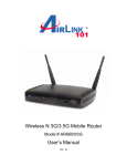
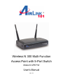
Wireless N 300 Multi-Function Access Point with 5-Port Switch Model # AP671W User’s Manual Ver. 1A Federal Communication Commission Interference Statement FCC Part 15 This equipment has been tested and found to comply with the limits for a Class B digital device, pursuant to Part 15 of FCC Rules. These limits are designed to provide reasonable protection against harmful interference in a residential installation. This equipment generates, uses, and can radiate radio frequency energy and, if not installed and used in accordance with the instructions, may cause harmful interference to radio communications. However, there is no guarantee that interference will not occur in a particular installation. If this equipment does cause harmful interference to radio or television reception, which can be determined by turning the equipment off and on, the user is encouraged to try to correct the interference by one or more of the following measures: 1. Reorient or relocate the receiving antenna. 2. Increase the separation between the equipment and receiver. 3. Connect the equipment into an outlet on a circuit different from that to which the receiver is connected. 4. Consult the dealer or an experienced radio technician for help. FCC Caution This equipment must be installed and operated in accordance with provided instructions and a minimum 20 cm spacing must be provided between computer mounted antenna and person’s body (excluding extremities of hands, wrist and feet) during wireless modes of operation. This device complies with Part 15 of the FCC Rules. Operation is subject to the following two conditions: (1) this device may not cause harmful interference, and (2) this device must accept any interference received, including interference that may cause undesired operation. Any changes or modifications not expressly approved by the party responsible for compliance could void the authority to operate equipment. Federal Communication Commission (FCC) Radiation Exposure Statement This equipment complies with FCC radiation exposure set forth for an uncontrolled environment. In order to avoid the possibility of exceeding the FCC radio frequency exposure limits, human proximity to the antenna shall not be less than 20cm (8 inches) during normal operation. The antenna(s) used for this transmitter must not be co-located or operating in conjunction with any other antenna or transmitter. The equipment version marketed in US is restricted to usage of the channels 1-11 only. 1 Table of Contents FEDERAL COMMUNICATION COMMISSION INTERFERENCE STATEMENT ........................................ 1 TABLE OF CONTENTS .................................................................................................................................. 2 CHAPTER 1 INTRODUCTION ....................................................................................................................... 3 1.1 FEATURES ...........................................................................................................................................................3 1.2 PACKAGE CONTENTS .........................................................................................................................................3 1.3 ACCESS POINT INTERFACE ................................................................................................................................4 CHAPTER 2 CONFIGURING THE ACCESS POINT .................................................................................... 6 2.1 INSTALLING THE ACCESS POINT TO YOUR NETWORK .......................................................................................6 2.2 ACCESSING THE ACCESS POINT BY WEB BROWSER ......................................................................................15 2.3 VIEW SYSTEM STATUS AND INFORMATION ......................................................................................................16 2.4 SELECT AN OPERATING MODE FOR ACCESS POINT........................................................................................18 2.4.1 AP Mode ..................................................................................................................................................19 2.4.1.1 Multiple ESSID ...................................................................................................................................................... 20 2.4.2 AP Client Mode.......................................................................................................................................22 2‐4‐2‐1 Wireless Site Survey............................................................................................................................................. 24 2.4.3 AP Bridge - Point to Point Mode ..........................................................................................................25 2.4.4 AP Bridge - Point to Multi-Point Mode.................................................................................................27 2.4.5 AP Bridge - WDS Mode.........................................................................................................................29 2.4.6 Universal Repeater ................................................................................................................................31 2.5 CONFIGURE WIRELESS SECURITY ...................................................................................................................34 2.5.1 WEP .........................................................................................................................................................35 2.5.2 WPA Pre-Shared Key............................................................................................................................37 2.5.3 WPA Radius............................................................................................................................................37 2.5.4 802.1x Authentication ............................................................................................................................38 2.6 SET UP MAC FILTERING ..................................................................................................................................40 2.7 CONFIGURE ADVANCED SETTINGS ..................................................................................................................42 2.8 CONFIGURE WPS SETTING .............................................................................................................................44 2.9 CONFIGURE RADIUS SERVER ...........................................................................................................................46 2.10 MANAGEMENT.................................................................................................................................................48 2.10.1 Change the password of the AP ........................................................................................................48 2.10.2 Change the IP Address of the AP......................................................................................................48 2.11 TOOLS .............................................................................................................................................................49 2.11.1 Backup and Restore the Configuration Settings .............................................................................49 2.11.2 Upgrade the Firmware for the Access Point ....................................................................................51 2.11.3 Reboot the Access Point.....................................................................................................................52 CHAPTER 3 TROUBLESHOOTING .............................................................................................................53 APPENDIX A - SPECIFICATION ..................................................................................................................54 TECHNICAL SUPPORT.................................................................................................................................55 2 Chapter 1 Introduction Congratulations on your purchase of AP671W, Airlink101 Wireless N 300 Multi-Function Access Point with 5-Port Switch! This product is ideal for home or SOHO users who need to add wireless capability to their existing wired network or extend the range for their wireless networks. This Access Point can function in 6 different modes: Access Point, AP Client, Universal Repeater, Point to Point and Point to Multi-Point Bridge, and WDS Bridge. With the bundled Airlink101® EZ Setup Wizard, you can simply follow the user-friendly UI and the configuration is as easy as few clicks without going through any hassle! The Wireless N technology that delivers data rate of up to 300Mbps* provides higher bandwidth and boarder coverage than Wireless G. You can also create a local area network easily for file sharing with the built-in 5-Port 10/100Mbps switch. A full range of security features such as WEP, WPA-PSK, and WPA2-PSK provide the highest level of wireless network security. Best of all, AP671W works with IEEE 802.11 b/g/n network devices, which ensures compatibility with your existing network products. 1.1 Features • • • • • • • • Highest data rate of up to 300Mbps* with IEEE 802.11n standard 6-in-1 Multi-Function: Access Point, Universal Repeater, AP Client, Point-to-Point and Point-to-Multi Point Bridge, WDS (Wireless Distributed System) Multiple-SSID function supports 4 separate wireless networks for different user groups WPA2, WPA advanced wireless security and RADIUS server Easy Setup Button (WPS) for easy connection to existing wireless devices Simple configuration with bundled EZ Setup Wizard Fully backward compatible with 802.11b/g Works best with Airlink101® Wireless N products 1.2 Package Contents Before you start to use this router, please check if there’s anything missing in the package, and contact your dealer of purchase to claim for missing items: • • • • • Wireless N 300 Multi-Function Access Point Setup CD Quick Installation Guide Power Adapter RJ-45 Ethernet Cable 3 1.3 Access Point Interface Front Panel LEDs LED Light Status Description POWER On Router is powered on. On WPS setup is in progress. Off Wireless network is switched off. Flashing Wireless network is ready and WPS setup is not in progress. On LAN port is connected. Off LAN port is not connected. Flashing LAN port is transferring or receiving data. WLAN LAN 1-5 LNK/ACT Back Panel Item Name Description Antenna Two 3dBi dipole antennas. Radio ON/OFF Switch the button to activate or deactivate the Router’s wireless function. Reset / WPS • Reset: Press this button and hold for 10 seconds to restore all settings to factory defaults. • WPS: Press this button for no longer than 1 second to start wireless security synchronization with clients. 4 1~5 Local Area Network (LAN) ports 1 to 5. Power Power connector DC 12V/1A, connects to A/C power adapter. 5 Chapter 2 Configuring the Access Point 2.1 Installing the Access Point to Your Network Step 1 Insert the provided CD into your computer’s CD ROM drive. You will be using this computer to configure the AP. Step 2 Click Next to start the configuration. Step 3 Connect one end of a network cable to the WAN port of the router and connect the other end of the cable to the DSL/Cable modem. Power on the modem. Click Next. 6 A. Connect the AP to the Router B. Power on the AP 7 Step 4 Make sure the LEDs of POWER, WLAN and the LAN that is connected to the Router are lit. If not, try the above steps again. Step 5 Enter the AP’s password to log in to the AP. The default password is “admin”. It is recommended to change the AP’s password to protect your network security. Please enter a new password into “New Password” and “Confirm New Password”. If you do not wish to change the current password, please leave them blank. Click Log In. Step 6 Assign a valid IP Address/Subnet Mask and Default Gateway for your AP. This setting must match with your wireless network. You will use this IP address to access the AP’s Webbased Configuration Utility for more advanced features. 8 Step 7 Select an operation mode for your Access Point and click Next. Step 8 Configure the settings for the operation mode you have selected. A) Access Point Configure the SSID and Channel Number if you have selected Access Point mode. Click Next. Check on Enable the WPA/WPA2 (Mixed) and enter 8~63 characters into Pre-Shared Key. This is the security key for your wireless network. Click Next. 9 B) Universal Repeater Click on Site Survey, select the wireless router or AP you wish to repeat on the popup Wireless Site Survey window and click Connect. Configure a network name in Main SSID for the repeater to be identified. 10 Wireless Site Survey Configure wireless security settings according to the root AP’s settings. The Security Key you enter must match with the one of root AP. Click Next. C) AP Client Click on Site Survey, select the wireless router or AP you wish to connect on the popup Wireless Site Survey window or enter your wireless network’s SSID manually. Click Next. 11 Enter the key of the wireless network you wish to connect to. Click Next. D) Point-to-Point / Point-to-MultiPoint / WDS Bridge Same setup procedure applies to Point-to-Point Bridge, Point-to-MultiPoint Bridge and WDS Bridge modes. For bridge mode, you need at least two Access Points. We will use Point-toPoint Bridge as an example. Select a channel number you wish to use and enter the MAC address of the other Access Point for the bridge. Click Next. 12 Configure the wireless security settings. It is recommended to use WPA2-PSK(AES) which is the safest encryption for general users. Click Next. After finishing the setup of the first AP, you need to follow the same configuration procedure on other Access Point(s). Step 9 Verify the settings you have configured and click Restart. Wait for 60 second for the AP to restart. 13 Step 10 Click Finish to end the EZ Setup Wizard. After the AP is restarted, it is ready to use. To configure more advanced features, please go to the next section. 14 2.2 Accessing the Access Point by Web Browser The EZ Setup Wizard will guide you through the basic configuration for the Access Point. For more advanced settings, you will need to link to the Access Point’s Web-based Configuration Utility. Step 1 Open the web browser (i.e. Internet Explorer or Mozilla Firefox) and type 192.168.2.250 or the IP address you have configured for your Access Point (the IP address you entered in Step 6, Section 2.1) in the URL address bar and press Enter. Step 2 Log in to the Access Point with username “admin” and password. The Web Configuration Utility contains advanced features that allow you to configure the AP to meet your network’s needs such as: MAC Filter, Multiple AP, Radius Server, etc. Below is a general description of the functions available for this Access Point. Menu Description Status Displaying the system status and information of this Access Point Basic Settings Selecting an operation mode for this Access Point and configuring its corresponding settings. Security Configuring the wireless security settings for the Access Point. MAC Filter Configuring the MAC address filter to protect your network from being accessed by unauthorized users and highly increase the security for your personal data. Advanced Settings Configuring the advanced network settings for this Access Point. WPS Setting Using the WiFi-Protected Setup (WPS) to make the connection to the wireless clients easier. Radius Server Allowing you to configure a Radius Authorization Server on this Access Point. Management Allowing you to change the administrator’s password and IP address. Tools Allowing you to back/restore the AP’s settings, upgrade the firmware, and reboot the AP remotely. 15 2.3 View System Status and Information After you connected to the access point by web browser, the first thing you see is ‘Status and Information’ page. All system and network related information of this access point will be displayed here. The information is very helpful when you want to know the detailed information of your access point, and when you try to fix the communication problem between this access point and other wired / wireless computer / devices. You can click ‘Status’ on the left, and the system status and information will be displayed, as shown below: Here are descriptions of every item: Mode Displays current wireless operating mode (see next Section) . ESSID Displays current ESSID (the name used to identify this wireless access point). Channel Number Security Displays current wireless channel number. BSSID Displays current BSSID (a set of unique identification name of this access point, it can not be modified by user). Displays current wireless security setting. 16 Associated Clients Displays the number of connected wireless client. IP Address Displays the IP address of this wireless access point. Subnet Mask Displays the Subnet mask of IP address. Default Gateway Displays the IP address of default gateway. MAC address Displays the MAC address of the AP. Up time Displays the total passed time since the wireless access point is powered. Hardware Version Displays the hardware version. Firmware Version Displays the current firmware version. If you want to perform firmware upgrade, this number will help you to determine if you need such upgrade. 17 2.4 Select an Operating Mode for Access Point This access point can be operated in different modes; you can click ‘Basic Setting’ on the left of web management interface to select an operating mode you want to meet for different needs: You can click ‘Mode’ dropdown menu to select operating mode, and there are 6 operating modes available: AP Add wireless capability to the existing wired network by connecting the AP to a wired router/switch. AP-Client Enable the Ethernet device such us TV and Game console connected to the access point to a wireless client. AP Bridge-Point to Point Connect two physically isolated wireless networks with two wireless access points. Both access points must be configured to the same mode. You will need two AP671W for this mode. The AP can only be connected by another AP in this mode wirelessly. AP Bridge-Point to Multi-Point Connect four physically isolated wireless networks with four wireless access points. Every access point must be configured to the same mode. You will need four AP671W for this mode. The AP can only be connected by other APs in this mode wirelessly. AP Bridge-WDS This mode is similar to ‘AP Bridge to Multi-Point’, but access point is not working in bridge-dedicated mode. Bridge-WDS mode will be able to accept wireless clients while the access point is working as a wireless bridge. Universal Repeater This product can act as a wireless range extender that will help you to extend the range of your wireless network. The access point can act as Station and AP at the same time. It can use Station function to connect to a Root AP and use AP function to service all wireless clients within its coverage. 18 Please select one wireless operating mode, for detailed descriptions of every operating mode; please refer to Section 2.4.1 to 2.4.6 listed below. 2.4.1 AP Mode In AP mode, this access point acts as a bridge between 802.11b/g/Draft-N wireless devices and wired Ethernet network, and exchanges data between them. Diagram 1: AP mode application When you select ‘AP’, the following options will be displayed: Here are descriptions of every setup item: 19 Band Please select the wireless band you wish to use. By selecting different band setting, you’ll be able to allow or deny the wireless client of a certain band. If you select 2.4GHz (B), 2.4GHz (N), or 2.4GHz (G), only wireless clients using the wireless band you select (802.11b, 802.11 Draft-N, or 802.11g) will be able to connect to this access point. If you select 2.4GHz (B+G), then only wireless clients using 802.11b and 802.11g band will be able to connect to this access point. If you want to allow 802.11b, 802.11g, and 802.11 Draft-N clients to connect to this access point, select 2.4GHz (B+G+N). Main ESSID Please input the ESSID (the name used to identify this wireless access point) here. You can input up to 32 alphanumerical characters. PLEASE NOTE THAT ESSID IS CASE SENSITIVE. Multiple ESSID The access point supports multiple SSID function; up to 3 SSIDs can be set. If you want to configure additional SSIDs, please click this button. For detailed descriptions of the function, please refer to Section 2.4.1.1. Channel Number Please select a channel number you wish to use. If you know a certain channel number is being used by other wireless access points nearby, please refrain from using the same channel number Associated Clients Click ‘Show Active Clients’ button and a new popup window will appear which contains the information about all wireless clients connected to this access point. You can click ‘Refresh’ button in popup window to keep information up-to-date. After you finish with setting, please click ‘Apply’, and the following message will be displayed: After you clicked Apply, the following message will be displayed on your web browser: You can click “Continue” to back to previous setup page to continue on other setup procedures, or click “Apply” to reboot the router so the settings will take effect (Please wait for 30 seconds while router is rebooting). 2.4.1.1 Multiple ESSID 20 This access point supports 4 sets of SSID. Besides the main SSID (It can be configure in Basic Setting page), you can configure another three SSIDs here. With different SSIDs, you can separate the wireless networks with different SSID name, wireless security, WMM, and VLAN settings. NOTE: If you want to configure the wireless security for different SSID, please go to ‘2.5 Wireless Security’ for more information. Here are descriptions of every setup item: No. Except Main SSID, you can configure additional three ESSID here. Enable Select the box to enable each additional ESSID. SSID Please input the SSID name (the name used to identify this wireless access point) here. You can input up to 32 alphanumerical characters. PLEASE NOTE THAT ESSID IS CASE SENSITIVE. Broadcast SSID Decide if the wireless access point will broadcast its own ESSID or not. You can hide the ESSID of your wireless access point (set the option to ‘Disable’), so only people those who know the ESSID of your wireless access point can get connected. 21 WMM WMM (Wi-Fi Multimedia) technology, which can improve the performance of certain network applications, like audio/video streaming, network telephony (VoIP), and others. When you enable WMM function, the access point will define the priority of different kinds of data, to give higher priority to applications which require instant responding. Therefore you can improve the performance of such network applications. VLAN ID (0:Untagged) If your network uses VLANs, you can assign the SSID to a VLAN on your network. Client devices that associate using the SSID are grouped into this VLAN. The VLAN ID range is from 1 to 4094. The VLAN ID is 0 by default, it means that disable the VLAN function for the ESSID. 2.4.2 AP Client Mode In this mode, you can connect the access point to Ethernet device such us TV and Game player to enable the Ethernet device be a wireless station and join to a wireless network through an access point or AP router. Diagram 2: AP Client mode application NOTE: You need to configure the wireless security if the wireless station you are connecting to has security enabled. Please go to ‘Security’ to configure the settings according to the security settings of the station you are connecting to. Please refer to ‘2.5 Wireless Security’ for more information. When you select ‘AP Client’, the following options will be displayed: 22 Here are descriptions of every setup item: Band Please select the wireless band you wish to use. By selecting different band setting, you’ll be able to allow or deny the wireless client of a certain band. If you select 2.4GHz (B), 2.4GHz (N), or 2.4GHz (G), only wireless clients using the wireless band you select (802.11b, 802.11 Draft-N, or 802.11g) will be able to connect to this access point. If you select 2.4GHz (B+G), then only wireless clients using 802.11b and 802.11g band will be able to connect to this access point. If you want to allow 802.11b, 802.11g, and 802.11 Draft-N clients to connect to this access point, select 2.4GHz (B+G+N). Main ESSID Please input the ESSID (the name used to identify this wireless access point) here. You can input up to 32 alphanumerical characters. PLEASE NOTE THAT ESSID IS CASE SENSITIVE. Site Survey When you use this access point as a wireless station for Ethernet network device to have wireless capability, you have to associate it with a working access point. Click ‘Select Site Survey’ button, then a “Wireless Site Survey Table” will pop up. It will list all available access points near by. You can select one access point in the table and it will join wireless LAN through this access point. Please go to Section 2.4.2.1 for more information about the ‘Wireless Site Survey Table’. After you finish with setting, please click ‘Apply’, and the following message will be displayed: After you clicked Apply, the following message will be displayed on your web browser: You can click “Continue” to back to previous setup page to continue on other setup 23 procedures, or click “Apply” to reboot the router so the settings will take effect (Please wait for 30 seconds while router is rebooting). 2421 Wireless Site Survey The table will list the access points nearby as the access point is set to Station mode; you can select one of the access points to associate. Here are descriptions of every setup item: Select Click the radio button to select the access point. Channel Display to channel number of the access point. SSID Display the SSID name of the access point. BSSID Display the BSSID (MAC Address) of the access point. Encryption Display the encryption setting of the access points. If you have selected the access point with security setting, you have to go to ‘2-7 Wireless Security’ to set the same security with the access point you want to associate. Authentication Display the authentication type of the access point. Signal The signal strength of each access point will be displayed here. The signal strength is stronger, the connection quality is better. 24 Mode Display the wireless modes include 11b, 11b/g or 11b/g/n or 11n only of the access points. Refresh Click this button to refresh the table. Connection Select an access point and click this button to choose the network. The SSID name of the access point you have selected will be displayed in the Main SSID in the Basic Setting page. 2.4.3 AP Bridge - Point to Point Mode In this mode, this wireless access point will connect to another AP671W Wireless N 300 Access Point which uses the same mode, and all wired Ethernet clients of both wireless access points will be connected together. You can use this mode to connect a network to another network which is physically isolated. Please note that when you set your access point to this mode, it will not accept regular wireless clients anymore. Diagram 3: Point to Point Bridge mode application When you select ‘AP Bridge - Point to Point’, the following options will be displayed: 25 Here are descriptions of every setup item: Band Please select the wireless band you wish to use. By selecting different band setting, you’ll be able to allow or deny the wireless client of a certain band. If you select 2.4GHz (B), 2.4GHz (N), or 2.4GHz (G), only wireless clients using the wireless band you select (802.11b, 802.11 Draft-N, or 802.11g) will be able to connect to this access point. If you select 2.4GHz (B+G), then only wireless clients using 802.11b and 802.11g band will be able to connect to this access point. If you want to allow 802.11b, 802.11g, and 802.11 Draft-N clients to connect to this access point, select 2.4GHz (B+G+N). Channel Number Please select a channel number you wish to use. The channel number must be same with another wireless access point you wish to connect. MAC address 1 Please input the MAC address of the wireless access point you wish to connect. Set Security Click this button to select an encryption mode for this wireless link, a new popup window will appear. Please refer to Section 2.5 for detailed descriptions. After you finish with setting, please click ‘Apply’, and the following message will be displayed: After you clicked Apply, the following message will be displayed on your web browser: 26 You can click “Continue” to back to previous setup page to continue on other setup procedures, or click “Apply” to reboot the router so the settings will take effect (Please wait for 30 seconds while router is rebooting). 2.4.4 AP Bridge - Point to Multi-Point Mode In this mode, this wireless access point will connect to up to four wireless access points which uses the same mode, and all wired Ethernet clients of every wireless access points will be connected together. You can use this mode to connect a network to other networks which is physically isolated. Please note that when you set your access point to this mode, it will not accept regular wireless clients anymore. Diagram 4: Point to Multi‐Point Bridge mode application When you select ‘AP Bridge-Point to Multi-Point’, the following options will be displayed: 27 Here are descriptions of every setup item: Band Please select the wireless band you wish to use. By selecting different band setting, you’ll be able to allow or deny the wireless client of a certain band. If you select 2.4GHz (B), 2.4GHz (N), or 2.4GHz (G), only wireless clients using the wireless band you select (802.11b, 802.11 Draft-N, or 802.11g) will be able to connect to this access point. If you select 2.4GHz (B+G), then only wireless clients using 802.11b and 802.11g band will be able to connect to this access point. If you want to allow 802.11b, 802.11g, and 802.11 Draft-N clients to connect to this access point, select 2.4GHz (B+G+N). Channel Number Please select a channel number you wish to use. The channel number must be same with another wireless access point you wish to connect. MAC address 1~4 Please input the MAC address of the wireless access point you wish to connect. Set Security Click this button to select an encryption mode for this wireless link, a new popup window will appear. Please refer to Section 2-7 for detailed descriptions. After you finish with setting, please click ‘Apply’, and the following message will be displayed: After you clicked Apply, the following message will be displayed on your web browser: 28 You can click “Continue” to back to previous setup page to continue on other setup procedures, or click “Apply” to reboot the router so the settings will take effect (Please wait for 30 seconds while router is rebooting). 2.4.5 AP Bridge - WDS Mode In this mode, this wireless access point will connect to up to four wireless access points which uses the same mode, and all wired Ethernet clients of every wireless access points will be connected together. You can use this mode to connect a network to other networks which is physically isolated. When you use this mode, this access point is still able to accept wireless clients. 29 Diagram 5: WDS Bridge mode application When you select ‘AP Bridge-WDS’, the following options will be displayed: Here are descriptions of every setup item: Band Please select the wireless band you wish to use. By selecting different band setting, you’ll be able to allow or deny the wireless client of a certain band. If you select 2.4GHz (B), 2.4GHz (N), or 2.4GHz (G), only wireless clients using the wireless band you select (802.11b, 802.11 Draft-N, or 802.11g) will be able to connect to this access point. If you select 2.4GHz (B+G), then only wireless clients using 802.11b and 802.11g band will be able to connect to this access point. If you want to allow 802.11b, 802.11g, and 802.11 Draft-N clients to connect to this access point, select 2.4GHz (B+G+N). MAIN ESSID Please input the ESSID (the name used to identify this wireless access point) here. You can input up to 32 alphanumerical characters. PLEASE NOTE THAT ESSID IS CASE SENSITIVE. Multiple ESSID The access point supports multiple SSID function; up to 3 SSIDs can be set. If you want to configure additional SSIDs, please click this button. For detailed descriptions of the function, please refer to Section 2.4.1.1. Channel Number Please select a channel number you wish to use. The channel number must be same with another wireless access point you wish to connect. 30 Associated Clients Click ‘Show Active Clients’ button and a new popup window will appear which contains the information about all wireless clients connected to this access point. You can click ‘Refresh’ button in popup window to keep information up-to-date. MAC address 1~4 Please input the MAC address of the wireless access point you wish to connect. Set Security Click this button to select an encryption mode for this wireless link, a popup window will appear. Please refer to Section 2.5 for detailed descriptions. After you finish with setting, please click ‘Apply’, and the following message will be displayed: After you clicked Apply, the following message will be displayed on your web browser: You can click “Continue” to back to previous setup page to continue on other setup procedures, or click “Apply” to reboot the router so the settings will take effect (Please wait for 30 seconds while router is rebooting). 2.4.6 Universal Repeater In this mode, the access point can act as a wireless repeater; it can be Station and AP at the same time. It can use Station function to connect to a Root AP and use AP function to service all wireless stations within its coverage. 31 Diagram 5: Repeater mode application When you select ‘Universal Repeater, the following options will be displayed: Here are descriptions of every setup item: 32 Band Please select the wireless band you wish to use. By selecting different band setting, you’ll be able to allow or deny the wireless client of a certain band. If you select 2.4GHz (B), 2.4GHz (N), or 2.4GHz (G), only wireless clients using the wireless band you select (802.11b, 802.11 Draft-N, or 802.11g) will be able to connect to this access point. If you select 2.4GHz (B+G), then only wireless clients using 802.11b and 802.11g band will be able to connect to this access point. If you want to allow 802.11b, 802.11g, and 802.11 Draft-N clients to connect to this access point, select 2.4GHz (B+G+N). MAIN SSID Please input the ESSID (the name used to identify this wireless access point) here. You can input up to 32 alphanumerical characters. PLEASE NOTE THAT ESSID IS CASE SENSITIVE. Multiple ESSID The access point supports multiple SSID function; up to 3 SSIDs can be set. If you want to configure additional SSIDs, please click this button. For detailed descriptions of the function, please refer to Section 2.4.1.1. Channel Number Please select a channel number you wish to use. The channel number must be same with another wireless access point you wish to connect. Associated Clients Click ‘Show Active Clients’ button and a new popup window will appear which contains the information about all wireless clients connected to this access point. You can click ‘Refresh’ button in popup window to keep information up-to-date. Root AP SSID In ‘Universal Repeater’ mode, this device can act as a station to connect to a Root AP. You should assign the SSID of the Root AP here or click ‘Select Site Survey’ button to choose a Root AP. Select Site Survey Click ‘Select Site Survey’ button, then a “Wireless Site Survey Table” will pop up. It will list all available access points near by. You can select one access point in the table and the access point will join wireless LAN through this access point. Please go to Section 2.4.2.1 for more information about the ‘Wireless Site Survey Table’. After you finish with all settings, please click “Apply” button. If you want to reset all settings in this page, please click “Cancel” button. After you clicked Apply, the following message will be displayed on your web browser: 33 You can click “Continue” to back to previous setup page to continue on other setup procedures, or click “Apply” to reboot the router so the settings will take effect (Please wait for about 30 seconds while router is rebooting). 2.5 Configure Wireless Security This wireless access point provides many types of wireless security (wireless data encryption). When you use data encryption, data transferred by radio signals in the air will become unreadable for those people who don’t know correct encryption key (encryption password). There are two ways to set wireless security: 1. Click ‘Security’ on the left of web management interface. 34 2. Click ‘Set Security’ button when the wireless operating mode you selected is ‘AP Bridge-Point to Point’, ‘AP Bridge-Point to Multi-Point’, or ‘AP Bridge-WDS’. There are four types of security level you can select: Disable (no security - data encryption disabled), WEP, WPA Pre-shared Key, and WPA Radius. Please refer to the following sections for detailed instructions. NOTE: If you have enabled Multiple SSID function, please select the SSID network you wish to configure in advance. Please remember it’s very important to set wireless security settings properly! Without a proper setting, hackers and intruders may gain access to your local network and do something bad to your computers and servers, which could cause serious problem. There are several things you can do to improve wireless security: 1. Always enable data encryption. Only disable it when you want to open your wireless access point to the public. 2. Never use simple words as encryption password. Use the random combination of symbols, numbers, and alphabets will greatly improve security. 3. Use WPA when possible - it's much safer than WEP. 4. Change encryption password when you’ve used it for too long time. 2.5.1 WEP WEP (Wired Equivalent Privacy) is a common encryption mode, it’s safe enough for home and personal use. But if you need higher level of security, please consider using WPA encryption (see next Section). However, some wireless clients don’t support WPA, but only support WEP, so WEP is still a good choice for you if you have such kind of client in your network environment. When you select ‘WEP’ as encryption type, the following page will be displayed: 35 Here are descriptions of every setup item: Key Length There are two types of WEP key length: 64-bit and 128-bit. Using ‘128-bit’ is safer than ’64-bit’, but will reduce some data transfer performance. Key Format There are two types of key format: ASCII and Hex. When you select a key format, the number of characters of key will be displayed. For example, if you select ’64-bit’ as key length, and ‘Hex’ as key format, you’ll see the message at the right of ‘Key Format’ is ‘Hex (10 characters), which means the length of WEP key is 10 characters. Default Tx Key You can set up to four sets of WEP key, and you can decide which key is being used by default here. If you don’t know which one you should use, select ‘Key 1’. Encryption Key 1 to 4 Input WEP key characters here, the number of characters must be the same as the number displayed at ‘Key Format’ field. You can use any alphanumerical characters (0-9, a-z, and A-Z) if you select ‘ASCII’ key format, and if you select ‘Hex’ as key format, you can use characters 0-9, a-f, and A-F. You must enter at least one encryption key here, and if you entered multiple WEP keys, they should not be same with each other. Enable 802.1x Authentication Check this box to enable 802.1x user authentication. Please refer to Section 2-7-5 for detailed instructions. 36 2.5.2 WPA Pre-Shared Key WPA Pre-Shared key is the safest encryption method currently, and it’s recommended to use this encryption method to ensure the safety of your data. When you select ‘WPA pre-shared key’ as encryption type, the following page will be displayed: Here are descriptions of every setup item: WPA Unicast Cipher Suite Available options are: WPA (TKIP), WPA2 (AES), and WPA2 Mixed. It is suggested to select WPA2 (AES) but you have to make sure your wireless clients support the cipher you selected. WPA2 Mixed supports both WPA and WPA2. If some of your wireless client supports WPA but not WPA2, you can select this cipher. Pre-shared Key Format Please select the format of pre-shared key here, available options are ‘Passphrase’ (8 to 63 alphanumerical characters) and ‘Hex (64 hexadecimal characters – 0 to 9 and a to f). Pre-shared Key Please input a key value according to the key format you selected here. For security reason, don’t use simple words). 2.5.3 WPA Radius WPA Radius is the combination of WPA encryption method and RADIUS user authentication. If you have a RADIUS authentication server, you can check the identity of every wireless client by user database. When you select ‘WPA RADIUS’ as encryption type, the following page will be displayed: 37 Here are descriptions of every setup item: WPA Unicast Cipher Suite You can select WPA encryption type here. AES is safer than TKIP, but not every wireless client supports it. Please refer to the specification of your wireless client to decide which encryption type you should use. Use internal MD5/PEAP RADIUS Server Uses built-in RADIUS Server (refer to Section 2-8) instead of external RADIUS server. If you check this box, the value in following three fields will be ignored. RADIUS Server IP address Please input the IP address of RADIUS authentication server here. RADIUS Server Port Please input the port number of RADIUS authentication server here. Default value is 1812. RADIUS Server Password Please input the password of RADIUS authentication server here. 2.5.4 802.1x Authentication You can enable 802.1x user identification (based on RADIUS user authentication server) by checking ‘Enable 802.1x Authentication’ box when you select ‘Disable’ or ‘WEP’ as encryption type, and the following page will be displayed: 38 Here are descriptions of every setup item: Use internal MD5/PEAP RADIUS Server Uses built-in RADIUS Server (refer to next Section) instead of external RADIUS server. If you check this box, the value of internal RADIUS server fields will be ignored. Enable 802.1x Authentication Enable or disable the use of 802.1x user authentication. RADIUS Server IP address Please input the IP address of RADIUS authentication server here. RADIUS Server Port Please input the port number of RADIUS authentication server here. Default value is 1812. RADIUS Server Password Please input the password of RADIUS authentication server here. After you finish with setting, please click ‘Apply’, and the following message will be displayed: After you clicked Apply, the following message will be displayed on your web browser: You can click “Continue” to back to previous setup page to continue on other setup procedures, or click “Apply” to reboot the router so the settings will take effect (Please wait for 30 seconds while router is rebooting). 39 2.6 Set Up MAC Filtering Another security measure you can use to keep hackers and intruders away is ‘MAC filtering’. You can pre-define a so-called ‘white-list’, which contains MAC addresses of the wireless clients you trust. All other wireless client with the MAC address which is not in your list will be denied by this wireless access point. To set up MAC filtering, please click ‘MAC Filtering’ on the left menu and the following page will be displayed: Address Filtering Table (1) Add New Entry Here (2) This page contains two parts of MAC filtering information. All allowed MAC addresses will be listed in upper part (1), and you can add new MAC addresses by components in lower part (2). Here are descriptions of every setup item: Select Check this box to select one or more MAC address(es) to delete. Delete Selected Click this button to delete all selected MAC address(es). Delete All Delete all MAC address entries. Reset Uncheck all selected MAC address entries. Enable Wireless Access Control Check this box to enable MAC address restriction, if unchecked, no restriction will be enforced (any wireless client with proper encryption setting will be able to connect to this wireless access point). 40 MAC address Input MAC address allowed using this wireless access point here. You don’t have to add colon (:) or hyphen (-) by yourself, just input 0 to 9 and a to f here, like 112233445566 or aabbccddeeff. Comment You can input any text here as the comment of this MAC address, like ‘ROOM 2A Computer’ or anything. You can input up to 16 alphanumerical characters here. This is optional and you can leave it blank, however, it’s recommended to use this field to write a comment for every MAC addresses as a memory aid. This is optional. Add When you finish inputting MAC address and (optional) Comment, click this button to add the MAC address to the list. Clear Remove all characters in ‘MAC address’ and ‘Comments’ field. After you finish with setting, please click ‘Apply’, and the following message will be displayed: When you see this message, the settings you made is successfully save. You can click ‘Continue’ button to back to previous page and continue on other setting items, or click ‘Apply’ button to restart the wireless access point and the changes will take effect after about 30 seconds. 41 2.7 Configure Advanced Settings This wireless access point has many advanced wireless features. Please note that all settings listed here are for experienced users only, if you’re not sure about the meaning and function of these settings, please don’t modify them, or the wireless performance might be reduced. You can click ‘Advanced Settings’ on the left menu to enter advanced settings menu, and the following page will be displayed: Here are descriptions of every setup item: Fragment Threshold Set the Fragment threshold of wireless radio. Do not modify default value if you don’t know what it is, default value is 2346. RTS Threshold Set the RTS threshold of wireless radio. Do not modify default value if you don’t know what it is, default value is 2347. Beacon Interval Set the beacon interval of wireless radio. Do not modify default value if you don’t know what it is, default value is 100. DTIM Period Set the DTIM period of wireless radio. Do not modify default value if you don’t know what it is, default value is 3. Data Rate Set the wireless data transfer rate to a certain value. Since most of wireless devices will negotiate with each other and pick a proper data transfer rate automatically, it’s not necessary to change this value unless you know what will happen after modification. 42 N Data Rate Set the data rate of 802.11 Draft-N clients, available options are MCS 0 to MCS 15, it’s safe to set this option to ‘Auto’ and it’s not necessary to change this value unless you know what will happen after modification. Channel Width Select wireless channel width (bandwidth taken by wireless signals of this access point). It’s suggested to select ‘Auto 20/40MHz’. Do not change to ’20 MHz’ unless you know what it is. Preamble Type Set the type of preamble of wireless radio, Do not modify default value if you don’t know what it is, default setting is ‘Short Preamble’. Broadcast ESSID Decide if the wireless access point will broadcast its own ESSID or not. You can hide the ESSID of your wireless access point (set the option to ‘Disable’), so only people those who know the ESSID of your wireless access point can get connected. WMM WMM (Wi-Fi Multimedia) technology, which can improve the performance of certain network applications, like audio/video streaming, network telephony (VoIP), and others. When you enable WMM function, the access point will define the priority of different kinds of data, to give higher priority to applications which require instant responding. Therefore you can improve the performance of such network applications. CTS Protect Enabling this setting will reduce the chance of radio signal collisions between 802.11b and 802.11g wireless access points. It’s recommended to set this option to ‘Auto’. TX Power You can set the output power of wireless radio. Unless you’re using this wireless access point in a really big space, you may not have to set output power to 100%. This will enhance security (malicious / unknown users in distance will not be able to reach your wireless access point). After you finish with setting, please click ‘Apply’, and the following message will be displayed: When you see this message, the settings you made is successfully save. You can click ‘Continue’ button to back to previous page and continue on other setting items, or click ‘Apply’ button to restart the wireless access point and the changes will take effect after about 30 seconds. 43 2.8 Configure WPS Setting Wi-Fi Protected Setup (WPS) is the simplest way to build connection between wireless network clients and this access point. You don’t have to select encryption mode and input a long encryption passphrase every time when you need to set up a wireless client, you only have to press a button on wireless client and this access point, and the WPS will do the setup for you. This access point supports two types of WPS: Push-Button Configuration (PBC), and PIN code. If you want to use PBC, you have to switch this access point to WPS mode and push a specific button on the wireless client to start WPS mode. You can push Reset/WPS button of this access point, or click ‘Start PBC’ button in the web configuration interface to do this; if you want to use PIN code, you have to provide the PIN code of the wireless client you wish to connect to this access point and then switch the wireless client to WPS mode. The detailed instructions are listed follow: Note: WPS function of this access point will not work for those wireless clients do not support WPS. To use WPS function to set encrypted connection between this access point and WPS-enabled wireless client by WPS, click ‘WPS Setting’ on the left of web management menu, and the following information will be displayed: Here are descriptions of every setup item: Enable WPS Check this box to enable or disable WPS function. 44 Wi-Fi Protected Setup Information All information related to WPS will be displayed here, they’re helpful when you’re setting up connections by WPS. WPS Status: Displays WPS status. If data encryption settings of this access point has never been set, ‘unConfigured’ message will be displayed her. (see Section 2-7 for detailed information); if data encryption settings has been set before, ‘Configured’ message will be displayed here. Self PinCode: This is the WPS PIN code of this access point. This code is useful when you need to build wireless connection by WPS with other WPS-enabled wireless devices. SSID: Displays the SSID (ESSID) of this access point. Authentication Mode: The wireless security authentication mode of this access point will be displayed here. If you don’t enable security function of the access point before WPS is activated, the access point will auto set the security to WPA (AES) and generate a set of passphrase key for WPS connection. Config Mode Start PBC Start PIN Passphrase Key: Displays the WPA passphrase here, all characters will be replaced by asterisk for security reason. If encryption is not set on this access point, nothing will be displayed here. There are ‘Registrar’ and ‘Enrollee’ modes for the WPS connection. When ‘Registrar’ is enabled, the wireless clients will follow the access point’s wireless settings for WPS connection. When ‘Enrolle’ mode is enabled, the access point will follow the wireless settings of wireless client for WPS connection. Click ‘Start PBC’ to start Push-Button style WPS setup procedure. This access point will wait for WPS requests from wireless clients for 2 minutes. The ‘WLAN’ LED on the access point will be steady on for 2 minutes when this access point is waiting for incoming WPS request. Please input the PIN code of the wireless client you via client wish to connect, and click ‘Start PIN’ button. The ‘WLAN’ LED on the access point will be steady on when this access point is waiting for incoming WPS request. NOTE: When you’re using PBC type WPS setup, you must press ‘PBC’ button (hardware or software) of wireless client within 120 seconds; if you didn’t press PBC button of wireless client within this time period, please press ‘PBC’ button (hardware or software) of this access point again. 45 2.9 Configure Radius Server Comparing to other wireless security measures, radius server provides user-based authentication. If your wireless client supports 802.1x user authentication, you can use the ‘Radius Server’ function to use the internal mini radius server to improve security and wireless user control. The internal radius server only supports 96 users and 16 IP addresses. If the number of user and/or IP address you need is more than this, please use external radius server. To set up internal radius server, click ‘Radius Server’ on the left of web management interface, and the following information will be displayed: Here are descriptions of every setup item: Enable Radius Server Check this box to enable internal Radius Server function. 46 User Profile If you want to enable the Radius Server on this AP, you need to configure a User Profile, a set of allowed users and their passwords here. Please input username, password, re-type password in corresponding field, and click ‘Add’ button to add the user to radius server database. You can click ‘Reset’ to clear the text you typed in above three fields. All current radius users will be listed here. If you want to delete one or more users, check ‘Select’ box of that user, and click ‘Delete Selected’ button; you can click ‘Delete All’ button to delete all users in radius server database. You can also click ‘Reset’ button to uncheck all ‘Select’ boxes. Authentication Client If you want to use the Radius Server on another Access Point/Wireless Router, you can configure this AP to be a radius client here. Please input Authenticator IP (the IP address of the AP/Wireless Router on which the Radius Server is enabled), secret key, re-type secret key in corresponding field, and click ‘Add’ button to add the IP address to radius server database. You can click ‘Reset’ to clear the text you typed in above three fields. All current IP addresses will be listed here. If you want to delete one or more addresses, check ‘Select’ box of that address, and click ‘Delete Selected’ button; you can click ‘Delete All’ button to delete all addresses in radius server database. You can also click ‘Reset’ button to uncheck all ‘Select’ boxes. After you finish with setting, please click ‘Apply’, and the following message will be displayed: When you see this message, the settings you made is successfully save. You can click ‘Continue’ button to back to previous page and continue on other setting items, or click ‘Apply’ button to restart the wireless access point and the changes will take effect after about 30 seconds. 47 2.10 Management 2.10.1 Change the password of the AP You can change the administrator’s password used to enter the web configuration utility of this wireless access point. Please click ‘Management’ on the left, and the following page will be displayed: Please input current password in ‘Current Password’ field, then input new password in both ‘New Password’ and ‘Re-Enter Password’ field. 2.10.2 Change the IP Address of the AP You can change the IP address of this wireless access point, so it can become a part of your local network. Please remember this address or you will not be able to connect the configuration menu of this wireless access point. To change the IP address, please click ‘Management’ on the left, and the following page will be displayed: 48 Default IP address is: 192.168.2.250 / Subnet Mask 255.255.255.0, please configure the IP address to match your network setting and make sure this IP address is always unique on your network. You can press and hold ‘Reset/WPS’ button over 10 seconds to change the IP address back to default value if you forget the IP address you set. 2.11 Tools 2.11.1 Backup and Restore the Configuration Settings You can backup all configurations of this access point to a file for security reason or restore to a previously-configured status including factory default. To backup or restore access point configurations, please click ‘Tools’ on the left menu, and the following page will be displayed on your web browser: 49 Here are descriptions of every buttons: Backup Settings Press ‘Save’ button, and you’ll be prompted to download the configuration as a file; default filename is ‘config.bin’, you can save it as another filename for different versions, and keep it on your local hard drive. Restore Settings Press ‘Browse’ to pick a previously-saved configuration file from your computer, and then click ‘Upload’ to transfer the configuration file to access point. After the configuration is uploaded, the access point’s configuration will be replaced by the file you just uploaded. Restore to Factory Default Press ‘Reset’ button to remove all settings you made, and restore the access point back to factory default settings. 50 2.11.2 Upgrade the Firmware for the Access Point If there are new firmware versions of this wireless access point available, you can upgrade the firmware to the latest version to get extra functions or problem fixed. To perform firmware upgrade, please click ‘Tool’ on the left menu, and the following page will be displayed: Click ‘Browse’ button first, you’ll be prompted to provide the filename of firmware upgrade file. Please download the latest firmware file from our website, and use it to upgrade your access point. After a firmware upgrade file is selected, click ‘Apply’ button, and the access point will start firmware upgrade procedure automatically. The procedure may take several minutes, please be patient. NOTE: Never interrupt the upgrade procedure by closing the web browser or physically disconnect your computer from access point. If the firmware you uploaded is corrupt, the firmware upgrade will fail, and you may have to return this access point to the dealer of purchase to ask for help. (Warranty voids if you interrupted the upgrade procedure). 51 2.11.3 Reboot the Access Point When you think the access point is not working properly, you can use this function to restart the access point; this may help and solve the problem. This function is useful when the access point is far from you or unreachable. However, if the access point is not responding, you may have to switch it off by unplug the power plug and plug it back again after 10 seconds. To reset your access point, please click ‘Tools’ on the left menu, and the following page will be displayed: Please click ‘Reboot’ button, and a popup message will ask you again, to make sure you really want to reboot the access point: Click ‘OK’ to restart the access point, or click ‘Cancel’ to abort. Please remember all connections between wireless client and this access point will be disconnected. 52 Chapter 3 Troubleshooting If you found the access point is working improperly or stop responding to you, don’t panic! Before you contact your dealer of purchase for help, please read this troubleshooting first. Some problems can be solved by yourself within very short time! Scenario Solution Access point is not responding to me when I want to access it by web browser Please check the connection of power cord and network cable of this access point. All cords and cables should be correctly and firmly inserted to the access point. You must use the same IP address section which access point uses. Are you using MAC or IP address filter? Try to connect the access point by another computer and see if it works; if not, please perform a hard reset (pressing ‘reset’ button). Set your computer to obtain an IP address automatically (DHCP), and see if your computer can get an IP address. If you did a firmware upgrade and this happens, contact your dealer of purchase for help. If all above solutions don’t work, contact the dealer of purchase for help. Can’t get connected to wireless access point If encryption is enabled, please re-check WEP or WPA passphrase settings on your wireless client. Try to move closer to wireless access point. Unplug the power plug of access point, and plug it back again after 10 seconds. I can’t locate my access point by my wireless client ‘Broadcast ESSID’ set to off? Is Antenna properly installed and secured? Are you too far from your access point? Try to get closer. Please remember that you have to input ESSID on your wireless client manually, if ESSID broadcast is disabled. File download is very slow or breaks frequently Try to reset the access point and see if it’s better after that. Try to know what computers do on your local network. If someone’s transferring big files, other people will think Internet is really slow. Change channel number and see if this works. Access point become hot This is not a malfunction, if you can keep your hand on the access point’s case. If you smell something wrong or see the smoke coming out from access point or power adapter, please disconnect the access point and power adapter from utility power (make sure it’s safe before you’re doing this!), and call your dealer of purchase for help. 53 Appendix A - Specification Standards • • IEEE 802.11b/g/n Operation Mode • LEDs System Requirement 6-in-1: Access Point , Universal Repeater, AP Client, Point to Point and Point to Multi-Point Bridge WDS Bridge Antenna • 2 undetachable 3dBi dipole antennas 5 x 10/100Mbps Ethernet connector Security • WPA / WPA2 • WEP 64/128-bit encryption • Radius Server • Easy Setup Button (WPS) 11n: up to 300Mbps • 11b/g: 54, 48, 36, 24, 18, 12, 11, 9, 6, 5.5, 2, 1Mbps auto fallback Computer or network devices with wired or wireless network interface. • Web Browser • Recommended use with Airlink101 ® Wireless N products • 12V / 1A Dimensions • 174 x 103 x 30 mm Temperature • Operating: 0ºC to 40ºC Humidity • 10% to 95% Non-Condensing Warranty Data rate • • Power LAN Port • Power, WLAN, LAN1~5 • Limited 1-year warranty Certification • 54 FCC Technical Support E-mail: [email protected] Toll Free: 1-888-746-3238 Website: www.airlink101.com † The GPL open source code can be downloaded at http://www.airlink101.com/gpl/ *Theoretical maximum wireless signal rate derived from IEEE standard 802.11n specifications. Actual data throughput will vary. Network conditions and environmental factors, including volume of network traffic, building materials and construction, mix of wireless products used, radio frequency interference (e.g., cordless telephones and microwaves) as well as network overhead lower actual data throughput rate. Compatibility with 802.11n devices from other manufactures is not guaranteed. Specifications are subject to change without notice. Photo of product may not reflect actual content. All products and trademarks are the property of their respective owners. Copyright ©2010 Airlink101® 55