1
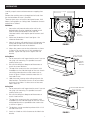
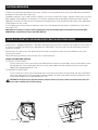
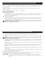
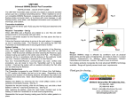
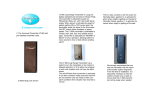
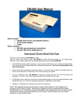
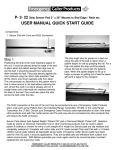
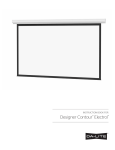
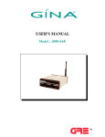
INSTRUCTION BOOK
FOR TENSIONED SCREEN
IMPORTANT SAFETY INSTRUCTIONS
When using your video equipment, basic safety precautions
should always be followed, including the following:
1. Read and understand all instructions before using.
2. Position the cord so that it will not be tripped over, pulled,
or contact hot surfaces.
3. If an extension cord is necessary, a cord with a current
rating at least equal to that of the appliance should be used.
Cords rated for less amperage than the appliance may
overheat.
4. To reduce the risk of electric shock, do not disassemble this
appliance. Contact an authorized service dealer when repair
work is required. Incorrect reassembly can cause electric
shock when the appliance is used subsequently.
5. The use of an accessory attachment not recommended by
the manufacturer may cause a risk of fire, electric shock, or
injury to persons.
SAVE THESE INSTRUCTIONS
1
INSTALLATION
Carefully unpack screen and remove outer wrapping from
case.
5-11/16"
Remove the retaining screws (through back of case) from
the slat bar before the case is installed.
There are three ways to install the tensioned screen: Wall
Mount, Ceiling Mount, or Ceiling Hook. Procedures for each
method are as follows:
2-5/16"
2-9/16"
CASE
HOOK
Wall Mount
1. Secure the wall mount bracket to the wall at the
desired height. Bracket should be fastened to wall
studs or some reinforcement within the wall.
Concrete or brick walls require special fasteners and
anchors.
6-3/8"
WALL
MOUNT
BRACKET
2. Make sure the bracket is level. See figure 1 for
reference dimensions.
3. Keep in mind you will need at least 2-3/8" between the
ceiling and the top of the wall mount bracket to be
able to position the case on the bracket.
STOP SCREW
FIGURE 1
4. Mount the screen case on the wall bracket as shown
in figure 1. Be sure the case is fully seated on the
bracket. Tighten the stop screws against the wall
bracket.
1/4 x 5/8" FLAT
HEAD SCREW
Ceiling Mount
1. Do not remove the wall mount bracket, even if you are
not using it for mounting. This provides structural
stability to the case.
CEILING
MOUNT
BRACKET
2. Be sure the ceiling has adequate reinforcement to
attach the screen brackets.
3. The top of the screen case has two channels with
threaded nuts that slide the length of the case. Attach
two ceiling mount brackets to the screen case as
shown in figure 2. Mount cannot be more than 12"
from end of case.
FIGURE 2
4. Hold the screen case up to the ceiling and mark the
hole locations. The brackets have a set of front holes
and a set of rear holes. It is best to use at least one
hole in each set.
Ceiling Hook
CEILING HOOK BRACKET
1. Do not remove the wall mount bracket, even if you are
not using it for mounting. This provides structural
stability to the case.
1/4 x 5/8" FLAT
HEAD SCREW
2. Be sure the ceiling has adequate reinforcement to
attach a hook anchor.
3. The top of the screen case has two channels with
threaded nuts that slide the length of the case. Attach
ceiling hook brackets as provided to the screen case
as shown in figure 3.
4. The brackets can be attached anywhere within 12" of
the end of the case.
5. Attach an S-hook or similar fastener to the hole in the
bracket.
FIGURE 3
2
ELECTRICAL INSTALLATION
Internal wiring has been completed at the factory. Installer must route power to the wall switch and to the junction box
located on the left end of the screen case.
Standard installation is for a single 120VAC or 240VAC wall switch to control the screen. Optional Control units may have
been ordered. Wiring diagrams for the built-in VPI and low voltage control are included in these instructions. Refer to
additional instructions for the external VPI, external low voltage control, SCB-100 and SCB-200. Refer to the appropriate
wiring diagram for your screen.
Test installation by running screen up and down a few times. Be prepared to stop screen. Standard Duty Cycle: 1MIN.
ON / 3 MIN. OFF.
NOTE: Must be installed in accordance with the requirements of the Local Building Codes, the Canadian Electrical Code (CEC),
CAN/CSA C22.1 and the National Electric Code (NEC), NFPA 70.
SCREEN ADJUSTMENT FOR 120V SCREENS WITHOUT BUILT-IN LOW VOLTAGE CONTROL
Screen travel is stopped automatically in the down and up positions by the limit switches that are preset at the factory. If
it's necessary to adjust for more or less drop follow the steps below. The case cover must be removed to access the
motor limit switches.
Remove the case cover screw from both ends of the screen. See figures 4 and 5. Be sure to hold the cover while
removing the screws.
Rotate the cover up and away from the case until it can be removed.
SETTING THE DOWN LIMIT POSITION
TO REDUCE SCREEN DROP:
Turn the white limit switch screw clockwise to decrease the amount of screen drop. Run the screen down to test
the stop position. If the screen drops too far, raise the screen about one foot and adjust the limit switch again.
Repeat until the desired position is set.
TO INCREASE SCREEN DROP:
Turn the white limit switch screw counterclockwise to increase the amount of screen drop. Run the screen down
to test the stop position. If the screen does not drop enough, raise the screen about one foot and adjust the limit
switch again. Repeat until the desired position is set.
CAUTION: Do not adjust for more drop than what was ordered. At least 1-1/2 wraps of fabric must remain on the roller. This
!
▲screen comes standard with 12" black at the top.
ROTATE UP
FIGURE 4
FIGURE 5
3
SCREEN ADJUSTMENT FOR 220/240V SCREENS WITHOUT BUILT-IN LOW VOLTAGE CONTROL
Screen travel is stopped automatically in the down and up positions by the limit switches that are preset at the factory. If
it's necessary to adjust for more or less drop follow the steps below. The case cover must be removed to access the
motor limit switches.
Remove the case cover screw from both ends of the screen. See figures 4 and 5. Be sure to hold the cover while
removing the screws.
Rotate the cover up and away from the case until it can be removed.
SETTING THE DOWN LIMIT POSITION
TO REDUCE SCREEN DROP:
Turn the white limit switch screw clockwise to decrease the amount of screen drop. Run the screen down to test
the stop position. If the screen drops too far, raise the screen about one foot and adjust the limit switch again.
Repeat until the desired position is set.
TO INCREASE SCREEN DROP:
Turn the white limit switch screw counterclockwise to increase the amount of screen drop. Run the screen down
to test the stop position. If the screen does not drop enough, raise the screen about one foot and adjust the limit
switch again. Repeat until the desired position is set.
!
▲
CAUTION: Do not adjust for more drop than what was ordered. At least 1-1/2 wraps of fabric must remain on the roller. This
screen comes standard with 12" black at the top.
SCREEN ADJUSTMENT FOR SCREENS WITH A BUILT-IN LOW VOLTAGE CONTROL
1. Remove the cover plate from the 3-button wall switch and remove the switch from the junction box.
2. Locate small 3-position switch on back of wall switch. See Figure 10 for 120V screens or Figure 11 for 220/240V
screens.
!
▲
CAUTION: Do not adjust for more drop than what was ordered. At least 1-1/2 wraps of fabric must remain on the roller. This
screen comes standard with 12" black at the top.
3. To adjust the down limit switch, slide the 3-position switch to the down position. Press and hold the down button
to run the screen down to the desired stop position. Release the button to stop the screen. DO NOT PUSH THE
STOP BUTTON.
4. When the screen is in the desired down position, slide the 3-position switch to the off (center) position. The down
limit switch is now set.
5. To adjust the up limit switch, slide the 3-position switch to the up position. Press and hold the up button to run the
screen up to the desired stop position. Release the button to stop the screen. DO NOT PUSH THE STOP
BUTTON.
6. When the screen is in the desired up position, slide the 3-position switch to the off (center) position. The up limit
switch is now set.
7. To test limit switch setting, make sure the 3-position switch is in the off (center) position. Press and release the up
or down button on the wall switch to operate the screen.
8. Replace switch and cover plate on the wall.
NOTE: If stop button is pressed, the wall switch will reverse direction. To correct this, press the stop button again. This
will reset the switch. You will have to re-set both the up and the down settings.
IMPORTANT NOTE: The wall switch is REQUIRED to make any limit switch adjustments, EVEN if a third party control
system is used. Therefore, it is advised to wire the switch or provide a 4-conductor connection that is
accessible.
4
TENSIONED SCREEN INSTALLATION
FIGURE 6
120V WIRING DIAGRAM
FOR STANDARD
WALL SWITCH
JUNCTION BOX
LOCATED IN LEFT ENDCAP
JUNCTION BOX
LOCATED IN LEFT
ENDCAP
WHITE
BLACK
RED
GREEN
BLUE
BROWN
BLACK
GREEN
MOTOR
GROUND–MUST BE CONNECTED
TO BUILDING GROUND
BROWN
AC (COMMON)
OFF
AC HOT 120VAC 60HZ 1 AMP
RED
THIS SWITCH CAN NOT
BE USED WITH LVC.
2.
BLUE AC COMMON
BLACK
NOTE: A SINGLE SWITCH CANNOT BE USED TO OPERATE MORE THAN
ONE SCREEN. CONTACT THE FACTORY FOR FURTHER
INFORMATION.
NOTE: A SINGLE SWITCH CANNOT BE USED TO OPERATE MORE THAN
ONE SCREEN. CONTACT THE FACTORY FOR FURTHER
INFORMATION.
THIS SWITCH CAN NOT
BE USED WITH LVC.
GREEN (GROUND)
BLACK (DOWN)
FIGURE 8
W H I T E (COMMON)
RED (UP)
BLACK (HOT)
W H I T E (COMMON)
120VAC/60HZ
POWER SOURCE
CAUTION: THE PROJECTOR MUST BE TURNED OFF BEFORE CONNECTING THE TRIGGER WIRES TO
THE PROJECTOR. FAILURE TO DO SO MAY DAMAGE THE CONTROLLER.
1.
BLUE JUMPER
WIRE
DOWN
BLACK/YELLOW
120V WIRING DIAGRAM WITH
OPTIONAL BUILT-IN VIDEO
PROJECTOR INTERFACE
GROUND–MUST BE CONNECTED
TO BUILDING GROUND
BROWN AND YELLOW AC HOT
220/240 VAC 50HZ 2 AMP.
UP
UP
DOWN
BLUE
BROWN (DOWN)
BLACK (UP)
WHITE
BLACK (DOWN)
RED (UP)
REAR OR DPDT SWITCH
WITH CENTER OFF
BLACK
OFF
MOTOR
GROUND TO CASE
GROUND TO CASE
SPDT SWITCH WITH
CENTER OFF
FIGURE 7
240V WIRING DIAGRAM
FOR STANDARD
WALL SWITCH
Use 2-conductor 20-24 gauge wire to extend the low voltage connection from the
projector’s 5 or 12-volt screen trigger output to the length required to reach the VPI.
When extending the low voltage connection from the projector’s screen trigger output,
be sure to maintain the proper polarity. The red wire from the VPI is the “signal” and
the black wire from the VPI is the “ground”.
GREEN (GROUND)
RED
BLACK
WHITE
Connect the wires from the VPI that are labeled “Low Voltage Connection” to the end
of the extended screen trigger wires above.
FRONT OF
WALL SWITCH
BACK OF WALL
SWITCH
UP
STOP
DOWN
RED
BLACK
240V WIRING DIAGRAM WITH
OPTIONAL BUILT-IN VIDEO
PROJECTOR INTERFACE
5/12 VOLT SCREEN TRIGGER ON PROJECTOR
GREEN/YELLOW (GROUND)
BROWN (DOWN)
FIGURE 9
BLUE (COMMON)
BLACK (UP)
BROWN (HOT)
BLUE (COMMON)
240VAC/50HZ
POWER SOURCE
GREEN/YELLOW (GROUND)
SEE NOTES
IN FIGURE 8.
FRONT OF
WALL SWITCH
RED
BLACK
WHITE
BACK OF WALL
SWITCH
UP
STOP
DOWN
RED
BLACK
5
5/12 VOLT SCREEN TRIGGER ON PROJECTOR
TENSIONED SCREEN INSTALLATION
120V WIRING DIAGRAM
WITH OPTIONAL BUILT-IN
LOW VOLTAGE CONTROL
OPTIONAL IR AND RF
REMOTE CONTROL
LOW-VOLTAGE WALL SWITCH
UP DN
BLACK (HOT)
120VAC 60HZ
GND +5V
UP
W H I T E (COMMON)
MOTOR
RJ22
RJ22
STOP
GREEN
DOWN
3-POSITION
SWITCH
RJ22
UP
+5V
COM
DN
GREEN
GROUND–MUST BE
CONNECTED TO
BUILDING GROUND
GROUND TO CASE
FRONT
BACK
SPLITTER
DRY CONTACTS
ILT RJ22 PIN-OUTS
IMPORTANT NOTE: The wall switch is REQUIRED to make any limit
switch adjustments, EVEN if a third party control
system is used. Therefore, it is advised to wire
the switch or provide a 4-conductor connection
that is accessible.
(TAB IS FACING UP)
IR or UP
GND COMMON
+5V
DN or DATA
BLACK
RED
GREEN
WHITE
FIGURE 10
240V WIRING DIAGRAM
WITH OPTIONAL BUILT-IN
LOW VOLTAGE CONTROL
OPTIONAL IR AND RF
REMOTE CONTROL
LOW-VOLTAGE WALL SWITCH
BLUE (COMMON)
BROWN (HOT)
240VAC 50HZ
MOTOR
RJ22
RJ22
UP
+5V
COM
DN
GROUND TO CASE
FRONT
SPLITTER
DRY CONTACTS
ILT RJ22 PIN-OUTS
(TAB IS FACING UP)
RED
GREEN
WHITE
3-POSITION
SWITCH
RJ22
STOP
GREEN
GROUND–MUST BE
CONNECTED TO
BUILDING GROUND
BLACK
GND +5V
GREEN
DOWN
IR or UP
GND COMMON
+5V
DN or DATA
UP DN
UP
IMPORTANT NOTE: The wall switch is REQUIRED to make any limit
switch adjustments, EVEN if a third party control
system is used. Therefore, it is advised to wire
the switch or provide a 4-conductor connection
that is accessible.
FIGURE 11
6
BACK
TROUBLESHOOTING
SYMPTOM
1. Screen will not operate.
Motor does not hum.
CAUSE
SOLUTION
(a) Incorrect line voltage.
(a) Verify 115-125V (or 220-240V). If
insufficient voltage, rewire
incoming electric line.
(b) Replace fuse.
(c) Reset circuit breaker.
(d) Check above. Tighten all loose
wire connections. Correct any
improper connections.
“Down” Position
Check for power across black
and white leads.
“Up” Position
Check for power across red
and white leads.
(b) Blown fuse.
(c) Tripped circuit breaker.
(d) No power to operating switch
or junction.
Power at junction box
(e) Thermal overload tripped.
(f) Broken wire in the “down” or “up”
position.
(e) Let motor cool down for 15
minutes. Try again.
(f) Check for continuity. Cut off old
splice and reconnect.
(g) Defective motor, limit switch or
capacitor.
(h) Capacitor burned out.
(g) Replace motor assembly.
NOTE: Motor is a sealed assembly.
(h) Replace motor assembly.
2. Incorrect stopping position in
downward direction.
(a) “Down” limit switch out of
adjustment
(a) See installation instructions.
3. Incorrect stopping position in
upward direction.
(a) “Up” limit switch out of
adjustment
(a) Adjust “up” limit switch. Call for
information
4. Noise.
NOTE: Screen will operate with a
low pitched hum.
(a) Gear Noise.
(a) Replace motor assembly.
5. Coasting.
(a) Defective brake.
(a) Replace motor assembly.
Printed in U.S.A.
93822 Rev. 2/09