1
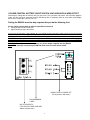
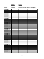
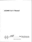
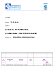
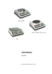
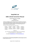
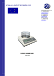
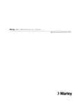
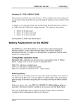
EM-900 User Manual
What’s Inside?
• EM-900 (with built-in rechargeable battery.)
• AC-2P power adaptor
• Cradle
What’s needed?
• 900 MHz spread spectrum transmitters
• Sensors (See list in Addendum A)
Important! Please Read This Page
Thank You for Purchasing The EM-900 from USP!
USP has made every effort to make The EM-900 the finest Monitoring System on the market today.
However, for your safety, please take the following precautions when using The EM-900:
•
The EM-900 should be tested regularly to ensure proper notification of your programmed transmitters
when activated by the Pendant transmitter or Wireless Accessories. This is your responsibility as the
user of the product.
•
Certain structures may block the transmitter signal. It is up to the user to test the transmitter within the
area of use to determine if “dead zones” exist, and where they are located.
•
For U.S. installations only: The EM-900 is required to comply with Part 15 of the FCC Rules and
regulations. As such, it has limited transmitter power and therefore limited range.
•
The EM-900 cannot respond to more than one transmitted signal at a time and maybe blocked by radio
signals that occur on or near their operating frequencies, regardless of code setting.
•
Changes or modifications to the device may void FCC compliance.
NOTE: This equipment has been tested and found to comply with the limits for a Class B digital device,
pursuant to Part 15 of the FCC Rules. These limits are designed to provide reasonable protection against
harmful interference in a residential or commercial installation. This equipment generates uses and can radiate
radio frequency energy and, if not installed and used in accordance with instructions, may cause harmful
interference to radio communications.
1
VOLUME CONTROL, BATTERY ON/OFF SWITCH, AND AUXILIARY ALARM OUTPUT
Removing the sliding door on the back will give you access to a 3-positiion slide switch, the transmitter program
cable, and the 3-terminal connector block for interfacing with an automatic dialer or some other (low-voltage)
device like a strobe light, external siren, etc.
Putting the EM-900 on active duty requires that you do the following first:
Set the (chime) sound switch to either of 2 positions as desired:
1. Center position for low sound level.
2. Upper position for high sound level.
Connect the AC-2P power supply adaptor to a live 120VAC outlet and plug the cable into the jack on the back of
the (optional) cradle or directly into the power jack located on top of the EM-900 if no cradle is used. While
charging, do not operate the EM-900 without the AC-2P adaptor. It may take up to 12 hours to fully charge the
battery. Once charged you should be able to operate the EM-900 for several hours before you will hear a series
of “beeps” indicating that the battery is running low, in which case you should immediately place the STATION
back in its cradle or re-connect the AC-2P.
CAUTION: To avoid permanent damage only use power adaptor supplied with the EM-900.
Note: When storing or transporting the EM-900, make sure to set the switch to OFF.
SOUND LEVEL & POWER OFF
(Three position slide switch)
PROGRAMMING
CABLE
RELAY CONTACTS
FOR LOW VOLTAGE AUXILIARY
APPLICATIONS ONLY
2
Installing the EM-900
Find a preferred location not closer than 12” from heavy metal objects or reflective surfaces
like mirrors. Placing the STATION too close to metal obstructions could impair its ability to
receive wireless signals from distant transmitters. Note: When not in the monitoring mode the
STATION will sound intermittent beeps to alert one to that condition.
Getting started......
Shortly after the EM-900 is powered up, the following message is displayed
EM-900
VERSION 1.16
PROGRAM Tx – program up to 40 STATIONS
You must first prepare the EM-900 to make it operate with your selection of transmitter/sensor combinations. Up
to 40(+) transmitters may be used with one EM-900, each to be assigned a unique code (pre-programmed at the
factory for ease of installation).
CAUTION:
Assigning the same code to more than 1 transmitter is generally not a good idea because:
(a) Transmitters with identical codes must also be programmed to activate by the same type of contact (either
normally open or normally closed)
(b) More importantly, the EM-900 would not be able to determine if a transmitter with a duplicate code has
become inactive or has been removed from the immediate area. Therefore, the concept of supervision will
be meaningless. Note: It takes only one active transmitter within the detection range to keep the EM-900
from sounding the MISSING Tx Alarm.
Next, you will be asked to select from one out of four choices
1 MON/NEW ENTRY
2 ON-OFF/VU LOG
Press ‘1’ to MONITOR all transmitter stations or PROGRAM a new transmitter station
Press ‘2’ to TURN STATION ON – OFF or VIEW STATION LOG
• (Press ‘1’ to program a new transmitter station)
Screen will then display
1 MONITOR
2 ADD TX/REVIEW
Press ‘1’ to MONITOR [only if STATION (S) 01 – 40 have been previously programmed]
Press ‘2’ to ADD TRANSMITTER or REVIEW STATION’S PROGRAM
• (Press ‘2’ to setup transmitter(s) with assigned code)
Screen will then display
1 ADD NEW TX
2 REVIEW STATION
Press ‘1’ to ADD a TRANSMITTER to a particular STATION
Press ‘2’ to REVIEW STATION (01 – 40) PROGRAM
• (Press ‘1’ to add a new transmitter code to a selective station)
Screen will then display
ENTER STATION #:
(01 - 40)
If a mistake is made in setting up your transmitters, refer to page 10, “CHANGING A TX CODE” for
corrections.
Enter a number between 01 and 40 to assign a station in which to store the code for a particular transmitter.
Note: If the assigned station is less than 2 digits, you must press star button after entry. You may assign stations
in any order. Once a code is stored, it remains in memory even if power is removed.
3
Example: Preparing a transmitter code and storing in an unused station.
In any of the program stages if an incorrect character has been entered, you can
simply press “R” to reenter information.
Enter 01 (for station 01).
Screen will then display
STATION: 01
If no previous code is stored in station 01, the display will show
Screen will then display
STATION NOT
PROGRAMMED!
Then
ENTER Tx CODE:
(0000 - 9999)
Transmitters are PRE-PROGRAMMED at the factor for ease of installation. Have transmitter code available
(located on side of transmitter housing) when setting up STATION. Keep a written record of codes stored.
Note: If the number entered is 4 digits or longer, the STATION will only accept the first 4 and automatically
advances to the next step. If the number is less than 4 digits, you must press * (asterisk) to continue.
Enter 1234 for this example
CODE: 1234
Then, after a short pause
CODE ENTERED!
(PRESS ‘M’)
•
(Press ‘M’ to store program)
By pressing the ‘M’ button you should hear 2 short ‘beeps’ simultaneous with the front light flashing, indicating
that programming the transmitter is successful and complete. The EM-900 keeps a profile of all the codes
programmed and can therefore determine while in the MONITORING mode which transmitter is tripped.
Followed by
ENTER LOC OF TX:
(0000 - 9999)
Enter a LOCATION assigning a reference number of up to 4 digits
Enter 01 (or any number that helps you recall where this transmitter is physically located) then press *.
Note: Pressing * without entering a location number will leave the number field blank.
LOC: 01
Then
4
NAME: MAX 11 CHAR
THEN PRESS (*)
Enter the name of a location or any other description of less than 11 alpha characters
At this stage you’re asked to enter alphabetic characters via the EM-900 keypad. Looking at the keypad, you’ll
notice the additional alphabetic letters printed on numeric keys 2 through 9. To enter a letter, press the
corresponding key in quick succession in accordance with the placement of the character.
For example: for the letter “C” press the “2” key three times in a row. Use the “1” key for a space. In so doing
you can construct a name in upper case style only not exceeding 11 characters. Note: By simply pressing the *
key, the name field will be left blank.
Note:
Pressing the “0” key once will give you the exclamation (!) character.
Pressing the “0” key twice will give you the quotation (“) character.
Pressing the “0” key 3 times will give you the pound (#) character.
Using this sequential method try entering the name “JOE SMITH”.
In any of the program stages if an incorrect character has been entered, you can
simply press “R” to reenter information.
When you are finished with this process (*), the screen will then display…
01: JOE SMITH
Then you are given a choice of
1 ACCEPT
2 START OVER
Press ‘1’ to ACCEPT STATION PROGRAM
Press ‘2’ to START OVER from scratch
• (Press ‘1’ if program was correctly entered)
Screen will then display
1 MON/NEW ENTRY
2 ON-OFF/VU LOG
REVIEW STATION’S PROGRAM
1 MON/NEW ENTRY
2 ON-OFF/VU LOG
Press ‘1’ to MONITOR or ENTER NEW PROGRAM
Press ‘2’ to TURN STATION ON – OFF or VIEW STATION LOG
• (Press ‘1’ to verify programmed entry)
Screen will then display
1 MONITOR
2 ADD TX/REVIEW
Press ‘1’ to MONITOR (only if STATION (S) 01 – 40 has been previously programmed)
Press ‘2’ to ADD TRANSMITTER or REVIEW STATION’S PROGRAM
• (Press ‘2’ to review program)
Screen will then display
1 ADD NEW TX
2 REVIEW STATION
Press ‘1’ to ADD a TRANSMITTER to a particular STATION
Press ‘2’ to REVIEW STATION (01 – 40) PROGRAM
• (Press ‘2’ to verify a particular station setup)
5
ENTER STATION #:
(01 - 40)
Enter 01 (for station 01).
Note: for a single digit station be sure to add a 0 before the number; (i.e.: 08, 09)
Transmitter code will be displayed
1234
Followed by Location and Name
01: JOE SMITH
Followed by station status
STATION ON
MONITOR – Uninterrupted surveillance of alarm sensors
1 MON/NEW ENTRY
2 ON-OFF/VU LOG
Press ‘1’ to MONITOR or ENTER NEW PROGRAM
Press ‘2’ to TURN STATION ON – OFF or VIEW STATION LOG
• (Press ‘1’ to begin monitoring process)
Screen will then display
1 MONITOR
2 ADD TX/REVIEW
Press ‘1’ to MONITOR (only if STATION (S) 01 – 40 have been previously programmed)
Press ‘2’ to ADD TRANSMITTER or REVIEW STATION’S PROGRAM
• (Press ‘1’ to have uninterrupted surveillance of alarm sensors)
Screen will then display
MONITORING!
(‘M’ TO CANCEL)
After properly programming the wireless grid of remotely located transmitters, the EM-900 is now ready to
perform its duty of monitoring the following conditions:
• ALARM caused by tripping a remote sensor connected to its transmitter (only if ENABLED).
• Tx MISSING when a transmitter stops operating for more than 30 minutes in a row or is completely removed
from the area under surveillance (only if ENABLED).
• LOW BATTERY of transmitter STATION when voltage drops below 2.5V (only if ENABLED).
Any of the following messages may appear during the monitoring phase.
ALARM!
Or
Tx MISSING!
Or
LOW Tx BATTERY!
6
What you should do when the alarm is activated?
When in alarm, the EM-900 flashes a red light while sounding a two-tone chime, (either high or low volume), and
continues to do so until the “M” key is pressed. In case of a true ALARM or Tx MISSING (let’s assume Joe
Smith tripped his sensor or left the area for more than 30 minutes) after pressing the “M” key, you will see
01: JOE SMITH
Pressing “M” key once more stops the alarm sound and light flashing.
If LOW BATTERY, after pressing the “M” key, you will see
STATION:01
Then pressing the ‘M’ key again you will see
STOP MONITORING?
YES (1) NO (2)
Notes:
1. The EM-900 is capable of “stacking” up to 10 alarms in a row. This important feature prevents loss of
information before the first alarm is being looked in by pressing the “M” key once. Thereafter, pressing “M”
again will cause additional alarms (if any) to be displayed in sequence of their occurrence.
2. The low battery alarm will be issued every 18 hours until the battery is replaced. Please do so as soon as
possible to prevent the transmitter in question from becoming totally inactive in the days or weeks ahead.
STATION ON/OFF
1 MON/NEW ENTRY
2 ON-OFF/VU LOG
Press ‘1’ to MONITOR or ENTER NEW PROGRAM
Press ‘2’ to TURN STATION ON – OFF or VIEW STATION LOG
• (Press ‘2’ to TURN STATION ON – OFF or VIEW STATION LOG)
This section is used to either turn STATION ON or STATION OFF. When disabled by turning ‘STATION’ off, all
alarms from that particular transmitter will be ignored. For example, it may be necessary to occasionally turn that
particular station off, disable a sensor from sending an alarm during maintenance or for any other reason.
ENTER STATION #:
(01 - 40)
Enter 01 (for station 01).
STATION: 01
Screen will then display
1 STATION ON - OFF
2 VIEW DATA LOG
Press ‘1’ to CHANGE STAION CONFIGURATION from ON to OFF or OFF to ON
Press ‘2’ to VIEW STATION LOG
• (Press ‘1’ to verify STATION setup)
7
STATION ON
01: JOE SMITH
Then you are given a choice of
TURN OFF?
YES (1) NO (2)
Press ‘1’ to TURN STATION OFF
Press ‘2’ to leave STATION ON
• (Press ‘2’ No, to leave STATION ON)
VIEW DATA LOG – Examining ALARM log, Tx MISSING log, and MISSED codes
This data-logging feature allows you to evaluate important information collected over time by storing:
• The total number of times each transmitter has been tripped. The maximum count is 99. Beyond 99 the
display will show “>”. You may reset the count to 0 at any time.
• The total number of times a transmitter is found to be missing when the receiver fails to record 30 check-in
codes (in a row) sent at 1 minute intervals, causing the Tx MISSING counter to be incremented by one for
each such occurrence. The maximum count is 99, which may be reset at any time.
• The highest number of missed check-in codes in a row of less than 30 recorded during the monitoring
process. This is an important measure by which you can judge how reliable the wireless link is for individual
transmitter Stations. Remember, a Tx MISSING alarm will be given if there are 30 missing check-in codes in
a row. The maximum count is 30. Beyond 30 the display will show “>”. You may reset the count to 0 at any
time. As a rule of thumb, the largest number of missed codes for each transmitter should not exceed 15
over a 24-hour period. If it does, you may have to reduce the distance or change location of that particular
transmitter to minimize the risk of false alarming.
Note: Data logging only applies to receiving channels that are enabled.
1 MON/NEW ENTRY
2 ON-OFF/VU LOG
Press ‘1’ to MONITOR or ENTER NEW PROGRAM
Press ‘2’ to TURN STATION ON – OFF or VIEW STATION LOG
• (Press ‘2’ to TURN STATION ON – OFF or VIEW STATION LOG)
ENTER STATION #:
(01 - 40)
Enter 01 (for station 01).
STATION: 01
Screen will then display
1 STATION ON - OFF
2 VIEW DATA LOG
Press ‘1’ to CHANGE STAION CONFIGURATION from ON to OFF or OFF to ON
Press ‘2’ to VIEW STATION LOG
• (Press ‘2’ to VIEW DATA LOG information)
Then, in sequence you’ll see the following messages
ALARM LOG:
8
0
MISSING TX LOG:
0
MISSED CODES:
If there were 3 missed check-in codes in a row the display shows
3
RESET TO 0?
YES (1) NO (2)
YES if you want the count to be reset to 0, otherwise it will remain in memory.
Changing a transmitter code
If a stored code needs to be changed, follow these steps.
First go to initial setup prompt by scrolling through display or by simply turning power switch off and back on with
adaptor unplug from unit. Identify the memory location of the transmitter code you wish to change.
1 MON/NEW ENTRY
2 ON-OFF/VU LOG
Press ‘1’ to MONITOR or ENTER NEW PROGRAM
Press ‘2’ to TURN STATION ON – OFF or VIEW STATION LOG
• (Press ‘1’ to begin programming)
Screen will then display
1 MONITOR
2 ADD TX/REVIEW
Press ‘1’ to MONITOR (only if STATION (S) 01 – 40 have been previously programmed)
Press ‘2’ to ADD TRANSMITTER or REVIEW STATION’S PROGRAM
• (Press ‘2’ to setup transmitter(s) with assigned code)
Screen will then display
1 ADD NEW TX
2 REVIEW STATION
Press ‘1’ to ADD a TRANSMITTER to a particular STATION
Press ‘2’ to REVIEW STATION (01 – 40) PROGRAM
• (Press ‘1’ to add a new (or change) transmitter code to selective station)
ENTER STATION #:
THEN (*)
Enter 01 (for station 01)
Go to memory location 01 which should contain code 1234 from previous example.
9
Enter 01
STATION:01
Shortly thereafter the previously stored code is displayed
1234
ENTER Tx CODE:
THEN (*)
To continue with the setup, refer to the “LOC” setup on the bottom of page 4.
You may now enter the new code, and re-program the designated transmitter.
OR
By simply pressing * you will be asked
WIPE RECORD?
YES (1) NO (2)
If YES, the previously stored record will be wiped and that location is pre-empted for future use.
Finally
DONE?
YES (1) NO (2)
If NO you may continue programming additional transmitters (or changing codes) until memory is full or if YES
you will exit the PROGRAM Tx mode and go to CONFIGURE.
Important: Under normal operating conditions the STATION should remain in its
recharging cradle to keep the battery at full capacity. This will allow portable
operation when needed for up to four hours.
YES to program the transmitter via program cable, resulting in the message
CONNECT Tx CABLE
THEN...
Familiarize yourself with the procedure of connecting the 3-wire program cable (tucked inside the back
compartment of the EM-900) to a transmitter module. See pictures on the last page. First, remove the
transmitter cover and look at the illustrations for the different models that can be used with the EM-900. After
you have correctly attached the cable, momentarily press the reset button shown in the pictures. You should
hear 2 short ‘beeps’ simultaneous with the front light flashing, indicating that programming the transmitter is
successful and complete. The EM-900 keeps a profile of all the codes programmed and can therefore determine
while in the MONITORING mode which transmitter is tripped.
CAUTION: If you decide to press the ‘M’ TO CANCEL option instead of pushing the Tx reset button, even with
the programming cable attached, the new code will not be stored inside the transmitter. Therefore, the EM-900
will not recognize any alarms from that particular transmitter.
PRESS Tx RESET
OR ‘M’ TO CANCEL
10
6. PROGRAMMING TRANSMITTER STATIONS VIA THE 3-CONDUCTOR CABLE
Figure 1 - Typical cable connection to a universal transmitter with cover off.
Figure 2 – Close-up view of above transmitter hookup.
The 2-terminal connector on the right may be used with any
dry contact sensor type so long as you correctly program the
transmitter for either:
a. Type 1 (N.O.) when the contact closes during alarm. This
may be the case using a pressure mat to send the alarm
when stepped on.
b. Type 2 (N.C.) when the contact opens during alarm. In
this application the same pressure mat may be used to
send an alarm when pressure is removed.
RESET BUTTON
Figure 3 – Typical pendant transmitter (cover removed).
Pendant transmitters like the on the right are considered Sensor Type
1 (N.O.) devices and therefore you must enter that option only when
programming its digital code as described in example 1. After
programming, make sure to replace the watertight cover by uniformly
tightening the 3 screws on the back. Do not apply excessive torque!
RESET BUTTON
11
ALL ECP wireless receivers have the capability to supervise all ECP universal transmitters. They
also have the ability to pickup lo battery-warning signals from these transmitters. Every 60
seconds the transmitter sends andI’m here’ signal to the receiver. If not sensed by the receiver in
a thirty-minute period the alarm will sound. This means protection from low power, non-working
transmitters or transmitters removed from the facility.
CC-900-Care Caller-Enunciator with Pendant Transmitter. Wristband, necklace and belt clip.
Fall Alert Complete Systems - 900 MHZ Long Range - includes accessories
FA-900- 1
Bed/Rail System with LT-900 transmitter, Enunciator, 1” x 30” Sensor Strip Pad, AC
Adapter
FA-900- 2
Bed/Rail System with LT-900 transmitter, Enunciator, 2” x 30” Sensor Strip Pad, AC
Adapter
FA-900- 3
Wheelchair-Seat System with LT-900 transmitter, Enunciator, 9”x16” Sensor Pad, AC
Adapter
FA-900- 4
Bed System with LT-900 transmitter, Enunciator, 14” x 24” Sensor Pad, AC Adapter
FA-900- 5
Bed System with LT-900 transmitter, Enunciator, 18” x 24” Sensor Pad, AC Adapter
FA-900- 6
Floor System with LT-900 transmitter, Enunciator, 24” x 30” Sensor Pad, AC Adapter
FA-900- 7
Floor System with LT-900 transmitter, Enunciator, 24” x 36” Sensor Pad, AC Adapter
Addendum A
List of Accessories:
E-MD
LR-900
LP-900
900S-DW
LT-900
CE-900
Wireless Motion Detector
Intelligent Repeater for Extending Range
Pendant transmitter
Wireless Door Window transmitter
Wireless Transmitter w/ RJ22 connection
Wireless Receiver/Alarm Strobe
Sensor Pads
P-1-22
P-2-22
P-3-22
P-4-22
P-5-22
P-8-22
P-9-22
2x01 Bed and Rail Sensor Strip with 4 foot lead & RJ22 Plug
14x24 Bed Sensor Pad with 4 foot lead & RJ22 Plug
18x24 Bed Sensor Pad with 4 foot lead & RJ22 Plug
24x01 Bed Sensor Pad with 4 foot lead & RJ22 Plug
9x16 Chair Sensor Pad with 4 foot lead & RJ22 Plug
24x36 Floor Sensor Pad with 4 foot lead & RJ22 Plug
24x60 Floor Sensor Pad with 4 foot lead & RJ22 Plug
Automatic Voice Dialers
AD2000- Hard-wired, phone or page 8 numbers. Leave a special message. (Other models
available.)
United Security Products, Inc.
13250 Gregg Street Suite B
Poway, CA 92064 (800) 227-1592
(858) 597-6677
Fax: (858) 455-0036
Last update: 09/09/03
12
E-Mail:
[email protected]
EM-900
Planner
Station
Location
Reference Tx Code Name or Description
STATION# 1
STATION# 2
STATION# 3
STATION# 4
STATION# 5
STATION# 6
STATION# 7
STATION# 8
STATION# 9
STATION# 10
STATION# 11
STATION# 12
STATION# 13
STATION# 14
STATION# 15
STATION# 16
STATION# 17
STATION# 18
STATION# 19
STATION# 20
STATION# 21
STATION# 22
STATION# 23
STATION# 24
STATION# 25
STATION# 26
STATION# 27
STATION# 28
STATION# 29
STATION# 30
STATION# 01
STATION# 32
STATION# 33
STATION# 34
STATION# 35
STATION# 36
STATION# 37
STATION# 38
STATION# 39
STATION# 40
01
1234
JOE SMITH
13
Station
EM-900
Planner
Location
Reference Tx Code Name or Description
STATION# 1
STATION# 2
STATION# 3
STATION# 4
STATION# 5
STATION# 6
STATION# 7
STATION# 8
STATION# 9
STATION# 10
STATION# 11
STATION# 12
STATION# 13
STATION# 14
STATION# 15
STATION# 16
STATION# 17
STATION# 18
STATION# 19
STATION# 20
STATION# 21
STATION# 22
STATION# 23
STATION# 24
STATION# 25
STATION# 26
STATION# 27
STATION# 28
STATION# 29
STATION# 30
STATION# 01
STATION# 32
STATION# 33
STATION# 34
STATION# 35
STATION# 36
STATION# 37
STATION# 38
STATION# 39
STATION# 40
14
15
16