1
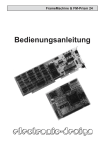
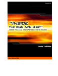
http://www.3jtech.com.tw
CAMit I
Camera with built in Modem
User’s Manual
CAMit I AP revision: 3.3
CAMit I Setup revision: 2.0.1
Manual revision: 2.0
Date: February 27, 2002
http://www.3jtech.com.tw
Congratulations
You just acquired a fine product from 3JTech.
We carefully manufactured our products for you. Each unit is assembled within our own
premises with the highest standard of quality.
Our personnel are pleased to provide you with the best-engineered technology.
If, for whatever reason, you are not satisfied and the product is not up to the specifications
posted, our products are fully guaranteed.
You are invited to visit our website, http://www.3jtech.com, in order to get the latest news
about our products as well as free version of the latest software from 3JTech Co. Ltd.
http://www.3jtech.com.tw
Table of Content:
Table of Content:..................................................................................................................3
1. Product Overview: ...........................................................................................................5
1.1 Introduction .............................................................................................................5
1.2 Features .................................................................................................................5
1.3 Package Content ....................................................................................................5
2. Physical Description.........................................................................................................6
2.1 The Front Panel ......................................................................................................6
Lens ...............................................................................................................6
2.2 The Back Panel ......................................................................................................7
RS232 Serial Connector.................................................................................7
Phone Line Connector....................................................................................7
Power Supply Connector................................................................................7
Serial Number / Firmware version ..................................................................7
2.3 The Side Panel .......................................................................................................8
Power indicator...............................................................................................8
Status indicator...............................................................................................8
2.4 Power Supply Adaptor ............................................................................................9
Power Point Adaptor.......................................................................................9
RJ 22 Camera Point .......................................................................................9
Trigger In / Out Connector..............................................................................9
Trigger Out .....................................................................................................9
Trigger In ........................................................................................................9
Ground ...........................................................................................................9
3. Assembling Camera.......................................................................................................10
3.1 Mounting Methods ................................................................................................10
3.2 Outdoor Housings.................................................................................................10
4. Quick Setup / Installing Your Camera Software ............................................................. 11
4.1 Installing Software ................................................................................................ 11
4.2 Modem..................................................................................................................13
5 Application Software provided.........................................................................................14
5.1 CAMit I Setup........................................................................................................15
5.1.1 Setting parameters .....................................................................................15
5.1.2 Registering the parameters ........................................................................16
5.2 Using the CAMit I: CAMit I AP...............................................................................17
5.2.1 Setting your CAMit I sites ...........................................................................17
Option Menu: .......................................................................................................18
Utility Menu..........................................................................................................19
http://www.3jtech.com.tw
Help Menu ...........................................................................................................19
Camera Menu......................................................................................................20
Calling a site ...............................................................................................................21
6 Motion Detection.............................................................................................................22
7 How do I use the Trigger In /Out? ...................................................................................22
8 Camera Image Size ........................................................................................................24
8.1 Change Image Size ..............................................................................................24
8.2 Change Screen Size.............................................................................................24
9 Record / Play Images......................................................................................................25
9.1 How do I record images?...............................................................................25
9.2 How do I play recorded images? ...................................................................26
10 Frequently Asked Questions: ........................................................................................27
Does my computer at the remote site need to be turned on upon trigger?...27
Will the images be recorded automatically upon trigger? .............................27
Can I view the same site from different locations? .......................................27
Can I view same site simultaneously from 2 locations?................................27
Why won’t my modem in the camera recognize the dial tone?.....................27
Why won’t my external trigger input work? ...................................................27
Will my PC alert me upon trigger?................................................................28
What should I do if I forget my password?....................................................28
11. Specifications ...............................................................................................................29
http://www.3jtech.com.tw
1. Product Overview:
1.1 Introduction
CAMit I is a color camera with a built-in modem. This camera is a complete system by itself,
working as a stand-alone viewing center.
It can be connected at any regular residential telephone line, or analog PBX extension line,
to transmit live images via phone line. You can dial in the CAMit I from any remote location
using a computer and modem to monitor in real time and record images.
The CAMit I can also be triggered by its built-in motion detection, normal close to open or
other external TTL level signal devices. Upon trigger, CAMit I will automatically dial out and
send images to a remote pre-set computer for recording.
1.2 Features
Low cost, DIY remote security camera
NO computer needed at monitored site
Point to point, modem to modem, real time remote monitoring
Sensitivity adjustable motion detection, for security purposes
Trigger In connector for connecting external sensor for monitoring and security
purposes
Trigger Out connector for connecting external alarm for monitoring and security
purposes
Record images onto hard drive of computer, Jpeg format available
Firmware upgradeable and user’s parameters programmable memory
Password protection
Small size and low power consumption
Automatic gamma correction
Non aging CMOS image capture device
1.3 Package Content
1) 1 CAMit I camera
2) 1 CD with software (CAMit I Setup & CAMit I AP) and user’s manual
http://www.3jtech.com.tw
3) 1 RJ11 telephone line cord
4) 1 (120 V, 60 Hz) Power adaptor with Trigger In/Out connectors
5) 1 DB9 (RS232) serial connector cable for setup
2. Physical Description
The following information contains the physical description of CAMit series camera. This
includes the functions and the locations of each connector and indicator. The information
provides useful reference when installing the product. Please familiarize yourself with
CAMit cameras.
2.1 The Front Panel
Lens
Lens
CAMit I box includes a standard 120° wide angle lens fix to the camera. For custom user,
other types of lens are also available upon request. Please note that different price may
occur with different lenses.
http://www.3jtech.com.tw
2.2 The Back Panel
RS232 Serial Connector
Serial Number
Firmware version
Phone Line
Connector
RJ22 Power
Connector
RS232 Serial Connector
This serial connector provides links between the computer and the camera via RS232. This
connector is used for the computer to configure the camera for the first time.
Phone Line Connector
CAMit I is designed for connection via phone lines and modems, please plug the phone line
here.
Power Supply Connector
CAMit adopts unique RJ22 cable for power supply. The special featured RJ22 cable
includes Input / Output (I/O) function. Simply connect the Input / Output cable to desire
address and no hardware jumper fixing on camera is required.
Serial Number / Firmware version
The label sticker includes the serial number and the Firmware version of the camera.
Note. If you have updated the camera firmware version, the firmware version information
may no longer be valid.
http://www.3jtech.com.tw
2.3 The Side Panel
Power Indicator
Status Indicator
Power indicator
The power indicator normally lit when power is applied. If the LED is not lit or flashing, then
there could be a problem with the power supply.
Status indicator
Normally the status indicator blinks every second. When motion detection is enabled the
LED will blink 4 times rapidly. With the LED blinking constantly with high frequency or not lit
at all, there could be problem with the camera.
http://www.3jtech.com.tw
2.4 Power Supply Adaptor
Trigger In
Trigger In/Out
Connector
Ground
Trigger Out
RJ22 Camera Point
Power Point Adaptor
Power Point Adaptor
Plug the power point to your local power point. The specifications for the power adaptor are
as follows:
Input: 100 – 240Vac ~ 0.3A 50/60Hz
Output: 5.0Vdc / 2.0A
RJ 22 Camera Point
Plug this end to the camera’s RJ22 slot.
Trigger In / Out Connector
The Trigger In/Out connector cable is connected to the RJ22 AC power adaptor.
Trigger Out
The Red cable is for Trigger Out and it needs to be connected to TTL level (0 – 5 V)
external devices.
Trigger In
The White cable is for Trigger In and it also required to be connected to TTL level (0 – 5 V)
external devices.
Ground
The Ground cable is the black and can be found both on Trigger In and Trigger Out.
http://www.3jtech.com.tw
3. Assembling Camera
The information provided in this section will assist you in assembling and install the product
correctly. It is recommended to configure the camera before positioning the camera.
3.1 Mounting Methods
CAMit I comes with a desktop mount upon purchase. To position the camera, fasten the
camera with screws in the holes at the base of the mount. The default
mount configuration is the desktop mount.
In case of ceiling mount, remove the screws attaching the mount to the
camera and re-attach the mount to the spare hole on the top of the
camera.
Wall mounting leg is optional accessory upon request with additional charge. Please
contact your local dealer for more information.
3.2 Outdoor Housings
CAMit I cameras are not designed to be outdoor camera. Due to the unexpected exterior
environment, extra housing is required if you wish to install CAMit cameras outdoors.
http://www.3jtech.com.tw
4. Quick Setup / Installing Your Camera Software
This section will teach you how to setup the camera step by step, including the installation
of application software and using the software to configure the camera.
4.1 Installing Software
1.
Place the Application CD into your CD-Rom drive.
2.
When the Install window show up, select “Setup CAMit I AP” If the window does not
load automatically, please go to my computers and double click on the CD-Rom drive
with installation CD or run the setup.exe file under CAMit I directory.
http://www.3jtech.com.tw
3.
After selecting “Install CAMit I” the Install Shield Wizard window should appear and
take you through installing. Please follow the instructions and press Next.
4.
5.
The window will then ask you for your user information. Please enter the user
information accordingly.
Choose Destination Location – If you wish to change the destination folder for CAMit I
software, please press browse and select your desired folder else press Next.
6.
Start Copying Files – Please click Next to continue or Back to go back to Choose
Destination Location.
7.
Please wait while the program is installing.
8.
Click Finish when installation is complete.
http://www.3jtech.com.tw
4.2 Modem
Before proceeding with a remote CAMit I session, your PC should have a modem installed.
Please, refer to your operating system to install and configure your modem.
As a reference, usual modem parameters are to be used with CAMit I. Most common ones
are the following:
8 bits, no parity, 1 stop bit
Hardware Flow Control, Clear to Send (CTS)
Carrier Detect: ON
Normal DTR Operations
Auto Answer ON if you wish to received a call dialed by a triggered CAMit-I.
(Please refer to your modem user manual for more information on installing the
modem.)
http://www.3jtech.com.tw
5 Application Software provided
Before getting started with the CAMit I, you should have already installed the software
programs (CAMit I Setup & CAMit I AP) and downloaded this user’s manual from the CD
provided in the package.
The CAMit I Setup is used to setup the parameters of the camera. It needs to be connected
to the camera using a PC via a serial port. To do so, a DB9 RS232 serial cable is provided
from the package.
The CAMit I AP is the application software to communicate with the CAMit I remotely.
Please read this user’s manual thoroughly to understand the functions and capabilities of
the CAMit I camera.
http://www.3jtech.com.tw
5.1 CAMit I Setup
Prior to start using CAMit I, certain parameters of the camera need to be set.
First, please connect your CAMit I to a PC using the DB9 cable included and then run the
CAMit I Setup program installed from the CD included in the package. You may also
download the latest version that matches your CAMit I model from the
www.3jtech.com/Downloads.htm web site.
Start the CAMit I Setup application. After selecting the correct serial port and connecting the
PC to the CAMit I, you can begin setting the parameters of CAMit I.
5.1.1 Setting parameters
Use the main menu to set up the
parameters to your needs. Below is
an explanation of the terms used
for the settings.
Utility
Update Firmware:
Update the Firmware of your CAMit I here.
http://www.3jtech.com.tw
Country:
Please select the country that you are in or one with similar phone line system. If you do not
know, please contact your local telephone company for more information.
Phone Number:
Please enter the phone number of the computer PC that will be receiving the triggered
image files from the CAMit I.
Extension:
Please check and enter the extension number of the computer PC that will be receiving the
triggered images files. If there is no extension number, please leave it blank.
Delay Time (sec):
Please enter the delay time (unit = seconds) after dialing the phone number and before
dialing the extension number, if any is used.
Output duration (sec):
If you have a Trigger Out device connected, you can set the time duration of the Trigger Out
device here.
Time Lag To Start Motion Detection (sec): Upon enabling the Motion Detection, you can
set the time lag for it to start. The time lag is necessary for you to leave the scene without
false triggering the camera.
Change New Password:
Set a password to view the CAMit I site. A password is not required to use the CAMit I and
the default value is none.
5.1.2 Registering the parameters
When you are finished setting the camera’s parameters, you must save the new setting to
the camera, else you the new settings will not be saved. To do so, simply click the save
button after all parameters are set. You can then, disconnect the camera with the PC and
ready to be postioned.
Fix your camera at the site that you wish the camera to be. When the CAMit is secured,
simply connect it to a telephone line and provide power. You are now ready to use the
CAMit I camera. Please refer to the next section.
http://www.3jtech.com.tw
5.2 Using the CAMit I: CAMit I AP
After the parameters are set and the CAMit I is connected to
a phone line, from a remote PC, you can run the CAMit I AP
and dial in with a modem.
When you first load the application, the system will demand
you to select the modem you will be using to dial to your
camera. You must have a modem selected in order to dial.
5.2.1 Setting your CAMit I sites
The following information will help you to understand the basic functions of the CAMit I AP
to set up your site or different sites:
After the modem is selected, the main window will appear.
Here is the main menu.
The modem
selected
http://www.3jtech.com.tw
File
Exit:
Exits the CAMit I AP application.
Option Menu:
Option
Site Setup:
Sets the dial parameters of the computer PC.
When you check the Advance Setup, a set of
new menu would show up for you to do
advance setup.
Camera Site Name: Name of the camera
site.
Camera Phone Number: The phone
number to access the CAMit I. This is the
phone number that the PC will be dialing if you wish to open a session with a specific
CAMit I camera.
Number to Dial to Reach Outside Line: The number the computer PC needs to dial
to access an outside line. If none, please leave blank.
Outside Delay Time: The delay time (unit = seconds) after dialing the outside line and
before dialing the phone number.
Extension Number at Camera Site: The extension number of the CAMit I site, if any,
should be entered here.
Extension Number Delay Time: The delay time (unit = seconds) after dialing the
phone number and before dialing the extension number, if any.
Time Interval between redial (sec): The time duration (unit = seconds) between each
redial.
Redial Number: The number of attempts the computer PC will try to dial the CAMit I
site if connection is not established the first time.
Number of Rings before Answering upon Trigger: The number of rings the
computer PC will wait before answering when CAMit I calls back after triggered.
http://www.3jtech.com.tw
Option
Modem Select:
Select your modem. You can choose a different modem
for dialing out from your PC to your CAMit I. The modem
needs to be installed prior before selection can be made.
(Please your modem user manual for more information on installing
the modem.)
Option
Modem Configuration:
You can configure your chosen modem here. Usually, the parameters shown are adequate
to communicate with CAMit I and that value will resurface whenever you reboot the
computer session. However, you may select different values for a specific session.
Utility Menu
Utility
Set Recording Time:
Set the recording time duration of the
received images.
Utility
Set Recorded Image Files Directory:
Set the file location for where the received images will be saved.
Utility
Play Recorded Images:
Launches the Image File Player to be able to play stored image files. You may save a still
picture in Jpeg file format (JPG) by clicking onto the JPG icon.
Utility
PC Alarm Settings:
You can set the Alarm sound and duration upon a CAMit I call is received at the PC. The
sound files need to be a wave file, and the duration unit is in seconds.
Help Menu
Help
About:
Shows the CAMit I AP revision number.
http://www.3jtech.com.tw
Camera Menu
Camera
CAMit I).
Setting: (only works when connection is established between computer PC and
Password: Here you may set the
password for viewing your camera.
Please enter the desired password to the
password and confirm password box
accordingly
Number of Rings Before Answer: Here
you can set the number of rings before
the camera would pick up when you dial
with your PC.
No. to Call upon Trigger: Here is where you can set the number which your camera
will dial when it has been triggered.
Camera
Trigger Status: (only works when
connection is established between computer PC
and CAMit I).
Motion Detection: Check to enable or
Disables the Motion Detection
Sensitivity Level: Check the desired
sensitivity level. Choose between High,
Medium or Low.
Trigger In: Click to enable / disable Trigger
In function.
Time Duration of Trigger Output upon
Trigger: Here you can set the trigger output
duration when the camera is triggered. For example, the time duration that the camera
trigger the light to turn on.
Manually Trigger Out: Here you can manually trigger out to external devices such as
lights or alarms.
Camera
Image Size: (only works when
connection is established between computer
PC and CAMit I) Set the sensitivity level of the
Motion Detection function. You can set the
image size to large, medium or small by selecting from the menu.
http://www.3jtech.com.tw
Camera
Display Size: (only works when
connection is established between computer
PC and CAMit I). Here you can choose
between normal double the screen size by
enlarge the image via software.
Calling a site
From the main menu, select DIAL and
proceed with the site choose. (Note: The CAMit I phone number will not appear under the Camera Site
Name window.) Click OK the dialing process will take place. If a password is being used, a
screen will pop up to request the input. Whenever the picture comes in, you are in real time
with the CAMit I.
Click on Advance Setup to set
the dial parameters of the PC
and CAMit I.
Number to Dial to Reach
an Outside Line: The
number the computer PC needs to be dial to access an outside line. If none, please
leave blank.
Outside Line Delay Time: The delay time (unit = seconds) after dialing the outside
line and before dialing the phone number.
Extension Number at Camera Site: The extension number of the CAMit I site, if any,
should be entered here.
Extension Delay Time: The delay time (unit = seconds) after dialing the phone
number and before dialing the extension number.
Time Interval between Redial (sec): The time duration (unit = seconds) between
each redial.
Redial Number: The number of attempts the computer PC will try to dial if connection
is not established the first time.
Number of Ring Before Answering Upon Trigger: The number of rings the
computer PC will wait before answering when CAMit I calls back after triggered.
Hang Up:
Exits an established connection between a
PC and CAMit I.
http://www.3jtech.com.tw
6 Motion Detection
The Motion Detection function is a very valued function of the camera. It allows users to use
the camera for security purposes, as the function will send image files to a pre-set computer
upon motion detection. The files will also automatically be recorded to the hard drive of the
computer for future reference. To use the Motion Detection function, users need to:
•
•
Run the CAMit I AP software and dial into the camera you wish to set.
After connection is established, under Camera
Setup Trigger Mode, enable the
Motion Detection by selecting it. A check to the left of Motion Detection means that
Motion Detection is enabled.
•
Once Motion Detection is enabled, you also need to set the phone number for which
you want you CAMit I to dial into. To set the phone number, go under Camera
Settings.
Note:
•
There are also two parameters you can set for the Motion Detection:
o Set Sensitivity: This allows you to set the sensitivity of the Motion Detection.
o Set Time Lag To Start Motion Detection: This allows you to set the time lag
to start motion detection. Default value is 30 seconds.
•
The computer that will be receiving the image files needs to be turned on and the
CAMit I AP software needs to be running in order to receive files of triggered images.
•
The triggered image files will be saved automatically in the directory that can be set
under Utility
Set Recorded Image Files Directory.
•
To verify the activation of Motion Detection, a green light on the side of the CAMit I
should be blinking.
•
Default status of Motion Detection is OFF.
7 How do I use the Trigger In /Out?
The Trigger In/Out connector cable is connected to the RJ22 AC power adaptor. The Black
cables are Ground, the Red cable is for Trigger Out, and the White cable is for Trigger In.
Trigger Out is for connecting external alarms, and Trigger In is for connecting external
sensors. The Trigger In/Out cables need to be connected to TTL level (0 – 5 V) devices and
are normal close (short /connected to GND). Open or High will trigger the CAMit I (Trigger
In) or TTL level device (Trigger Out). To use the Trigger In/Out, you will need to enable the
Trigger In/Out function from the software AP (CAMit I AP). To do so:
http://www.3jtech.com.tw
•
•
First, you need to dial into the site and establish connection.
Then, under Camera
Setup Trigger Mode, enable the function you desire by
selecting it. A check to the left means that the function is enabled.
Note:
•
You can also set the time duration of Trigger Out under Camera
Status.
•
For Trigger In, if the sensor connected is triggered, then it will activate the
camera to start send images to the pre-set computer.
Trigger
http://www.3jtech.com.tw
8 Camera Image Size
You will only be able to change the camera image size when valid connection is present.
With our CAMit I AP software, you will be able to choose between the total of 6 images
sizes for viewing. CAMit I camera has 3 different hardware resolutions to chose when
browsing; Large size (320 x 240pixels), Medium Size (160 x 120pixels) and Small Size (120
x 96pixels). Different image resolution will affect the smoothness and the file size when
recorded.
Not only CAMit I AP provides hardware resolution but further more provide the user with
software blown up screen image sizes. You can choose between seeing the images with its
normal size or double the image size. The blow up image is digitally done within your
system; therefore it will not affect the smoothness or the stored file size.
Note. Software enlarged images can be blurry and not as clear as the hardware images
due to the digital zooming process.
8.1 Change Image Size
You can also from File menu’s Camera
Image Size and chose from the list.
Supervisor Passwords may be required when
you are tempting to change the image size.
This is because the information regarding to
image size is embedded in the camera. Thus
changing it requires authorization from the
administrator.
8.2 Change Screen Size
To choose the screen size simply click on the
shortcut buttons on top of the image screen or
you can select from File menu’s Camera
Screen Size and chose from the list.
http://www.3jtech.com.tw
9 Record / Play Images
This section will show you how to record and play image files.
9.1 How do I record images?
Simply click on the Record button when
viewing a particular site and image files
will begin recording to the hard drive of the
computer. The images will keep recording
until Record is un-clicked.
under Utility
The directory for which the
image files are recorded to
will be saved in the
directory that can be set
Set Recorded Image Files Directory.
http://www.3jtech.com.tw
9.2 How do I play recorded images?
Simply go to Utility
Play Recorded Image and
select the file you wish to play. You may stop a
recording and save a specific picture in jpeg file
format by clicking on the JPG icon.
http://www.3jtech.com.tw
10 Frequently Asked Questions:
Does my computer at the remote site need to be turned on upon trigger?
The computer that will be receiving the image files needs to be turned on and the
CAMit I AP software needs to be running in order to receive files of triggered images.
The triggered image files will be saved automatically in the directory that can be set
under Function
Set Recorded Image Files Directory.
Will the images be recorded automatically upon trigger?
The triggered image files will be saved automatically in the directory that can be set
under Function
Set Recorded Image Files Directory.
Can I view the same site from different locations?
Yes, as long as you have the CAMit I AP software installed on that particular computer
for which you wish to view from.
Can I view same site simultaneously from 2 locations?
No, due to regular phone line only supports point to point, only one user is allowed to
establish connection with camera at one time.
Why won’t my modem in the camera recognize the dial tone?
Different countries use different dial tones and frequencies. You will need to connect
the camera to a PC with the DB9 connector cable for setup to set the country code
using the CAMit I Setup program. After you are done setting the country code, you
need to power off then on the camera for settings to be active.
Why won’t my external trigger input work?
Once the camera is triggered externally, the camera will only reset after the trigger
stage is restored. This means that the camera will only trigger once upon each
activation. For example the contact sensor has to return to close stage and then
http://www.3jtech.com.tw
re-open in order for it to be triggered again.
Will my PC alert me upon trigger?
Upon trigger, your PC’s CAMit I AP window will pop up and an alert sound will alert you.
The alert sound and duration could be set under Function PC Alert Sound. However,
your CAMit I AP needs to be running at the time but the window could be minimized.
What should I do if I forget my password?
Please connect your camera with a computer using the serial cable included in the
package and run the Setup program to change the password settings.
http://www.3jtech.com.tw
11. Specifications
● Power consumption: 5V DC, 300mA
● Interfaces:
o DB9C at auto-detect baud rate, 8, n, 1 for parameters setup
o RJ11 for phone line
o RJ22 connector for 5V DC/90~240V AC adaptor and trigger in/out
● Trigger in: Normal close to open or Low to High TTL level
● Motion detection sensitivity: High, Medium, and Low
● Trigger out: Low to High TTL Level
●
●
●
●
●
Transmission Speed:
o
High Resolution (320x240): maximum 1.6 frames/second
o
Medium Resolution (160x120): maximum 3 frames/second
o
Low Resolution (120x96): maximum 5 frames/second
Camera Specification:
CMOS Camera support Specification:
o 101,376 pixels, 1/4”lens, CIF format
o 352(H) x 288(V)
CAMit I use Specification:
300K pixels, 1/3 lens @ at 120 degree angle, others are optional.
352(H) x 288(V)
S/N Ratio:
> 48dB
Gamma Correction:
0.45
Lens (optional lens available upon request)
Standard lens:
Min. Illumination:
<5 [email protected]
Focal Length
3.6mm
Back Focal Length
5.96mm
Aperture F
2
Angle of View (DIA)
118
Operation Environment:
o
Temperature: 0 oC ~ 55 oC
o
Humidity: 85% relative at 25 oC
Weight: 150g
Dimension of Main Body: 10cm x 6.5cm x 5 cm