1
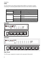
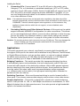
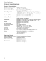
Powered by Accton
5/8-Port Gigabit Switch
ES4005V
ES4008V
Installation Guide
www.edge-core.com
Quick Installation Guide
5-Port Gigabit Ethernet Switch
Gigabit Ethernet Switch with 5 10BASE-T / 100BASE-TX / 1000BASE-T
(RJ-45) Ports
8-Port Gigabit Ethernet Switch
Gigabit Ethernet Switch with 8 10BASE-T / 100BASE-TX / 1000BASE-T
(RJ-45) Ports
ES4005V
ES4008V
E032005-R01
150000017400H
Contents
Introduction
Features and Benefits
Front Panel RJ-45 Ports
LEDs
ES4005V
ES4008V
Rear Panel
1
1
1
2
2
2
2
Installing the Switch
Package Contents
Selecting a Site
Instructions
Applications
3
3
3
3
4
Product Specifications
Physical Characteristics
Switching Criteria
6
6
6
Troubleshooting
Diagnosing Switch Indicators
Power and Cooling Problems
Installation
7
7
7
7
Cables
Cable Specifications
10BASE-T/100BASE-TX Pin Assignments
1000BASE-T Pin Assignments
1000BASE-T Cable Requirements
Cable Testing for Existing Category 5 Cable
Adjusting Existing Category 5 Cabling
8
8
8
9
9
9
10
EMI Certification
FCC Class B Certification (USA)
Canada Department of Communications – Class B
CE Mark Declaration of Conformance for EMI and Safety (EEC)
10
10
10
11
Safety Compliance
12
i
Contents
ii
Introduction
These switches are high-performance Gigabit Ethernet switches designed for
delivering Gigabit connectivity to the desktop. They provide 5/8 full-duplex
1000BASE-T ports that significantly improve network performance and boost
throughput for high-bandwidth applications. With 10/16 Gigabits of aggregate
bandwidth, these switches provide the quickest solution to meeting the growing
demands on your network's limited resources.
Features and Benefits
• Auto-negotiation supported on all ports
• Automatic MDI/MDI-X operation
• IEEE Std 802.3-2002 compliance ensures compatibility with standards-based
hubs, switches and cards from any vendor
• Store-and-forward switching ensures error-free transmission
• Half- and full-duplex flow control prevents packets from being dropped under
heavy loading
• Plug-and-play nothing to configure
• “At-a-glance” LEDs for port and system status monitoring
• Desktop installation
Front Panel RJ-45 Ports
These switches feature 5/8 1000BASE-T ports with RJ-45 connectors located on the
rear panel of the switch. Because all ports support automatic MDI/MDI-X operation,
you can use straight-through cables for all network connections to PCs or servers, or
to other switches or hubs.
1
Introduction
LEDs
The front panel of the switch provides status LEDs for “at-a-glance” system
monitoring. The following table details the functions of the various indicators.
LED
Power
Ports
Link/Act
Port and System Status LEDs
Condition
Status
On
The switch is receiving power.
Off
The switch is not receiving power.
On
Off
1000M
Flashing
On
Off
The port has established a valid network
connection.
The port has not established a network
connection.
Traffic is passing through the port.
Indicates the port is operating at 1000 Mbps.
Indicates the port is not operating at 1000 Mbps.
ES4005V
ES4008V
Rear Panel
The DC power receptacle is located on the rear panel of the switch.
2
Package Contents
Installing the Switch
Before installing the switch, verify that you have all the items listed under “Package
Contents.” If any of the items are missing or damaged, contact your local Accton
distributor. Also be sure you have all the necessary tools and cabling before
installing the switch. Note that the switch can be installed on any suitable large flat
suface.
Package Contents
This package includes:
• 5/8-Port Gigabit Ethernet Switch (ES4005V or ES4008V)
• Four rubber foot pads
• Appropriate DC power adapter
• This User Guide
Selecting a Site
Be sure to follow the site selection guidelines below when choosing a location:
• Select a suitable location for the switch:
• It should be accessible for installing, cabling and maintaining the switch.
• The temperature and humidity should be within the ranges listed in the
specifications.
• The status LEDs should be clearly visible.
• There should be adequate space (approximately two inches) on all sides for
proper air flow.
• Make sure twisted-pair cable is always routed away from power lines, fluorescent
lighting fixtures and other sources of electrical interference such as radios,
transmitters, etc.
• Make sure that a properly grounded power outlet is within 1.83 meters (6 feet) of
the switch and is powered from an independent circuit breaker. As with any
equipment, using a filter or surge suppressor is recommended.
Instructions
1.
2.
Positioning the Switch: For desktop or shelf mounting, attach the four
adhesive foot pads to the bottom of the switch.
Applying Power: Plug one end of the power adapter into the socket on the
switch's rear panel, and the other end into an appropriate electrical outlet.
Check the Power LED to be sure power is on.
Note: It is not necessary to power off the switch before connecting or disconnecting any
UTP cables, as these actions will not disrupt the operation of other devices
attached to the switch.
3
Installing the Switch
3.
Connecting PCs: Connect each PC to an RJ-45 port on the switch using
Category 5, 5e, or 6 shielded or unshielded twisted-pair (UTP or STP) cable,
maximum length 100 meters (328 ft). Switch 10/100/1000 will support up to 5/8
PCs. All ports on the switch support automatic MDI/MDI-X operation, so you
can use straight-through cables for all network connections to PCs or servers,
or to other switches or hubs.
Note: If an attached device does not support auto-negotiation, the data rate will be
sensed automatically and the communication mode will default to half duplex. (All
1000BASE-T devices should support auto-negotiation, so this behavior only
applies to slower devices which do not support, or have disabled, autonegotiation.)
4.
Cascading Switches and Other Network Devices: All the ports on the switch
support automatic MDI/MDI-X configuration for cable connections. This allows
you to use straight-through cable to connect to other switches or hubs from any
port on the switch. No crossover cables or other device settings are needed.
See the “Cable Specifications” on page 8 of this guide for further information.
Caution: Do not plug a phone jack connector into any RJ-45 port. This may damage the
switch. Instead, use only twisted-pair cables with RJ-45 connectors that
conform with FCC standards.
Applications
This switch segments your network, significantly increasing both bandwidth and
throughput. Each port on the switch can be attached to any Ethernet, Fast Ethernet,
or Gigabit Ethernet device, such as another switch, or a server’s network adapter.
All switch ports operate at 10 /100 Mbps full and half duplex, or 1000 Mbps full
duplex, providing up to 2 Gbps of bandwidth to the attached device.
Bridging Functions – This switch provides fully transparent bridging functions.
It automatically learns node addresses, that are subsequently used to filter and
forward all traffic based on the destination address. When traffic passes between
devices attached to the same shared collision domain, those packets are filtered
from the switch. But when traffic must be passed between unique segments
(i.e., different ports on the switch), the high-speed switching fabric forwards the
packets at near zero latency.
Switching Functions – Store-and-forward switching is used to forward traffic to
other ports. This scheme ensures data integrity and provides a clean data stream.
Sample Application – This switch is designed to operate as a small workgroup
switch. It can provide 10, 100, or 1000 Mbps connections to workstations, or 1000
Mbps full-duplex links to high-speed servers. It can also provide a high-bandwidth
uplink to the network backbone.
4
Applications
V
100 Mbps
10 Mbps
100 Mbps
1000 Mbps
100 Mbps
Server
10 Mbps Workstations
100 Mbps Workstation
1000 Mbps Workstation
Standalone LAN
V
V
100 Mbps
Servers
100 Mbps Workstations
1000 Mbps Workstation
100 Mbps
Server
1000 Mbps
Workstation
10 Mbps
Segment
100 Mbps
Segment
Cascading Switches
5
Product Specifications
Product Specifications
Physical Characteristics
Standards Conformance
Communication Rate
Communication Mode
Media Supported
Number of Ports
Indicator Panel
Dimensions
Weight
DC Input Power
Power Consumption
Temperature
Humidity
Immunity
Emissions
Safety
IEEE Std 802.3-2002
10. 100, and 1000 Mbps
Full or half duplex at 10/100 Mbps
Full duplex at 1000 Mbps
10BASE-T: 100-ohm Category 3 or better twisted-pair
100BASE-TX: 100-ohm Category 5 or better twisted pair
1000BASE-T: 100-ohm Category 5, 5e, or 6 twisted-pair
ES4005V: 5 RJ-45 1000BASE-T ports
ES4008V: 8 RJ-45 1000BASE-T ports
Power
Ports: Link/Act, 1000 Mbps
ES4005V: 13.0 x 8.56 x 31.9 cm (5.15 x 3.38 x 1.26 in.)
ES4008V: 17.46 x 8.6 x 3.29 cm (6.9 x 3.4x 1.3 in.)
ES4005V: 275 g (0.606 lb)
ES4008V: 375 g (0.827 ib)
9V, 1A
All 9 Watts maximum
Operating: 0 ~ 40 ºC / 32 ~ 98 ºF
Storage: -40 ~ 70 ºC / -40 ~ 158 ºF
10% to 90% non-condensing
EN 61000-4-2/3/4/5/6/8/11
FCC Class B, CISPR Class B, EN 61000-3-2/3
CSA/CUS (CSA60950-1 & UL60950-1)
TÜV/GS (EN60950-1)
CB (IEC60950-1)
Switching Criteria
Network Bridging Function Filtering, forwarding and learning
Switching Method
Store-and-forward
MAC Address Table
ES4005V: 4K entries
ES4008V: 8K entries
Packet buffer
ES4005V: 112 KBytes
ES4008V: 144 KBytes
6
Troubleshooting
Diagnosing Switch Indicators
Symptom
Power LED does not light after power on.
Probable Causes
DC power adapter may be defective.
Possible Solutions
• Check for loose connections.
• Check the power outlet by using it for another device.
• Replace the DC power adapter.
Symptom
Port (link) LED does not light after connection is made.
Probable Causes
Switch port, network card or cable may be defective.
Possible Solutions
• Check that the switch and attached device are both powered on.
• Be sure the network cable is connected to both devices.
• Verify that Category 5 or better cable is used for 10/100 Mbps connections,
Category 5, 5e, or 6 cable for 1000 Mbps connections, and that the length of any
cable does not exceed 100 meters (328 feet).
• Check the network card and cable connections for defects.
• Replace the defective card or cable if necessary.
Power and Cooling Problems
If the power indicator does not turn on when the power cord is plugged in, you may
have a problem with the power outlet, power cord, or internal power supply as
explained in the previous section. However, if the unit powers off after running for a
while, check for loose power connections, power losses or surges at the power
outlet, and verify that the fans on the right side of the unit are unobstructed and
running prior to shutdown. If you still cannot isolate the problem, then the internal
power supply may be defective.
Installation
Verify that all system components have been properly installed. If one or more
components appear to be malfunctioning (e.g., the power cord or network cabling),
test them in an alternate environment where you are sure that all the other
components are functioning properly.
7
Cables
Cable Specifications
Cable Types and Specifications
Cable
Type
Max. Length
Connector
10BASE-T
Cat. 3, 4, 5 100-ohm UTP
100 m (328 ft)
RJ-45
100BASE-TX
Cat. 5 100-ohm UTP
100 m (328 ft)
RJ-45
1000BASE-T
Cat. 5, 5e, 6 100-ohm UTP
100 m (328 ft)
RJ-45
Caution: DO NOT plug a phone jack connector into
any RJ-45 port. Use only twisted-pair cables
with RJ-45 connectors that conform with
FCC standards.
1
8
8
1
Use 100-ohm unshielded twisted-pair (UTP) or
shielded twisted-pair (STP) cable for RJ-45
connections: Category 3, 4, or 5 cable for 10 Mbps connections,
Category 5, 5e cable for 100 Mbps connections, or Category 5, 5e or 6 for
1000 Mbps connections. Also be sure that the length of any twisted-pair connection
does not exceed 100 meters (328 feet).
10BASE-T/100BASE-TX Pin Assignments
Because all ports on this switch support automatic MDI/MDI-X operation, you can
use straight-through cables for all network connections to PCs or servers, or to other
switches or hubs. In straight-through cable, pins 1, 2, 3, and 6, at one end of the
cable, are connected straight through to pins 1, 2, 3 and 6 at the other end of the
cable.
The table below shows pinout signals for connections to 10BASE-T/100BASE-TX
devices.
8
Pin
MDI-X Signal Name
MDI Signal Name
1
Receive Data plus (RD+)
Transmit Data plus (TD+)
2
Receive Data minus (RD-)
Transmit Data minus (TD-)
3
Transmit Data plus (TD+)
Receive Data plus (RD+)
6
Transmit Data minus (TD-)
Receive Data minus (RD-)
4,5,7,8
Not used at 10/100 Mbps
Not used at 10/100 Mbps
1000BASE-T Pin Assignments
The table below shows the 1000BASE-T MDI and MDI-X port pinouts. These ports
require that all four pairs of wires be connected. Note that for 1000BASE-T
operation, all four pairs of wires are used for both transmit and receive.
Use 100-ohm Category 5 or 5e unshielded twisted-pair (UTP) or shielded twistedpair (STP) cable for 1000BASE-T connections. Also be sure that the length of any
twisted-pair connection does not exceed 100 meters (328 feet).
Pin
MDI-X Signal Name
MDI Signal Name
1
Bi-directional Data Two Plus (BI_D2+)
Bi-directional Data One Plus (BI_D1+)
2
Bi-directional Data Two Minus (BI_D2-)
Bi-directional Data One Minus (BI_D1-)
3
Bi-directional Data One Plus (BI_D1+)
Bi-directional Data Two Plus (BI_D2+)
4
Bi-directional Data Four Plus (BI_D4+)
Bi-directional Data Three Plus (BI_D3+)
5
Bi-directional Data Four Minus (BI_D4-)
Bi-directional Data Three Minus (BI_D3-)
6
Bi-directional Data One Minus (BI_D1-)
Bi-directional Data Two Minus (BI_D2-)
7
Bi-directional Data One Plus (BI_D3+)
Bi-directional Data One Plus (BI_D4+)
8
Bi-directional Data Three Minus (BI_D3-)
Bi-directional Data Four Minus (BI_D4-)
1000BASE-T Cable Requirements
All Category 5 UTP cables that are used for 100BASE-TX connections should also
work for 1000BASE-T, providing that all four wire pairs are connected. However, it is
recommended that for all critical connections, or any new cable installations,
Category 5e (enhanced Category 5) cable should be used. The Category 5e
specification includes test parameters that are only recommendations for
Category 5. Therefore, the first step in preparing existing Category 5 cabling for
running 1000BASE-T is a simple test of the cable installation to be sure that it
complies with the IEEE 802.3ab standards.
Cable Testing for Existing Category 5 Cable
Installed Category 5 cabling must pass tests for Attenuation, Near-End Crosstalk
(NEXT), and Far-End Crosstalk (FEXT). This cable testing information is specified in
the ANSI/TIA/EIA-TSB-67 standard. Additionally, cables must also pass test
parameters for Return Loss and Equal-Level Far-End Crosstalk (ELFEXT). These
tests are specified in the ANSI/TIA/EIA-TSB-95 Bulletin, “The Additional
Transmission Performance Guidelines for 100 Ohm 4-Pair Category 5 Cabling.”
Note that when testing your cable installation, be sure to include all patch cables
between switches and end devices.
9
EMI Certification
Adjusting Existing Category 5 Cabling
If your existing Category 5 installation does not meet one of the test parameters for
1000BASE-T, there are basically three measures that can be applied to try to correct
the problem:
1.
2.
3.
Replace any Category 5 patch cables with high-performance Category 5e
cables.
Reduce the number of connectors used in the link.
Reconnect some of the connectors in the link.
EMI Certification
FCC Class B Certification (USA)
Warning: This equipment generates, uses, and can radiate radio frequency energy
and, if not installed and used in accordance with the instruction manual, may cause
interference to radio communications. It has been tested and found to comply with
the limits for a Class B digital device pursuant to Subpart B of Part 15 of FCC Rules,
which are designed to provide reasonable protection against such interference when
operated in a commercial environment. Operation of this equipment in a residential
area is likely to cause interference, in which case the user, at his own expense, will
be required to take whatever measures are required to correct the interference.
You may use unshielded twisted-pair (UTP) for RJ-45 connections - Category 3 or
greater for 10 Mbps connections, Category 5 for 100 Mbps connections and
Category 5, 5e, or 6 for 1000 Mbps connections.
Canada Department of Communications – Class B
This digital apparatus does not exceed the Class B limits for radio noise emissions
from digital apparatus as set out in the interference-causing equipment standard
entitled “Digital Apparatus,” ICES-003 of the Department of Communications.
Cet appareil numérique respecte les limites de bruits radioélectriques applicables
aux appareils numériques de Classe B prescrites dans la norme sur le matériel
brouilleur: “Appareils Numérques,” NMB-003 édictée par le ministère des
Communications.
10
CE Mark Declaration of Conformance for EMI and Safety (EEC)
This information technology equipment complies with the requirements of the
Council Directive 89/336/EEC on the Approximation of the laws of the Member
States relating to Electromagnetic Compatibility and 73/23/EEC for electrical
equipment used within certain voltage limits and the Amendment Directive
93/68/EEC. For the evaluation of the compliance with these Directives, the following
standards were applied:
RFI
• Limit class B according to EN 55022:1998
Emission: • Limit class A for harmonic current emission according to
EN 61000-3-2/1995
• Limitation of voltage fluctuation and flicker in low-voltage
supply system according to EN 61000-3-3/1995
Immunity: • Product family standard according to EN 55024:1998
• Electrostatic Discharge according to EN 61000-4-2:1995
(Contact Discharge: ±4 kV, Air Discharge: ±8 kV)
• Radio-frequency electromagnetic field according to
EN 61000-4-3:1996
(80 - 1000 MHz with 1 kHz AM 80% Modulation: 3 V/m)
• Electrical fast transient/burst according to EN 61000-4-4:1995
(AC/DC power supply: ±1 kV, Data/Signal lines: ±0.5 kV)
• Surge immunity test according to EN 61000-4-5:1995
(AC/DC Line to Line: ±1 kV, AC/DC Line to Earth: ±2 kV)
• Immunity to conducted disturbances, Induced by radiofrequency fields: EN 61000-4-6:1996
(0.15 - 80 MHz with 1 kHz AM 80% Modulation: 3 V/m)
• Power frequency magnetic field immunity test according to
EN 61000-4-8:1993 (1 A/m at frequency 50 Hz)
• Voltage dips, short interruptions and voltage variations
immunity test according to EN 61000-4-11:1994
(>95% Reduction @10 ms, 30% Reduction @500 ms, >95%
Reduction @5000 ms)
LVD:
• EN 60950-1
Warning! Do not plug a phone jack connector in the RJ-45 port. This may damage
the device. Les raccordeurs ne sont pas utilisé pour le système téléphonique!
11
Safety Compliance
Safety Compliance
Please read the following safety information carefully before
installing the switch:
Warning:
Installation and removal of the unit must be carried out by qualified personnel
only.
Warning:
Do not plug a phone jack connector in the RJ-45 port. This may damage this
device.
Achtung:
Les raccordeurs ne sont pas utilisés pour le systéme téléphonique!
Warning:
This product does not contain any serviceable user parts.
Warning:
When connecting this device to a power outlet, connect the field ground lead on
the tri-pole power plug to a valid earth ground line to prevent electrical hazards.
Caution:
Do not plug a phone jack connector in the RJ-45 port. This may damage this
device. Les raccordeurs ne sont pas utilisé pour le systéme téléphonique!
Caution:
Use only twisted-pair cables with RJ-45 connectors that conform to FCC
standards.
Achtung:
Dieses Produkt enthélt keine Teile, die eine Wartung vom Benutzer benétigen.
• This unit operates under SELV (Safety Extra Low Voltage) conditions according to
IEC 60950. The conditions are only maintained if the equipment to which it is
connected also operates under SELV conditions.
Veuillez lire a fond l'information de la securite suivante avant
d'installer le Switch:
AVERTISSEMENT: L’installation et la dépose de ce groupe doivent être confiés à un
personnel qualifié.
• L’appareil fonctionne à une tension extrêmement basse de sécurité qui est
conforme à la norme IEC 60950. Ces conditions ne sont maintenues que si
l’équipement auquel il est raccordé fonctionne dans les mêmes conditions.
France et Pérou uniquement:
Ce groupe ne peut pas être alimenté par un dispositif à impédance à la terre. Si vos
alimentations sont du type impédance à la terre, ce groupe doit être alimenté par une
tension de 230 V (2 P+T) par le biais d’un transformateur d’isolement à rapport 1:1, avec
un point secondaire de connexion portant l’appellation Neutre et avec raccordement
direct à la terre (masse).
Bitte unbedingt vor dem Einbauen des Switches die folgenden
Sicherheitsanweisungen durchlesen:
WARNUNG: Die Installation und der Ausbau des Geräts darf nur durch Fachpersonal
erfolgen.
• Der Betrieb dieses Geräts erfolgt unter den SELV-Bedingungen
(Sicherheitskleinstspannung) gemäß IEC 60950. Diese Bedingungen sind nur
gegeben, wenn auch die an das Gerät angeschlossenen Geräte unter SELVBedingungen betrieben werden.
12
ES4005V
ES4008V
E032005-R01
150000017400H