1
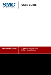
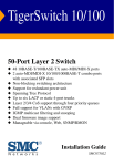
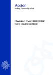
CheetahSwitch Workgroup-3518
User Guide
User Guide
CheetahSwitch Workgroup-3518
Intelligent Fast Ethernet Switch
with 16 10BASE-T / 100BASE-TX (RJ-45) Ports,
and 2 Slots for Optional 2-Port Fiber Module
or 2-Port Gigabit Uplink Module
Copyright © 1999 by Accton Technology Corporation. All rights reserved.
No part of this document may be copied or reproduced in any form or by any means without the prior
written consent of Accton Technology Corporation.
Accton makes no warranties with respect to this documentation and disclaims any implied warranties
of merchantability, quality, or fitness for any particular purpose. The information in this document is
subject to change without notice. Accton reserves the right to make revisions to this publication
without obligation to notify any person or entity of any such changes.
International Headquarters
No. 1 Creation Road III,
Science-based Industrial Park
Hsinchu 300, Taiwan, R.O.C.
Phone: 886-3-5770-270
FAX: 886-3-5770-267
Internet: [email protected]
USA Headquarters
P.O. Box 51420
Irvine, CA 92619-1420
Phone Numbers Sales: 888-398-2101 or 949-707-4800
Support: 888-398-4101 or 949-707-4847
RMA:
888-398-3101 or 949-707-4828
FAX: 949-707-2460
Accton is a trademark of Accton Technology Corporation. Other trademarks or brand names
mentioned herein are trademarks or registered trademarks of their respective companies.
ES3518
E0599-R01
150015-102
Contents
Introduction
1
Installing the Switch
1
Package Contents
Description of Hardware
Mounting the Switch
Stacking Switches on a Flat Surface
Mounting Switches in a Rack
Installing an Optional Module
Connecting the Switch System
Making a Connection via an RJ-45 Station Port
Making a Connection via an MDI Daisy-Chain Port
Connecting to a Fiber Optic Port
Connecting to a Gigabit Uplink Port
Powering On the Switch
Verifying Port Status
Verifying System Operation
Applications
Configuring the Switch
Making the Connections Required for System Configuration
Onsite Connection
Telnet Connection
In-Band Network Connection
Configuring Your System with the Console Interface
Using the System Configuration Program
Configuring the Switch
Setting System Information and SNMP Parameters
Configuring Port Parameters
Configuring Port Trunks
Using a Sniffer Port for Analysis
Using the Spanning Tree Algorithm
Using Virtual LANs
Setting the Network Address
Setting User Names and Passwords
Setting the Serial Port Baud Rate
Restoring Factory Defaults
Testing a Network Connection with Ping
Displaying Status Reports
Displaying
Displaying
Displaying
Displaying
Port Status
Port Traffic Status
Port Frame Types
Port Frame Sizes
2
2
3
3
3
4
4
4
5
6
6
6
7
7
8
9
9
9
10
10
10
11
12
12
13
15
16
17
20
23
23
24
24
25
25
26
26
27
28
i
Displaying Port Status for the Spanning Tree
Product Specifications
Base Unit
Physical Characteristics
Switching Criteria
Traffic Control
System Management
Media Expansion Modules
Fiber Optic Module (EM3572-FX-SC)
Gigabit Uplink Module (EM4572-SX-SC)
Troubleshooting
29
30
30
30
31
31
31
31
31
32
32
Diagnosing Switch Indicators
Power and Cooling Problems
Installation
In-Band Access
32
32
33
33
Port and Cable Assignments
33
RJ-45 Port Description
DB9 Serial Port Pin Description
DB9 Port Pin Assignments
Connection from Switch's Serial Port to PC's 9-Pin COM Port
Connection from Switch's Serial Port to Modem's 25-Pin DCE Port
Connection from Switch's Serial Port to PC's 25-Pin DTE Port
EMI Certification
FCC Class A Certification (USA)
Canada Department of Communications - Class A
Class A (Taiwan)
VCCI Class A Compliance (Japan)
CE Mark Declaration of Conformance for EMI and Safety (EEC)
Safety Compliance
Warning: Fiber Optic Port Safety
Avertissment: Ports pour fibres optiques - sécurité sur le plan optique
Warnhinweis: Faseroptikanschlüsse - Optische Sicherheit
Underwriters Laboratories Inc. (USA)
Wichtige Sicherheitshinweise (Germany)
33
34
34
34
34
35
35
35
35
35
36
36
36
36
36
36
37
37
Warranty
38
Optional Items
38
ii
User Guide
Introduction
The CheetahSwitch Workgroup-3518 is a high-density
switch that’s perfect for moving large workgroups from
conventional 10Mbps Ethernet to multiple-segment
100Mbps Fast Ethernet. This switch delivers dedicated
100Mbps links to each attached LAN segment (independent
collision domain) or any PC attached directly to the switch –
all with conventional cabling and adapters. It completely eliminates
the bottlenecks of shared 10Mbps Ethernet networks by providing a wide
bandwidth of up to 3.6 Gbps. This makes it ideal for increasing the throughput of
interconnected Ethernet / Fast Ethernet hubs or server farms.
This switch also includes two slots for an optional 100Mbps fiber optic module that
can connect to a remote site up to 2 kilometers (1.24 miles) away, or for a Gigabit
module that can be used to uplink to a collapsed Gigabit backbone or for a highspeed server connection.
Moreover, this switch provides a wide array of advanced features:
• Spanning Tree Algorithm for redundant paths between switches
• VLANs for segregating broadcast domains into port groups (IEEE 802.1Q)
• Link Aggregation for creating fat pipes between switches
• Traffic Prioritization based on port or VLAN tags
• Broadcast storm control (broadcast packets dropped above a fixed threshold)
• Flow control (back pressure for half duplex, IEEE 802.3x for full duplex)
• Port mirroring (for real-time debugging without affecting the target port)
• Four-group RMON (including Statistics, History, Alarms and Events)
The CheetahSwitch Workgroup-3518 includes management software that allows
you to configure or monitor the switch using its on-board management program,
or other SNMP/RMON applications. To manage the switch, you can make
a direct connection to the console port. You can also make a network connection
to manage the switch using Telnet, the on-board Web Agent, or Accton’s free
Windows-based network management software called EliteView.
Installing the Switch
Before installing the switch verify that you have all the items listed under
“Package Contents.” If any of the items are missing or damaged, contact your
local Accton distributor. Also be sure you have all the necessary tools and
cabling before installing the switch. Note that this switch can be installed on any
suitably large flat surface or in a standard EIA 19-inch rack. After installing the
switch, refer to “Configuring the Switch” on page 9 to set up its more advanced
features, such as Spanning Tree Protocol, VLANs, and Port Trunking.
1
1
CheetaSwitch Workgroup-3518
Package Contents
The CheetahSwitch Workgroup-3518 includes:
•
•
•
•
CheetahSwitch Workgroup-3518 (Model No. ES3518)
Intelligent Fast Ethernet Switch
with 16 10BASE-T / 100BASE-TX (RJ-45) Ports,
and 2 Slots for Optional Fiber Module or Gigabit Uplink Module
Four rubber foot pads
• User Guide
Rack mount bracket kit
• Owner registration card
AC power cord
Description of Hardware
The CheetahSwitch Workgroup-3518 base unit contains 16 10BASE-T /
100BASE-TX ports. It also has two slots for optional media expansion modules,
including a slot on the front panel for a Fast Ethernet fiber optic module with two
100BASE-FX (SC type) ports, and a slot on the rear panel for a Gigabit uplink
module with two 1000BASE-SX (SC type) ports. (Also, note that the Network
Management Module is included as part of the default package.)
All RJ-45 ports operate at 10 or 100 Mbps, and support auto-negotiation, and
half or full duplex. The 100BASE-FX module is fixed at 100Mbps, and supports
half or full duplex via manual configuration. The Gigabit ports are fixed at 2Gbps,
full duplex. When using auto-negotiation for the RJ-45 ports, the transmission
mode will be automatically set if this feature is also supported by the attached
device. Otherwise, the mode can be set for any connection using the on-board
configuration program.
Note: When a 100BASE-FX module is installed, RJ-45 Ports 15 and 16 are disabled.
A toggle switch is also included on Port 1 for an MDI connection, which allows
you to connect directly to another switch or hub with straight-through twisted-pair
cable. It also includes a display panel for key system and port indications that
simplifies installation and network troubleshooting.
The following figure shows the components of this switch:
2
User Guide
Mounting the Switch
This switch can be placed directly on your desktop, or mounted in a rack.
Before you start installing the switch, make sure you can provide the right
operating environment, including power requirements, sufficient physical space,
and proximity to other network devices that are to be connected. Verify the
following installation requirements:
• Power requirements: 100 to 240 VAC (± 10%) at 50/60 Hz (± 3Hz). The
switch's power supply automatically adjusts to the input voltage level.
• The switch should be located in a cool dry place, with at least 10 cm. (4 in.) of
space on the sides for ventilation.
• Place the switch out of direct sunlight, and away from heat sources or areas
with a high amount of electromagnetic interference.
• If you intend to mount the switch in a rack, make sure you have all the
necessary mounting screws, brackets, bolts and nuts, and the right tools.
• Check if network cables and connectors needed for installation are available.
Stacking Switches on a Flat Surface
The CheetahSwitch can be stacked
anywhere there is enough flat space,
such as on a table or desktop.
1. Stick the self-adhesive rubber foot pads (that come
with this package) on each of the 4 concave spaces located on the bottom of
the first switch.
2. Place the first switch on a firm flat surface where you want to install the stack.
3. Repeat step 1 for each switch before stacking them. The rubber foot pads
cushion the switch against shock/vibrations and provide space between each
switch for ventilation.
Mounting Switches in a Rack
Please comply with the following
instructions to ensure that your switch
is securely mounted in the rack.
1. Use a standard EIA 19-inch rack.
2. Use the brackets and screws supplied in the rack mounting kit.
3. Use a cross-head screwdriver to attach the brackets to the side
of the switch.
4. Position the switch in the rack by lining up the holes in the brackets with the
appropriate holes on the rack, and then use the supplied screws to mount the
switch in the rack.
3
3
CheetaSwitch Workgroup-3518
Installing an Optional Module
The slots on the switch are provided for installing
optional media expansion modules – fiber optic on the
front and Gigabit on the rear. The fiber optic module can
be used to connect to remote sites, while the Gigabit
module can be used as a network backbone. You can
install a module as described below:
1. Disconnect power to the switch (modules are not hotswappable).
2. Remove the face plate on the media expansion slot by removing the two
screws with a flat-head screwdriver.
3. Before opening the package that contains the module, touch the bag to the
switch casing to discharge any potential static electricity.
4. Remove the module from the anti-static shielded bag.
5. Holding the module level, gently push it all the way into the expansion slot
along the guide rails, ensuring that it firmly engages with the connector.
6. If you are sure the module is properly mated with the connector, tighten the
retainer screws to secure the module in the expansion slot.
I
Media expansion modules are not hot-swappable. Be sure you power off the
switch before installing any of these modules.
Connecting the Switch System
The CheetahSwitch provides 16 RJ-45 ports on the base unit. Each of these
ports supports connection to 10Mbps Ethernet or 100Mbps Fast Ethernet, and
supports full or half-duplex operation. The transmission speed for each port is
automatically set by the switch to match the highest speed supported by the
connected device. The transmission mode can be set for each port using autonegotiation (if also supported by the attached device). However, if the device
attached to any port on the switch does not support auto-negotiation, you can
manually configure the transmission mode via the console port on the front
panel, or via an in-band connection (including Telnet, Web Agent or EliteView).
Making a Connection via an RJ-45 Station Port
You can connect any RJ-45 (MDI-X) station port on the switch to any device that
uses a standard network interface such as a workstation or server, or to a
network interconnection device such as a bridge or router (depending on the port
type implemented).
1. Prepare the network devices you wish to network. Make sure you have
installed 10BASE-T or 100BASE-TX network interface cards for connecting to
the switch's RJ-45 (MDI-X) station ports.
2. Prepare straight-through shielded or unshielded twisted-pair cables with
RJ-45 plugs at both ends. Use 100W Category 3, 4 or 5 cable for standard
4
User Guide
10Mbps Ethernet connections, or 100W Category 5 cable for 100Mbps Fast
Ethernet connections.
3. Connect one end of the cable to the RJ-45 port of the network interface card,
and the other end to any available (MDI-X) station port on the switch. All the
RJ-45 ports support 10Mbps and 100Mbps Ethernet connections. When
inserting an RJ-45 plug, be sure the tab on the plug clicks into position to
ensure that it is properly seated. Using the switch in a stand-alone configuration,
you can network up to 16 end nodes.
I Do not plug a phone jack connector into any RJ-45 port.
This may damage the
switch. Instead, use only twisted-pair cables with RJ-45 connectors that conform
with FCC standards.
Notes: 1. When using Port 1, set the selection switch to MDI-X.
2. Make sure each twisted-pair cable does not exceed 100 meters (328 feet).
3. We advise using Category 5 cable for all network connections to avoid
any confusion or inconvenience in the future when you upgrade attached
devices to Fast Ethernet.
Making a Connection via an MDI Daisy-Chain Port
To connect to another compatible switch or hub, take these steps:
1. Use Port 1 and set the daisy-chain switch to MDI.
2. Prepare straight-through shielded or unshielded twisted-pair cables with
RJ-45 plugs at both ends. Use 100W Category 3, 4 or 5 cable for standard
10Mbps Ethernet connections, or 100W Category 5 cable for 100Mbps Fast
Ethernet connections.
3. Connect one end of the cable to Port 1 on the switch, and the other end to
any MDI-X station port on the other device. When inserting an RJ-45 plug, be
sure the tab on the plug clicks into position to ensure that it is properly seated.
Notes: 1. Alternatively, you can connect from an MDI-X port on the switch to an
MDI daisy-chain port on the other device.
2. Make sure each twisted-pair cable does not exceed 100 meters (328 feet).
3. To connect to another switch or hub, you may also attach to (MDI-X)
station ports at both ends if you use crossover cabling. (Refer to “Port
and Cable Assignments” on page 33 for a description of crossover cable.)
Restrictions on Cascade Length - The IEEE 802.3 standard recommends
restricting the number of hubs (i.e., repeaters) cascaded via twisted-pair cable to 4;
while IEEE 802.3u provides even stricter recommendations for Fast Ethernet.
Therefore, when cascading devices other than this switch, please refer to the
accompanying documentation for cascade restrictions. However, note that because
switches break up the path for connected devices into separate collision domains,
you should not include the switch or connected cabling in your calculations for
cascade length involving other devices.
5
5
CheetaSwitch Workgroup-3518
Connecting to a Fiber Optic Port
If you connect fiber cable to the fiber optic
module on the front of the switch, be sure you use an SC-type connector. When
inserting the cable, be sure the tab on the plug clicks into position to ensure that
it is properly seated. If you use an SC-to-ST converter, run cable from the Rx
(Tx) port on the module to the Tx (Rx) port on the target device.
Note that the fiber optic ports operate only at 100 Mbps, but can be manually
configured to either full or half duplex. When using full duplex, you can run a
fiber optic link up to 2 kilometers (1.24 miles). However, when using half duplex,
you can only run a link up to 412 meters (0.25 miles).
I
The media expansion modules are not hot-swappable. Be sure you power off the
switch before installing any of these modules.
Notes: 1. When using the fiber ports, do not use RJ-45 Port 15 or 16 on the base unit.
2. As a general rule, the length of fiber optic cable for a single switched link
should not exceed 2 kilometers (1.24 miles). However, timing constraints
must also be considered when calculating the maximum cable length for
your specific environment.
Connecting to a
Gigabit Uplink Port
If you connect fiber cable to the Gigabit module on the switch, be sure you use an
SC-type connector. When inserting the cable, be sure the tab on the plug clicks into
position to ensure that it is properly seated. If you use an SC-to-ST converter, run
cable from the Rx (Tx) port on the module to the Tx (Rx) port on the target device.
Note that the Gigabit ports operate at 2 Gbps, full duplex. The maximum length
for fiber optic cable is listed in the following table.
Fiber Size
Fiber Bandwidth
62.5/125 micro n 160 MHz/km
200 MHz/km
50/125 micro n
400 MHz/km
500 MHz/km
Maximum Cable Length
2-220 m (7-722 ft)
2-275 m (7-902 ft)
2-500 m (7-1641 ft)
2-550 m (7-1805 ft)
Powering On the Switch
1. Plug the power cord into the power socket at the rear of the switch, and the
other end into a power outlet.
2. Check the LED marked Power on the front panel to see if it is on. The unit will
automatically select the setting that matches the connected input voltage.
Therefore, no additional adjustments are necessary when connecting it to any
input voltage within the range marked on the rear panel.
3. The switch performs a self-diagnostic test upon power-on. (Note that this test
takes about 10 seconds to complete.)
Note: The unit supports a "hot remove" feature which permits you to connect or
disconnect twisted-pair or fiber cables without powering off the switch and
without disrupting the operation of the devices attached to the switch.
6
User Guide
Verifying Port Status
Check each connection by viewing the port indicators shown in the following table.
LED
State
System
Po we r
On
RJ-45 Ports
Link/Act On
Flashing
100M
On
FDX/COL On
Off
Flashing
Indication
Switch is re ce iving p o we r.
Po rt has e stab lishe d a valid ne two rk co nne ctio n.
Traffic is p assing thro ug h the p o rt.
Co mmunicatio ns have b e e n se t at 100 Mb p s.
Po rt has b e e n se t to full d up le x.
Po rt has b e e n se t to half d up le x.
Two o r mo re d e vice s atte mp te d to transmit at the
same time . (No rmal situatio n und e r CSMA/CD.)
100M Fiber Ports (optional module on front panel)
Link
On
Po rt has e stab lishe d a valid ne two rk co nne ctio n.
TX
On
Traffic is b e ing transmitte d fro m this p o rt.
RX
On
Traffic is b e ing re ce ive d b y this p o rt.
Agent Module
STAT
On
Ag e nt Mo d ule is p o we re d o n.
Gigabit Ports (optional module on rear panel)
Link
On
Po rt has e stab lishe d a valid ne two rk co nne ctio n.
TX
On
Traffic is b e ing transmitte d fro m this p o rt.
RX
On
Traffic is b e ing re ce ive d b y this p o rt.
FDX
On
Po rt has b e e n se t to full d up le x.
Verifying System Operation
Verify that all attached devices have a valid connection. The switch monitors the
link status for each port. If any device is properly connected to the switch and
transmitting a link beat signal, the Link indicator will light up for the corresponding
port. If the Link indicator fails to light when you connect a device to the switch,
check the following items:
•
Be sure all network cables and connectors are properly attached to the
connected device and the switch.
•
See if your cable is functioning properly by using it for another port and
attached device that displays valid indications when connected to the network.
•
Be sure no twisted-pair cable exceeds 100 meters (328 feet). 100Mbps fiber
cable should be under 2 kilometers (1.24 mile) when operating at full duplex,
or under 412 meters (0.25 miles) when operating at half duplex. And the
Gigbit connection should be under 220m (722 ft) when using 62.5/125 µm
cable or under 500m (1640 ft) when using 50/125 µm cable.
7
7
CheetaSwitch Workgroup-3518
Applications
This switch segments your network, significantly increasing both bandwidth and
throughput. Any port on the switch can be attached to a hub (a shared collision
domain) or provide a dedicated link to a single network device (such as a
workstation or server). When a port on the switch is connected to a hub (a 10 or
100 Mbps repeater), the bandwidth provided by that port is shared by all the
devices connected to the attached hub. However, when a port is connected to
an end node or to a device that breaks up the collision domain (e.g., another
switch, bridge or router), the attached device has access to the full bandwidth
provided by that port.
Bridging Functions - This switch provides fully transparent bridging functions.
It automatically learns node addresses, that are subsequently used to filter and
forward all traffic based on the destination address. When traffic passes between
devices attached to the same shared collision domain, those packets are filtered
from the switch. But when traffic must be passed between unique segments (i.e.,
different ports on the switch), the high-speed switching fabric forwards the packets
at near zero latency.
Switching Functions - Store-and-forward switching is used to forward traffic to
other ports. This scheme ensures data integrity and provides a clean data stream.
Flexible Configuration - This switch is not only designed to segment your
network, but also to provide a wide range of options in setting up network
connections. It can be used as a simple stand-alone switch; or can be connected
with standard repeater hubs, switches, or other network interconnection devices in
various configurations.
Media Expansion Options - You can use a Fast Ethernet fiber module to
connect to remote sites up to 2 kilometers (1.24 miles) away, or a Gigabit module
to support applications, such as a switch-to-switch stacking interface, high-speed
access to file servers, or for connecting to a collapsed Gigabit backbone switch.
8
User Guide
Configuring the Switch
This switch can be managed through a direct console connection to the Agent
Module’s serial port, using Telnet to access the switch over the network, using a
standard browser to access the Agent Module’s embedded web agent, or with
SNMP-based network management software such as EliteView. Once you have
connected a terminal or PC to the serial port on the switch, you can perform
tasks such as:
•
•
•
•
•
•
•
•
•
•
•
Enable/disable any port
Set the communication mode for any port
Configure SNMP parameters
Select RMON options
Configure the switch to join a Spanning Tree
Add ports to network VLANs
Configure port trunks to create a fat pipe
Mirror data from a target port to an analysis port
Display system information or statistics
Download system firmware
Restart the system
Making the Connections Required for System Configuration
The switch includes a menu-driven configuration program. The ASCII interface
to this program can be accessed by making a direct connection to the serial
port on the Agent Module, or by a Telnet connection to the switch over the network.
This section describes how to access the menu-driven configuration program via:
•
Onsite connection
A terminal or workstation connected to the serial port on the Agent Module.
•
Telnet connection
A workstation connected to a remote switch via a Telnet connection.
It also describes how to access the embedded Web agent over the network using
any standard browser, or with EliteView network management software or other
third-party mangement software.
Onsite Connection
Attach a VT100 compatible terminal or a PC running a terminal emulation
program to the serial port on the Agent Module. Use the null-modem cable
provided with this package, or use a null modem connection that complies with
the wiring assignments shown in the back of this guide.
When attaching to a PC, set terminal emulation type to VT100, specify the port
used by your PC (i.e., COM 1~4), and then set communications to 8 data bits, 1
stop bit, no parity, and 19200 bps (for initial configuration). Also be sure to set
both handshaking and flow control to "none."
9
9
CheetaSwitch Workgroup-3518
Telnet Connection
Prior to accessing the switch via an in-band Telnet connection, you must first
configure it with a valid IP address, subnet mask, and default gateway using an
out-of-band connection or BOOTP protocol. After configuring the switch's IP
parameters, you can access the on-board configuration program from anywhere
within the attached network.
Note: Use the Network Configuration menu to specify the maximum number of
simultaneous Telnet connections that are supported by the system.
In-Band Network Connection
The on-board configuration program can be accessed using Telnet or a Web
browser (Internet Explorer 3.0 or above, or Netscape Navigator 3.0 or above)
from any computer attached to the network. It can also be managed from a
network computer using management software such as EliteView.
Notes: 1. Prior to accessing the switch via a direct network connection, first
configure it with a valid IP address, subnet mask, and default gateway
using an out-of-band connection or BOOTP protocol.
2. The on-board program only provides access to basic configuration
functions. To access the full range of SNMP mangement functions, you
must use SNMP-based network mangement software. Accton provides
Windows-based SNMP software called EliteView. If you require this
software, please contact your Accton distributor. Also note that
EliteView’s CheetahSwitch Manager module can be easily integrated into
most third-party management platforms.
Configuring Your System with the Console Interface
Once a direct connection to the serial port or a Telnet connection is established,
the login screen for the on-board configuration program appears as shown below.
CheetahSwitch Workgroup-3518
V1.0.5 S1 Mar 17 1999 (C) Copyright Accton Technology Corp.
User Name
: admin
Password
: *****
If this is your first time to log into the configuration program, then the default user
names are “admin” and “guest”, and passwords are null. The administrator has
Read/Write access to all configuration parameters and statistics. While the
guest has Read Only access to the management program. To open the Main
Menu, type “admin” for the user name and press <Enter> for the password.
10
User Guide
You should define a password, record it and put it in a safe place. If you have
not already done so, select Main Menu > Configuration > User Login Config and
enter a password. Note that passwords can consist of up to 14 alphanumeric
characters and are not case sensitive.
Configuration parameters are described in the following section.
Note: A user is allowed three attempts to enter the correct password; on the third failed
attempt the current connection is terminated.
Using the System Configuration Program
The following menu is displayed immediately after logging into the system. For a
detailed description of the menu items, refer to the following table.
CheetahSwitch-3518 Version 1.0.5 S1 Mar 17 1999 Rev1
!!!!!
M A I N
M E N U
!!!!!
1) CONFIGURATION
2) UTILITY
3) REPORT
4) LOGOUT
** USE ARROW KEYS TO MOVE, ENTER KEY TO SELECT AND SPACE BAR TO CHANGE **
Note: Options for the currently selected item are displayed in the highlighted area at
the bottom of the interface screen.
With the system configuration program you can define system parameters,
manage and control the switch and all its ports, or monitor network conditions.
The table below briefly describes the menu structure.
Menu
Main Menu
Configuration
System
Port
Port Trunking
Port Mirror
Spanning Tree
VLAN
Protocol
User Login
11
Description
The top-level menu displayed after logging into the configuration program.
Contains all the switch configuration menus.
Provides system description, including name and other data. Also includes
community access strings, IP address of trap manager, and BOOTP option.
Disables/enables any port; sets communication mode to 10 or 100 Mbps, or
auto-negotiation. Also sets port parameters for Spanning Tree Algorithm.
Specifies ports to use for a trunk.
Specifies analysis and monitored port.
Defines spanning tree configuration for this switch.
Assigns ports to VLAN groups.
Sets IP address, subnet mask, and default gateway.
Sets user names and passwords for system access.
11
CheetaSwitch Workgroup-3518
Menu
Serial Port / Timeout
Load Default
Utility
Ping
Report
Port Status
LAN Port Data
LAN Port Frame Type
LAN Port Frame Size
Port Spanning Tree
Logout
Description
Sets baud rate for serial port.
Restores factory default configuration.
Contains network utilities.
Allows you to ping a specified IP address directly from the console.
Displays status of Ethernet traffic and Spanning Tree for each port.
Displays communication parameters for every port.
Displays statistics for the traffic crossing each port.
Displays distribution of frame types crossing each port.
Displays distribution of frame sizes crossing each port.
Displays values for port state, path cost, and port priority.
Exits the configuration program.
Configuring the Switch
Use the Configuration menus to set port communication mode, to control
management access to the switch, or to configure any of the advanced functions,
including port trunking, port mirror, Spanning Tree, and VLANs.
Setting System Information and SNMP Parameters
Use the System Configuration screen to display descriptive information about the
switch, to configure management access, or to set BOOTP protocol.
This screen is used to display and modify parameters for the Simple Network
Management Protocol (SNMP). The Agent Module monitors the hardware status
of the switch, as well as the traffic passing through the ports. A Network Management
Station (NMS) can access this information using Accton’s EliteView or other thirdparty network management software. Access rights to the agent are controlled
by community strings. To communicate with the agent, the NMS must first submit
a valid community string for authentication. The options for configuring community
strings and related trap functions are described in the following figure and table:
CheetahSwitch-3518 Version 1.0.5 S1 Mar 17 1999 Rev1
!!!!!
SYSTEM CONFIGURATION
DESCRIPTION:
CONTACT:
NAME:
LOCATION:
MAC:
COMMUNITY (READ):
COMMUNITY (WRITE/READ):
IP ADDR (TRAP):
COMMUNITY (TRAP):
BOOTP OPTION:
!!!!!
ES3518
Gloria
Test Switch
Sunnyvale
00:e0:61:12:34:58
public
private
10.1.104.1
trap
NORMAL
SAVE PREV NEXT MAIN
** USE ARROW KEYS TO MOVE, ENTER KEY TO SELECT AND SPACE BAR TO CHANGE **
12
User Guide
Parameter
Description
Contact1
Name1
Location1
MAC
Community (Read)
Community (Write/Read)
IP ADDR (Trap)
Description
System hardware description.
Contact person for the system.
Name assigned to the system.
Specifies the area or location where the system resides.
Physical address of the switch’s network interface.
The community name for SNMP read-only access to the device.
The community name for SNMP read/write access to the device.
Specifies IP address of management stations that will receive authentication failure messages or other traps messages from the switch.
Assigns SNMP access based on specified community strings.
The default IP address assigned to this agent. This address is used
only until you assign a new address to the agent, or after
downloading new firmware to the Agent Module.
Community (Trap)
BOOTP Option
1: Maximum string length is 255, but the screen only displays 44 characters. You can use the arrow keys
to browse the whole string.
Configuring Port Parameters
Use the Port Configuration screen to configure the transmission mode and
Spanning Tree parameters for any port on the switch. (Also refer to “Using the
Spanning Tree Algorithm” on page 18.) In addition to the functional parameters
listed below, note that you can also enable/disable any port. Use the PORT
SCROLL field to display the configuration for any port.
CheetahSwitch-3518 Version 1.0.5 S1 Mar 17 1999 Rev1
!!!!!
PORT CONFIGURATION
!!!!!
PORT NUMBER:
1
SPEED:
100
PORT NAME:
PORT 1
PATH COST:
19
PORT ENABLE:
YES
PORT PRIORITY:
128
AUTO NEGOTIATION:
YES
TRAFFIC PRIORITY: DEFAULT
DUPLEX:
FULL
FLOW CONTROL:
DISABLE
SAVE PREV MAIN
** USE ARROW KEYS TO MOVE, ENTER KEY TO SELECT AND SPACE BAR TO CHANGE **
Name
Description
Port Number
Port identification number.
Port Name
Port Enable
Port reference name assigned by user.
Allows you to disable a port due to abnormal behavior (e.g., excessive
collisions), and then re-enable it after the problem has been resolved.
You may also disable a port for security reasons.
13
13
CheetaSwitch Workgroup-3518
Name
Description
Auto Negotiation
Duplex
Enables/disables auto-negotiation for speed and duplex mode.
If auto-negotiation is disabled, this option allows you to set the port
duplex mode to half or full duplex.
If auto-negotiation is disabled, this option allows you to set the port speed
to 10 Mbps, 100 Mbps or 1000 Mbps, depending on the selected port.
This parameter is used by the STA algorithm to determine the best path
between devices. Therefore, lower values should be assigned to ports
attached to faster media, and higher values assigned to ports with slower
media. The default is automatically set (depending on the negotiated
transmission speed) according to the following formula:
Speed
Path Cost
The default and recommended range is:
Standard Ethernet: 100 (50~600)
Fast Ethernet: 19 (10~60)
Gigabit Ethernet: 4 (3~10)
The range is 0 - 65535.
Note: Path cost takes precedence over port priority.
Port Priority
Traffic Priority
Flow Control
Defines the priority for the use of a port in the STA algorithm. If the path
cost for all ports on a switch are the same, the port with the highest
priority (i.e., lowest value) will be configured as an active link in the
spanning tree. Where more than one port is assigned the highest
priority, the port with lowest numeric identifier will be enabled.
The range is 0 - 255.
Sets the port priority to Default, High or Low. If set to Default, when a
port receives a packet tagged with a priority greater than or equal to four,
it will transmit the packet through the high priority queue.
When the port priority has been set to High or Low, all packets entering
this port are processed by the switch as high or low priority traffic.
Sets flow control to auto-negotiation, enabled or disabled.
When using auto-negotiation, the switch will negotiate with the attached
device to decide whether or not to use IEEE 802.3x for full duplex. This
requires that the attached device support auto-negotiation for flow control.
(When using this mode, back pressure will be disabled for half duplex.)
When enabled, flow control uses back pressure for half duplex and IEEE
802.3x for full duplex. This mode should be used if you must enable
back pressure, or if you know that the attached device is using IEEE
802.3x but cannot auto-negotiate for flow control.
Flow control can eliminate frame loss by "blocking" traffic from end
stations or segments connected directly to the switch when its buffers fill.
However, you should know the flow control method supported by the attached
device before enabling it on this switch. (Note that flow control should
not be enabled for any port connected to a hub.)
14
User Guide
Configuring Port Trunks
Port trunks can be used to increase the bandwidth of a network connection or to
ensure fault recovery. You can set up a trunk connection (combining 4 or 8 ports
to create a fat pipe) between two switches. However, before making any physical
connections between devices, use the Port Trunking Configuration menu to specify
the trunk on the devices at both ends. When using a port trunk, note that:
•
•
•
•
•
•
•
•
•
•
The ports at both ends of a connection must be configured as trunk ports.
The trunk ports can only belong to a single trunk.
The trunk ports must all be twisted pair ports.
The first port in a trunk MUST be connected.
The communication mode must be configured identically at both ends of the trunk.
None of the ports in a trunk can be configured as a sniffer or monitored port.
All the ports in a trunk have to be treated as a whole when moved from/to,
added or deleted from a VLAN.
The Spanning Tree Algorithm will treat all the ports in a trunk as a whole.
When a trunk is configured or changed, you must reset the switch to
implement the new configuration.
Before removing a port trunk, first disconnect all the links or disable the trunk
ports to avoid creating a loop.
Use the Port Trunking Configuration screen to set up port trunks as shown below:
CheetahSwitch-3518 Version 1.0.5 S1 Mar 17 1999 Rev1
!!!!!
PORT TRUNKING CONFIGURATION
TRUNK 1:
PORT 1 to 4
TRUNK 2:
DISABLE
!!!!!
SAVE PREV MAIN
** USE ARROW KEYS TO MOVE, ENTER KEY TO SELECT AND SPACE BAR TO CHANGE **
Parameter
Trunk 1/2
15
Description
The options for each trunk group (1 or 2) include: "DISABLE,"
"PORT 1 to 4," "PORT 5 to 8," "PORT 9 to 12, "PORT 13 to 16,
"PORT 1 to 8," or "PORT 9 to 16." When setting up two trunks, you
must use Ports 1~8 for one trunk and Ports 9~16 for the other trunk .
15
CheetaSwitch Workgroup-3518
Using a Sniffer Port for Analysis
You can mirror the traffic from a target port to a sniffer port for real-time analysis.
You can then attach a logic analyzer or RMON probe to the analysis port and
study the traffic crossing target port in a completely unobtrusive manner. When
mirroring a port, note that:
•
•
•
If a port belongs to a trunk, you cannot specify it as an analysis or monitored port.
The analysis port must be included in the same VLAN as the monitored port.
Ideally, the bandwidth of the analysis port should be higher than that of the
monitored port. Otherwise, if the bandwidth of both ports is the same, some
packets may be dropped under heavy loading.
Use the Port Mirror Configuration screen to set up port mirroring as shown below:
CheetahSwitch-3518 Version 1.0.5 S1 Mar 17 1999 Rev1
!!!!!
PORT MIRROR CONFIGURATION
ANALYSIS PORT :
1
MONITORED PORT:
2
ACTION
ACTIVATE
:
!!!!!
SAVE PREV MAIN
** USE ARROW KEYS TO MOVE, ENTER KEY TO SELECT AND SPACE BAR TO CHANGE **
Parameter
Analysis Port
Monitored Port
Action
16
Description
The port that will "duplicate" or "mirror" all the traffic happening on
the monitored port.
The port whose traffic will be monitored.
Enables or disables the mirror function.
User Guide
Using the Spanning Tree Algorithm
The Spanning Tree Algorithm (i.e., the STA configuration algorithm as outlined in
IEEE 802.1D) can be used to detect and disable network loops, and to provide
link backup. This allows the switch to interact with other bridging devices (i.e.,
STA compliant switch, bridge or router) in your network to ensure that only one
route exists between any two stations on the network. If redundant paths or
loops are detected, one or more ports are put into a blocking state (i.e., stopped
from forwarding packets) to eliminate the extra paths. Moreover, if one or more
of the paths in a stable spanning tree topology fail, this algorithm will automatically
change ports from blocking state to forwarding state to reestablish contact with
all network stations.
The STA uses a distributed algorithm to select a bridging device (i.e., STA
compliant switch, bridge or router) that serves as the root of the spanning tree
network. It selects a root port on each bridging device (except for the root
device) which incurs the lowest path cost when forwarding a packet from that
device to the root device. Then it selects a designated bridging device from each
LAN which incurs the lowest path cost when forwarding a packet from that LAN
to the root device. All ports connected to designated bridging devices are
assigned as designated ports. After determining the lowest cost spanning tree,
it enables all root ports and designated ports, and disables all other ports.
Network packets are therefore only forwarded between root ports and designated
ports, eliminating any possible network loops.
The following figure gives an illustration of how the Spanning Tree Algorithm
assigns bridging device ports.
17
17
CheetaSwitch Workgroup-3518
Use the Spanning Tree Configuration screen to add the switch to a network
spanning tree as shown below:
CheetahSwitch-3518 Version 1.0.5 S1 Mar 17 1999 Rev1
!!!!!
SPANNING TREE CONFIGURATION
!!!!!
SPAN TREE PROTOCOL:
BRIDGE PRIORITY(0..65535):
BRIDGE HELLO TIME(1..10 sec):
BRIDGE MAX AGE(6..40 sec):
BRIDGE FORWARD DELAY(4..30 sec):
BRIDGE AGING TIME(10..630 sec):
BRIDGE ID:
DESIGNATED ROOT:
ON
32768
2
20
15
150
8000:00e061123510
8000:00e061123510
ROOT COST:
ROOT PORT:
MAX AGE(sec):
HELLO TIME(sec):
FORWARD DELAY(sec):
HOLD TIME(sec):
TOPOLOGY CHANGE:
LAST TOPO CHANGE(sec):
0
0
20
2
15
1
21
707312
SAVE PREV MAIN
** USE ARROW KEYS TO MOVE, ENTER KEY TO SELECT AND SPACE BAR TO CHANGE **
Parameter
Default
Description
Spanning Tree Algorithm
Bridge Priority
Enabled
32,768
Bridge Hello Time
2
Bridge Max Age
20
Enable to participate in an STA compliant network.
Device priority is used in selecting the root device, root port,
and designated port. The device with the highest priority
becomes the STA root device. However, if all devices have
the same priority, the device with the lowest MAC address
will then become the root device.
Enter a value from 0 - 65535.
Note that the lower the numeric value, the higher the priority.
The time interval (in seconds) at which the root device
transmits a configuration message.
The minimum value is 1.
The maximum value is the lower of
10 or [(Max. Message Age / 2) -1].
The maximum time (in seconds) a device can wait without
receiving a configuration message before attempting to
reconfigure. All device ports (except for designated ports)
should receive configuration messages at regular intervals.
Any port that ages out STA information (provided in the last
configuration message) becomes the designated port for the
attached LAN. If it is a root port, a new root port is selected
from among the device ports attached to the network.
The minimum value is the higher of 6 or [2 x (Hello Time + 1)].
The maximum value is the lower of 40 or [2x(Forward Delay-1)].
18
User Guide
Parameter
Default
Description
Bridge Forward Delay
15
The maximum time (in seconds) the root device will wait
before changing states (i.e., listening to learning to
forwarding). This delay is required because every device
must receive information about topology changes before it
starts to forward frames. In addition, each port needs time to
listen for conflicting information that would make it return to a
blocking state; otherwise, temporary data loops might result.
The minimum value is the higher of
4 or [(Max. Message Age / 2) + 1].
Bridge Aging Time
150
Bridge ID
Designated Root
Root Cost
Root Port
0
0
Max Age (sec)
20
Hello Time (sec)
2
Forward Delay (sec)
15
Hold Time (sec)
1
Topology Change
Last Topology Change (sec)
The maximum value is 30.
The timeout period in seconds for aging out dynamically
learned forwarding information.
The range in 10 ... 1,000,000.
The priority and MAC address of this device in the spanning
tree.
The priority and MAC address of this device in the spanning
tree that this switch has accepted as the root device.
The path cost from the root port on this switch to the root device.
The number of the port on this switch that is closest to the
root. This switch communicates with the root device through
this port. If there is no root port, then this switch has been
accepted as the root device of the spanning tree network.
The maximum time a device can wait without receiving a
configuration message before attempting to reconfigure.
The time interval at which the root device transmits a
configuration message.
The maximum time the root device will wait before changing
states (i.e., listening to learning to forwarding).
The interval during which no more than two Configuration
BPDUs shall be transmitted by this node.
The number of times a switch port has entered the
forwarding state, plus the number of times a port has
changed from forwarding to blocking. This counter is reset
when the switch is reset or the spanning tree is turned on.
The time since a switch port last entered the forwarding
state, or made a transition from forwarding to blocking.
Using STA and Trunk Ports - The Spanning Tree Algorithm will treat a trunk as
a whole instead of individual ports. STA will determine the path cost and path
priority of a trunk connection using its first port's value. However, the states of
individual trunk ports are determined based on the individual link status.
Remember that the first port of a trunk MUST be connected to make sure STA
works properly.
19
19
CheetaSwitch Workgroup-3518
Using STA and VLANs - The Spanning Tree Algorithm does not account for
VLANs in its calculations. Some VLANs may therefore become segregated if
you are not careful (as shown in the following figure). To avoid this problem, set
the path cost for all connections carrying multiple VLAN traffic to a value lower
than those carrying traffic for a single VLAN. Since connections with a higher
bandwidth have a lower default path cost, you should use these connections to
carry multiple VLAN traffic where possible.
Using Virtual LANs
In conventional networks with routers, broadcast traffic is split up into separate
domains. Switches do not inherently support broadcast domains, which can lead
to broadcast storms in large networks that handle a lot of IPX traffic. However,
this switch supports VLANs, allowing it to create segregated domains that
confine broadcast traffic to the originating group and provide a much cleaner
network environment.
An IEEE 802.1Q VLAN is a group of ports that can be located anywhere in the
network, but communicate as though they belong to the same physical segment.
VLANs help to simplify network management by allowing you to move devices to
a new VLAN without having to change any connections. VLANs can be easily
organized to reflect departmental groups (such as Marketing or R&D) or usage
groups (such as e-mail or video conferencing).
VLANs provide greater network efficiency by reducing broadcast traffic, but also
allow you to make network changes without having to update IP addresses or IP
subnets. VLANs inherently provide a high level of network security, since traffic
must pass through a router or a Layer 3 switch to reach a different VLAN.
This switch supports the following VLAN features:
•
•
•
•
Up to 16 VLANs based on the IEEE 802.3Q standard.
Port overlapping which allows a port to participate in multiple VLANs.
Pass traffic between VLAN-aware and VLAN-unaware device.
Supports port trunking with VLANs.
Note: The current firmware version for this switch does not support GARP VLAN
Registration Protocol (GVRP) required for distributed VLAN learning.
20
User Guide
Assigning Ports to VLANs - Before enabling VLANs for the switch, you must first
assign each port to the VLAN group(s) it will participate in. (By default all ports are
assigned to VLAN 1.) Add a port as a tagged port (i.e., a port attached to a VLANaware device) if you want it to carry traffic for one or more VLANs and the device
at the other end of the link also supports VLANs. Then assign the port at the
other end of the link to the same VLAN(s). However, if you want a port on this
switch to participate in one or more VLANs, but the device at the other end of the
link does not support VLANs, then you must add this port as an untagged port
(i.e., a port attached to VLAN-unaware device).
Forwarding Tagged/Untagged Frames - Each port on the switch is capable of
passing tagged on untagged frames, except for trunk ports which can only be
configured as a tagged port (i.e., attached to a VLAN-aware device). To forward a
frame from a VLAN-unaware device to a VLAN-aware device, the switch first
decides where to forward the frame, and then inserts a VLAN tag reflecting this
port’s default VID. However, to forward a frame from a VLAN-aware device to a
VLAN-unaware device, the switch first decides where to forward the frame, and
then strips off the VLAN tag.
Port Overlapping - Tagged ports can be assigned to multiple VLANs. However,
untagged ports can only be assigned to a single VLAN. This is the only way that
traffic coming from a VLAN-unaware device can be assigned to specific VLAN
group (i.e., the port’s default VID). Port overlapping can be used to allow access
to commonly shared network resources, such as file servers or printers. Note that
VLANs that do not overlap can only be joined with a router or a Layer 3 switch.
21
21
CheetaSwitch Workgroup-3518
Use the Virtual LAN Configuration screen to assign any port on the switch to
VLAN groups as shown below:
CheetahSwitch-3518 Version 1.0.5 S1 Mar 17 1999 Rev
!!!!!
STATIC VLAN CONFIGURATION
!!!!!
1) LIST STATIC VLAN MEMBER
2) VLAN FEATURE
:
ON
3) MOVE UNTAG PORT(s): (e.g. 1,4,9)
FROM VLAN :
TO VLAN :
4) ADD TAG PORT(s) :
TO VLAN :
5) DELETE TAG PORT(s) :
FROM VLAN :
6) MOVE MANAGEMENT MODULE ACCESS FROM VLAN :
TO VLAN :
7) REMOVE VLAN :
SAVE PREV MAIN
** USE ARROW KEYS TO MOVE, ENTER KEY TO SELECT AND SPACE BAR TO CHANGE **
Parameter
Description
List Static VLAN Member
VLAN Feature
Move Untag Ports
Add Tagged Ports
Delete Tag Ports
Move Management
Module Access from VLAN
Remove VLAN
Lists the current VLAN settings for the switch as shown below.
Enables or disables VLANs for this switch.
Put a port in a VLAN-unaware group.
Put a port in one or more VLAN-aware groups.
Remove a tagged port from a VLAN group
Add the management module to the VLAN group you want to
management access to.
Delete a VLAN group.
Current VLAN Status CheetahSwitch-3518 Version 1.0.5 S1 Mar 17 1999 Rev1
STATIC VLAN LISTING
VID
|UNTAG PORT(S)
|
TAG PORT(S)
|MGNT
-----------------------------------------------------------------------------0001 | 1,2,3,4,5,6,7,8,9,13,14,15,16,17,18,
0018 |10,11,12
|
| 1,2,3,4
| X
| X
[End]
PREV MAIN
** USE ARROW KEYS TO MOVE, ENTER KEY TO SELECT AND SPACE BAR TO CHANGE **
22
User Guide
Setting the Network Address
Use the Protocol Configuration screen to configure the switch's Internet Protocol
(IP) parameters as shown below:
CheetahSwitch-3518 Version 1.0.5 S1 Mar 17 1999 Rev1
!!!!!
IP CONFIGURATION
!!!!!
IP ADDRESS:
192.168.0.164
SUBNET MASK:
255.255.255.0
DFLT GATEWAY:
0.0.0.0
SAVE PREV MAIN
** USE ARROW KEYS TO MOVE, ENTER KEY TO SELECT AND SPACE BAR TO CHANGE **
Parameter
Default
Description
IP Address
0.0.0.0
Subnet Mask
0.0.0.0
Dflt Gateway
0.0.0.0
IP address of the agent you are managing. The Agent
Module supports SNMP over UDP/IP transport protocol.
In this environment, all systems on the Internet, such as
network interconnection devices and any PC accessing the
Agent Module (or running EliteView) are assigned an IP
address. Valid IP addresses consist of four numbers, of 0
to 255, and separated by periods. Anything outside of this
format will not be accepted by the configuration program.
Subnet mask of the agent you have selected. This mask identifies the host address bits used for routing to specific subnets.
Gateway used to pass trap messages from the switch’s agent
to the management station. Note that the gateway must be
defined if the management station is located in a different IP
segment.
Setting User Names and Passwords
The User Login Configuration screen is used to display or modify user names
and passwords for the on-board configuration program and Web Agent. There
are two user types, Administrator and Guest. Only the Administrator has write
access for parameters governing the SNMP agent. You should therefore assign
a user name and password to the Administrator as soon as possible, and store it in
a safe place.
Passwords can consist of up to 14 alphanumeric characters and are not case
sensitive. The configuration program will allow a user three attempts at entering
a password before locking the user out by terminating the connection. If for
some reason your password is lost, or you can not gain access to the System
Configuration Program, contact your Accton distributor for assistance.
23
23
CheetaSwitch Workgroup-3518
CheetahSwitch-3518 Version 1.0.5 S1 Mar 17 1999 Rev1
!!!!!
USER LOGIN CONFIGURATION
!!!!!
ADMIN:
admin
PASSWORD:
**********
COMFIRM:
**********
GUEST:
guest
PASSWORD:
**********
COMFIRM:
**********
SAVE PREV MAIN
** USE ARROW KEYS TO MOVE, ENTER KEY TO SELECT AND SPACE BAR TO CHANGE **
Parameter
Default
Description
Admin
name: admin
password: null
name: guest
password: null
Administrator has access privilege of Read/Write for all screens.
Guest
Guest has access privilege of Read Only for all screens.
Setting the Serial Port Baud Rate
Use the Serial Port Configuration screen to set the baud rate for the serial port:
CheetahSwitch-3518 Version 1.0.5 S1 Mar 17 1999 Rev1
!!!!!
SERIAL PORT CONFIGURATION
!!!!!
SERIAL PORT BAUD RATE:
9600
SESSION TIMEOUT(MINUTES):5
SAVE PREV MAIN
** USE ARROW KEYS TO MOVE, ENTER KEY TO SELECT AND SPACE BAR TO CHANGE **
Parameter
Default
Description
Baudrate
9600
Session Timeout
5
Rate at which data is sent between the Agent Module’s serial
port and the connected device. Supported baud rates are 9600,
19200 and 38400 bps.
Specifies the timeout before the system automatically logs you
out of the current session if no activity is detected. The range is
0 - 99 minutes, where 0 indicates no timeout.
Restoring Factory Defaults
Use the Load Manufacturer’s Default Configuration command (in the
Configuration Menu) to restore the factory default settings.
24
User Guide
Testing a Network Connection with Ping
You can test a network connection by pinging any TCP/IP capable device on the
network. Use the Ping command under the Utility Menu to specify the target device,
number of iterations, and the timeout to wait for a response. The Ping Utility screen
is shown below.
CheetahSwitch-3518 Version 1.0.5 S1 Mar 17 1999 Rev1
!!!!!
PING UTILITY
HOST:
202.132.71.109
ITERATION: 5
Tx:
!!!!!
TIMEOUT(sec):
5
Rx:
5
3
LOSS%
STOP
0
[host 202.132.71.111, max tries 5, delay 3.000]
#1 ok, RTT 0.000 seconds
#2 ok, RTT 0.000 seconds
#3 ok, RTT 0.000 seconds
#4 ok, RTT 0.000 seconds
#5 ok, RTT 0.000 seconds
[finished]
PREV MAIN
** USE ARROW KEYS TO MOVE, ENTER KEY TO SELECT AND SPACE BAR TO CHANGE **
Parameter
Description
Host
Iteration
Timeout
Start/Stop
Tx/Rx/Loss
The IP address of the device to be Pinged.
The number of times to Ping the target device.
Time to wait for a response before considering the attempt a failure.
Postion the cursor here and use the space bar to start/stop Pinging.
Number of transmitted/received packets, and unanswered Pings.
Note: RTT indicates Return Trip Time from initiating the Ping to receiving a response.
Displaying Status Reports
The Report Menu provides status on port communication mode, port traffic, packet
type and size distribution, as well as the current Spanning Tree configuration. The
informantion provided by these screens are described in the following sections.
25
25
CheetaSwitch Workgroup-3518
Displaying Port Status
Use the Port Status Report screen to display the communication speed, mode
and link status for all the ports on the switch.
CheetahSwitch-3518 Version 1.0.5 S1 Mar 17 1999 Rev1
!!!!!
PORT #
-----1
2
3
4
5
6
7
8
9
PORT STATUS REPORT
AUTONEGO
--------Yes
Yes
Yes
Yes
Yes
Yes
Yes
Yes
Yes
!!!!!
Page:
SPEED
---------100 MBPS
100 MBPS
10
MBPS
100 MBPS
10
MBPS
100 MBPS
100 MBPS
100 MBPS
10
MBPS
1
DUPLEX
-----Half
Half
Half
Half
Half
Half
Half
Half
Half
ENABLE
-----Yes
Yes
Yes
Yes
Yes
Yes
Yes
Yes
Yes
LINK
---Up
Up
Down
Up
Down
Up
Up
Up
Down
PREV_PAGE NEXT_PAGE PREV MAIN
** USE ARROW KEYS TO MOVE, ENTER KEY TO SELECT AND SPACE BAR TO CHANGE **
Parameter
Autonego
Speed
Duplex
Enable
Link
Description
Indicates if auto-negotiation is used to set the speed and duplex mode.
Indicates the transmission speed currently used by this port.
Indicates if the duplex mode is set to half or full duplex.
Indicates if port is currently enabled or disabled.
Indicates if the port has a valid connection.
Displaying Port Traffic Status
Use the LAN Port Data Report screen to display the traffic status for all the ports
on the switch.
CheetahSwitch-3518 Version 1.0.5 S1 Mar 17 1999 Rev1
!!!!!
PORT #
-----1
2
3
4
5
6
7
8
9
LAN PORT DATA REPORT
BYTE RCVD
-----------0
686088
0
0
0
0
0
88320
0
!!!!!
BYTE SENT
-----------951494
265406
0
919
0
0
0
0
0
Page:
1
FRAME RCVD
-----------0
4881
0
0
0
0
0
390
0
FRAME SENT
-----------6062
1182
0
66
0
0
0
0
0
PREV_PAGE NEXT_PAGE PREV MAIN
** USE ARROW KEYS TO MOVE, ENTER KEY TO SELECT AND SPACE BAR TO CHANGE **
26
User Guide
Parameter
Byte Rcvd
Byte Sent
Frame Rcvd
Frame Sent
Description
Number of bytes received on this port.
Number of bytes sent on this port.
Number of frames received on this port.
Number of frames sent on this port.
Displaying Port Frame Types
Use the LAN Port Frame Type Report screen to display the number of different
frame type crossing all the ports on the switch.
CheetahSwitch-3518 Version 1.0.5 S1 Mar 17 1999 Rev1
!!!!!
PORT #
-----1
2
3
4
5
6
7
8
9
LAN PORT FRAME TYPE REPORT
MULTICAST PCKT
-------------0
1674
0
0
0
0
0
192
0
!!!!!
BROADCAST PCKT
-------------0
3207
0
0
0
0
0
198
0
Page:
1
UNICAST PCKT
-------------0
0
0
0
0
0
0
0
0
PREV_PAGE NEXT_PAGE PREV NEXT MAIN
** USE ARROW KEYS TO MOVE, ENTER KEY TO SELECT AND SPACE BAR TO CHANGE **
Parameter
Multicast Pckt
Broadcast Pckt
Unicast Pckt
27
Description
The number of multicast packets crossing this port.
The number of broadcast packets crossing this port.
The number of unicast packets crossing this port.
27
CheetaSwitch Workgroup-3518
Displaying Port Frame Sizes
Use the LAN Port Frame Size Report screen to display the distribution of frame
sizes crossing all the ports on the switch.
CheetahSwitch-3518 Version 1.0.5 S1 Mar 17 1999 Rev1
!!!!!
PORT #
-----1
2
3
4
5
6
7
8
9
LAN PORT FRAME SIZE REPORT
64-Octet
---------353
35
0
13
0
0
0
0
0
65~127
---------2858
850
0
25
0
0
0
6
0
!!!!!
128~255
---------1897
19
0
87
0
0
0
192
0
Page:
1
256~511
---------954
187
0
5
0
0
0
192
0
512~1023
---------0
0
0
0
0
0
0
0
0
1024~1522
---------0
0
0
0
0
0
0
0
0
PREV_PAGE NEXT_PAGE PREV MAIN
** USE ARROW KEYS TO MOVE, ENTER KEY TO SELECT AND SPACE BAR TO CHANGE **
Parameter
64-Octet
65~127
128~255
256~511
512~1023
1024~1522
28
Description
The total number of packets (including bad packets) received that were 64
octets (excluding framing bits but including FCS octets).
The total number of packets (including bad packets) received that were between
65 and 127 octets inclusive (excluding framing bits but including FCS octets).
The total number of packets (including bad packets) received that were between
128 and 255 octets inclusive (excluding framing bits but including FCS octets).
The total number of packets (including bad packets) received that were between
256 and 511 octets inclusive (excluding framing bits but including FCS octets).
The total number of packets (including bad packets) received that were between
512 and 1023 octets inclusive (excluding framing bits but including FCS octets).
The total number of packets (including bad packets) received that were between
1024 and 1522 octets inclusive (excluding framing bits but including FCS octets).
User Guide
Displaying Port Status for the Spanning Tree
Use the Spanning Tree Report screen to display the port values used by the
Spanning Tree Algorithm for all the ports on the switch.
CheetahSwitch-3518 Version 1.0.5 S1 Mar 17 1999 Rev1
!!!!!
PORT #
-----1
2
3
4
5
6
7
8
9
PORT SPANNING TREE STATUS REPORT
Port States
--------------LEARNING
FORWARDING
FORWARDING
FORWARDING
DISABLED
FORWARDING
DISABLED
FORWARDING
FORWARDING
!!!!!
Path Costs
-------------19
19
19
19
19
19
19
19
19
Page: 1
Port Priority
----------------128
128
128
128
128
128
128
128
128
PREV_PAGE NEXT_PAGE PREV NEXT MAIN
** USE ARROW KEYS TO MOVE, ENTER KEY TO SELECT AND SPACE BAR TO CHANGE **
Parameter
Port States
Description
Displays the current state of this port within the spanning tree:
Disabled Port has been disabled by the user or has failed diagnostics.
Blocked Port receives STA configuration messages, but does not forward
packets.
Listening Port will leave blocking state due to topology change, starts
transmitting configuration messages, but does not yet forward
packets.
Learning Has transmitted configuration messages for an interval set by the
Forward Delay parameter without receiving contradictory
information. Port address table is cleared, and the port begins
learning addresses.
Forwarding The port forwards packets, and continues learning addresses.
The rules defining port status are:
• A port on a network segment with no other STA compliant bridging device is
always forwarding.
• If two ports of a switch are connected to the same segment and there is no
other STA device attached to this segment, the port with the smaller ID
forwards packets and the other is blocked.
• All ports are blocked when the switch is booted, then some of them change
state to listening, to learning, and then to forwarding.
29
29
CheetaSwitch Workgroup-3518
Parameter
Path Costs
Description
This parameter is used by the STA algorithm to determine the best path
between devices. Therefore, lower values should be assigned to ports attached
to faster media, and higher values assigned to ports with slower media. The
default is automatically set (depending on the negotiated transmission speed)
according to the following formula:
The default and recommended range is:
Standard Ethernet: 100 (50~600)
Fast Ethernet: 19 (10~60)
Gigabit Ethernet: 4 (3~10)
Port Priority
The full range is 0 - 65535.
Note: Path cost takes precedence over port priority.
Defines the priority for the use of a port in the STA algorithm. If the path cost for
all ports on a switch are the same, the port with the highest priority (i.e., lowest
value) will be configured as an active link in the spanning tree. Where more
than one port is assigned the highest priority, the port with lowest numeric
identifier will be enabled.
The range is 0 - 255, and the default is 128.
Product Specifications
Base Unit
Physical Characteristics
Access Method
Standards Conformance
Communication Rate
Communication Mode
Media Supported
Number of Ports
Indicator Panel
Dimensions
Weight
Input Power
Maximum Current
Power Consumption
Heat Dissipation
Temperature
Humidity
30
CSMA/CD
IEEE 802.3, IEEE 802.3u
10/100 Mbps
Full or half duplex
10BASE-T - 100W Category 3,4,5 twisted-pair
100BASE-TX - 100W Category 5 twisted-pair
16 RJ-45 100BASE-TX ports, 1 port with MDI switch
1 DB-9 serial port for console connection
System: Power
Mgt Module: STAT
Ports: Link/Act, 100M, FDX/COL
440 x 340 x 64 mm (17.37 x 13.39 x 2.53 in)
5.0 kg (11.0 lb)
Full range: 100 to 240V (±10%), 50-60 Hz (±3Hz)
0.5ARMS max. @ 110V, 0.26ARMS max. @ 240V
65 Watts max. @ 100-240 VAC
222 BTU/hr max. @ 100-240 VAC
Operating: 0~50°C / 32~122°F,
Storage: -40~70°C / -40~158°F
5% to 95% (non-condensing)
User Guide
Certification
Emissions
Immunity
Safety
CE Mark
FCC Class A, VCCI Class A, CISPR Class A
IEC 1000-4-2/3/4/6
CSA/NRTL, TÜV/GS
Switching Criteria
Network Bridging Function
Switching Method
Address Table
Queue Buffer
Address Resolution
Filtering/Forwarding Rate
Filtering, forwarding and learning
Store-and-forward
12K entries total
128K bytes per 10/100 Mbps port,
1M bytes for 1000 Mbps port
Fast hashing scheme
Line speed
Traffic Control
Flow Control
Broadcast Suppression
Back pressure for half duplex,
IEEE802.3x for full duplex
Broadcast traffic discarded above critical threshold
System Management
System Configuration
Management Agent
RMON
On-board configuration via console connection to
serial port or via Telnet;
Web-based management via HTTP protocol to
access embedded management program;
Full-featured SNMP/RMON management using free
network management software (EliteView) over a
LAN connection
SNMP support, MIB II (RFC1213), Bridge MIB
(RFC 1493 – not including Static Table function),
Ethernet-like MIB (RFC1643), RMON MIB
(RFC1757), and Accton’s private MIB
Groups 1-3, 9 (Statistics, History, Alarm, Event)
Media Expansion Modules
Fiber Optic Module (EM3572-FX-SC)
Access Method
Standards Conformance
Communication Rate
Communication Mode
Media Supported
Number of Ports
Indicator Panel
31
CSMA/CD
IEEE 802.3u 100BASE-FX
100 Mbps
Full or half duplex (manual configuration)
50/125 mm or 62.5/125 mm multimode fiber
2 100BASE-FX SC-type ports
Included on base unit (Port 15/16 when in use)
31
CheetaSwitch Workgroup-3518
Gigabit Uplink Module (EM4572-SX-SC)
Access Method
Standards Conformance
Communication Rate
Communication Mode
Media Supported
Number of Ports
Indicator Panel
CSMA/CD
IEEE 802.3z
1 Gbps
Full duplex
50/125 mm or 62.5/125 mm multimode fiber
2 1000BASE-SX SC-type ports
Link, TX, RX, FDX
Troubleshooting
Diagnosing Switch Indicators
The switch can be easily monitored through panel indicators to assist the
network manager in identifying problems. This section describes common
problems you may encounter and possible solutions.
Symptom: Link indicator does not light up (green) after making a connection.
Cause:
Network interface (e.g., a network adapter card on the attached device),
network cable, or switch port is defective.
Solution: Verify that the switch and attached device are powered on. Be sure the
cable is plugged into both the switch and corresponding device. Verify
that the proper cable type is used and its length does not exceed
specified limits. Check the adapter on the attached device and cable
connections for possible defects. Replace the defective adapter or cable
if necessary.
Symptom: Power indicator does not light up (green) after power on.
Cause:
Defective power outlet, power cord, or internal power supply.
Solution: Check the power outlet by plugging in another device that is functioning
properly. Check the power cord with another device. If these measures
fail to resolve the problem, have the unit's power supply replaced by a
qualified Accton distributor.
Power and Cooling Problems
If the power indicator does not turn on when the power cord is plugged in, you
may have a problem with the power outlet, power cord, or internal power supply
as explained in the previous section. However, if the unit powers off after
running for a while, check for loose power connections, power losses or surges
at the power outlet, and verify that the fans on back of the unit are unobstructed
and running prior to shutdown. If you still cannot isolate the problem, then the
internal power supply may be defective. In this case, contact your Accton
distributor for assistance.
32
User Guide
Installation
Verify that all system components have been properly installed. If one or more
components appear to be malfunctioning (e.g., the power cord or network
cabling), test them in an alternate environment where you are sure that all the
other components are functioning properly.
In-Band Access
You can access the management agent on the switch from anywhere within the
attached network using Telnet, a Web browser, or other network mangement
software such as EliteView. However, you must first configure the switch with a
valid IP address, subnet mask, and default gateway. If you have trouble
establishing a link to the management agent, check to see if you have a valid
network connection. Then verify that you entered the correct IP address. Also,
be sure the port through which you are connecting to the switch has not been
disabled. (See Configuring Port Parameters on page 13.) If it has not been
disabled, then check the network cabling that runs between your remote location
and the switch.
Note: Only one Telnet connection at a time is supported. If one Telnet session
already exists, a second Telnet connection will not be able to log into the
system.
Port and Cable Assignments
RJ-45 Port Description
RJ-45 station ports (MDI-X) can be attached to any devices which use a
standard network interface (e.g., a workstation, server, bridge or router). RJ-45
daisy-chain ports (MDI) can be cascaded to a station port on similar networking
devices (e.g., another switch or hub). Use unshielded twisted-pair (UTP) or
shielded twisted-pair (STP) cable for RJ-45 connections: 100W Category 3, 4 or
5 cable for 10 Mbps connections or 100W Category 5 cable for 100 Mbps
connections. Also be sure that the length of any twisted-pair connection does
not exceed 100 meters (328 feet).
Assignment
(Station Ports)
1
Inp ut Re c e ive Data +
2
Inp ut Re c e ive Data 3
Outp ut Trans mit Data +
6
Outp ut Trans mit Data 4,5,7,8 No t Us e d
Pi n
33
Assignment
(Daisy-Chain Port)
Outp ut Trans mit Data +
Outp ut Trans mit Data Inp ut Re c e ive Data +
Inp ut Re c e ive Data No t Us e d
33
CheetaSwitch Workgroup-3518
Schematics for both straight and crossover twisted-pair cable are shown below.
Straight-Through
(Hub )
(Ad ap te r)
1 IRD+
1 OTD+
2 IRD2 OTD3 OTD+
3 IRD+
6 OTD6 IRD-
(Hub )
1 IRD+
2 IRD3 OTD+
6 OTD-
Crossover
(Switc h)
1 IRD+
2 IRD3 OTD+
6 OTD-
1
DB9 Serial Port Pin Description
The DB9 serial port on the SNMP module panel is used to
9
connect the switch to a management device. The on-board
menu-driven configuration program can be accessed from a terminal, or from a
PC running a terminal emulation program. You can use the management port to
configure port settings (e.g., enabled or disabled). The pin assignments used to
connect various device types to the switch's management port are provided in
the following tables.
DB9 Port Pin Assignments
EI A
Circuit
CCITT
Signal
BB
BA
AB
CC
104
103
102
107
Description
RxD (Re ce ive d Data)
TxD (Transmitte d Data)
SG (Sig nal Gro und )
DSR (Data Se t Re ad y)
Switch's
DB9 DTE
Pi n #
2
3
5
6
PC DB9
DTE
Pi n #
2
3
5
6
Modem
DB25 DCE
Pi n #
3
2
7
6
Signal
Direction
DTE-DCE
<----------------->
--------<---------
Connection from Switch's Serial Port to PC's 9-Pin COM Port
Switch's 9-Pin
Serial Port
2 RXD
3 TXD
5 SGND
6 DSR
PC's 9-Pin
COM Port
<----- TXD --------- 3
------- RXD ------> 2
------- SGND ------ 5
------- DTR -------- 4
CCITT Signal
Connection from Switch's Serial Port to Modem's 25-Pin DCE Port
Switch's 9-Pin
Serial Port
2
3
5
6
34
Modem's 25Pin COM Port
<------ RXD ------- 3
-------- TXD ------> 2
-------- SGND ----- 7
<------ DSR ------- 6
CCITT Signal
User Guide
Connection from Switch's Serial Port to PC's 25-Pin DTE Port
Switch's 9-Pin Serial
Port
2 RXD
3 TXD
5 SGND
6 DSR
Null Modem
2
3
5
6
3
2
8
20
3
2
20
7
PC's 25-Pin DTE
Port
TXD
RXD
DTR
SGND
EMI Certification
FCC Class A Certification (USA)
Warning: This equipment generates, uses, and can radiate radio frequency
energy and, if not installed and used in accordance with the instruction manual,
may cause interference to radio communications. It has been tested and found
to comply with the limits for a Class A digital device pursuant to Subpart B of Part
15 of FCC Rules, which are designed to provide reasonable protection against
such interference when operated in a commercial environment. Operation of this
equipment in a residential area is likely to cause interference, in which case the
user, at his own expense, will be required to take whatever measures are
required to correct the interference.
You may use unshielded twisted-pair (UTP) for RJ-45 connections - Category 3
or greater for 10Mbps connections, and Category 5 for 100Mbps connections.
Canada Department of Communications - Class A
This digital apparatus does not exceed the Class A limits for radio noise
emissions from digital apparatus as set out in the interfer-ence-causing
equipment standard entitled "Digital Apparatus", ICES-003 of the Department of
Communications.
Cet appareil numérique respecte les limites de bruits radioélectriques applicables
aux appareils numériques de Classe A prescrites dans la norme sur le matériel
brouilleur : "Appareils Numérques", NMB-003 édictée par le ministère des
Communications.
Class A (Taiwan)
35
35
CheetaSwitch Workgroup-3518
VCCI Class A Compliance (Japan)
CE Mark Declaration of Conformance for EMI and Safety (EEC)
This is to certify that this product complies with ISO/IEC Guide 22 and EN45014.
It conforms to the following specifications:
EMC:
EN55022(1988)/CISPR-22(1985)
EN60555-2(1995)
EN60555-3
IEC1000-4-2(1995)
IEC1000-4-3(1995)
IEC1000-4-4(1995)
IEC1000-4-6(1995)
class A
class A
4kV CD, 8kV AD
3V/m
1kV - (power line),
0.5kV - (signal line)
3Vrms
This product complies with the requirements of the Low Voltage Directive 73/23/
EEC and the EMC Directive 89/336/EEC, and carries the CE Mark accordingly.
Warning! Do not plug a phone jack connector in the RJ-45 port. This may
damage this device. Les raccordeurs ne sont pas utilisé pour le système
téléphonique!
Safety Compliance
Warning: Fiber Optic Port Safety
When using a fiber optic media expansion module, never look at the transmit
laser while it is powered on. Also, never look directly at the fiber TX port and
fiber cable ends when they are powered on.
Avertissment: Ports pour fibres optiques - sécurité sur le plan optique
Ne regardez jamais le laser tant qu'il est sous tension. Ne regardez jamais
directement le port TX (Transmission) à fibres optiques et les embouts de câbles
à fibres optiques tant qu'ils sont sous tension.
Warnhinweis: Faseroptikanschlüsse - Optische Sicherheit
Niemals ein Übertragungslaser betrachten, während dieses eingeschaltet ist.
Niemals direkt auf den Faser-TX-Anschluß und auf die Faserkabelenden
schauen, während diese eingeschaltet sind.
36
User Guide
Underwriters Laboratories Inc. (USA)
Important! Before making connections, make sure you have the correct Cord
Set. Check it (read the label on the cable) against the following specification list.
Voltage
120 Vo lts
240 Vo lts
(No rth Ame rica)
240 Vo lts
(Euro p e o nly)
Cord Set Specifications
UL Liste d /CSA Ce rtifie d Co rd Se t
Minimum 18 AWG; typ e SVT o r SJT thre e co nd ucto r co rd
Maximum le ng th o f 15 fe e t
Paralle l b lad e , g ro und ing typ e attachme nt p lug rate d 15A, 125V
UL Liste d /CSA Ce rtifie d Co rd Se t
Minimum 18 AWG; typ e SVT o r SJT thre e co nd ucto r co rd
Maximum le ng th o f 15 fe e t
Tand e m b lad e , g ro und ing typ e attachme nt p lug rate d 15A, 125V
Co rd Se t with H05VV-F co rd having thre e co nd ucto rs with
minimum d iame te r o f 0.75 mm²
IEC-320 re ce p tacle ; male p lug rate d 10A, 250V
Wichtige Sicherheitshinweise (Germany)
1. Bitte lesen Sie diese Hinweise sorgfältig durch.
2. Heben Sie diese Anleitung für den späteren Gebrauch auf.
3. Vor jedem Reinigen ist das Gerät vom Stromnetz zu trennen. Verwenden Sie keine
Flüssigoder Aerosolreiniger. Am besten eignet sich ein angefeuchtetes Tuch zur
Reinigung.
4. Die Netzanschlu ßsteckdose soll nahe dem Gerät angebracht und leicht zugänglich sein.
5. Das Gerät ist vor Feuchtigkeit zu schützen.
6. Bei der Aufstellung des Gerätes ist auf sicheren Stand zu achten. Ein Kippen oder Fallen
könnte Beschädigungen hervorrufen.
7. Die Belüftungsöffnungen dienen der Luftzirkulation, die das Gerät vor Überhitzung schützt.
Sorgen Sie dafür, daß diese Öffnungen nicht abgedeckt werden.
8. Beachten Sie beim Anschluß an das Stromnetz die Anschlußwerte.
9. Verlegen Sie die Netzanschlußleitung so, daß niemand darüber fallen kann. Es sollte
auch nichts auf der Leitung abgestellt werden.
10. Alle Hinweise und Warnungen, die sich am Gerät befinden, sind zu beachten.
11. Wird das Gerät über einen längeren Zeitraum nicht benutzt, sollten Sie es vom Stromnetz
trennen. Somit wird im Falle einer Überspannung eine Beschädigung vermieden.
12. Durch die Lüftungsöffnungen dürfen niemals Gegenstände oder Flüssigkeiten in das
Gerät gelangen. Dies könnte einen Brand bzw. elektrischen Schlag auslösen.
13. Öffnen sie niemals das Gerät. Das Gerät darf aus Gründen der elektrischen Sicherheit
nur von authorisiertem Servicepersonal geöffnet werden.
14. Wenn folgende Situationen auftreten ist das Gerät vom Stromnetz zu trennen und von
einer qualifizierten Servicestelle zu überprüfen:
a. Netzkabel oder Netzstecker sind beschädigt.
b. Flüssigkeit ist in das Gerät eingedrungen.
c. Das Gerät war Feuchtigkeit ausgesetzt.
d. Wenn das Gerät nicht der Bedienungsanleitung entsprechend funktioniert oder
Sie mit Hilfe dieser Anleitung keine Verbesserung erzielen.
37
37
CheetaSwitch Workgroup-3518
e. Das Gerät ist gefallen und/oder das Gehäuse ist beschädigt.
f. Wenn das Gerät deutliche Anzeichen eines Defektes aufweist.
15. Zum Netzanschluß dieses Gerätes ist eine geprüfte Leitung zu verwenden. Für einen
Nennstrom bis 6A und einem Gerätegewicht größer 3kg ist eine Leitung nicht leichter als
H05VV-F, 3G, 0.75mm2 einzusetzen.
Der arbeitsplatzbezogene Schalldruckpegel nach DIN 45 635 Teil 1000 beträgt
70dB(A) oder weniger.
Warranty
Accton warrants to the original owner that the product delivered in this package
will be free from defects in material and workmanship for a period of three (3)
years from the date of purchase from Accton or it’s Authorized reseller. For the
warranty to apply, you must register your purchase by returning the registration
card indicating the date of purchase and including proof of purchase. There will
be a minimal charge to replace consumable components, such as fuses, power
transformers, and mechanical cooling devices. The warranty does not cover the
product if it is damaged in the process of being installed. Accton recommends
that you have the company from whom you purchased this product install it.
THE ABOVE WARRANTY IS IN LIEU OF ANY OTHER WARRANTY, WHETHER
EXPRESS, IMPLIED OR STATUTORY, INCLUDING BUT NOT LIMITED TO ANY
WARRANTY OF MERCHANTABILITY, FITNESS FOR A PARTICULAR
PURPOSE, OR ANY WARRANTY ARISING OUT OF ANY PROPOSAL,
SPECIFICATION OR SAMPLE. ACCTON SHALL NOT BE LIABLE FOR
INCIDENTAL OR CONSEQUENTIAL DAMAGES. ACCTON NEITHER
ASSUMES NOR AUTHORIZES ANY PERSON TO ASSUME FOR IT ANY
OTHER LIABILITY.
Optional Items
EM3572-FX-SC:
EM4572-SX-SC:
115511-005:
SW6102:
38
Media Module with 2 100BASE-FX (SC-type) Ports
Media Module with 2 1000BASE-SX (SC-type) Ports
SC to ST plug converter for fiber optic module
Free Windows-Based Network Management Software
ES3518
E0599-R01
150015-102