1
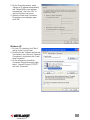
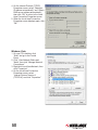
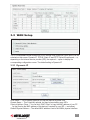
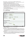
4-Port
Broadband
Router
user
manual
Model 524537
INT-524537-UM-0309-02
introduction
Thank you for purchasing the INTELLINET NETWORK SOLUTIONS™ 4-Port Broadband Router,
Model 524537.
Combining a router, firewall and four-port Fast Ethernet switch, this handy device lets you
experience fast speeds as you surf the Web, download music or photos, and play online games.
A DHCP server that automatically assigns IP addresses to users on the LAN — plus UPnP
that supports gaming — makes this the perfect router for the home network.
Of course, keeping intruders out of your network can be a challenge, but this feature-rich router
is designed to make that seemingly daunting task easier. It includes a true firewall that secures
your network against hackers. With Network Address Translation (NAT) to shield your networked
devices from intruders plus content control using URL and MAC filtering, you can rest assured
that you have taken the necessary precautions to protect the data on your network.
The easy-to-follow instructions in this user manual help make setup and operation quick and
simple, so you’ll also soon be enjoying the benefits of these additional features:
• Integrated 10/100 Mbps LAN switch with Auto MDI/MDI-X support
• Supports virtual server and DMZ (demilitarized zone)
• Supports DDNS (dynamic DNS)
• Supports VPN pass-through (PPTP, L2TP)
• Supports static routing
• DHCP server supports static lease management
• Supports remote management
• Easy installation through Web-based user interface
• Firmware updates via Web-based user interface
• Warranty
Package Contents
• 4-Port Broadband Router
• User manual
• RJ45 Ethernet cable: 1.0 m (3 ft.)
• Power adapter
NOTE: Some screen images have been modified to fit the format of this user manual.
3
table of contents
section page
1 Hardware Installation..................................................................................................... 5
1.1 Rear Panel Ports & Jacks.................................................................................... 5
1.2 Front/Top Panel LEDs.......................................................................................... 5
2 Network Settings........................................................................................................... 6
2.1 IP Address Setup................................................................................................. 6
2.2 Browser Login...................................................................................................... 9
3 Configuration............................................................................................................... 10
3.1 Status................................................................................................................. 10
3.1.1 Status........................................................................................................... 10
3.1.2 Statistics...................................................................................................... 10
3.1.3 System Log.................................................................................................. 10
3.2 WAN Setup..........................................................................................................11
3.2.1 Dynamic IP...................................................................................................11
3.2.2 PPPoE..........................................................................................................12
3.2.3 Static IP........................................................................................................12
3.2.4 PPTP.............................................................................................................13
3.3LAN Setup...........................................................................................................14
3.4 Routing................................................................................................................15
3.5 NAT......................................................................................................................15
3.5.1 DMZ Host Setup...........................................................................................15
3.5.2 FTP Private Port...........................................................................................15
3.5.3 Virtual Server Setup.................................................................................... 16
3.5.4 Port Triggering............................................................................................. 16
3.6 Firewall................................................................................................................17
3.6.1 MAC Filtering Configuration.........................................................................17
3.6.2 Connection Filtering Configuration...............................................................18
3.6.3 URL Filtering Configuration......................................................................... 19
3.7DDNS................................................................................................................. 19
3.8 Misc. Configuration............................................................................................ 19
3.8.1 Login ID & Password Setup......................................................................... 20
3.8.2 Remote Management.................................................................................. 20
3.8.3 UPnP Setup................................................................................................. 20
3.8.4 System Time Setup..................................................................................... 20
3.8.5 WAN Link Status & Setup............................................................................ 21
3.8.6 Restore Default / Restart System................................................................ 21
3.8.7 Firmware Upgrade....................................................................................... 21
4 Specifications.............................................................................................................. 22
4
1 hardware installation
Using the included RJ45 Ethernet cable (and more, as needed), make your 4-Port Broadband
Router network connections by following the steps below and referring to the Port and LED
descriptions (presented from left to right).
1.Turn off all devices to be incorporated into the network, including any PCs, switches/hubs,
the modem and the router.
2.Connect the LAN or Ethernet network port of the cable/DSL modem to the router’s WAN port.
3.Connect PCs (and any switch/hub used to expand the network) to the router’s LAN ports.
4.Turn on the cable/DSL modem, then turn on the PC you’ll be using to configure the router.
5.Connect the included power adapter to the router and an AC outlet.
1.1 Rear Panel Ports & Jacks
WAN — This 10/100Mbps RJ45 port is for the cable/DSL modem connection.
PC1-4 — These four LAN ports are where you connect networked devices, such as PCs,
print servers, remote hard drives and anything else you want to put on your network. If you
connect a LAN port to a switch or hub, check that both the device’s Power LED and the
router’s corresponding PC/LAN LED (see below) light to confirm the connection.
Default — Pushing this recessed button clears all established router configuration settings and
resets to the factory default settings. See Section 3: Restore Defaults.
Power — This is the jack for the included external 9 V DC, 700 mA power adapter.
1.2 Front/Top Panel LEDs
SYS
PC4
PC3
PC2
PC1
WAN
SYS — Lights when the router power is on.
PC1-4 — These are the LAN Link/Activity LEDs that correspond to the four port connections
on the rear panel of the router. Lighted indicates a successful connection; blinking indicates
data is being transmitted or received through that port.
WAN — Lighted indicates a successful connection; blinking indicates data is being transmitted
or received through that port.
5
2 network settings
Before you can connect to the router and begin your configuration, you need to be able to obtain
an IP address automatically; that is, establish a dynamic IP address. The IP Address Setup
procedures for Windows 98SE, Me, 2000, XP and Vista are presented here.
2.1 IP Address Setup
Windows 98SE / Me
1.On your PC’s desktop, click “Start” and go to the Control Panel.
2.Double-click the “Network” icon to display the Network dialog box.
3.Click the Configuration tab and ensure that you have the appropriate network card installed.
4. Select “TCP/IP.” NOTE: If “TCP/IP” is listed more than once, select the item that has an
arrow (→) pointing to the network card installed on your computer. Do not choose the TCP/
IP listing that has the words “Dial Up Adapter” beside it.
5.Click “Properties” to display the TCP/IP Properties dialog box.
6. Ensure “Obtain IP Address Automatically” is selected/checked.
7. In the WINS Configuration dialog box, ensure that “Disable WINS Resolution” is checked.
8. In the Gateway dialog box, remove all entries from the “Installed gateways” section by
selecting them and clicking “Remove.”
9. In the DNS Configuration dialog box, remove all entries from the DNS Server Search Order
box by selecting them and clicking “Remove.” Remove all entries from the Domain Suffix
Search Order box by selecting them and clicking “Remove.” Click “Disable DNS.”
10. Click “OK” to return to the Network Configuration dialog box.
11. Click “OK.” If prompted to restart, click “Yes.”
Windows 2000
1.On your PC’s desktop, click “Start”
and “Settings,” then go to the Control
Panel.
2.Double-click the “Network and Dial-up
Connections” icon.
3.Right-click on the “Local Area
Connections” icon to display the
pop-up menu, then click Properties.”
4.Highlight “Internet Protocol (TCP/P)”
and click “Properties” (right).
6
INTELLINET NETWORK SOLUTIONS 4-Port Broadband Router
5.On the Properties screen, select
“Obtain an IP address automatically”
and “Obtain DNS server address
automatically,” then click “OK” to
return to the previous screen.
6.When the Local Area Connection
Properties screen displays again,
click “OK.”
Windows XP
1.On your PC’s desktop, click “Start”
and go to the Control Panel.
2.Double-click the “Network and Internet
Connections” icon, then click “Network
Connections” and double-click “Local
Area Connection.”
3.On the subsequent Local Area
Connection Properties screen (right),
select “Internet Protocol (TCP/IP)”
and click “Properties.”
INTELLINET 4-Port Broadband Router
7
4.On the Internet Protocol (TCP/IP)
Properties screen, select “Obtain an
IP address automatically” and “Obtain
DNS server address automatically”;
then click “OK” to return to the Local
Area Connection Properties screen.
5. When the Local Area Connection
Properties screen displays again, click
“OK.”
Windows Vista
1.On your PC’s desktop, click
“Start” and go to the Control
Panel.
2.Click “View Network Status and
Tasks”; then click “Manage Network
Connections.”
3.Right-click Local Area Network, then
click “Properties.”
4.On the Local Area Connection
Properties screen, select
“Internet Protocol Version 4
(TCP/IPv4)” and click “Properties.”
8
INTELLINET NETWORK SOLUTIONS 4-Port Broadband Router
5.On the Internet Protocol Version 4
(TCP/IPv4) Properties screen, select
“Obtain an IP address automatically”
and “Obtain DNS server address
automatically”; then click “OK.”
2.2 Browser Login
Now that you’ve obtained an IP address, there’s just one more step before you can begin to
configure your router. As this device is configured through an Ethernet connection, it’s necessary
to confirm that the host PC is set on an IP subnetwork that can be accessed by the router.
For example, if the default network address of the router’s Ethernet interface is 192.168.2.x,
then the host PC should be set at 192.168.2.xxx (where xxx is a number between 2 and 254),
and the default subnet mask is 255.255.255.0.
1. Open your Web browser (Microsoft Internet Explorer 4.0 or Firefox 2.0 or later) and enter
the IP address (192.168.2.1) in the address bar. Press <Enter> on your keyboard to display
a login window (below).
2. Fill in the “User
Name” and the
“Password” fields,
using the default
values (“admin” for
the username;
“1234” for the
password) if this is
the first time you’re
logging in and you .haven’t changed your security settings yet (see Section 3.8.1: Login ID &
Password Setup). NOTE: For security reasons, it’s always recommended that you change
the password from the factory-set default value as soon as you can.
3. Click “OK” to display the router’s Web-based user interface homepage and begin your
configuration, as instructed in the next section.
9
3 configuration
This 4-Port Broadband Router provides a Web-browser management mode that uses the Webbased user interface presented in this section. Once you’ve logged in (Section 2.2 above), the
Configuration homepage will display, from which you can navigate through the utility as needed
to enter or change settings.
On the left-hand side of each screen is the Function Menu, which presents the eight primary
Configuration sections: Status, WAN Setup, LAN Setup, Routing, NAT, Firewall, DDNS and
Misc. When a section listed in the Function Menu is clicked, corresponding information and
options display to the right, including tabs at the top (Status, Statistics and System Log in the
Status section) that can be clicked to display these specific sub-menus. At the top-right of each
screen is the “Save” button, which is clicked whenever you want to save whatever settings
you’ve made.
3.1 Status
Once you’ve established your configuration settings, the Status screens provide information
and records you may need to make subsequent network decisions and upgrades.
3.1.1 Status
Presented above as the homepage, the Status sub-screen displays the connection status for
the router’s WAN/LAN interfaces and firmware version numbers.
Connect — Click to activate the Connect on Demand function, which connects the router to the
Internet.
3.1.2 Statistics
This screen (below) displays a record of packets sent and received on the WAN interface.
Refresh — Click any time you want to update the information. (The data automatically updates
every 5 seconds.)
3.1.3 System Log
Among other things, this screen displays unauthorized attempts to access your network.
10
3.2 WAN Setup
The 4-Port Broadband Router allows one of four Internet-LAN connection types, which can be
selected on this screen: Dynamic IP, PPPoE, Static IP and PPTP. Select the preferred — or,
depending on the Internet service provider (ISP), the required — option to display the
corresponding configuration screen. The default setting is Dynamic IP.
3.2.1 Dynamic IP
Host Name — This is typically optional, but may be required by some ISPs.
Domain Name — This is typically optional, but may be required by some ISPs.
Physical Address Clone — You can click “MAC Clone” to copy the MAC address of your PC
so that it’s also the MAC address of this device (if required by your ISP — see below).
Default Physical Address — The default MAC address is set to the WAN’s physical interface
11
MAC address on the router. It is recommended that you not change the default MAC address
unless it’s required by your ISP.
MTU — Enter a value for the largest packet size to be permitted for network transmission. The
default value of 1496 is recommended.
Primary DNS — Enter the primary address assigned by your ISP. NOTE: This is optional.
Secondary DNS — Enter the secondary address assigned by your ISP. NOTE: This is optional.
Apply — Click “Apply,” then “Save” to set and save any changes.
3.2.2 PPPoE
PPPoE Account — Enter your PPPoE username (provided by your ISP).
PPPoE Password — Enter your PPPoE password (provided by your ISP).
Physical Address Clone — You can click “MAC Clone” to copy the MAC address of your PC
so that it’s also the MAC address of this device (if required by your ISP — see below).
Default Physical Address — The default MAC address is set to the WAN’s physical interface
MAC address on the router. It is recommended that you not change the default MAC address
unless it’s required by your ISP.
MTU — Enter a value for the largest packet size to be permitted for network transmission. The
default value of 1492 is recommended.
Primary DNS — Enter the primary address assigned by your ISP. NOTE: This is optional.
Secondary DNS — Enter the secondary address assigned by your ISP. NOTE: This is optional.
Connect to Internet automatically (Default) — When this is selected, the Internet connection is
maintained as long as the router remains on. This is the default setting.
Auto disconnect when idle, time out — You can configure the router to cut your connection with
your ISP after a specified period of time (Max. Idle Time, which you enter in the text field to
the right).
Connect to Internet automatically — If you’ve been disconnected due to inactivity, select this
option to re-connect.
Apply — Click “Apply,” then “Save” to set and save any changes.
3.2.3 Static IP
WAN IP Address — Enter as directed by your Internet service provider.
Subnet Mask — Enter as directed by your Internet service provider.
Default Gateway — Enter as directed by your Internet service provider.
Primary DNS — Enter as directed by your Internet service provider.
Secondary DNS — Enter as directed by your Internet service provider
Physical Address Clone — You can click “MAC Clone” to copy the MAC address of your PC
so that it’s also the MAC address of this device (if required by your ISP).
12
Default Physical Address — The default MAC address is set to the WAN’s physical interface
MAC address on the router. It is recommended that you not change the default MAC address
unless it’s required by your ISP.
MTU — Enter a value for the largest packet size to be permitted for network transmission. The
default value of 1496 is recommended.
Apply — Click “Apply,” then “Save” to set and save any changes.
3.2.4 PPTP
User Name — Enter the PPTP username provided by your ISP.
Password — Enter the PPTP password provided by your ISP.
13
Server IP Address — Enter the PPTP server address provided by your ISP.
WAN Connection Type: The two options are “DHCP” or “Static IP.” Select “Static” if your ISP
assigned you the IP address, and enter it here.
Primary DNS — Enter as directed by your Internet service provider.
Secondary DNS — Enter as directed by your Internet service provider
Physical Address Clone — You can click “MAC Clone” to copy the MAC address of your PC
so that it’s also the MAC address of this device (if required by your ISP).
Default Physical Address — The default MAC address is set to the WAN’s physical interface
MAC address on the router. It is recommended that you not change the default MAC address
unless it’s required by your ISP.
MTU — Enter a value for the largest packet size to be permitted for network transmission. The
default value of 1496 is recommended.
Apply — Click “Apply,” then “Save” to set and save any changes.
3.3 LAN Setup
The LAN Setup screen allows you to specify a private IP address for your router’s LAN ports
as well as a subnet mask for your LAN segment.
System IP address — This is the router’s LAN port IP address (your LAN clients’ default
gateway IP addresses).
Subnet Mask — Specify a subnet mask for your LAN segment.
DHCP Server on — Select to enable or disable the DHCP server. When enabled (“on”), the
router will automatically give your LAN clients an IP address. When not enabled/selected,
you’ll need to manually set your LAN clients’ IP addresses. NOTE: Make sure the LAN client
is in the same subnet as this broadband router if you want the router to be your LAN clients’
default gateway.
DHCP IP Pool — You can select a particular IP address range for your DHCP server to issue
IP addresses to your LAN clients. NOTE: By default the IP range is from 192.168.2.100 to
192.168.2.254. If you want your PC to have a static/fixed IP address, then you’ll need to
choose an IP address outside this IP address pool.
14
DHCP Lease Time — Specify how long (in seconds) an IP address is valid for a computer
before a new IP address is issued. Normally, there is no need to change this value.
In the DHCP IP Address Reserving panel, you can reserve IPs for a specific computer.
Auto Setup — Select to assign a particular IP to your computer.
Physical Address — As an option to “Auto Setup,” enter the MAC address of the network card
installed in the computer to assign a particular IP to it and click “Add,” which will display a
Current Address Reserving Table showing information about current address reserving. To
remove a listing from the table, select it and click “Delete.”
Apply — Click “Apply,” then “Save” to set and save any changes.
3.4 Routing
If the router is connected to more than one network, it may be necessary to set up a static
route between them. A static route is a pre-determined pathway that network information must
travel in order to reach a specific host or network.
Type / Target / Mask / Gateway — Fill in these fields required by this Static Routing function.
Add — Click to add a new static routing entry and display the Current Routing Table, which
shows the valid routing paths in the router. To remove a listing from the table, select it and
click “Delete.”
Apply — Click “Apply,” then “Save” to set and save any changes.
3.5 NAT
Network Address Translation (NAT) allows multiple users at your local site to access the
Internet through a single public IP address. NAT provides firewall protection from hacker attacks
and has the flexibility to allow you to map private IP addresses to public IP addresses for key
services such as Web and FTP sites.
3.5.1 DMZ Host Setup
The DMZ screen allows one local user to be exposed to the Internet for use of a specialpurpose service such as Internet gaming and videoconferencing. DMZ hosting forwards all
the ports for one PC at the same time.
DMZ — Select to activate the function, then enter the host IP in the field to the right.
Apply — Click “Apply,” then “Save” to set and save any changes.
3.5.2 FTP Private Port
This enables a user to set up an FTP server which is not using the standard Port 21.
Port Number — Select to activate the function, then fill in the field to the right.
15
Apply — Click “Apply,” then “Save” to set and save any changes.
3.5.3 Virtual Server Setup
This screen lets you specify some services to be visible by outside users. The router can
detect an incoming service request and forward it to the specific local computer to handle it.
For example, a user can assign a PC in the LAN to act as a Web server inside and expose it
to the outside network. An outside user can browse inside the Web server directly while it is
protected by NAT.
Rule Name — Enter a description of this setting for identification.
Internal Server IP Address — This is the LAN client/host IP address that the external port
number packet will be sent to.
Protocol — Select a protocol type from the drop-down menu: TCP, UDP, FTP, HTTP, HTTPS,
POP3, SMTP, DNS, TELNET, IPSEC, PPTP.
External Port — This is the port number that is open to the outside (public) Internet.
Internal Port — This is the internal PC port (in most cases, this is identical to the external port.
Add — Click after filling in the fields to add the rule and display the Current Virtual Server Table,
which shows the valid virtual servers in the router. To remove a listing from the table, select it
and click “Delete.”
Apply — Click “Apply,” then “Save” to set and save any changes.
3.5.4 Port Triggering
This screen allows the router to watch outgoing data for specific port numbers. The IP address
of the computer that sends the matching data is remembered by the router so that when the
requested data returns through the router the data is pulled back to the proper computer by
way of IP address and port mapping rules.
Predefined Trigger Rules — Select one of the predefined rules from the drop-down menu.
Rule Name — Enter any name you want to use for identification.
Trigger Protocol — Select either “TCP” or “UDP” as the outbound port protocol.
Trigger Port — This is the out going (outbound) range of port numbers for this particular
application. NOTE: Individual port numbers are separated by a comma (e.g., 47824, 5776).
To input a port range, use a hyphen to separate the two port numbers (e.g., 3300-3800).
16
Forward Protocol — Enter the incoming (inbound) port or port range for this type of application
(e.g., 2300-2400, 47624). NOTE: Individual port numbers are separated by a comma (e.g.,
47824, 5776).
Forward Port — Select the inbound port protocol type: “TCP” or “UDP.”
Add — Click after filling in the fields to add the rule and display the Current Trigger-Port Table,
which shows the valid trigger rules in the router. To remove a listing from the table, select it
and click “Delete.”
Apply — Click “Apply,” then “Save” to set and save any changes.
3.6 Firewall
The router provides extensive firewall protection by restricting connection parameters to limit
the risk of hacker attack, and by defending against a wide array of common hacker attacks.
The router provides packet filtering rules by restricting service ports, IP addresses or MAC
addresses.
3.6.1 MAC Filtering Configuration
You can block certain client PCs from accessing the Internet based on MAC addresses.
Stop — Click to turn off the Mac Filtering configuration when “Status” shows “enabled”; click
(“Start”) to turn on the configuration when it’s shown as “disabled.”
Check Box — If selected, the undefined item in the MAC Address list is allowed to access the
Internet.
MAC Address — Enter the toggled physical address to be either allowed or denied access to
17
the Internet (by selecting “Permit” or “Deny” from the drop-down menu. NOTE: Enter the
12-digit MAC address in this format: XX-XX-XX-XX-XX-XX (with the hyphens).
Add — Click after filling in the fields to add the rule and display the Current MAC Filtering Table,
which shows the valid MAC filtering rules in the router. To remove a listing from the table,
select it and click “Delete.”
Apply — Click “Apply,” then “Save” to set and save any changes.
3.6.2 Connection Filtering Configuration
This screen lets you control a certain client PC’s access to the Internet based on IP addresses,
application types (i.e., HTTP port) and time of day.
Stop — Click to turn off the Connection Filtering configuration when “Status” shows “enabled”;
click (“Start”) to turn on the configuration when it’s shown as “disabled.”
Check Box — If selected, the undefined item in the IP Address list is allowed Internet access.
Rule Name — Enter any name you want to use for identification.
Source IP address— Enter the IP address you want to apply this Access Control rule to.
Protocol — Select the protocol type: TCP, UDP, FTP, HTTP or all of them.
Destination Port — Assign a port number or a port range. The router will block clients from
accessing Internet services that use these ports.
Days To Block — Select days to block.
Times To Block — Select times to block.
Add — Click after filling in the fields to add the rule and display the Current Access Control
Table, .which shows the current Access Control rules in the router. To remove a listing from
the table, select it and click “Delete.”
Apply — Click “Apply,” then “Save” to set and save any changes.
18
3.6.3 URL Filtering Configuration
This screen lets you enter keywords specific to the site in these fields. The router will block
access to sites that use these keywords.
Input Filtering Keyword — Enter whatever keyword you want to block access to. You can even
use asterisks and question marks, which act as “wild card” symbols: The asterisk (*) will
substitute for multiple characters; the question mark (?) will substitute for a single character.
Add — Click after filling in the field to add the rule and display the Current URL Filtering Control
Table, which shows the current rules in the router. To remove a listing from the table, select
it and click “Delete.”
Apply — Click “Apply,” then “Save” to set and save any changes.
3.7 DDNS
This feature lets you assign a fixed host and domain name to a dynamic Internet IP address,
which can be useful when you’re hosting your own Web site, FTP server or other server behind
the router. NOTE: Before you can use this feature, you need to sign up for DDNS service. (Go
to dyndns.com for options.) If you don’t want to use this feature, keep the default setting, which
is “Stop.”
User ID — Enter the username of the account you set up with DynDNS.org.
Password — Enter the password of the account you set up with DynDNS.org.
Host Name — Enter the host name of the account you set up with DynDNS.org.
Information — The status of the DDNS service connection is displayed here.
Apply — Click to finish the settings, then “Save” to set and save any changes.
Refresh — Click to display the newest status..
3.8 Misc.
This menu presents a number of options you can use to “fine tune” your configuration of the
router.
19
3.8.1 Login ID & Password Setup
The factory-set default password is “guest.” You can change the default password to ensure
that someone can’t adjust your settings without your permission. Every time you change your
password, record it and keep it in a safe place: If you forget it, you’ll need to reset the router
to the factory defaults. (See Section 1.1 regarding the “Default” button for resetting the device.)
New Password — Enter your new password.
Confirmed New Password — Enter your new password again for verification purposes.
Apply — Click “Apply,” then “Save” to set and save any changes.
3.8.2 Remote Management
This feature allows you to manage the router from a remote location via the Internet.
Management Port — Enter the port number you want to use for this feature. To access the
Web-based management from a remote site, enter http://<WAN IP Address>:8080. (e.g.,
http://192.168.1.8:8080, where 8080 is the management port number, as shown above).
Apply — Click “Apply,” then “Save” to set and save any changes.
3.8.3 UPnP Setup
Universal Plug and Play (UPnP) allows automatic discovery and configuration of equipment
attached to your LAN, ensuring compatibility with networking equipment, peripherals and
software and provided by manufacturers who incorporate the Universal Plug and Play feature.
Enable UPnP Server — In other words, just select this to use UPnP.
Apply — Click “Apply,” then “Save” to set and save any changes.
3.8.4 System Time Setup
This feature allows your router to base its time on the settings configured here (which will
affect functions such as Firewall).
GMT — Select the time zone of the country you are currently in from the drop-down menu.
The router will set its time based on your selection
Apply — Click “Apply,” then “Save” to set and save any changes.
20
3.8.5 WAN Link Status & Setup
WAN Link Setup — Select the desired mode from the drop-down menu, which will then display to the right of “WAN Link Status.” The default setting is “Auto.”
Apply — Click “Apply,” then “Save” to set and save any changes.
3.8.6 Restore Default / Restart System
Restore Default — Click to restore the router’s configuration to its factory default settings. The
router will present a confirmation message, then restart automatically.
Restart System — Click to reboot the router.
3.8.7 Firmware Upgrade
To upgrade the firmware of your router, you need to download the firmware file to your local
hard disk.
New Firmware File — Enter the firmware file name or click “Browse” to locate it on your PC.
21
4 specifications
• Firewall:
- URL filter
- MAC address filter
- Connection filtering: limits access to the
General
Internet of PCs in the LAN based on a
• LAN ports: 4 RJ45 10/100 Mbps data ports time schedule
• LAN ports with Auto MDI/MDI-X
• Supports UPnP (Universal Plug and Play)
• WAN port: 10/100 Mbps RJ45 connector
• Supports DHCP (client/server)
• Certifications: FCC Class B, CE Mark
• Supports PPPoE (DSL), DHCP (cable/DSL) .
and static IP
Router
• Supports VPN PPTP L2TP pass-through
• Supported WAN connection types:
- Dynamic IP (DHCP for cable service or LEDs
DSL)
• SYS (power)
- Static IP
• WAN Link/Act
- PPPoE/PPTP (for DSL)
• LAN 1-4 Link/Act
• Protocols:
- CSMA/CD
Environmental
- TCP/IP
• Dimensions: 150 (W) x 105 (L) x 27 (H) mm .
- UDP
(5.9 x 4.1 x 1.06 in.)
- ICMP
• Weight: 0.142 kg (0.31 lbs.)
- PPPoE
• Operating temperature: 0 – 50°C (32 – 122°F)
- NTP
• Operating humidity: 10 – 95% RH,
- NAT
non-condensing
- DHCP
• Storage temperature: -40 – 70°C (-40 – 158°F)
- DNS
Power
- DDNS
• External power adapter: 9 V DC, 700 mA
- ARP
• NAT:
Package Contents
- Virtual server
• 4-Port Broadband Router
- Special applications (port trigger)
• RJ45 Ethernet cable: 1.0 m (3 ft.)
- DMZ (demilitarized zone)
• Power adapter
• User manual
Standards
• IEEE 802.3 (10Base-T Ethernet)
• IEEE 802.3u (100Base-TX Fast Ethernet)
22
INTELLINET NETWORK SOLUTIONS™ offers a complete line
of active and passive networking products.
Ask your local computer dealer for more information or visit
www.intellinet-network.com.
Copyright © INTELLINET NETWORK SOLUTIONS
All products mentioned are trademarks or registered trademarks of their respective owners.