1
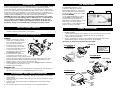
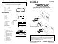
FD134030
FACTORY WIRING CODES
•
NOTE:
•
All wire codes are viewed as looking at the front of the plug with the wires
exiting the rear.
Use these wiring codes as a guide. Your vehicle might differ.
IN-DASH INSTALLATION KIT FOR
1996-99 FORD TAURUS
1996-99 MERCURY SABLE
WITH ROTARY CLIMATE CONTROLS
BLACK 14- SPEAKER INPUT *
1
2
3
4
5
6
7
=
=
=
=
=
=
=
LRLR+
RRRR+
LFLF+
RF-
8
9
10
11
12
13
14
*Located in trunk
=
=
=
=
=
=
=
RF+
Open
Power Antenna
Open
Ground
Ground
Battery +12V
1
5 6 7 8
2 3 4
12 13 14
9 10 11
1996-97 VEHICLES
GRAY PLUG 8-PIN
1
2
3
4
5
6
7
8
=
=
=
=
=
=
=
=
2
1
Illumination
Ground
Battery +12V
Open
Open
Ground
Open
Accessory +12V
4
5
3
6
7 8
BLACK 16-PIN
1
2
3
4
5
6
7
8
=
=
=
=
=
=
=
=
Led Defrost On +12V
Open
Not Used
Not Used
Not Used
Not Used
Not Used
Not Used
9
10
11
12
13
14
15
16
=
=
=
=
=
=
=
=
Open
Momentary Defrost on
Open
Open
Not Used
Open
Not Used
Not Used
Not Used = Substitute
"Not for aftermarket use"
Minor modification may be
necessary on console model.
See shaded area.
1998-UP VEHICLES
POWER AND SPEAKER
1.
2.
3.
4.
5.
6.
7.
8.
9.
10.
11.
12.
13.
14.
15.
16.
17.
18.
19.
20.
= White/Pink = Not Used
= Blue/White = Not Used
= Black = Not Used
= Green/Violet = Defroster on Indicator
= Black/Pink = +12V Accessory
= Empty
= Light Green/Black = Not Used
= Empty
= Light Blue/Black = Not Used
= Black (Larger Gauge) = -12V Chassis Ground
= Brown/Light Green = Not Used
= Gray = Not Used
= Empty
= Blue/Orange = Defroster Switch Wire
(Momentary Ground)
= Red/Yellow = Not Used
= Gray/Red = Not used
= Tan = Not Used
= Light Blue/Pink = Not Used
= Black/Light Green = Not Used
= White = +12V Constant
1
2
3
4
5
6
7
8
9
10
11 12 13 14 15 16 17 18 19
20
LIABILITY DISCLAIMER
This instruction booklet is based on carefully documented data and research of automobile dash
disassembly, wire harness/codes and information pertaining to installation of this kit (#FD134030) in
1996-99 Ford Taurus and Mercury Sable Vehicles. Scosche Industries, Inc. can not be held
responsible for discrepancies/inconsistencies that may occur due to the automobile during the
installation of components while using this booklet.
If you have any further questions, call:
©2004 SCOSCHE INDUSTRIES, INC.
4
TECH HELP: 1-800-621-3695, ext. 3
SI 4/04- FD134030(3000408)
KIT INSTALLATION:
INTRODUCTION
Thank you for purchasing the Scosche FD134030 installation panel. The FD134030 replaces
the factory radio/integrated control panel, while maintaining the original Rotary Climate
Controls and hardware. The factory radio dash panel is a control unit only, the amplifier and
tuner sections of the radio are remote located in left side of trunk on sedans, or left rear behind
the spare tire in wagons (see illustration "C"). The antenna cable is also located at the rear
module. The Scosche FD12 (18ft. speaker connector extension), FDA-18 (antenna extension),
and FD22 (FD10 to FD20 adapter) are included for aftermarket radio installations.
CAUTION: Disconnect your vehicle's negative battery terminal before the installation to help prevent electrical damage. We recommend the use of a volt/ohm meter
over a test light to check wiring. A test light or grounded wire probe can cause
damage to the vehicle's computer and/or diagnostic systems. Avoid all factory air
bag wiring - air bags can accidentally deploy causing serious injury or death.
1996-1997 MODELS
The FD134030 installation kit comes
prepared for 1996-1997 Ford Taurus/
Mercury Sable applications. Connect both
the 8 pin Radio power harness and the 16
pin defroster harness into the factory plugs.
1998-1999 MODELS
Use the supplied FD22 harness to adapt
the FD134030 for 1998-1999 models.
Connect the 8 pin power plug from the
FD22 with the corresponding plug on the kit
panel. Connect the 16 pin defroster
harness with the corresponding plug on the
kit panel. See picture to the right.
FACTORY STEREO REMOVAL
1. Insert DIN removal tools to release factory stereo/climate control panel. Unplug all
electrical connectors and vacuum lines, remove panel.
FD134030 KIT PREPARATION
CLIMATE CONTROL KNOB HOUSING
REMOVAL:
1. Align the control knobs to vertical
position, then carefully pull off three
rotary control knobs from the face of
the factory radio/control panel.
2. From the back side of the factory
control panel, extract one (1) 5mm
screw from the FAN switch, twist out
(counter clockwise) to remove.
Repeat this procedure (clockwise) for
the TEMPERATURE switch.
3. From the back side of the factory
control panel, loosen the three (3) torx
head panel retention screws located next to the
switches removed. Carefully release the tape covering the bottom edge of the control
panel (the tape will be refitted). Carefully separate bottom of panel about 1/4". Use a
small screwdriver to release vacuum control retention clips.
4. Reattach all switches to the back side of the Scosche FD134030 installation panel in the
corresponding slots using the factory screws.
5. Reattach rotary control knobs.
MOUNTING CLIPS
1. Extract one (1) T-15 torx screw holding the factory mounting clip from each side. Remove
clips and reattach to the Scosche FD134030 using the factory screws.
AFTERMARKET RADIO WIRING CONNECTION
1. Use the supplied connectors constant, ignition, dimmer, and ground wires for Aftermarket
radio installation.
2. Connect the new radio’s speaker outputs to the bare wire ends of the FD12 18 ft. speaker
extension harness.
3. Connect the new radio’s antenna lead to the standard male end of the 18 ft. antenna
extension cable.
4. Run extension cables to the rear of the vehicle to connect at the tuner/amp unit.
2
1996-97
1998-99
STEREO INSTALLATION:
1. DIN front load installation. See Illustration "A".
2. DIN ISO installation.
• Attach ISO mount brackets (left and right) to the slots on kit opening, and secure radio
chassis to brackets using hardware supplied with radio. See Illustration "B".
• Snap iso trim ring to kit opening.
3. Scosche recommends rear support on all installations, by attaching the support strap,
(supplied with the radio), to the kit top support mount. See Illustrations.
*Bend strap as illustrated for maximum mounting depth.
* REAR SUPPORT
ILLUSTRATION "A"
CAUTION:
REAR SUPPORTING THE
RADIO ADDS TO THE
INSTALLATION’S
STRUCTURAL INTEGRITY.
DIN RADIO
INSTALLATION
DIN RADIO
ILLUSTRATION "B"
RADIO MOUNT
SLEEVE
DIN ISO MOUNT
INSTALLATION
DIN RADIO
TRIM PLATE
ISO MOUNT
BRACKET
ILLUSTRATION "C"
DIN RADIO
INSTALLATION
TUNER/AMP
MODULE
FACTORY
FORD
ANTENNA
LEAD
TUNER/
AMP
OUTPUT
PLUG
ICP
CONTROL
HARNESS
3
* REAR SUPPORT