1
Motherboard User’s Guide
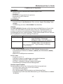
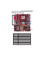
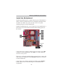
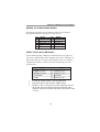
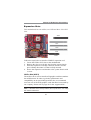
LABEL
SIR1
PCI 1-3
AUDIO2
CPUFAN
CNR1
AGP1
READ1
COMPONENTS
Infrared Port header
32-bit PCI slots
Front Panel Audio header
CPU Fan connector
Communications Networking Riser slot
AGPro slot *See page 21 for details
Card Reader Header
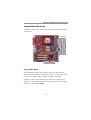
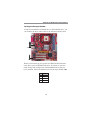
I/O Ports
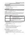
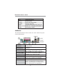
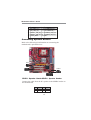
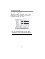
The illustration below shows a side view of the built-in I/O ports
on the motherboard.
(Optional)
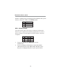
Use the upper PS/2 port to connect a PS/2
pointing device.
Use the lower PS/2 port to connect a PS/2
PS/2 Keyboard
keyboard.
Use the Parallel port to connect printers or
Parallel Port (LPT1) other parallel communications devices.
Use the COM port to connect serial devices
such as mice or fax/modems. COM1 is
Serial Port COM1
identified by the system as COM1.
Use the VGA port to connect VGA devices.
VGA Port
LAN Port (optional) Connect an RJ-45 jack to the LAN port to
connect your computer to the Network.
Use the USB ports to connect USB devices.
USB Ports
Use the three audio ports to connect audio
Audio Ports
devices. The first jack is for stereo Line-In
signal. The second jack is for stereo Line-Out
signal. The third jack is for Microphone.
PS/2 Mouse
8