1
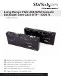
Long Range VGA USB KVM Console
Extender over Cat5 UTP - 1000 ft
SV565UTPUL
*actual product may vary from photos
DE: Bedienungsanleitung - de.startech.com
FR: Guide de l'utilisateur - fr.startech.com
ES: Guía del usuario - es.startech.com
IT: Guida per l'uso - it.startech.com
NL: Gebruiksaanwijzing - nl.startech.com
PT: Guia do usuário - pt.startech.com
For the most up-to-date information, please visit: www.startech.com
Manual Revision: 07/13/2012
FCC Compliance Statement
This equipment has been tested and found to comply with the limits for a Class B digital
device, pursuant to part 15 of the FCC Rules. These limits are designed to provide reasonable
protection against harmful interference in a residential installation. This equipment generates,
uses and can radiate radio frequency energy and, if not installed and used in accordance with
the instructions, may cause harmful interference to radio communications. However, there
is no guarantee that interference will not occur in a particular installation. If this equipment
does cause harmful interference to radio or television reception, which can be determined by
turning the equipment off and on, the user is encouraged to try to correct the interference by
one or more of the following measures:
• Reorient or relocate the receiving antenna.
• Increase the separation between the equipment and receiver.
• Connect the equipment into an outlet on a circuit different from that to which the receiver
is connected.
• Consult the dealer or an experienced radio/TV technician for help.
Use of Trademarks, Registered Trademarks, and other Protected Names and Symbols
This manual may make reference to trademarks, registered trademarks, and other
protected names and/or symbols of third-party companies not related in any way to
StarTech.com. Where they occur these references are for illustrative purposes only and do not
represent an endorsement of a product or service by StarTech.com, or an endorsement of the
product(s) to which this manual applies by the third-party company in question. Regardless
of any direct acknowledgement elsewhere in the body of this document, StarTech.com hereby
acknowledges that all trademarks, registered trademarks, service marks, and other protected
names and/or symbols contained in this manual and related documents are the property of
their respective holders.
Instruction Manual
Table of Contents
Introduction ............................................................................................1
Features......................................................................................................................................................... 1
System Requirements............................................................................................................................... 1
Package Contents...................................................................................................................................... 2
Connecting Your KVM Extender............................................................3
Preparing Your Site.................................................................................................................................... 3
Installing the Remote Unit...................................................................................................................... 5
Mask Hotkey Switch.................................................................................................................................. 5
Video Calibration (Remote Unit only) .................................................6
Using the KVM Extender........................................................................8
Using the Host Unit................................................................................................................................... 8
Keyboard Shortcut Command Sequences........................................................................................ 9
Beep Codes................................................................................................................................................... 11
LED Indicators............................................................................................................................................. 12
Alternative Hot-Key Control................................................................................................................... 14
Command Sequence - Host Unit.......................................................................................................... 14
Specifications...........................................................................................15
RJ-45 Connector Pinout........................................................................................................................... 15
Technical Support...................................................................................16
Warranty Information.............................................................................16
Instruction Manual
i
Introduction
Thank you for purchasing a StarTech.com KVM extender. This product allows a
computer to control a host system from a remote location at a distance of up to 984
feet (300 meters). For ease of installation, this product uses standard Category 5, 5E, or
6 network cabling that fits easily into almost any existing network infrastructure. For
added versatility, the KVM extender supports either PS/2 or USB computer interfaces.
Console support is provided using standard USB and VGA connectors.
Features
• Can be used with a single computer or connected to an existing KVM switch
• Easy installation using industry-standard UTP network cable
• Intuitive hotkey commands
• Supports auto-switching between host and remote users or dedicated control
• USB computers are supported at the host and remote locations (USB keyboard and
mouse required for remote console)
System Requirements
• 1 x StarTech.com integrated KVM cable for each, the host (included) and remote
(optional) computer connections. If necessary, longer cables are available,
StarTech.com ID: SVECONx (PS/2), SVECONUSx (USB)
• Unshielded Category 5/5e/6 twisted pair (UTP) straight-through network cable
terminated at each end with RJ-45 connectors (if using surface cabling)
OR
Unshielded Category 5/5e/6 twisted pair (UTP) straight-through network cable
terminated at each end in a wall-mounted outlet, with a standard Category 5/5e/6
patchcable, at both locations (if using premises cabling)
NOTE: The total length of cable between the Host and Remote Units cannot exceed
984 feet (300 meters), including patch cables (if used). Category 5e and 6 cabling is
compatible with this product and may improve performance.
NOTE: Long cable lengths between the Host and Remote Units may adversely affect
image quality at high resolutions and refresh rates. If you need to run your remote
displays at high resolutions and frequencies, use as little cabling between locations as
possible and avoid practices such as “coiling” unused cable in a ceiling.
Instruction Manual
1
This product will also control a KVM switch, allowing you to manage more than one
computer remotely. In this configuration, you can connect the KVM extender’s Host Unit
to the “console” ports on the KVM. You must use the provided power adapters if using this
configuration. You should set the Host Unit to Compatibility Mode before connecting it to
a KVM that uses the [Ctrl] key as its hotkey sequence; see page 7 for details.
Package Contents
• 1 x Host Unit
• 1 x Remote Unit
• 1 x Instruction Manual
• 1 x Power adapter
• 2 x 6 ft. 2-in-1 USB VGA KVM cable
• 2 x Set of rubber mounting feet
Instruction Manual
2
Connecting Your KVM Extender
Preparing Your Site
Before you can install the product, you need to prepare your site.
1. Determine where the Host computer will be located and set up the computer.
2. Determine where the console devices (mouse, keyboard, monitor) will be located
and place them appropriately.
3. a) If you are using surface cabling, ensure you have enough Category 5 unshielded
twisted pair (UTP) network cabling to connect the Host Unit to the Remote Unit’s
location, and that each end is terminated with a RJ-45 connector. The cabling should
not go through any networking equipment (i.e. router, switch).
OR
b) If you are using premises cabling, ensure that the Category 5 unshielded twisted
pair (UTP) network cabling between the Host Unit and the Remote Unit has been
properly terminated in a wall outlet in each location and there is a patch cable long
enough to connect the Remote Unit and the Host Unit to their respective outlets.
The cabling should not go through any networking equipment (i.e. router, switch).
Instruction Manual
3
Installing the Host Unit
1. Place the Host Unit near the Host computer system.
2. Switch off the computer and disconnect any connected devices.
3. Using the provided StarTech.com integrated KVM cable, connect the end of the cable
that has two (USB) or three (PS/2 + VGA) connectors to the VGA Out connector and the
USB or mouse and keyboard PS/2 connectors on the Host computer as appropriate.
(The PS/2 version of the cable is color-coded). Connect the opposite end of the cable
with a single connector to the gray-coded connector marked COMPUTER on the Host
Unit of the KVM extender.
4. If you wish to have local console access to the host computer, connect a USB mouse,
keyboard, and VGA monitor to the indicators marked as CONSOLE on the Host Unit.
5. Connect the UTP cable connection for the Remote Unit to the NETWORK RJ-45
connector on the Host Unit. Connect the opposite end to a terminated wall outlet
(if you are using premises cabling) or run it directly to the Remote Unit.
NOTE: The Host Unit can draw power from the Host computer system. If it cannot
draw sufficient power from the Host computer, however, a power adapter (not
included) may be required.
Instruction Manual
4
Installing the Remote Unit
1. Place the Remote Unit near the remote keyboard/mouse/monitor setup.
2. Connect the USB mouse, keyboard, and a VGA monitor to the indicators marked as
CONSOLE on the Remote Unit.
OPTIONAL: If connecting a computer system directly to the Remote Unit, switch
off the computer and disconnect any existing VGA and input connections. Using a
StarTech.com integrated KVM cable, connect the end of the cable that has two (USB) or
three (PS/2) connectors to the VGA Out connector and the USB or mouse and keyboard
PS/2 connectors on the computer as appropriate. (The PS/2 version of the cable is
color-coded.) Connect the opposite end of the cable with a single connector to the
gray-coded connector marked COMPUTER on the Remote Unit of the KVM extender.
3. Connect the UTP cable connection for Remote Unit to the NETWORK RJ-45
connector on the Remote Unit. Connect the opposite end to a terminated wall
outlet (if using premises cabling).
4. Connect the power adapter from an electrical outlet to the Remote Unit.
WARNING! The UTP network cables that connect the Host and Remote Units carry
electrical current and should not be plugged in to other devices, as they may cause
damage. We strongly recommend marking the cables you are using with this product
at both locations for easy identification.
Mask Hotkey Switch
The Mask Hotkey switch on the rear panel of both the Host and Remote Units is a
feature for use when a KVM switch is being used. Setting the switch to ON or OFF will
Mask (disable) the units built in hotkey detection, allowing the controls keys to be sent
directly to the KVM switch.
OFF
Instruction Manual
ON
5
Video Calibration (Remote Unit only)
Video Calibration allows the user to adjust the equalization, gain and RGB skew on
the Remote Unit to optimize video performance based on the length of the UTP cable
being used, as well as other factors that may affect the signal.
There are 16 levels of coarse tuning and up to 128/256 scales of fine tuning available for
adjustment of the equalizer and gain. Skew adjustment for red, green and blue colour
channels come in 8 levels of coarse adjustment and 16/32 scales of fine adjustment.
NOTE: Video Calibration is only available when the UTP cable is connected and the
Remote unit has control of the Host computer system.
To enter Video Calibration Mode:
left [CTRL] - left [CTRL] - [F11]
To enter Video Calibration Mode while in Compatibility Mode:
left [CTRL] - left [CTRL] - [E] - [F11]
When in Video Calibration mode, the Num Lock and Scroll Lock LEDs on the keyboard
will flash simultaneously. Video calibration can now be performed. Refer to the table
for the different adjustment options.
Before Video Calibration
After Video Calibration
Instruction Manual
6
Hotkey
Description
Equalizer Adjustment (Sharpness):
Num Lock and Caps Lock LEDs will flash.
Press the left or right arrow keys for coarse tuning.
[E]
Press and hold [SHIFT] and use the left and right arrow keys for
fine tuning.
Gain Adjustment (Brightness):
Caps Lock and Scroll Lock LEDs will flash.
Press the up or down arrow keys for coarse tuning.
Press and hold [SHIFT] and use the up or down arrow keys for
fine tuning.
Red Skew Adjustment:
Num Lock LED will flash.
[R]
Press the left or right arrow keys for coarse tuning.
Press and hold [SHIFT] and use the left and right arrow keys for
fine tuning.
Green Skew Adjustment:
Caps Lock LED will flash.
[G]
Press the left and right arrow keys for coarse tuning.
Press and hold [SHIFT] and use the left and right arrow keys for
fine tuning.
Blue Skew Adjustment:
Scroll Lock LED will flash.
[B]
Press the left and right arrow keys for coarse tuning.
Press and hold [SHIFT] and use the left and right arrow keys for
fine tuning.
[ESC]
Instruction Manual
Exit Video Calibration mode. There is also a 30 sec. timeout based
on keyboard input.
7
Using the KVM Extender
This section details how to use your KVM extender at both the host and remote locations.
Using the Host Unit
The Host Unit allows users connected to the Host and Remote units to share control of
devices (hosts, computers, KVM Switches) connected to it.
The Host Unit has three modes that control which user may access the system at a
given time: Auto (the KVM extender looks for keyboard or mouse activity from both
A and B and automatically accepts input from the active console), Local (only the
user seated at the Host unit can access the system), and Remote (only the user at the
Remote station can access the system).
You can use either keyboard shortcuts (if there is a keyboard and mouse attached)
or the mode switch on the top of the Host Unit to control which user has access to
devices connected to the Host unit, by pressing the button in sequence.
By default, the Host Unit operates in Auto mode, and switches to the next mode in the
sequence each time the switch is pressed as follows:
Auto
Local
Remote
Having a keyboard and mouse attached to the console ports on the Host Unit is
recommended, since it offers access to a number of extended features.
LED Indicators
Mode
A Indicator
B Indicator
Auto (Auto senses activity)
Flashing
Flashing
Local (User at Local Unit has exclusive control)
On (solid)
Off
Remote (User at Remote Unit has exclusive
control)
Off
On (solid)
Instruction Manual
8
Keyboard Shortcut Command Sequences
Standard Command
With Compatibility
Mode Enabled
[Ctrl] - [Ctrl] - [T]
[Ctrl] - [Ctrl] - [T]
Toggles control of Computer
A between Auto, Local, and
Remote modes
[Ctrl] - [Ctrl] - [Esc]
[Ctrl] - [Ctrl] - [Esc]
Cancels the hotkey sequence
[Ctrl] - [Ctrl] [Alt]+[E]
[Ctrl] - [Ctrl] - [Alt]+[E]
Enables (2 beeps) or disables
(1 beep) Compatibility Mode
so that the KVM extender will
work with a KVM switch that
also uses a [Ctrl]
hotkey sequence
[Ctrl] - [Ctrl] [Alt]+[S]
[Ctrl] - [Ctrl] - [Alt]+[S]
Reset Host Unit to the
factory default
[Ctrl] - [Ctrl] - [1]
[Ctrl] - [Ctrl] - [E] - [1]
Local Mode: Allows the user
at Host Unit exclusive access
to Computer A; remote access
from Remote Unit is disabled
[Ctrl] - [Ctrl] - [2]
[Ctrl] - [Ctrl] - [E] - [2]
Remote Mode: Allows the
console at Remote Unit
exclusive access to Computer
A; access to the computer
from the Host Unit is disabled
[Ctrl] - [Ctrl] - [3]
[Ctrl] - [Ctrl] - [E] - [3]
Auto Mode: Wait for
keyboard console activity
[Ctrl] - [Ctrl] - [F3]
[Ctrl] - [Ctrl] - [E] - [F3]
Sets the interval of inactivity
in seconds that the Host Unit
will wait before returning to
Auto Mode
Instruction Manual
9
Description
Standard Command
With Compatibility
Mode Enabled
Description
Privacy Setting:
A. Host Unit in Local mode
( LED B: Off, LED A: On)
1 beep: Reset to Factory Default.
2/3 beeps: Disable the Local
Unit output video signal.
B. Host Unit in Auto mode
( LED A&B flashes alternately)
[Ctrl] - [Ctrl] - [F6]
[Ctrl] - [Ctrl] - [E] - [F6]
1 beep: Reset to Factory Default.
2 beeps: Upon keyboard/mouse
activation, disables the Local
Unit video output temporarily.
(Set for 5,15,30 or 60 second
interval)
3 beeps: Upon keyboard/mouse
activation the Remote Unit or
Local Unit users can disable the
output video signal temporarily.
(The user can protect their
privacy for 5,15,30,60 seconds)
[Ctrl] - [Ctrl] - [V] - 4
digit code
[Ctrl] - [Ctrl] - [E] - [V] - 4
digit code
Set the maximum video
resolution (requires
computer restart) for both
Remote and Host units.
See page 11 for codes.
Instruction Manual
10
Beep Codes
Some of the keyboard command sequences you issue to the Host Unit have multiple possible
settings. The unit will beep to indicate what setting you have selected for the command you
issued. (A short beep followed by a long beep indicates an invalid command.)
[Ctrl] - [Ctrl] - [Alt]+[E] (Compatibility Mode)
1 beep: disabled
2 beeps: enabled
[Ctrl] - [Ctrl] - [F3] (Inactivity Interval for Auto Mode)
1 beep: 5 seconds
2 beeps: 15 seconds
3 beeps: 30 seconds
4 beeps: 60 seconds
NOTE: Commands described in the [Key] - [Key] format are keys that must be pressed in
order on the keyboard. Commands described in the [Key]+[Key] format must be
pressed simultaneously.
NOTE: If the Num Lock, Caps Lock, and Scroll Lock lights are flashing in unison on the
keyboard, the other Unit has control of Computer A. You will not be able to use the computer
or issue commands until the other unit has finished using the computer.
As EDID display information is not passed through the extender to the computer, manually
setting the maximum display resolution on the extender may be necessary for content to
display correctly on the connected monitors.
4-Digit Code
Resolution
4-Digit Code
Resolution
1007
1024x768
1612
1600x1200
1208
1280x800
1610
1680x1050
1210
1280x1024
1910
1920x1080
1307
1360x768
1912
1920x1440
1409
1440x900
1914
1920x1440
1410
1440x1050
2011
2048x1152
1609
1600x900
Instruction Manual
11
Using the Remote Unit
The Remote Unit allows a user at the Remote Unit to assume control of devices
connected to the Host Unit, if the Host Unit is set to Auto or Remote mode, and it also
permits the user seated at the Remote Unit to use any connected system as though the
KVM Extender was transparent.
You can use either keyboard shortcuts or the mode switch on the top of the Remote
Unit to alternate control between A and B. Unlike the Host Unit, however, the switch
on top of the Remote unit only offers two selectable modes:
Local
Remote
LED Indicators
Mode
A Indicator
B Indicator
Remote Access (Computer A)
On (solid)
Off
Local Access (Computer B)
Off
On (solid)
Keyboard Shortcut Command Sequences
Standard Command
With Compatibility
Mode Enabled
[Ctrl] - [Ctrl] - [T]
[Ctrl] - [Ctrl] - [T]
[Ctrl] - [Ctrl] - [Esc]
[Ctrl] - [Ctrl] - [Esc]
Cancels the hotkey sequence
[Ctrl] - [Ctrl] [Alt]+[E]
[Ctrl] - [Ctrl] - [Alt]+[E]
Enables (2 beeps) or disables
(1 beep) Compatibility Mode
so that the KVM extender will
work with a KVM switch that
also uses a [Ctrl]
hotkey sequence
[Ctrl] - [Ctrl] [Alt]+[S]
[Ctrl] - [Ctrl] - [Alt]+[S]
Reset Remote Unit to the
factory default
[Ctrl] - [Ctrl] - [1]
[Ctrl] - [Ctrl] - [E] - [1]
Switches control to Computer B
Instruction Manual
12
Description
Toggles console control
between Computer A and
Computer B
Standard Command
With Compatibility
Mode Enabled
Description
[Ctrl] - [Ctrl] - [2]
[Ctrl] - [Ctrl] - [E] - [2]
Switches control to Computer A
(input allowed only if the Host
Unit is in Remote or
Auto mode)
[Ctrl] - [Ctrl] - [F2]
[Ctrl] - [Ctrl] - [E] - [F2]
Toggles console control
between Computer A and
Computer B
[Ctrl] - [Ctrl] - [F11]
[Ctrl] - [Ctrl] - [E] - [F11]
Video Calibration Entrance See
more on Video
Calibration section
[Ctrl] - [Ctrl] - [V] - 4
digit code
[Ctrl] - [Ctrl] - [V] - 4
digit code
Set the maximum video
resolution (requires computer
restart) for both Remote and
Host units.
See page 11 for codes.
Beep Codes
Some of the keyboard command sequences you issue to the Remote Unit have
multiple possible settings. The Unit will beep to indicate what setting you have
selected for the command you issued. (A short beep followed by a long beep indicates
an invalid command.)
[Ctrl] - [Ctrl] - [Alt]+[E] (Compatibility Mode)
1 beep: disabled
2 beeps: enabled
Note: Commands described in the [Key] - [Key] format are keys that must be pressed
in order on the keyboard. Commands described in the [Key]+[Key] format must be
pressed simultaneously.
Note: If the Num Lock, Caps Lock, and Scroll Lock lights are flashing in unison on the
keyboard, the other Unit has control of Computer A. You will not be able to use A until
the other Unit releases access to that computer.
Instruction Manual
13
Alternative Hot-Key Control
Instead of using the keyboard leading hot-key sequence, [Ctrl] - [Ctrl], the “Selection”
button on the Host or Remote units can be used. These commands can be used
regardless if the “Mask Hotkey” feature is enabled.
Command Sequence - Host Unit
Hot-Key
Description
[press + hold Selection button for
2 sec] - [F3]
Sets the interval of inactivity in seconds
that the Host Unit will wait before
returning to Auto Mode
[press + hold Selection button for
2 sec] - [F6]
Change video Privacy Settings.
[press + hold Selection button for
2 sec] - [V] - 4 digit code
Set maximum video resolution for
both Remote/Host units.
Command Sequence - Remote Unit
Hot-Key
Description
[press + hold Selection button for
2 sec] - [F11]
Enter Video Calibration mode.
[press + hold Selection button for
2 sec] - [V] - 4 digit code
Set maximum video resolution for
both Remote/Host units.
NOTE: Before entering Video Calibration mode, please make sure that the Host and
Remote Units are properly connected using Cat5/5e/6 UTP cabling and the Remote
Unit is in Remote mode (‘Remote’ LED flashing, ‘Local’ LED off ).
Instruction Manual
14
Specifications
Maximum Resolution
1600x1200/1920x1200 (at maximum UTP cable length)
Maximum Range
948 feet (300 meters)
Network Cabling
Type
Straight-through Unshielded Twisted Pair (UTP)
Cat. 5/5e/6
Each, Host and Remote Unit
1 x DE-15 VGA female
1 x DE-15 “Computer” female
Connectors
1 x RJ-45 Ethernet female
2 x USB type A female (for keyboard/mouse only)
1 x DC Power
Power Adapter
9~12VDC, 600mA, center positive
RJ-45 Connector Pinout
Pair 3
Pair 2
Instruction Manual
Pair 1
Pair 4
Pin
Wire
Color
Pair
Function
1
White/
Orange
2
T
2
Orange
2
R
3
White/
Green
3
T
4
Blue
1
R
5
White/
Blue
1
T
6
Green
3
R
7
White/
Brown
4
T
8
Brown
4
R
15
Technical Support
StarTech.com’s lifetime technical support is an integral part of our commitment to
provide industry-leading solutions. If you ever need help with your product, visit
www.startech.com/support and access our comprehensive selection of online tools,
documentation, and downloads.
For the latest drivers/software, please visit www.startech.com/downloads
Warranty Information
This product is backed by a three year warranty.
In addition, StarTech.com warrants its products against defects in materials
and workmanship for the periods noted, following the initial date of purchase.
During this period, the products may be returned for repair, or replacement with
equivalent products at our discretion. The warranty covers parts and labor costs only.
StarTech.com does not warrant its products from defects or damages arising from
misuse, abuse, alteration, or normal wear and tear.
Limitation of Liability
In no event shall the liability of StarTech.com Ltd. and StarTech.com USA LLP (or their
officers, directors, employees or agents) for any damages (whether direct or indirect,
special, punitive, incidental, consequential, or otherwise), loss of profits, loss of business,
or any pecuniary loss, arising out of or related to the use of the product exceed the
actual price paid for the product. Some states do not allow the exclusion or limitation
of incidental or consequential damages. If such laws apply, the limitations or exclusions
contained in this statement may not apply to you.
Instruction Manual
16
Hard-to-find made easy. At StarTech.com, that isn’t a slogan. It’s a promise.
StarTech.com is your one-stop source for every connectivity part you need. From
the latest technology to legacy products — and all the parts that bridge the old and
new — we can help you find the parts that connect your solutions.
We make it easy to locate the parts, and we quickly deliver them wherever they need
to go. Just talk to one of our tech advisors or visit our website. You’ll be connected to
the products you need in no time.
Visit www.startech.com for complete information on all StarTech.com products and
to access exclusive resources and time-saving tools.
StarTech.com is an ISO 9001 Registered manufacturer of connectivity and technology
parts. StarTech.com was founded in 1985 and has operations in the United States,
Canada, the United Kingdom and Taiwan servicing a worldwide market.