1
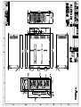
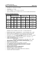
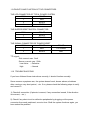
1.1 INTRODUCTION
First of all, thank you for purchasing MX3 series 2+1 mini redundant power supply.
The MX3 series is a 2+1 hot-swappable / hot-pluggable redundant power supply. It
consists of,
1) complete metal frame
2) compact size power module
3) backplane
It is composed of 2+1 pieces power modules. The number 2+1 stands for there is an
extra power module to backup the system if any power module fails.
The power module is in compact size, and built-in a 40mm ball bearing DC fan.
Particularly, a 80mm DC fan is built unto the rear side of the power system to offer
better ventilation and reliability (not available for MX3 series). Each power module is
designed with 6 outputs (+3.3V, +5V, +12V, -5V, -12V, and +5Vsb) circuits, and
compliant to ATX12V / EPS12V. All you can see on the backplane is just passive
components and this is the key point for longer MTBF.
The MR3 series offer a warning sub-system, including LED display, buzzer alarm, TTL
signal, and I2C interface device (optional). It guides user the fast way to find out the
power supply status.
When all the power modules operate normally, it balances the load share through its
parallel design, which increases the reliability of power system.
To really discover the power system and ease in using it, we recommend you to read
through this manual carefully.
1.2 PACKING
Your MX3 series should consist of the following,
a) MX3 series x 1
b) Accessory pack x 1
c) Product Manual x 1
1.3 MODEL DESINGATION
Model number identification
MX3 – 6550P / 6600P
MX3
--6
550 / 600
P
2+1 mini redundant power supply, AC input
--- 6 output channel (+3.3V, +5V, +12V, -5V, -12V & +5Vsb)
--- total output power (unit: watts)
--- built-in PFC (full range)
1.4 FEATURES
MX3 series, 550W / 600W, 2+1 redundant power supply with active PFC, complaint to
ATX12V / EPS12V
l True redundant design (passive packplane)
l N+1 power system design
l All circuit designed into the power module
l Hot-swap and hot-plug ability
l Full range (90VAC – 264VAC) operation
l Active Power Factor Correction (PFC) built-in
l Balance load sharing design
l Remote sensing design
l Meet FCC, CISPR EMI regulation
l Faulty free- slide rail design
l Smart I2C interface design (optional)
l Dual EMI line filter inlets design
l Designed with one 40mm ball bearing DC fan on power module
l An 80mm ball bearing DC fan on the rear side of power system (not available for
MX3 series)
1.5 DRAWING
1.6 SPECIFICATION
INPUT CHARACTERISTICS:
MX3-5750P
l
VOLTAGE: 90 ~ 264 VAC FULL RANGE
l
FREQUENCY : 47 ~ 63 Hz
l
INPUT CURRENT: 13 / 6.5 A FOR 115 / 230 VAC
l
INRUSH CURRENT: 80A / 100A MAX. FOR 115 / 230 VAC PER POWER MODULE
OUTPUT CHARACTERISTICS:
OUTPUT
VOLTAGE
OUTPUT CURRENT
MIN.[A] MAX.[A] PEAK(A)
REGULATION
OUTPUT
LOAD
LINE
RIPPLE & NOISE
MAX. [P-P]
5V
3.0
52
± 5%
± 1%
50mV
12V
2
56
± 5%
± 1%
120mV
-12V
0.1
1
± 10%
± 1%
120mV
3.3V
1.0
40
± 5%
± 1%
50mV
+5VSB
0.1
2.5
± 5%
± 1%
50mV
REMARKS: TOTAL CURRENT OF +5V AND + 3.3V NOT EXCEED 80 A
.
l
l
l
l
l
.
l
l
l
l
l
l
l
l
l
l
l
TEMPERATURE RANGE : OPERATING 00C --- 400C, STORAGE –200C --- 800C
HOLD UP TIME: 16 ms MINIMUM AT FULL LOAD & 90 VAC INPUT VOLTAGE
DIELECTRIC WITHSTAND: INPUT / OUTPUT 3000 VAC FOR 1 MINUTE
INPUT TO FRAME GROUND 1500 VAC FOR 1 MINUTE
EFFICIENCY: 63% TYPICAL, AT FULL LOAD
POWER GOOD SIGNAL: ON DELAY 100 ms TO 500 ms, OFF DELAY 1 ms
OVER LOAD PROTECTION: 110 ~ 160% MAX.
OVER VOLTAGE PROTECTION:
+5V à 5.7V ~ 6.7V, 3.3V à 3.7 ~ 4.7V, 12V à 13.0 ~ 15.0V
EMI NOISE INLET FILTER: FCC CLASS B, CISPR22 CLASS B
SAFETY: MEET UL 60950, CSA 22.2 60950, TÜV EN-60950,CB IEC60950
REMOTE ON / OFF CONTROL
FAULTY ALERT METHODS : LED, BUZZER, TTL SIGNAL
HOT-SWAPPABLE / HOT-PLUGGABLE REDUNDANCY FUNCTION
2 + 1 BALANCE LOAD SHARING DESIGN ON 5/12/3.3V CHANNEL
REMOTE SENSING DESIGN
ISOLATION: BUILT-IN IN THE POWER MODULE
MEET IEC-1000-3-2 CLASS D ( ACTIVE PFC )
DIMENSION: 84(H) X 150(W) X 265 (D) mm
COOLING : THREE 40 mm DC FANS ( ONE IN EACH MODULE )
AC INLET BUILT IN EACH MODULE
INPUT CHARACTERISTICS:
MX3-6550/6600P
l
VOLTAGE: 90 ~ 264 VAC FULL RANGE
l
FREQUENCY: 47 ~ 63 Hz
l
INPUT CURRENT: 9.0 / 5 A FOR 115 / 230 VAC
l
INRUSH CURRENT: 80A / 100A MAX. FOR 115 / 230 VAC PER POWER MODULE
OUTPUT CHARACTERISTICS:
OUTPUT
VOLTAGE
OUTPUT CURRENT
MIN.[A] MAX.[A] PEAK(A)
REGULATION
OUTPUT
LOAD
LINE
RIPPLE & NOISE
MAX. [P-P]
5V
3.0
60
± 5%
± 1%
50mV
12V
2
40
± 5%
± 1%
120mV
-5V
0.1
1
± 10%
± 1%
120mV
-12V
0.1
1
± 10%
± 1%
120mV
3.3V
1.0
36
± 5%
± 1%
50mV
+5VSB
0.1
2.5
± 5%
± 1%
50mV
REMARKS: TOTAL CURRENT OF +5V AND + 3.3V NOT EXCEED 70 A
TOTAL +5V AND 3.3V AND 12V POWER NOT EXCEED 520 / 570 W
.
l
l
l
l
l
.
l
l
l
l
l
l
l
l
l
l
l
TEMPERATURE RANGE : OPERATING 00C --- 400C, STORAGE –200C --- 800C
HOLD UP TIME: 16 ms MINIMUM AT FULL LOAD & 90 VAC INPUT VOLTAGE
DIELECTRIC WITHSTAND: INPUT / OUTPUT 1500 VAC FOR 1 MINUTE
INPUT TO FRAME GROUND 1500 VAC FOR 1 MINUTE
EFFICIENCY: 63% TYPICAL, AT FULL LOAD
POWER GOOD SIGNAL: ON DELAY 100 ms TO 500 ms, OFF DELAY 1 ms
OVER POWER PROTECTION: 110 ~ 160% MAX.
OVER VOLTAGE PROTECTION:
+5V à 5.7V ~ 6.7V, 3.3V à 3.7 ~ 4.7V, 12V à 13.0 ~ 15.0V
EMI NOISE INLET FILTER: FCC CLASS B, CISPR22 CLASS B
SAFETY: MEET UL 1950, CSA 22.2 NO/ 950, TÜV IEC 950
REMOTE ON / OFF CONTROL
FAULTY ALERT METHODS : LED, BUZZER, TTL SIGNAL
HOT-SWAPPABLE / HOT-PLUGGABLE REDUNDANCY FUNCTION
2 + 1 BALANCE LOAD SHARING DESIGN ON 5/12/3.3V CHANNEL
REMOTE SENSING DESIGN
ISOLATION: BUILT-IN IN THE POWER MODULE
MEET EN61000-3-2 CLASS D ( ACTIVE PFC )
DIMENSION: 82(H) X 150(W) X 254 (D) mm
COOLING : THREE 40 mm DC FANS ( ONE IN EACH MODULE )
AC INLET BUILT IN EACH MODULE
1.7 INSTALLATION & TESTING
Mount the power supply into the system chassis by using proper mounting tool. The
mounting holes of the power supply should match up with those in the chassis.
Connect the power connectors to the M/B by following the M/B instruction. There is
various on connectors / pinouts in both power supply and M/B. Please ensure to
connect the matched one; otherwise, it will cause unexpected harms.
Connect the remaining power connectors to the various peripherals as needed. These
connectors are “keyed”, so there will be only one possible way to connect them.
Before applying power source to the system, make sure these is no loosed or
incorrect connectors. Double check if all connection to the M/B is matched properly.
Maybe you would like to test the redundancy function before you put back the cover of
your system chassis, then, please power it on. If the power system operates normally,
the individual LEDs on power module and the external warning LED light in GREEN.
Now, remove one power module from the power system, the warning buzzer in the
power system will sound, the external warning LED, which displays the status of the
total power system, will become blinking, the individual LED indicating the power
module’s status will distinguish. Meanwhile, the power system will continue to backup
the power output without affecting the operation of your computing system.
The warming buzzer will sound continuously. You can reset warning buzzer by
pressing the buzzer reset switch. Insert the power module which is removed for test
earlier. The sound of the warning buzzer will stop; the external warning LED will turn
to be GREEN again; the LED indicating the status of power module will light in
GREEN. Test another power supply by performing the same procedure.
If everything works out fine, then turn off the power system. Now put back the cover of
the chassis and tighten with the screws which you have retained earlier. Now you
have completed the installation of MR3 series redundant power supply.
1.8 Hot-swap procedures
Please refer to the following when either power module is defective.
1) Locate the defective power module by examining the individual LED (if LED is
distinguished, it indicates the power module is defective).
*** WARNING:
Please perform the following step carefully; otherwise, it may cause the whole system
shutdown.
*** WARNING:
Please do not remove the defective power module until you have worn gloves to keep
from been burned. This is due to the cover of the power module is used as heat sink
for cooling. Usually, its temperature is around 50-60 degree Celsius under full load
condition.
2) Loose the screws of power module bracket.
3) Plug out the defective power module.
*** WATNING:
Please put aside the power module to wait for cooling down. Keep other people from
toughing it until it is cooled.
4) Replace a new / GOOD power module. Insert the power module into the power
system till to the end.
5) Check the LED of the power module, which should be in GREEN.
6) Check the warning LED indicating the status of total power system, which should
be in GREEN.
7) Tighten the screws of the power module.
8) If you want to test this new power module and simulate the defective situation,
please refer to Section 1.7 Installation & Testing.
Remarks: If the DC fan of the power module fails, you have to replace the power
module. Please follow the Hot-Swap Procedures for replacement.
1.9 PINOUTS AND FUNCTION OF THE CONNECTORS
THE LED CONNECTOR OF TOTAL POWER SYSTEM
PIN#
1
COLOR
RED
2
BLACK
3
GREEN
THE BUZZER RESET SWITCH CONNECTOR
PIN#
COLOR
1
2
BLACK
YELLOW
THE SIGNAL CONNECTOR OF POWER RESET
PIN#
COLOR
COLOR
1
RED
TTL SIGNAL
2
BLACK
GND
TTL signal:
Sink current max. 5mA
Source current max. 50uA
Low Active ---Defective
High
---Normal
1.10 TROUBLE SHOOTING
If you have followed these instructions correctly, it should function normally.
Some common symptoms are, the system doesn’t work, buzzer alarms, shutdown
after running a very short period,… etc. If so, please check the following steps to verify
and correct it.
1) Check all connection (if pinouts is correct, if any connection loosed, if the direction
is incorrect,… etc.).
2) Check if any short-circuit or defective peripherals by plugging out the power
connector from each peripheral, one at a time. Shall the system functions again, you
have solved the problem.
3) Once you hear the buzzer sound or see the warning LED become blinking, please
check,
a) If the loading is under the minimum or over the maximum load of each
channel.
b) If the power source is well connected and supplied.
Shall the above condition is happened, please disconnect the power source and
wait for 2-3 minutes to release the protection status; then test it again.
c) If buzzer keeps alarming or LED indicates the power module failure, please
locate which power module is defective. Perform hot-swap procedures (ref. to
Sec. 1.8 Hot-Swap Procedures). Return the defective power module back to
your vendor for RMA procedure.
d) If you can not fix the problem, please contact your vendor for supporting.
Note:
* The description stated herein is subject to change without prior notice.
l All brand names and trademarks are the property of their respective owners.