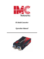
1
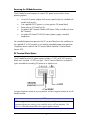
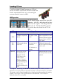
IE–ModeConverter
Operation Manual
FCC Radio Frequency Interference Statement
This equipment has been tested and found to comply with the limits for a Class B computing device, pursuant to Part 15 of the FCC Rules.
These limits are designed to provide reasonable protection against harmful interference when the equipment is operated in a commercial
environment. This equipment generates, uses and can radiate radio frequency energy and, if not installed and used in accordance with the
instruction manual, may cause harmful interference to radio communications. Operation of this equipment in a residential area is likely to
cause harmful interference in which the user will be required to correct the interference at his own expense.
Any changes or modifications not expressly approved by the manufacturer could void the user’s authority to operate the equipment.
The use of non-shielded I/O cables may not guarantee compliance with FCC RFI limits. This digital apparatus does not exceed the Class B
limits for radio noise emission from digital apparatus set out in the Radio Interference Regulation of the Canadian Department of
Communications.
Le présent appareil numérique n’émet pas de bruits radioélectriques dépassant les limites applicables aux appareils numériques de classe B
prescrites dans le Règlement sur le brouillage radioélectrique publié par le ministère des Communications du Canada.
Warranty
IMC Networks warrants to the original end-user purchaser that this product, EXCLUSIVE OF SOFTWARE, shall be free
from defects in materials and workmanship under normal and proper use in accordance with IMC Networks' instructions
and directions for a period of six (6) years after the original date of purchase. IMC Networks warrants to the original enduser purchaser that all SFPs shall be free from defects in materials and workmanship under normal and proper use in
accordance with IMC Networks' instructions and directions for a period of one (1) year after the original date of purchase.
This warranty is subject to the limitations set forth below.
At its option, IMC Networks will repair or replace at no charge the product which proves to be defective within such
warranty period. This limited warranty shall not apply if the IMC Networks product has been damaged by unreasonable
use, accident, negligence, service or modification by anyone other than an authorized IMC Networks Service Technician
or by any other causes unrelated to defective materials or workmanship. Any replaced or repaired products or parts carry
a ninety (90) day warranty or the remainder of the initial warranty period, whichever is longer.
To receive in-warranty service, the defective product must be received at IMC Networks no later than the end of the
warranty period. The product must be accompanied by proof of purchase, satisfactory to IMC Networks, denoting
product serial number and purchase date, a written description of the defect and a Return Merchandise Authorization
(RMA) number issued by IMC Networks. No products will be accepted by IMC Networks which do not have an RMA
number. For an RMA number, contact IMC Networks at PHONE: (800) 624-1070 (in the U.S. and Canada) or (949) 4653000 or FAX: (949) 465-3020. The end-user shall return the defective product to IMC Networks, freight, customs and
handling charges prepaid. End-user agrees to accept all liability for loss of or damages to the returned product during
shipment. IMC Networks shall repair or replace the returned product, at its option, and return the repaired or new
product to the end-user, freight prepaid, via method to be determined by IMC Networks. IMC Networks shall not be
liable for any costs of procurement of substitute goods, loss of profits, or any incidental, consequential, and/or special
damages of any kind resulting from a breach of any applicable express or implied warranty, breach of any obligation
arising from breach of warranty, or otherwise with respect to the manufacture and sale of any IMC Networks product,
whether or not IMC Networks has been advised of the possibility of such loss or damage.
EXCEPT FOR THE EXPRESS WARRANTY SET FORTH ABOVE, IMC NETWORKS MAKES NO OTHER WARRANTIES,
WHETHER EXPRESS OR IMPLIED, WITH RESPECT TO THIS IMC NETWORKS PRODUCT, INCLUDING WITHOUT
LIMITATION ANY SOFTWARE ASSOCIATED OR INCLUDED. IMC NETWORKS SHALL DISREGARD AND NOT BE
BOUND BY ANY REPRESENTATIONS OR WARRANTIES MADE BY ANY OTHER PERSON, INCLUDING EMPLOYEES,
DISTRIBUTORS, RESELLERS OR DEALERS OF IMC NETWORKS, WHICH ARE INCONSISTENT WITH THE WARRANTY
SET FORTH ABOVE. ALL IMPLIED WARRANTIES INCLUDING THOSE OF MERCHANTABILITY AND FITNESS FOR A
PARTICULAR PURPOSE ARE HEREBY LIMITED TO THE DURATION OF THE EXPRESS WARRANTY STATED ABOVE.
Every reasonable effort has been made to ensure that IMC Networks product manuals and promotional materials
accurately describe IMC Networks product specifications and capabilities at the time of publication. However, because of
ongoing improvements and updating of IMC Networks products, IMC Networks cannot guarantee the accuracy of printed
materials after the date of publication and disclaims liability for changes, errors or omissions.
ii
Table of Contents
FCC Radio Frequency Interference Statement ....................................................ii
Warranty............................................................................................................ii
About IE–ModeConverter...................................................................................1
Installing the IE–ModeConverter.........................................................................2
SFP Port Requirements.......................................................................................2
DIN Rail Mounting.............................................................................................2
Powering the IE–ModeConverter........................................................................3
DC Terminal Block Option.................................................................................3
Cascading DC Power .........................................................................................4
LED Operation...................................................................................................4
DC Power Supply Precautions............................................................................5
IMC Networks Technical Support.......................................................................5
Specifications .....................................................................................................6
Standards/Compliance .......................................................................................6
Fiber Optic Cleaning Guidelines.........................................................................6
Electrostatic Discharge Precautions.....................................................................7
Safety Certifications............................................................................................8
iii
About IE–ModeConverter
The IE–ModeConverter is a pure mode converter that converts any fiber optics type
to any other fiber optics type. This product is a Protocol independent converter and
is not intended for applications that require retiming or any Layer 2 functions. The
IE–ModeConverter supports extended temperature operation.
The IE–ModeConverter requires two small form-factor (SFP) modules (sold
separately), which provide greater fiber flexibility in the network environment. The
hot-swappable nature of the SFPs and the numerous fiber modes and types available
in SFPs allow for easy configuration and future upgrading as network demands
evolve. The SFP modules must be MSA compliant and support the same speed
range.
The IE–ModeConverter operates as a mode converter only and not as a rate
converter.
The IE–ModeConverter does not provide support for copper (TX) SFPs.
Features
The IE–ModeConverter provides the ability to change optical transport characteristics
using easy-to-install SFP devices. This mix-and-match functionality is only limited by
the available IMC Networks’ SFP units. For more information about SFPs, visit
https://www.imcnetworks.com/Products/Small_Form_Factor_Pluggable.cfm
The key features of the IE–ModeConverter are
• Uses Miniature Media Converter Form Factor
• Supports a 7 VDC to 50 VDC terminal block option with cascading power
• Supports an external 5 VDC power option (not extended temperature)
• Allows extended temperature range from -13°C to +185°F (-25°C to +85°
C)
• Uses all standard MSA-complaint SFP devices (excluding copper SFPs)
• Provides extensive diagnostic LED functions
• Supports DIN Rail mounting
Applications
The standard application is the conversion of a short-range, multi-mode fiber
interface to a long-range single-mode fiber line. In addition, CWDM, DWDM, or
single-strand fiber can be supported with the appropriate SFP. This allows you to
purchase low cost multi-mode fiber blade cards for your network equipment and
support long-distance single-mode fiber links.
1
Installing the IE–ModeConverter
The IE–ModeConverter installs anywhere as a standalone, table-top device or on a
DIN rail.
As a standalone device, install it in locations with limited space.
If multiple connections are required, use an IE-PowerTray/18 enclosure, (sold
separately). The tray allows for 18 conversions in a 1.5 rack unit of space. The units
can also be powered by daisy-chaining DC power (refer to Cascading DC Power).
SFP Port Requirements
The IE–ModeConverter requires two SFP Modules of the same speed, either two fast
Ethernet (100Mbps) modules or two Gigabit Ethernet (1000Mbps) modules.
NOTE
Both SFPs must operate at the same speed.
DIN Rail Mounting
The IE–ModeConverter can be mounted
with two DIN Rail clips, a hardware
option available through IMC Networks.
The DIN Rail clips include screws, to
allow the installation onto a DIN Rail.
Install the screws into DIN Rail clips,
which should be mounted perpendicular
to the DIN Rail. Snap the converter onto
the clips. To remove the converter from
the DIN Rail, use a flat-head screwdriver
into the slot to gently pry the converter
from the rail.
NOTE
The DIN clips are designed for use on a DIN-35 rail.
2
Powering the IE–ModeConverter
The IE–ModeConverter requires an external DC power source and has three
powering options:
•
•
•
•
•
Universal AC power adapter with country specific clip (not included with
module only version).
User supplied LPS DC power via a four-position DC power block.
Power from an IE- PowerTray/18.
An optional IMC Network Double-USB Power Cable (available only from
IMC Network)
An optional IE-Power/5V DIN Rail mount power supply, extended
temperature
For extended temperature operation the DC terminal block must be used because
the supplied AC to DC converter is not rated for extended temperature operation.
The power source used with the DC terminal block should be a Limited Power
Source (LPS).
DC Terminal Block Option
The IE–ModeConverter DC power option includes a 7 VDC to 50 VDC terminal
block and a standard +5 VDC mini-jack. The DC terminal block has multiple DC
inputs intended for cascading DC power to an adjacent unit.
Connect the power source to any one positive and one negative terminal on the IE–
ModeConverter.
NOTE
When using stranded wire, the leads must be tinned. The chassis is not
protected against mis-wiring; if mis-wired the chassis will not function. The
chassis is internally connected to the negative power terminal.
3
Cascading DC Power
If installing multiple IE–ModeConverters on a DIN rail,
you can use one DC input source and then cascade from
one DC terminal block to the next, until reaching the
maximum electrical current available.
LED Operation
The IE–ModeConverter contains four status LED
indicators. Each LED is dual color and has three
states: off, red, or green. A loss of signal on one
SFP causes the TX of the other SFP to turn off.
This action does not activate the red TX Fault
LED.
LED
Color or State
Red
OFF
Green
Unit does not have
power.
Power is applied to the card.
PWR
Card does not pass the
self-test.
SD I
SD 2
LED transmitter has an
active fault.
No active fault on
transmitter.
Valid signal is detected by
the SFP and LED transmitter
is not in fault.
All internal self-test functions
must pass before the PWR
LED is green.
LOS indication on
receiver.
MSA LEDs
One or both SFPs are
not installed or not
detected. The TX
inhibit must not be
active if a SFP is
missing.* Or, both
SFPs are installed, but
their speed settings are
different. This
condition disables both
SFPs.
N/A
Indicates that both SFPs with
the same speed are securely
installed.
* To help in troubleshooting, the Link Loss (LL) feature is always ON. That is, if a LOS is
detected on an incoming SFP port, the Optical transmitter on the other SFP port is turned OFF.
This provides a Link Loss carry forward function to alert the device downstream of the existing
problem. This function is "ON" in both directions at the same time. The LL function is
inhibited if either SFP is not installed.
4
DC Power Supply Precautions
The following precautions must be observed when installing the chassis model with
an internal DC power supply.
1.
Check nameplate ratings to ensure there is no overloading of supply circuits that
could effect overcurrent protection and supply wiring.
2.
In addition, the following must be observed:
a. Connect the equipment to a 35 to 50 VDC power source that is electrically
isolated from the alternating current source. The 35 to 50 VDC power
source is connected to a SELV DC source.
3.
b.
Route input wiring to terminal block and secure in such a manner that it is
protected from damage and stress. Do not route wiring past sharp edges or
moving parts.
c.
Incorporate a readily accessible disconnect device, with a 3mm minimum
contact gap in the fixed wiring.
Reliable Earthing of this equipment must be maintained. Particular attention
should be given to supply connections when connecting to power strips, rather
than direct connections to the branch circuit.
IMC Networks Technical Support
Tel: (949) 465-3000 or (800) 624-1070 (in the U.S. and Canada);
+32-16-550880 (Europe)
Fax: (949) 465-3020
E-Mail: [email protected]
Web: www.imcnetworks.com
5
Specifications
Input Specifications
AC Wall Adapter
100 to 240 ±10% VAC input, 5 VDC output, 2A max.
DC terminal
+7 VDC to +50 VDC @ 2.5 watts. Actual current
consumption may vary depending on the type of SFP
modules installed. When not using the supplied AC/DC
converter the externally supplied DC power must be
provided from a LPS source
5 VDC
Spec 500mA
Please note that the laptop or PC USB ports must be 2.0
or greater to provide sufficient power to the unit.
125W, 20A@ 5V
DC jack
Double-USB Power
Cable
Power Tray 18-Slot AC
for Miniature Converters
Operating Temperature:
-13°F to +185°F (-25°C to +85°C) DC configuration
-4°F to +158°F (-20°C to +70°C) DIN Railmount power supply
+14°F to +122°F (-10°C to +50°C) with AC wall adapter
Storage Temperature:
-49°F to +185°F (-45°C to +85°C)
Shipping Weight:
0.25 lbs (0.11 kg)
Dimensions:
0.83” H x 1.80” W x 3.35” D (2.11 x 4.57 x 8.51 cm)
Standards/Compliance
SFP-MSA SFP standard (September 14, 2000)
SFF-8472 DDMI standard (Revision 1.0)
All SFPs used in this product should be certified to IEC 60825-1.
Fiber Optic Cleaning Guidelines
Fiber Optic transmitters and receivers are extremely susceptible to contamination by
particles of dirt or dust, which can obstruct the optic path and cause performance
degradation. Good system performance requires clean optics and connector ferrules.
6
1.
Use fiber patch cords (or connectors, if you terminate your own fiber) only from
a reputable supplier; low-quality components can cause many hard-to-diagnose
problems in an installation.
2.
Dust caps are installed at IMC Networks to ensure factory-clean optical devices.
These protective caps should not be removed until the moment of connecting
the fiber cable to the device. Should it be necessary to disconnect the fiber
device, reinstall the protective dust caps.
3.
Store spare caps in a dust-free environment such as a sealed plastic bag or box
so that when reinstalled they do not introduce any contamination to the optics.
4.
If you suspect that the optics have been contaminated, alternate between
blasting with clean, dry, compressed air and flushing with methanol to remove
particles of dirt.
Electrostatic Discharge Precautions
Electrostatic discharge (ESD) can cause damage to any product, add-in modules or
stand alone units containing electronic components. Always observe the following
precautions when installing or handling these kinds of products
1.
Do not remove unit from its protective packaging until ready to install.
2.
Wear an ESD wrist grounding strap before handling any module or component.
If the wrist strap is not available, maintain grounded contact with the system unit
throughout any procedure requiring ESD protection.
3.
Hold the units by the edges; do not touch the electronic components or gold
connectors.
4.
After removal, always place the boards on a grounded, static-free surface, ESD
pad or in a proper ESD bag. Do not slide the modules or stand alone units over
any surface.
WARNING! Integrated circuits and fiber optic components are
extremely susceptible to electrostatic discharge damage. Do not
handle these components directly unless you are a qualified service
technician and use tools and techniques that conform to accepted
industry practices.
7
Safety Certifications
UL/CUL: Listed to Safety of Information Technology Equipment, including
Electrical Business Equipment.
CE: The products described herein comply with the Council Directive on
Electromagnetic Compatibility (2004/108/EC) and the Council
Directive on Electrical Equipment Designed for use within Certain
Voltage Limits (2006/95/EC). Certified to Safety of Information
Technology Equipment, Including Electrical Business Equipment. For
further details, contact IMC Networks.
Class 1 Laser product, Luokan 1 Laserlaite,
Laser Klasse 1, Appareil A’Laser de Classe 1
European Directive 2002/96/EC (WEEE) requires that any equipment that bears this
symbol on product or packaging must not be disposed of with unsorted municipal
waste. This symbol indicates that the equipment should be disposed of separately
from regular household waste. It is the consumer’s responsibility to dispose of this
and all equipment so marked through designated collection facilities appointed by
government or local authorities. Following these steps through proper disposal and
recycling will help prevent potential negative consequences to the environment and
human health. For more detailed information about proper disposal, please contact
local authorities, waste disposal services, or the point of purchase for this equipment.
8
19772 Pauling • Foothill Ranch, CA 92610-2611 USA
TEL: (949) 465-3000 • FAX: (949) 465-3020
www.imcnetworks.com
© 2010 IMC Networks. All rights reserved.
The information in this document is subject to change without notice. IMC Networks assumes no responsibility for any
errors that may appear in this document. IE–ModeConverter is a trademark of IMC Networks. Other brands or product
names may be trademarks and are the property of their respective companies.
Document Number 55-80619-00 A4
November 2010