1
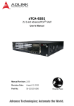
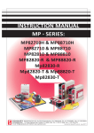
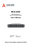
USB-7230/7250 USB 2.0-based Digital I/O Module User’s Manual Manual Rev.: 2.00 Revision Date: Nov. 16, 2012 Part No: 50-1Z138-2000 Advance Technologies; Automate the World. Revision History Revision Release Date Description of Change(s) 2.00 Nov. 16, 2012 Initial release USB-7230/7250 Preface Copyright 2012 ADLINK Technology, Inc. This document contains proprietary information protected by copyright. All rights are reserved. No part of this manual may be reproduced by any mechanical, electronic, or other means in any form without prior written permission of the manufacturer. Disclaimer The information in this document is subject to change without prior notice in order to improve reliability, design, and function and does not represent a commitment on the part of the manufacturer. In no event will the manufacturer be liable for direct, indirect, special, incidental, or consequential damages arising out of the use or inability to use the product or documentation, even if advised of the possibility of such damages. Environmental Responsibility ADLINK is committed to fulfill its social responsibility to global environmental preservation through compliance with the European Union's Restriction of Hazardous Substances (RoHS) directive and Waste Electrical and Electronic Equipment (WEEE) directive. Environmental protection is a top priority for ADLINK. We have enforced measures to ensure that our products, manufacturing processes, components, and raw materials have as little impact on the environment as possible. When products are at their end of life, our customers are encouraged to dispose of them in accordance with the product disposal and/or recovery programs prescribed by their nation or company. Conventions Take note of the following conventions used throughout this manual to make sure that users perform certain tasks and instructions properly. Preface iii Additional information, aids, and tips that help users perform tasks. NOTE: CAUTION: WARNING: iv Information to prevent minor physical injury, component damage, data loss, and/or program corruption when trying to complete a task. Information to prevent serious physical injury, component damage, data loss, and/or program corruption when trying to complete a specific task. Preface USB-7230/7250 Table of Contents Revision History...................................................................... ii Preface .................................................................................... iii List of Figures ....................................................................... vii List of Tables.......................................................................... ix 1 Introduction ........................................................................ 1 1.1 Overview.............................................................................. 1 1.2 Features............................................................................... 1 1.3 Applications ......................................................................... 2 1.4 Specifications....................................................................... 2 1.4.1 General Specifications................................................ 2 1.4.2 Digital Input (DI).......................................................... 2 1.4.3 Digital Output (DO) ..................................................... 3 1.5 Software Support ................................................................. 4 1.6 Driver Support for Windows................................................. 4 1.7 Utilities for Windows ............................................................ 5 1.8 Schematics and Dimensions ............................................... 6 1.9 1.8.1 Module........................................................................ 6 1.8.2 Module Stand ............................................................. 9 1.8.3 Rail Mounting............................................................ 15 1.8.4 Wall Mounting........................................................... 18 Connector Pin Assignment ................................................ 20 2 Getting Started ................................................................. 23 2.1 Unpacking Checklist .......................................................... 23 2.2 Connecting the USB-7230/7250 Module ........................... 23 2.3 Device ID ........................................................................... 24 Table of Contents v 3 Operations ......................................................................... 27 3.1 Isolated Digital Input .......................................................... 28 3.2 Change of State (COS) Detection...................................... 29 3.3 Optical Isolated Frequency/Event Counter ........................ 31 3.4 Digital Filtering ................................................................... 33 3.5 Isolated Digital Output (USB-7230 only) ............................ 34 3.6 Relay Output (USB-7250 only) .......................................... 35 Important Safety Instructions............................................... 37 Getting Service ...................................................................... 39 vi Table of Contents USB-7230/7250 List of Figures Figure 1-1: Figure 1-2: Figure 1-3: Figure 1-4: Figure 1-5: Figure 1-6: Figure 1-7: Figure 1-8: Figure 1-9: Figure 1-10: Figure 1-11: Figure 1-12: Figure 1-13: Figure 1-14: Figure 1-15: Figure 2-1: Figure 3-1: Figure 3-2: Figure 3-3: Figure 3-4: Figure 3-5: Figure 3-6: Figure 3-7: Figure 3-8: Figure 3-9: Figure 3-10: Figure 3-11: Figure 3-12: Figure 3-13: List of Figures USB-7230/7250 Module Rear View............................ 6 USB-7230/7250 Module Side View ............................ 7 USB-7230 Module Front View .................................... 8 USB-7250 Module Front View .................................... 9 Module, Stand, Connector, and USB Cable ............. 10 Module, Stand, & Wall Mount Kit Side View (w/ connections)11 Module in Stand Front View ..................................... 12 Module Stand Top View ........................................... 13 Module Stand Side Cutaway View ........................... 14 Module Stand Front View ......................................... 14 Rail Mount Kit ........................................................... 15 Module Pre-Rail Mounting ........................................ 16 Module Rail-Mounted ............................................... 17 Wall Mount Holes ..................................................... 18 Module with Wall Mount Apparatus .......................... 19 Device ID Selection Control...................................... 24 USB-7230 Functional Block Diagram ....................... 27 USB-7250 Functional Block Diagram ....................... 28 USB-7230 Isolated Input .......................................... 29 USB-7250 Isolated Input .......................................... 29 COS Detection Architecture ..................................... 30 COS Example........................................................... 31 USB-7230/7250 Optical Isolated Frequency/Event Counter31 Frequency Counter Example.................................... 32 Frequency Counter Error %...................................... 33 Digital Filter Example................................................ 34 USB-7230 Isolated Output........................................ 35 Form C Relay ........................................................... 35 Form A Relay............................................................ 35 vii This page intentionally left blank. viii List of Figures USB-7230/7250 List of Tables Table Table Table Table 1-1: 1-2: 1-3: 1-4: List of Tables USB-7230 Pin Assignment ............................................ 20 USB-7230 I/O Signal Description .................................. 21 USB-7250 Pin Assignment ............................................ 22 USB-7250 I/OSignal Description ................................... 22 ix This page intentionally left blank. x List of Tables USB-7230/7250 1 Introduction 1.1 Overview The USB-7230/7250 are USB-based digital I/O modules, featuring high voltage ON/OFF control and monitoring, and isolation voltage supported up to 2500VRMS. The USB-7230 provides 32-channel isolated digital I/O and 2-channel frequency/event counters, and USB-7250 provides 8-channel isolated digital inputs, 8-channel solid-state relays, and 2-channel frequency/event counters. The USB-powered USB-7230/7250 have removable screw-down terminals for easy device connectivity, and the included multi-functional stand fully supports desktop, rail, or wall mounting. The USB-7230/7250 are suitable for industrial I/O control applications requiring high voltage and excellent protection. High isolation voltage protects against damage from accidental contact with high external voltage and eliminates troublesome ground loops. U-Test, a free ready-to-use testing program, is included to enable operation or testing of all ADLINK USB DAQ series functions with no programming requirement. 1.2 Features X High-speed USB 2.0 X USB-powered X USB-7230: 16CH isolated DI, 16CH isolated DO, 2CH frequency/event counters X USB-7250: 8CH solid state relays, 8CH isolated DI, 2CH frequency/event counters X Programmable digital filter removing unexpected glitches on input channels X Programmable initial DO status X Up to 2500VRMS isolation voltage X Removable screw-down terminal on module X Lockable USB cable for secure connectivity X Ready-to-use testing application (U-Test) included Introduction 1 1.3 Applications X Automotive testing X Laboratory research X Industrial I/O control X Signal switching 1.4 Specifications 1.4.1 General Specifications Physical, Power, and Operating Environment Interface High speed USB 2.0 compatible, mini-USB connector Dimensions 156.5 (L) x 114 (W) x 41.3 (H) mm (6.16 X 4.49 X 1.63 in.) I/O Connector Two 20-pin removable screw-down terminals Power requirement USB power (5 V @ 400 mA) Operating environment Ambient temperature: 0 to 55°C Relative humidity: 10% to 90%, non-condensing Storage environment Ambient temperature: -20 to 70 °C Relative humidity: 5% to 95%, non-condensing 1.4.2 Digital Input (DI) USB-7230 USB-7250 Number of channels 16 8 Polarity Bi-directional (non-polarity) Optical Isolated Input Logic level VIH=5~24V, VIL=0~1.5V Or dry contact Input resistance 2.4k @ 0.5W Isolated voltage 2500VRMS (channel to system) 2 Introduction USB-7230/7250 USB-7230 Min. pulse width for change of state (COS) detection USB-7250 20.83 ns (software programmable) Data transfer Programmed I/O Optical Isolated Frequency/Event Counter Number of channels 2 Logic level VIH=5~12V, VIL=0~1.5V Event counter width 32-bit Max. input frequency (DC coupled) 1 MHz Min. input frequency (DC coupled) 0.1 Hz Max. frequency error 0.5% (f≤50kHz) 1% (50kHz<f≤500kHz) 2% (500kHz<f≤1MHz) Data transfer 1.4.3 Programmed I/O Digital Output (DO) USB-7230 Channels 16 (optical isolation) Output type Open drain MOSFET Supply voltage 5-35VDC Max. sink current 250 mA @ 100% duty (/channel) Data transfer Programmed I/O USB-7250 Channels 8 (solid state relay, non-latching) Contact rating (/channel) Max. switching power 60 W, 125 VA Max. switching voltage 220 VDC, 250VAC Max. switching current 2A Relay ON/OFF time Operate time 2 ms Release time 1 ms Contact resistance 75mΩ (max.) Expected lifetime 50 VDC 0.1A (resistive), 1x10⁶ operations Introduction 3 Breakdown voltage 1000 VAC Data transfer Programmed I/O 1.5 Software Support ADLINK provides comprehensive software drivers and packages to suit various user approaches to system building. In addition to programming libraries, such as DLLs, for most Windows-based systems, ADLINK also provides drivers for other application environments such as LabVIEW® and MATLAB®. ADLINK also pro vides ActiveX component ware for measurement and SCADA/HMI, and breakthrough proprietary software. All software options are included in the ADLINK All-in-One CD. Be sure to install the driver & utility before use. 1.6 Driver Support for Windows UD-DASK UD-DASK is composed of advanced 32/64-bit kernel drivers for customized DAQ application development. USB-DASK enables you to perform detailed operations and achieve superior performance and reliability from the data acquisition system. DASK kernel drivers now support Windows 7/Vista® OS. Only UD-DASK versions 1.0.5 and later support the USB-7230/7250 module. NOTE: DAQPilot DAQPilot is a SDK with a graphics-driven interface for various application development environments. DAQPilot represents ADLINK's commitment to full support of its comprehensive line of data acquisition products and is designed for novice to most 4 Introduction USB-7230/7250 experienced programmers. As a task-oriented DAQ driver, SDK and wizard for Windows systems, DAQPilot helps shorten development time while accelerating the learning curve for data acquisition programming. Download and install DAQPilot from: http://www.adlinktech.com/TM/DAQPilot.html Only UD-DASK versions 2.3.4.1109 and later and later support the USB-7230/7250 module. NOTE: 1.7 Utilities for Windows U-Test U-Test is a free and ready-to-use utility assisting instant testing and operation of all ADLINK USB DAQ product functions with no programming requirment. In addition to data collection and monitoring functions, U-Test also supports basic FFT analysis and direct control of analog output and digital I/O with a user-friendly interface. Download and install U-Test from: http://www.adlinktech.com Introduction 5 1.8 Schematics and Dimensions All dimensions shown are in millimeters (mm) NOTE: 1.8.1 Module Figure 1-1: USB-7230/7250 Module Rear View 6 Introduction USB-7230/7250 114 156.5 Figure 1-2: USB-7230/7250 Module Side View Introduction 7 114 41.3 Figure 1-3: USB-7230 Module Front View 8 Introduction USB-7230/7250 114 41.3 Figure 1-4: USB-7250 Module Front View 1.8.2 Module Stand The multi-function USB-7230/7250 stand is compatible with desk, rail, or wall mounting. To fix the module in the stand, slide the module body into the stand until a click is heard. To remove the module Introduction 9 from the stand, twist the bottom of the stand in a back-and forth motion and separate from the module. Figure 1-5: Module, Stand, Connector, and USB Cable 10 Introduction USB-7230/7250 200.1 169.4 156.5 Figure 1-6: Module, Stand, & Wall Mount Kit Side View (w/ connections) Introduction 11 114.3 Figure 1-7: Module in Stand Front View 12 Introduction USB-7230/7250 26 B 20.4 20.4 Figure 1-8: Module Stand Top View Introduction 13 5.89 1.5 3.4 6 Figure 1-9: Module Stand Side Cutaway View 100 Figure 1-10: Module Stand Front View 14 Introduction USB-7230/7250 1.8.3 Rail Mounting The multi-function stand can be mounted on the DIN rail using the rail-mount kit as shown. Figure 1-11: Rail Mount Kit Introduction 15 Figure 1-12: Module Pre-Rail Mounting 16 Introduction USB-7230/7250 Figure 1-13: Module Rail-Mounted Introduction 17 1.8.4 Wall Mounting The multi-function stand can be fixed to a wall using four flush head screws as shown. The four screw holes should be approximately 3.4 mm in diameter. 20.4 13.0 Figure 1-14: Wall Mount Holes 18 Introduction USB-7230/7250 Figure 1-15: Module with Wall Mount Apparatus Introduction 19 1.9 Connector Pin Assignment The USB-7230/7250 module is equipped with 40-pin removable screw-down terminal connectors, with pin assignment as follows. Pin Function Pin Function 20 VDD 40 DO15 19 DO7 39 DO14 18 DO6 38 DO13 17 DO5 37 DO12 16 DO4 36 DO11 15 DO3 35 DO10 14 DO2 34 DO9 13 DO1 33 DO8 12 DO0 32 IGND 11 IGND 31 IGND 10 CNT0 30 CNT1 9 CGND 29 COM 8 DI7 28 DI15 7 DI6 27 DI14 6 DI5 26 DI13 5 DI4 25 DI12 4 DI3 24 DI11 3 DI2 23 DI10 2 DI1 22 DI9 1 DI0 21 DI8 Table 1-1: USB-7230 Pin Assignment Signal Name Reference Direction Description DI<0..15> COM I 20 Isolated digital input channel Introduction USB-7230/7250 Signal Name Reference COM -------- CNT<0,1> CGND CGND -------- DO<0..15> IGND IGND -------- VDD IGND Direction Description Common ground or common power of isolated digital input channel I Frequency/event counter channel Ground of Frequency/event counter O Isolated digital output channel Ground return path for isolated output channel I Common power input junction for isolated output channel Table 1-2: USB-7230 I/O Signal Description Introduction Pin Function Pin Function 20 NO7 40 GND1 19 COM7 39 CNT1 18 NO6 38 GND0 17 COM6 37 CNT0 16 NO5 36 DI7L 15 COM5 35 DI7H 14 NO4 34 DI6L 13 COM4 33 DI6H 12 NC3 32 DI5L 11 NO3 31 DI5H 10 COM3 30 DI4L 9 NC2 29 DI4H 8 NO2 28 DI3L 7 COM2 27 DI3H 6 NC1 26 DI2L 5 NO1 25 DI2H 21 Pin Function Pin Function 4 COM1 24 DI1L 3 NC0 23 DI1H 2 NO0 22 DI0L 1 COM0 21 DI0H Table 1-3: USB-7250 Pin Assignment Signal Name Reference Direction Description COM<0..7> ---------- I Common pin of relay <0..7> NO<0..7> COM<0..7> I Normal open pin of relay <0..7> NC<0..3> COM<0..3> I Normal close pin of relay <0..3> DI<0..7>H DI<0..7>L I High input of isolated differential digital input DI<0..7>L -------- I Low input of isolated differential digital input CNT<0,1> GND<0,1> I Frequency/event counter channel GND<0,1> -------- Ground of Frequency/event counter Table 1-4: USB-7250 I/OSignal Description 22 Introduction USB-7230/7250 2 Getting Started WARNING: The appropriate driver must be installed before connection to the computer system. See Section 1.5: Software Support for driver support information. 2.1 Unpacking Checklist Before unpacking, check the shipping carton for any damage. If the shipping carton and/or contents are damaged, inform the dealer immediately. Retain the shipping carton and packing materials for inspection. Obtain authorization from the dealer before returning any product to ADLINK. Ensure that the following items are included in the package. X USB-7230/7250 X Stand X Two removable screw terminals X USB cable (2-meter length) X Railmount kit X ADLINK All-in-One CD X User’s manual 2.2 Connecting the USB-7230/7250 Module 1. Turn on the computer. 2. Connect the USB-7230/7250 module to one USB 2.0 port on the computer using the included USB cable. 3. The first time the USB-7230/7250 module is connected, a New Hardware message appears. It will take a few seconds to load the firmware. When loading is complete, the LED indicator on the rear of the USB DAQ module changes from amber to green and the New Hardware message closes. 4. The USB-7230/7250 module can now be located in the hardware Device Manager. Getting Started 23 NOTE: The USB-7230/7250 module is exclusively powered by the USB port and requires 400 mA @ 5 V. If the USB-7230/7250 module cannot be detected, power provided by the USB port may be insufficient. 2.3 Device ID A rotary control on the rear of the module (as shown) controls device ID setting and can be set from 0 to 7. The device ID allows dedicated control of the USB-7230/7250 module irrespective of the connected USB port. When more than one USB module of the same type is connected, each must be set to a different ID to avoid conflicts and errors in operation. Figure 2-1: Device ID Selection Control 24 Getting Started USB-7230/7250 All remaining hardware configuration is software programmable, including sampling/update rate, input/output channel, input range, and others. Please see the UD-DASK Function Reference manual for details. Getting Started 25 This page intentionally left blank. 26 Getting Started USB-7230/7250 3 Operations Figure 3-1: USB-7230 Functional Block Diagram The USB-7250 provides 8CH optical isolation digital inputs, 8CH relay outputs (4CH form C and 4CH form A), and 2CH frequency/event counters. Operations 27 Figure 3-2: USB-7250 Functional Block Diagram 3.1 Isolated Digital Input The USB-7230/7250 support 16 or 8 opto-isolated input channels,as follows, with digital input first routed through a photo-coupler (PC3H4), and normal input voltage range for high state from 5 to 24V. NOTE: 28 For USB-7230, all digital inputs share the same common junction (COM), with connections either common power or common ground, and with USB-7250, each input channel has an individual differential input pair, preventing connections from being polarity sensitive, irrespective of the connected voltage. Operations USB-7230/7250 Figure 3-3: USB-7230 Isolated Input Figure 3-4: USB-7250 Isolated Input 3.2 Change of State (COS) Detection COS (Change of State) refers to input state (logic level) changing from low to high or vice versa, wherein the COS detection circuit registers the edge of the level change. Operations 29 In the USB-7230/7250, the COS detection circuit is applied to all DI channels, with the channel(s) to enable COS detection selectable by software. When an enabled channel changes logic level, the COS detection circuit generates an interrupt request to the USB microcontroller, which, when detected, latches corresponding DI data into the COS latch register. In COS architecture, DI data is sampled by a 48 MHz base clock, such that pulse width of the digital input exceeds 21 ns, or the COS latch register cannot latch the correct input data. The COS latch register is cleared when the register is read out, resuming availability to latch the susequent COS. NOTE: DI0-DI7 Maximum frequency of COS detection depends on software latency and computer performance, and is not guaranteed if COS frequency exceeds 1 kHz. Digital DI0-DI7 Filter 0~7 CPLD INT USB Bridge DI8-DI15 Digital DI8-DI15 Filter 8~15 USB BUS Figure 3-5: COS Detection Architecture 30 Operations USB-7230/7250 DI (all channels enable) 0027 0028 0029 FFFF Interrupt Request Interrupt Clear COS Latch register XXXX 0028 FFFF Figure 3-6: COS Example 3.3 Optical Isolated Frequency/Event Counter Calculates the number of rising or falling edges occurring on the input channel, with counter width of 32 bits counting up from 0. The polarity (rising or falling edge) of valid events is software configurable. PHOTO COUPLER n=0,1 Figure 3-7: USB-7230/7250 Optical Isolated Frequency/Event Counter The frequency counter base clock is 48MHz. The frequency counter calculates base clocks occurring within a period (rising edge to rising edge or falling edge to falling edge) of the repetitive input signal, which is then converted to frequency value. Counter polarity can be adjusted to rising edge active or falling edge active. The following example shows frequency measurement of a 1 MHz signal by counter0 with rising-edge polarity and 500 kHz signal by Operations 31 counter1 with falling-edge polarity. Counter value is updated and reset in every period. CLK CNT0 Polarity Freq = 1 MHz CNT0 CNT0 FREQ 1 2 3 46 47 48 1 24 1 CNT1 Polarity Freq = 500 KHz CNT1 CNT1 FREQ 1 24 1 Figure 3-8: Frequency Counter Example Since the signals are sampled by a 48MHz base clock, latch timing can generate measurement error, maximum error ratio vs. input frequency is as follows. 32 Operations USB-7230/7250 2 1.5 Error (%) 1 .5 100 1000 10000 100000 1000000 Frequency (Hz) Figure 3-9: Frequency Counter Error % 3.4 Digital Filtering Filters unexpected glitch signals from the input channels. By default, when enabled, the input channel ignores signal changes from one state to another when not remaining in the state for a pre-defined period. The digital filter function is applied on all DI channels and counters, with the default setting disabled. When enabled by software,it is necessary to configure the minimum pulse-width value. This value represents the minimum period of time guaranteed to pass through the filter when the signal changes. The digital filter uses an internal 16-bit counter to define the specified filter value. Data is sampled by a 48 MHz base clock, with minimum pulse-width value a multiple of 20.83 ns and multiple number from 1 to 65535, representing the minimum pulse-width from 20.83 ns to 1.365 ms. In an examplary digital filter operation, as shown, data is sampled by a 48 MHz base clock, and filter stage is 10, such that minimum pulse width value is 208.3 ns. The pulse width of the first two signals is 180 ns, shorter than the specified filter value 208.3 ns. Accordingly, the first two pulses are ignored, and the next two signals, with pulse width of 230 ns (longer than the specified filter value 208.3 ns) are recognized. When pulse width of last two sig- Operations 33 nals is 180 ns when filter is disabled, definitely, the last two states are recognized. 1 2 8 9 1 2 8 9 1 2 8 9 10 1 2 8 9 10 1 2 8 9 1 2 8 9 1 2 CLK filter enable filter stage 000A Pulse Width = 180 ns XXXX Pulse Width = 180 ns Pulse Width = 210 ns filter_in Pulse Width = 180 ns filter_out Pulse Width = 210 ns Pulse Width = 210 ns Pulse Width = 180 ns Pulse Width = 180 ns Pulse Width = 210 ns Pulse Width = 180 ns Figure 3-10: Digital Filter Example To reject a signal deviating from a state for the specified period of time (minimum pulse width), the filter stage must be set to agree with: 20.83 ns × filter stage < minimum pulse Width (ns). 3.5 Isolated Digital Output (USB-7230 only) As shown, when isolated digital output is ON, sink current is conducted through the power MOSFET, and when OFF, no current flows through the power MOSFET. When the load is of an “inductance nature” such as a relay, coil or motor, the VDD pin must be connected to an external power source, in order for the flywheel diode to form a current-release closed loop, protecting the power MOSFET from high reverse voltage generated by the inductance load when the output is switched. The DO output status is saved in the USB microcontroller and can be read back if necessary. The USB-7230 also features programmable power-up output status,allowing output in a known state when powered on. When the module is powered off (ejected from the USB port), all digital output reverts to OFF. 34 Operations USB-7230/7250 VDD DO_n Controller (n=0~15) PHOTO COUPLER 5V DOn LOAD 5~35V IGND IGND Figure 3-11: USB-7230 Isolated Output 3.6 Relay Output (USB-7250 only) USB-7250 provides Form C and Form A relays, with channels 0 to 3 Form C, and 4 to 7 form A, as shown. Figure 3-12: Form C Relay Figure 3-13: Form A Relay Form C relays have NC (Normal Close), NO (Normal Open), and COM (Common) contacts. The COM terminal, located in the center,must contact either the NO pole or NC pole. When the control bit is high (1), contact is made between the COM terminal and NO pole, and if low (0), between the COM terminal and NC pole. Form Operations 35 A relays have only NO (Normal Open) and COM (Common) contacts. When the control bit is high (1), the COM terminal znd NO pole contact. If the control bit is low (0), no contact takes place. Current relay output status can be read back by software, and during normal power up, reset, and power down (ejection from USB port), the relay is low status. In addition, USB-7250 also features programmable power-up output status, providing output state when powered up. 36 Operations USB-7230/7250 Important Safety Instructions For user safety, please read and follow all instructions, WARNINGS, CAUTIONS, and NOTES marked in this manual and on the associated equipment before handling/operating the equipment. X Read these safety instructions carefully. X Keep this user’s manual for future reference. X Read the specifications section of this manual for detailed information on the operating environment of this equipment. X When installing/mounting or uninstalling/removing equipment: Z X Turn off power and unplug any power cords/cables. To avoid electrical shock and/or damage to equipment: Z Keep equipment away from water or liquid sources; Z Keep equipment away from high heat or high humidity; Z Keep equipment properly ventilated (do not block or cover ventilation openings); Z Make sure to use recommended voltage and power source settings; Z Always install and operate equipment near an easily accessible electrical socket-outlet; Z Secure the power cord (do not place any object on/over the power cord); Z Only install/attach and operate equipment on stable surfaces and/or recommended mountings; and, Z If the equipment will not be used for long periods of time, turn off and unplug the equipment from its power source. Important Safety Instructions 37 X Never attempt to fix the equipment. Equipment should only be serviced by qualified personnel. A Lithium-type battery may be provided for uninterrupted, backup or emergency power. Risk of explosion if battery is replaced with an incorrect type; please dispose of used batteries appropriately. X 38 Equipment must be serviced by authorized technicians when: Z The power cord or plug is damaged; Z Liquid has penetrated the equipment; Z It has been exposed to high humidity/moisture; Z It is not functioning or does not function according to the user’s manual; Z It has been dropped and/or damaged; and/or, Z It has an obvious sign of breakage. Important Safety Instructions USB-7230/7250 Getting Service Contact us should you require any service or assistance. ADLINK Technology, Inc. Address: 9F, No.166 Jian Yi Road, Zhonghe District New Taipei City 235, Taiwan ᄅؑקխࡉ৬ԫሁ 166 ᇆ 9 ᑔ Tel: +886-2-8226-5877 Fax: +886-2-8226-5717 Email: [email protected] Ampro ADLINK Technology, Inc. Address: 5215 Hellyer Avenue, #110, San Jose, CA 95138, USA Tel: +1-408-360-0200 Toll Free: +1-800-966-5200 (USA only) Fax: +1-408-360-0222 Email: [email protected] ADLINK Technology (China) Co., Ltd. Address: Ϟ⍋Ꮦ⌺ϰᮄऎᓴ∳催⾥ᡔುऎ㢇䏃 300 ো(201203) 300 Fang Chun Rd., Zhangjiang Hi-Tech Park, Pudong New Area, Shanghai, 201203 China Tel: +86-21-5132-8988 Fax: +86-21-5132-3588 Email: [email protected] ADLINK Technology Beijing Address: ࣫ҀᏖ⍋⎔ऎϞഄϰ䏃 1 োⲜ߯ࡼॺ E ᑻ 801 ᅸ(100085) Rm. 801, Power Creative E, No. 1, B/D Shang Di East Rd., Beijing, 100085 China Tel: +86-10-5885-8666 Fax: +86-10-5885-8625 Email: [email protected] ADLINK Technology Shenzhen Address: ⏅ഇᏖफቅऎ⾥ᡔುफऎ催ᮄफϗ䘧᭄ᄫᡔᴃು A1 ᷟ 2 ὐ C ऎ (518057) 2F, C Block, Bldg. A1, Cyber-Tech Zone, Gao Xin Ave. Sec. 7, High-Tech Industrial Park S., Shenzhen, 518054 China Tel: +86-755-2643-4858 Fax: +86-755-2664-6353 Email: [email protected] ADLINK Technology (Europe) GmbH Address: Nord Carree 3, 40477 Duesseldorf, Germany Tel: +49-211-495-5552 Fax: +49-211-495-5557 Email: [email protected] Getting Service 39 ADLINK Technology, Inc. (French Liaison Office) Address: 15 rue Emile Baudot, 91300 Massy CEDEX, France Tel: +33 (0) 1 60 12 35 66 Fax: +33 (0) 1 60 12 35 66 Email: [email protected] ADLINK Technology Japan Corporation Address: ͱ101-0045 ᵅҀ䛑गҷ⬄ऎ⼲⬄䤯 ⬎ފ3-7-4 ⼲⬄ 374 ɛɳ 4F KANDA374 Bldg. 4F, 3-7-4 Kanda Kajicho, Chiyoda-ku, Tokyo 101-0045, Japan Tel: +81-3-4455-3722 Fax: +81-3-5209-6013 Email: [email protected] ADLINK Technology, Inc. (Korean Liaison Office) Address: 昢殾柢 昢爎割 昢爎壟 1675-12 微汾瘶捒娯 8 猻 8F Mointer B/D,1675-12, Seocho-Dong, Seocho-Gu, Seoul 137-070, Korea Tel: +82-2-2057-0565 Fax: +82-2-2057-0563 Email: [email protected] ADLINK Technology Singapore Pte. Ltd. Address: 84 Genting Lane #07-02A, Cityneon Design Centre, Singapore 349584 Tel: +65-6844-2261 Fax: +65-6844-2263 Email: [email protected] ADLINK Technology Singapore Pte. Ltd. (Indian Liaison Office) Address: 1st Floor, #50-56 (Between 16th/17th Cross) Margosa Plaza, Margosa Main Road, Malleswaram, Bangalore-560055, India Tel: +91-80-65605817, +91-80-42246107 Fax: +91-80-23464606 Email: [email protected] ADLINK Technology, Inc. (Israeli Liaison Office) Address: 6 Hasadna St., Kfar Saba 44424, Israel Tel: +972-9-7446541 Fax: +972-9-7446542 Email: [email protected] 40 Getting Service