1
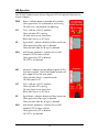
IE-iMcV-ModeConverter
Operation Manual
FCC Radio Frequency Interference Statement
This equipment has been tested and found to comply with the limits for a Class B computing device, pursuant to Part 15 of the FCC Rules.
These limits are designed to provide reasonable protection against harmful interference when the equipment is operated in a commercial
environment. This equipment generates, uses and can radiate radio frequency energy and, if not installed and used in accordance with the
instruction manual, may cause harmful interference to radio communications. Operation of this equipment in a residential area is likely to
cause harmful interference in which the user will be required to correct the interference at his own expense.
Any changes or modifications not expressly approved by the manufacturer could void the user’s authority to operate the equipment.
The use of non-shielded I/O cables may not guarantee compliance with FCC RFI limits. This digital apparatus does not exceed the Class B
limits for radio noise emission from digital apparatus set out in the Radio Interference Regulation of the Canadian Department of
Communications.
Le présent appareil numérique n’émet pas de bruits radioélectriques dépassant les limites applicables aux appareils numériques de classe B
prescrites dans le Règlement sur le brouillage radioélectrique publié par le ministère des Communications du Canada.
Warranty
IMC Networks warrants to the original end-user purchaser that this product, EXCLUSIVE OF SOFTWARE, shall be free
from defects in materials and workmanship under normal and proper use in accordance with IMC Networks' instructions
and directions for a period of six (6) years after the original date of purchase. This warranty is subject to the limitations set
forth below.
At its option, IMC Networks will repair or replace at no charge the product which proves to be defective within such
warranty period. This limited warranty shall not apply if the IMC Networks product has been damaged by unreasonable
use, accident, negligence, service or modification by anyone other than an authorized IMC Networks Service Technician
or by any other causes unrelated to defective materials or workmanship. Any replaced or repaired products or parts carry
a ninety (90) day warranty or the remainder of the initial warranty period, whichever is longer.
To receive in-warranty service, the defective product must be received at IMC Networks no later than the end of the
warranty period. The product must be accompanied by proof of purchase, satisfactory to IMC Networks, denoting
product serial number and purchase date, a written description of the defect and a Return Merchandise Authorization
(RMA) number issued by IMC Networks. No products will be accepted by IMC Networks which do not have an RMA
number. For an RMA number, contact IMC Networks at PHONE: (800) 624-1070 (in the U.S and Canada) or (949) 4653000 or FAX: (949) 465-3020. The end-user shall return the defective product to IMC Networks, freight, customs and
handling charges prepaid. End-user agrees to accept all liability for loss of or damages to the returned product during
shipment. IMC Networks shall repair or replace the returned product, at its option, and return the repaired or new
product to the end-user, freight prepaid, via method to be determined by IMC Networks. IMC Networks shall not be
liable for any costs of procurement of substitute goods, loss of profits, or any incidental, consequential, and/or special
damages of any kind resulting from a breach of any applicable express or implied warranty, breach of any obligation
arising from breach of warranty, or otherwise with respect to the manufacture and sale of any IMC Networks product,
whether or not IMC Networks has been advised of the possibility of such loss or damage.
EXCEPT FOR THE EXPRESS WARRANTY SET FORTH ABOVE, IMC NETWORKS MAKES NO OTHER WARRANTIES,
WHETHER EXPRESS OR IMPLIED, WITH RESPECT TO THIS IMC NETWORKS PRODUCT, INCLUDING WITHOUT
LIMITATION ANY SOFTWARE ASSOCIATED OR INCLUDED. IMC NETWORKS SHALL DISREGARD AND NOT BE
BOUND BY ANY REPRESENTATIONS OR WARRANTIES MADE BY ANY OTHER PERSON, INCLUDING EMPLOYEES,
DISTRIBUTORS, RESELLERS OR DEALERS OF IMC NETWORKS, WHICH ARE
INCONSISTENT WITH THE WARRANTY SET FORTH ABOVE. ALL IMPLIED WARRANTIES INCLUDING THOSE OF
MERCHANTABILITY AND FITNESS FOR A PARTICULAR PURPOSE ARE HEREBY LIMITED TO THE DURATION OF THE
EXPRESS WARRANTY STATED ABOVE.
Every reasonable effort has been made to ensure that IMC Networks product manuals and promotional materials
accurately describe IMC Networks product specifications and capabilities at the time of publication. However, because of
ongoing improvements and updating of IMC Networks products, IMC Networks cannot guarantee the accuracy of printed
materials after the date of publication and disclaims liability for changes, errors or omissions.
ii
Table of Contents
FCC Radio Frequency Interference Statement ....................................................ii
Warranty............................................................................................................ii
About the IE-iMcV-ModeConverter ....................................................................1
Configuration Instructions ..................................................................................1
Managed Modules .............................................................................................1
Unmanaged Modules.........................................................................................2
Installation .........................................................................................................3
LED Operation...................................................................................................4
Installation Troubleshooting ...............................................................................5
Specifications .....................................................................................................5
IMC Networks Technical Support.......................................................................5
Fiber Optic Cleaning Guidelines.........................................................................6
Electrostatic Discharge Precautions.....................................................................7
Safety Certifications............................................................................................8
iii
About the IE-iMcV-ModeConverter
The IE-iMcV-ModeConverter is SNMP-manageable and installs in the modular,
SNMP-manageable iMediaChassis series and in the unmanaged MediaChassis series.
The IE-iMcV-ModeConverters are protocol-independent modules with SFP ports
which can provide a single conversion between single-mode and multi-mode fiber,
single-mode to single-mode or multi-mode fiber to single strand single-mode fiber.
The supported transmission speeds are: 10-155 Mbps and 622-1250 Mbps. Each
module includes two SFP ports that can support SFPs with LC connectors. Singlestrand fiber versions are also available with SC connectors.
For information about the IE-iMcV-ModeConverter refer to the IMC Networks web
site at: http://www.imcnetworks.com/Support/Downloads.cfm
Configuration Instructions
The IE-iMcV-ModeConverter modules have user-configurable features (e.g., LinkLoss,
High Speed SFP, and Low Speed SFP). Refer to the chart for information on available
features on each module. Instructions for configuring both managed (via an SNMPcompatible management application such as iView²) and unmanaged modules follow.
Managed Modules
To manage one or more iMcV Modules, an SNMP agent must be present in the
chassis. The iMediaChassis series, available in 3, 6 or 20 slots in both AC and DC,
requires a separate SNMP Management Module. To configure managed modules,
install the module first, then configure it by using the management software. The
SNMP management includes an SFP table for both ports if SFPs with DDMI are
installed; the SFP table provides information such as temperature, voltage, output
power, receive power, vendor serial number, vendor part number and vendor name.
The SFP table is viewed through Module Details within iView².
NOTE
Management software overrides any hardware settings (e.g., jumper, switch, etc.), so the
module must be configured through the software before beginning normal operation. Until a
module installed in a managed chassis is configured via the software, it will operate using the
hardware configuration.
1
Unmanaged Modules
Before beginning installation of the IE-iMcV-ModeConverter, configure it for the
desired features. The chart states the available features and settings.
After configuring the DIP Switches for the desired settings, install the module and
connect the appropriate cables (refer to the Installation section for more information).
Switch #
1
2
3
4
Function
ON to Enable LL from SFP1 to SFP2
ON to Enable LL from SFP2 to SFP1
OFF selects High Speed SFP operation
ON selects Low speed operation
N/A
2
Default
OFF
OFF
OFF
OFF
Installation
The IE-iMcV-ModeConverter Modules install in any IMC Networks SNMPmanageable iMediaChassis series or in any MediaChassis. To install an IE-iMcVModeConverter Module, remove the blank bracket covering the slot where the
module is to be installed by removing the screws on the outside edges of the bracket.
Slide the IE-iMcV-ModeConverter Module into the chassis, via the card guides, until
the module is seated securely in the connector. Secure the module to the chassis by
tightening the captive screw. Save any blanks removed during installation for future
use should configuration requirements change. Install the SFPs necessary for the type
of application.
About LinkLoss (FXLL) and SFP Speed
The IE-iMcV-ModeConverter includes LinkLoss (FXLL) and SFP speed control.
The FXLL feature is user selectable through management with the default condition
OFF. When a loss of signal is detected on an incoming port, the Optical transmitter
on the other port is turned OFF. This provides a FXLL carry forward function to alert
the IE-iMcV-ModeConverter down stream of the existing problem. The FXLL feature
is bi-directional and can be enabled from SFP1-to-SFP2, from SFP2-to-SFP1, or both
at the same time. If FXLL is not enabled, a loss of optical signal on one SFP will force
a 25 MHz keep alive signal to be transmitted on the other SFP.
The SFP speed DIP Switch allows the end user to select OFF to support high speed
SFP operation for 1.25Gbps. Select ON if installing SFPs that support 155Mbps. The
Dual Speed function is only supported by Dual Speed SFPs.
NOTE
Both SFP ports must be populated with the same speed capability. Combining a 1.25Gbps SFP
with a 155Mbps SFP will not function properly.
3
LED Operation
Each IE-iMcV-ModeConverter features diagnostic LEDs that provide information on
features and ports.
PWR
Power—indicates power is provided to the module
Glows green when unit is powered on and running
Off when unit is not powered (not operating).
FLT
Fault—indicates a FAULT condition
Glows red when SFP is missing
Off when there are no alarms/alerts
Blinks red if there is an SFP alarm
SD
Signal detect—indicates detection of fiber transmission
Glows green when fiber signal is detected
Glows red when fiber loss of signal is detected
MSA
Multi-Source Agreement—indicates that an MSAcompliant SFP has been installed
Glows green when SFP is detected
Off if SFP is not detected
MIS
Mismatch—indicates that two different speeds of SFPs
have been installed. The IE-iMcV-ModeConverter will
only support SFPs of the same speed.
Glows red when there is a speed mismatch
Off when speed is OK
FLT
Fault—indicates a FAULT condition
Glows red when SFP is missing
Off when there are no alarms/alerts
Blinks red if there is an SFP alarm
SD
Signal detect—indicates detection of fiber transmission
Glows green when fiber signal is detected
Glows red when fiber loss of signal is detected
MSA
Multi-Source Agreement—indicates that an MSAcompliant SFP has been installed
Glows green when SFP is detected
Off if SFP is not detected
4
Installation Troubleshooting
If the MSA LEDs do not light, check that the same speed has been installed. The MIS
LED should indicate this condition.
Specifications
Power Consumption (Typical @ 5V):
422mA with SFP ports populated
Operating Temperature
-40°F to +185°F (-40°C to +85°C)
Storage Temperature
-40°F to +185°F (-40°C to +85°C)
Humidity
5 to 95% (non-condensing); 0 to 10,000 ft. altitude
Dimensions
Single Slot iMcV module
IMC Networks Technical Support
Tel: (949) 465-3000 or (800) 624-1070 (in the U.S. and Canada);
+32-16-550880 (Europe)
Fax: (949) 465-3020
E-Mail: [email protected]
Web: www.imcnetworks.com
5
Fiber Optic Cleaning Guidelines
Fiber Optic transmitters and receivers are extremely susceptible to contamination by
particles of dirt or dust, which can obstruct the optic path and cause performance
degradation. Good system performance requires clean optics and connector ferrules.
1.
Use fiber patch cords (or connectors, if you terminate your own fiber) only from
a reputable supplier; low-quality components can cause many hard-to-diagnose
problems in an installation.
2.
Dust caps are installed at IMC Networks to ensure factory-clean optical devices.
These protective caps should not be removed until the moment of connecting
the fiber cable to the device. Should it be necessary to disconnect the fiber
device, reinstall the protective dust caps.
3.
Store spare caps in a dust-free environment such as a sealed plastic bag or box
so that when reinstalled they do not introduce any contamination to the optics.
4.
If you suspect that the optics have been contaminated, alternate between
blasting with clean, dry, compressed air and flushing with methanol to remove
particles of dirt.
6
Electrostatic Discharge Precautions
Electrostatic discharge (ESD) can cause damage to any product, add-in modules or
stand alone units, containing electronic components. Always observe the following
precautions when installing or handling these kinds of products
1.
Do not remove unit from its protective packaging until ready to install.
2.
Wear an ESD wrist grounding strap before handling any module or component.
If the wrist strap is not available, maintain grounded contact with the system unit
throughout any procedure requiring ESD protection.
3.
Hold the units by the edges; do not touch the electronic components or gold
connectors.
4.
After removal, always place the boards on a grounded, static-free surface, ESD
pad or in a proper ESD bag. Do not slide the modules or stand alone units over
any surface.
WARNING! Integrated circuits and fiber optic components are
extremely susceptible to electrostatic discharge damage. Do not
handle these components directly unless you are a qualified service
technician and use tools and techniques that conform to accepted
industry practices.
7
Safety Certifications
CE:
The products described herein comply with the Council Directive on
Electromagnetic Compatibility (2004/108/EC) For further details,
contact IMC Networks.
Class 1 Laser product, Luokan 1 Laserlaite,
Laser Klasse 1, Appareil A’Laser de Classe 1
European Directive 2002/96/EC (WEEE) requires that any equipment that bears this
symbol on product or packaging must not be disposed of with unsorted municipal
waste. This symbol indicates that the equipment should be disposed of separately
from regular household waste. It is the consumer’s responsibility to dispose of this
and all equipment so marked through designated collection facilities appointed by
government or local authorities. Following these steps through proper disposal and
recycling will help prevent potential negative consequences to the environment and
human health. For more detailed information about proper disposal, please contact
local authorities, waste disposal services, or the point of purchase for this equipment.
8
19772 Pauling y Foothill Ranch, CA 92610-2611 USA
TEL: (949) 465-3000 y FAX: (949) 465-3020
www.imcnetworks.com
© 2009 IMC Networks. All rights reserved.
The information in this document is subject to change without notice. IMC Networks assumes no responsibility for any
errors that may appear in this document. IE-MiniFiberLinX-II is a trademark of IMC Networks. Other brands or product
names may be trademarks and are the property of their respective companies.
Document Number 50-80500-00 A0
November 2009