1
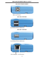
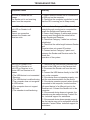
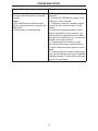
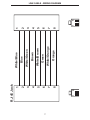
®
Mini USB
Extender
EXT-USB-MINI
USER MANUAL
www.gefen.com
ASKING FOR ASSISTANCE
Technical Support:
Telephone
(818) 772-9100
(800) 545-6900
Fax
(818) 772-9120
Technical Support Hours:
8:00 AM to 5:00 PM Monday thru Friday PST
Write To:
Gefen Inc.
c/o Customer Service
20600 Nordhoff St.
Chatsworth, CA 91311
[email protected]
www.gefen.com
Notice
Gefen Inc. reserves the right to make changes in the hardware, packaging and any
accompanying documentation without prior written notice.
Mini USB Extender is a trademark of Gefen Inc.
ExtremeUSB is a trademark of Gefen Inc.
All trademarks are the property of their respective owners.
Rev X1
© 2010 Gefen Inc., All Rights Reserved
TABLE OF CONTENTS
1
Introduction
2
Operation Notes
3
USB Series Installation
4
Mini USB Extender Panel Layout
5
Troubleshooting
6
Troubleshooting
7
Link Cable Diagram
8
Warranty
INTRODUCTION
Thank you for purchasing the ex•tend•it Mini USB Extender Series. Incorporating
ExtremeUSB, the new Mini USB Extender model allows users the benefits of USB
technology beyond the desktop, extending your computer keyboard, mouse, trackball,
and any USB device up to 150 feet away from the location of your Macintosh or PC.
The Mini USB Extender system consists of two units: the Mini USB Extender Sender
resides next to the host computer, and the Mini USB Extender Receiver resides next to
the extended USB devices.
The Mini USB Extender signal controls the keyboard, mouse, trackball and all other
USB devices by buffering the USB signal through the send and receive line drivers and
the signal is extended by using standard Category 5 (CAT-5) cabling.
You can connect additional Mini USB Extenders to the same computer, allowing you to
access the computer from multiple locations up to 150 feet apart.
There are two versions of the Mini USB Extender, one is the Mini USB-2 and the other
is the Mini USB-1. The Mini USB-2 has a two port USB hub built in. The Mini USB-1 has
a single port USB hub built in.
Product Contents
(1) Mini USB Sender
(1) Mini USB Receiver
(1) Manual
(1) USB cable 6ft (A-B)
1
OPERATION NOTES
READ THESE NOTES BEFORE INSTALLING OR
OPERATING THE MINI USB EXTENDER SYSTEM.
* The Mini USB Extender sender and receiver were designed to operate on USB type
computers. DO NOT attempt to use this equipment with any other type of device.
* Use the computer's USB port when using a local keyboard that is not extended with
the Mini USB Extender sender unit.
* Only dedicated Category 5 UTP type cable (CAT-5) is recommended for this
application (pin to pin).
* The length of cable used to connect the Mini USB Extender sender unit to the Mini
USB Extender receiver unit MUST NOT EXCEED 150 feet.
2
MINI USB EXTENDER SERIES INSTALLATION
1. Place the Mini USB Extender receiver unit close to the USB devices at the remote
end.
2. Connect the USB devices to the Mini USB Extender receiver unit
3. Place the Mini USB Extender sender unit close to the host computer.
4. Connect the Mini USB Extender sender unit to the Mini USB Extender receiver unit
using the desired length of CAT5 cable
6. Connect the Mini USB Extender sender unit to the host computer using the USB
cable supplied with the unit . This connection should be made last.
3
MINI USB EXTENDER PANELS LAYOUT
MINI USB EXTENDER SENDER
USB In from computer
MINI USB-2 RECEIVER
2 port USB Hub connects to USB devices
MINI USB-1 RECEIVER
1 port USB Hub connects to USB devices
Device LED (green) Link LED (yellow)
4
TROUBLESHOOTING
Symptoms/Cause
Remedy
All LEDs on Sender are off.
Cause:
The Sender unit is not receiving
power from the computer
1. Ensure that the Sender unit is connected to
a USB port on the computer
2. Check that the computer is switched on and
that the OS is running (not in Sleep mode).
Host LED on Sender is on;
Link LED on Sender is off.
Cause:
There is no connection
between the Sender and
Receiver units.
1. Ensure that a Category 5 UTP cable with
straight-through conductors is connected between the Sender and Receiver units.
2. Ensure that Category 5 cables and connectors are used throughout the entire link between Sender and Receiver.
3. Check that Category 3 cable has not been
substituted.
4. Check that the cable length between Sender
and
Receiver does not exceed 50 metres.
5. Connect a short Category 5 patch cord
between the Sender and Receiver units. Recheck the
operation of the system.
Link LED on Sender is on;
Host LED on Sender is on.
Link LED on Receiver is on;
Device LED on Receiver is off.
Cause:
a) The USB device is not connected
to Receiver.
b) The USB device is malfunctioning.
c) The computer does not recognise
the USB device.
d) The computer does not support
USB hubs.
e) The extender is malfunctioning.
1. Check that the USB device is securely connected to the USB port on the Receiver unit.
2. Disconnect the Sender unit from the computer.
3. Connect the USB device directly to the USB
port on the computer.
4. If the device does not operate properly, consult the user documentation for the device.
5. If the device operates properly when directly
connected to the computer, connect another
full speed device (of a different type) to the
Receiver unit. Connect the Sender unit to the
computer.
6. If the second device does not operate, the
extender may be malfunctioning. Contact Gefen technical support for assistance.
7. If the second device does operate properly,
the first device may not be compatible with the
extender. Contact Gefen technical support for
assistance.
5
TROUBLESHOOTING
Symptom/Cause
Remedies
All LEDs on both Sender and Receiver
are on but the device does not operate
correctly
Cause:
a) The USB device is malfunctioning.
b) The computer does not recognise the
USB device.
c) The extender is malfunctioning.
1. Disconnect the Sender unit from the
computer.
2. Connect the USB device directly to the
USB port on the computer.
3. If the device does not operate properly,
consult the user documentation for the
device.
4. If the device operates properly when
directly connected to the computer, connect another full speed device (of a different type) to the Receiver unit. Connect the
Sender unit to the computer.
5. If the second device does not operate, the extender may be malfunctioning.
Contact Gefen technical support for assistance.
6. If the second device does operate properly, the first device may not be compatible
with the extender. Contact Gefen technical
support for assistance.
6
7
1
8
8
7
6
5
4
3
2
1
RJ-45 Jack
Orange
White/Orange
Green
White/Brown
Brown
White/Green
Blue
White/Blue
8
7
6
5
4
3
2
1
1
8
LINK CABLE - WIRING DIAGRAM
WARRANTY
Gefen warrants the equipment it manufactures to be free from defects in material
and workmanship.
If equipment fails because of such defects and Gefen is notified within two (2)
years from the date of shipment, Gefen will, at its option, repair or replace the
equipment, provided that the equipment has not been subjected to mechanical,
electrical, or other abuse or modifications. Equipment that fails under conditions
other than those covered will be repaired at the current price of parts and labor in
effect at the time of repair. Such repairs are warranted for ninety (90) days from
the day of reshipment to the Buyer.
This warranty is in lieu of all other warranties expressed or implied, including
without limitation, any implied warranty or merchantability or fitness for any
particular purpose, all of which are expressly disclaimed.
1.
Proof of sale may be required in order to claim warranty.
2.
Customers outside the US are responsible for shipping charges to and from
Gefen.
3.
Copper cables are limited to a 30 day warranty and cables must be in their
original condition.
The information in this manual has been carefully checked and is believed to
be accurate. However, Gefen assumes no responsibility for any inaccuracies
that may be contained in this manual. In no event will Gefen be liable for
direct, indirect, special, incidental, or consequential damages resulting from
any defect or omission in this manual, even if advised of the possibility of such
damages. The technical information contained herein regarding the features and
specifications is subject to change without notice.
For the latest warranty coverage information, please visit Gefen’s Warranty web
page at http://www.gefen.com/kvm/aboutus/warranty.jsp
PRODUCT REGISTRATION
Please register your product online by visiting Gefen’s web site at
http://www.gefen.com/kvm/Registry/Registration.jsp
8
*MA-usb-mini*
Rev X1
20600 Nordhoff St., Chatsworth CA 91311
1-800-545-6900
818-772-9100
www.gefen.com
fax: 818-772-9120
[email protected]