1
CBX800 INSTALLATION MANUAL
INPUTS
The two optocoupled polarity insensitive inputs, Input 1 (External Trigger Input) and Input 2, a generic input,
available on the CBX800 spring clamp terminal blocks, are managed by the reader connected to the 25-pin
connector.
These inputs are optocoupled and can be driven by both NPN and PNP type commands.
Polarity insensitive inputs assure full functionality even if pins A and B are exchanged.
NOTE
External Trigger Input (Input 1)
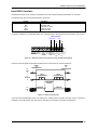
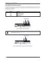
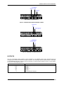
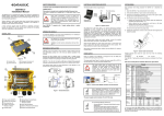
The connections are indicated in the following diagram:
Pinout
+V
I1A
I1B
-V
Function
Power Source - External Trigger
External Trigger A (polarity insensitive)
External Trigger B (polarity insensitive)
Power Reference - External Trigger
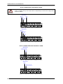
EXTERNAL TRIGGER INPUT CONNECTIONS USING CBX800 POWER
Power is available directly to the Input Device, independently from the Power Supply Switch
inside the CBX800.
CAUTION
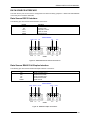
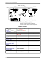
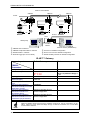
PH-1 Photocell (PNP)
(brown)
(black)
(blue)
Figure 27 – PH-1 External Trigger Using CBX800 Power
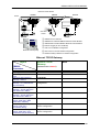
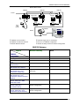
NPN Photocell
Power to
Photocell
Input
Signal
Photocell
Reference
Figure 28 - NPN External Trigger Using CBX800 Power
21