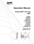
1
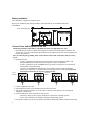
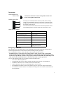
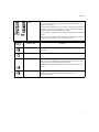
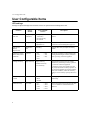
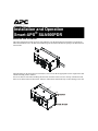
Installation and Operation Smart-UPS® SUA500PDR Mount the UPS on DIN Rail This unit is designed to mount on a heavy duty DIN rail or on the back panel of an enclosure. For details on DIN rail installation refer to the DIN rail installation guide included in the DIN rail package. The DIN rail kit is not included. su o0 74 8a When mounting on the back panel of an enclosure, select screws that are appropriate for the weight of this unit and the mounting surface material. Six screws must be used when mounting this unit in an enclosure. Three screws in the top of the bracket and three screws in the bottom of the bracket. Failure to follow these instructions may result in damage to the unit. Battery Installation The UPS battery is shipped in a separate carton. Refer to the installation guide included with the replacement battery for installation instructions. Front Panel 120 V model depicted. 8 7 6 5 4 3 2 1 NO ON CO M BATTERY NC NO LOW CO M BATTERY NC EPO COM EPO Test PUSH TO RESET INPUT OUTPUT GROUND NEUTRAL LINE N L 230V~ 50/60Hz, 500VA 325W, 2.7A MAX GROUND NEUTRAL N LINE suo0746a 208/220-240V~ 50/60Hz, 7A MAX L Connect Power and Equipment to the UPS Hardwiring should be performed by a qualified electrician. Use appropriate size wires. 1. The UPS features a transient voltage surge-suppression (TVSS) screw located on the front panel. The TVSS screw is used for connecting the ground lead on surge suppression devices such as telephone and network line protectors. Prior to connecting the grounding cable, ensure that the UPS is NOT connected to utility or battery power. 2. Hardwire the UPS. – In 230 V applications the UPS must be protected with a circuit breaker that complies with European standards for branch rated protection per the country of installation. – In 208 V applications, the SUA500PDRI must be protected by a dual pole, 10 A branch rated circuit breaker with UL489 rating. – The 120 V SUA500PDR has supplementary circuit breaker protection. The unit should be protected by a single pole, 15 A branch rated circuit breaker with a UL489 rating. Ensure that the branch circuit breaker is off prior to wiring the unit. 120 V models INPUT 208/230 V models OUTPUT NEUTRAL LINE NEUTRAL LINE N L N L INPUT L2/N OUTPUT L1 L2/N L1 3. Connect equipment to the UPS. 4. Add optional accessories to the SmartSlot located on the front panel. 5. Turn on all connected equipment. To use the UPS as a master on/off switch, be sure all connected equipment is switched on. 6. Press the Test button on the front panel to start the UPS. – The battery charges to 90% capacity during the first four hours of normal operation. – Do not expect full battery run capability during this initial charge period. 7. For optimal computer system security, install PowerChute monitoring software included with the UPS. 2 Connectors Communication Port A standard serial interface cable is incompatible with the UPS. Use the cable supplied with the unit. SERIAL PORT Contact Closure Port 8 7 6 5 4 3 2 1 The relays are connected from the common (COM) to the normally closed (NC) pins.When the unit enters a low battery or on battery state, the appropriate relay will transition and connect the common (COM) to the normally open (NO) pin. NO ON COM BATTERY NC NO LOW COM BATTERY NC EPO COM EPO The Contact Closure Port connection will automatically disable when a Network Management Card or the Serial Port connection are used. Output Contact Ratings: Parameter Value nominal switching capacity 1 A @ 30 VDC maximum switching power 30 W maximum switching voltage 60 VDC maximum switching current 2 ADC maximum carrying current 2 ADC surge ratings 2 kV per Bellcore TA-NWT-001089 1.5 kV per FCC part 68 Emergency Power Off The emergency power off (EPO) feature is user configurable. EPO provides immediate de-energizing of connected equipment from a remote location, without switching to battery operation. Use a normally-open contact to connect the EPO COM terminal to the EPO terminal. The EPO interface is a Safety Extra Low Voltage (SELV) circuit. Connect it only to other SELV circuits. The EPO interface monitors circuits that have no determined voltage potential. Such closure circuits may be provided by a switch or relay properly isolated from the utility. To avoid damage to the UPS, do not connect the EPO interface to any circuit other than a closure type circuit. Use one of the following cable types to connect the UPS to the EPO switch. • • • • • • CL2: Class 2 cable for general use. CL2P: Plenum cable for use in ducts, plenums, and other spaces used for environmental air. CL2R: Riser cable for use in a vertical run in a floor-to-floor shaft. CLEX: Limited use cable for use in dwellings and for use in raceways. For installation in Canada: Use only CSA certified, type ELC (extra-low voltage control cable). For installation in other countries: Use standard low-voltage cable in accordance with national and local regulations. 3 Operation Operation INPUT 208/220-240V~ 50/60Hz, 7A MAX GROUND 208/230 V models Test NEUTRAL LINE L INPUT OUTPUT 230V~ 50/60Hz, 500VA 325W, 2.7A MAX GROUND NEUTRAL N OUTPUT 208/220-240V~ 50/60Hz, 7A MAX 230V~ 50/60Hz, 500VA 325W, 2.7A MAX L2/N L2/N LINE L L1 L1 suo0745a N Test suo0745b UPS Display Panel 120 V models Display Panel Indicators and Function Buttons Indicator LED Indicator Title Description On-Line The UPS is supplying utility power to the connected equipment (see Troubleshooting). AVR Trim The UPS is compensating for a high utility voltage (see Troubleshooting). AVR Boost The UPS is compensating for a low utility voltage (see Troubleshooting). On Battery The UPS is supplying battery power to the connected equipment. Overload The connected equipment is drawing more than the UPS power rating allows (see Troubleshooting). Replace Battery/Battery The battery is disconnected or must be replaced (see Troubleshooting). Disconnected 4 Operation Diagnostic Utility Voltage Battery Charge Feature Button Feature Title Function Power On Press this button to turn on the UPS. Continue reading for additional capabilities. Power Off Press this button to turn off the UPS. Self-Test Automatic: The UPS performs a self-test automatically when turned on, and every two weeks thereafter (by default). During the self-test, the UPS briefly operates the connected equipment on battery. Test Manual: Press and hold the Test button for a few seconds to initiate the self-test. Test Cold Start Test The UPS has a diagnostic feature that indicates the utility voltage. The UPS starts a self-test as part of this procedure. The self-test does not affect the voltage display. Press and hold the Test button to view the utility voltage bar graph indicator. After a few seconds, this five-LED Battery Charge indicator on the right of the display panel will show the utility input voltage. Refer to the figure on the left for the voltage reading (values are not listed on the UPS). The indicator on the UPS shows the voltage is between the displayed value on the list and the next higher value (see Troubleshooting). When there is no utility power and the UPS is off, the cold start feature will switch the UPS and connected equipment onto battery power (see Troubleshooting). 5 User Configurable Items User Configurable Items UPS settings Settings are adjusted through PowerChute software or optional Network Management Card. Function 6 Factory Default User Selectable Choices Description Automatic Self-Test Every 14 days (336 hours) • Every 7 days (168 hours) • On start up only • No self-test Set the interval at which the UPS will execute a self-test. UPS ID UPS_IDEN Up to eight characters (alphanumeric) Uniquely identify the UPS (i.e. server name or location) for network management purposes. Date of Last Battery Replacement Manufacture Date mm/dd/yy Reset this date when you replace the battery module. Minimum Capacity Before Return from Shutdown 0 percent • • • • Voltage Sensitivity High sensitivity High sensitivity Medium sensitivity Low sensitivity The UPS detects and reacts to line voltage distortions by transferring to battery operation to protect the connected equipment. In situations of poor power quality, the UPS may frequently transfer to battery operation. If the connected equipment can operate normally under such conditions, reduce the sensitivity setting to conserve battery capacity and service life. Alarm Delay Control Enable • Enable • Mute • Disable Mute ongoing alarms or disable all alarms permanently. Shutdown Delay 90 seconds • • • • 0% 15% 30% 45% 0s 90 s 180 s 270 s • 60% • 75% • 90% • • • • 360 s 450 s 540 s 630 s Specify the percentage to which batteries will be charged following a low battery shutdown before powering connected equipment. Set the interval between the time when the UPS receives a shutdown command and actual shutdown. User Configurable Items Function Factory Default User Selectable Choices Description Low Battery Warning 2 minutes 2, 5, 8, 11, 14, 17, 20, 23 minutes PowerChute software interface provides automatic, unattended shutdown when approximately two minutes of battery operated run time remains. The low-battery warning beeps are continuous when two minutes of run time remain. Change the low battery warning interval setting to the time that the operating system or system software requires to safely shut down. Synchronized Turn-on Delay 0 seconds • • • • Specify the time the UPS will wait after the return of utility power before start up (to avoid branch circuit overload). High Transfer Point 120 V models: 127 VAC 230 V models: 253 VAC Low Transfer Point 120 V models: 106 VAC 230 V models: 208 VAC Output Voltage 230 V models 230 VAC 0s 60 s 120 s 180 s • • • • 240 s 300 s 360 s 420 s • 127 VAC • 130 VAC • 133 VAC • 136 VAC • 253 VAC • 257 VAC • 261 VAC • 265 VAC • 97 VAC • 100 VAC • 103 VAC • 106 VAC • 196 VAC • 200 VAC • 204 VAC • 208 VAC • 220 VAC • 230 VAC • 240 VAC To avoid unnecessary use of the battery where utility voltage is chronically high, set the high transfer point higher if the connected equipment can tolerate this condition. To avoid unnecessary use of the battery where utility voltage is chronically low, set the low transfer point lower if the connected equipment can tolerate this condition. The SUA500PDRI ships ready for 230 V sources. When operating the UPS in 208 V applications, the UPS low transfer voltage settings are adjusted through PowerChute software or the Network Management Card. The proper setting for low transfer voltage is 196 V. Refer to the PowerChute user guide or the Network Management Card instructions for setting adjustment details. 230 V models only: Sets the output voltage of the UPS while operating on battery. 7 Storage, Maintenance, Transport Storage, Maintenance, Transport Storage Store the UPS covered in a cool, dry location with the batteries fully charged. At 5° to 86° F (–15° to 30° C), charge the UPS battery every six months. At 86° to 113° F (30° to 45° C), charge the UPS battery every three months. Replacing the Battery Module This UPS uses a replaceable, hot-swappable battery module. Replacement is a safe procedure, isolated from electrical hazards. You may leave the UPS and connected equipment on during the replacement procedure. Ensure battery replacement every 2-4 years. APCRBC135: Standard (40° C) battery APCRBC136: High Temperature (50° C) battery Once the batteries are disconnected the connected equipment is not protected from power outages. Refer to the appropriate replacement battery installation guide for battery module installation instructions. See your dealer for information on replacement battery modules. Be sure to deliver the spent battery(s) to a recycling facility or ship it to the address specified in the replacement battery literature. 8 Troubleshooting Troubleshooting Use this chart to solve minor installation and operation problems. Problem and/or Possible Cause Solution UPS will not turn on The battery is not connected properly. Check that the battery connector is fully engaged. Press the Test button once to power-up the UPS and connected equipment. Test button not pushed. The UPS is not connected to utility power supply. Check that the UPS is properly connected to utility power. UPS will not turn off The UPS is experiencing an internal fault Do not attempt to use the UPS. Unplug the UPS and have it serviced immediately. UPS beeps occasionally Normal UPS operation when running on battery. None: The UPS is protecting the connected equipment. Press the Test button to silence this alarm. UPS is not providing expected backup time The UPS battery(s) are weak due to a recent power outage or battery(s) are near the end of their service life. Charge the battery(s). Batteries require recharging after extended outages. Batteries can wear faster when put into service often or when operated at elevated temperatures. If the battery(s) are near the end of their service life, consider replacing the battery(s) even if the replace battery LED is not yet illuminated. Left half, Right half, or Center section of front panel is flashing The UPS is experiencing an internal fault. Do not attempt to use the UPS. Unplug the UPS and have it serviced immediately. All LEDs are illuminated and the UPS emits a constant beeping The UPS is experiencing an internal fault. Do not attempt to use the UPS. Unplug the UPS and have it serviced immediately. Front panel LEDs flash sequentially The UPS has been shut down remotely through software or an optional accessory card. None: The UPS will restart automatically when utility power returns. 9 Troubleshooting Problem and/or Possible Cause Solution All LEDs are off and the UPS is wired to input utility power The UPS is shut down or the battery is discharged from an extended outage. None: The UPS will restart automatically when utility power is restored and the battery has a sufficient charge. The Overload LED is illuminated and the UPS emits a sustained alarm tone The UPS is overloaded. The connected equipment exceeds the specified “maximum load” as defined in Specifications listed on the rating label located on the UPS. The alarm remains on until the overload is removed. Disconnect nonessential equipment from the UPS to eliminate the overload condition. The UPS continues to supply power as long as it is online and the circuit breaker does not trip; the UPS will not provide power from batteries in the event of a utility voltage interruption. The Replace Battery/Battery Disconnected LED is illuminated The Replace Battery/Battery Disconnected LED flashes and a short beep is emitted every two seconds to indicate the battery is disconnected. Check that the battery connectors are fully engaged. Weak battery Allow the battery to recharge for 24 hours and perform a self-test. If the problem persists after recharging, replace the battery. Failure of a battery self-test: Replace Battery/Battery Disconnected LED illuminates and the UPS emits short beeps for one minute. The UPS repeats the alarm every five hours. Allow the battery to recharge for 24 hours. Perform the self-test procedure to confirm the replace battery condition. The alarm stops and the LED clears if the battery passes the self-test. If the battery fails again, it must be replaced. The connected equipment is unaffected. The input circuit breaker trips The connected equipment exceeds the specified “maximum load” as defined in Specifications listed on the rating label located on the UPS. Unplug all nonessential equipment from the UPS. Reset the circuit breaker. The AVR Boost or AVR Trim LEDs are illuminated The system is experiencing very high or low utility voltage. 10 Have a qualified service personnel check your facility for electrical problems. If the problem persists, contact the utility company for further assistance. Troubleshooting Problem and/or Possible Cause Solution There is no utility power There is no utility power and the UPS is off Use the cold start feature to supply power to the connected equipment from the UPS battery(s). Press and hold the Test button. The unit will emit two beeps, one short beep and one long beep. Release the button during the second beep. UPS operates on battery although line voltage exists The UPS input circuit breaker trips. Unplug all nonessential equipment from the UPS. Reset the circuit breaker. Your system is experiencing very high, low or distorted line voltage. Move the UPS to a different outlet on a different circuit: Inexpensive fuel powered generators may distort the voltage. Test the input voltage with the utility voltage display, (see Operation). If acceptable to the connected equipment, reduce the UPS sensitivity. Battery Charge and Load LEDs flash simultaneously The UPS has shut down The internal temperature of the UPS has exceeded the allowable threshold for safe operation. Check that the room temperature is within the specified limits for operation. Check that the UPS is properly installed, allowing for adequate ventilation. Allow the UPS to cool down. Restart the UPS. Diagnostic utility voltage All five LEDs are illuminated. The line voltage is extremely high and should be checked by an electrician. There is no LED illumination. If the UPS is plugged into a properly functioning utility power outlet, the line voltage is extremely low and should be checked by an electrician. On-Line LED There is no LED illumination. The UPS is running on battery, or it must be turned on. The LED is blinking. The UPS is running an internal self-test. Software/Network integration problems Network Management Card difficulties. Refer to the Network Management Card user guide on the CD shipped with the Network Management Card. Communication problems between the UPS and PowerChute software. Ensure the correct communication cable (940-1524D) is being used. Refer to the PowerChute user manual on the CD shipped with the software. 11 Service Service If the unit requires service, do not return it to the dealer. Follow these steps: 1. Review the Troubleshooting section of the manual to eliminate common problems. 2. If the problem persists, contact APC Customer Support through the APC Web site, www.apc.com. a. Note the model number and serial number and the date of purchase. The model and serial numbers are located on the rear panel of the unit and are available through the LCD display on select models. b. Call APC Customer Support and a technician will attempt to solve the problem over the phone. If this is not possible, the technician will issue a Returned Material Authorization Number (RMA#). c. If the unit is under warranty, the repairs are free. d. Service procedures and returns may vary internationally. Refer to the APC Web site for country specific instructions. 3. Pack the unit properly to avoid damage in transit. Never use foam beads for packaging. Damage sustained in transit is not covered under warranty. a. Always DISCONNECT THE UPS BATTERY before shipping in compliance with U.S. Department of Transportation (DOT) and IATA regulations. The battery may remain in the unit. b. Internal batteries may remain connected in the XLBP during shipment, if applicable, not all units have XLBPs. 4. Write the RMA# provided by Customer Support on the outside of the package. 5. Return the unit by insured, pre-paid carrier to the address provided by Customer Support. Transport the unit 1. Shut down and disconnect all connected equipment. 2. Disconnect the unit from utility power. 3. Disconnect all internal and external batteries (if applicable). 4. Follow the shipping instructions outlined in the Service section of this manual. APC Worldwide Customer Support Customer support for this or any other APC product is available at no charge in any of the following ways: • Visit the APC Web site to access documents in the APC Knowledge Base and to submit customer support requests. – www.apc.com (Corporate Headquarters) Connect to localized APC Web sites for specific countries, each of which provides customer support information. – www.apc.com/support/ Global support searching APC Knowledge Base and using e-support. • Contact the APC Customer Support Center by telephone or e-mail. – Local, country-specific centers: go to www.apc.com/support/contact for contact information. For information on how to obtain local customer support, contact the APC representative or other distributors from whom you purchased your APC product. 12 Two-Year Factory Warranty Two-Year Factory Warranty This warranty applies only to the products you purchase for your use in accordance with this manual. Terms of warranty APC warrants its products to be free from defects in materials and workmanship for a period of two years from the date of purchase. APC will repair or replace defective products covered by this warranty. This warranty does not apply to equipment that has been damaged by accident, negligence or misapplication or has been altered or modified in any way. Repair or replacement of a defective product or part thereof does not extend the original warranty period. Any parts furnished under this warranty may be new or factory-remanufactured. Non-transferable warranty This warranty extends only to the original purchaser who must have properly registered the product. The product may be registered at the APC Web site, www.apc.com. Exclusions APC shall not be liable under the warranty if its testing and examination disclose that the alleged defect in the product does not exist or was caused by end user’s or any third person’s misuse, negligence, improper installation or testing. Further, APC shall not be liable under the warranty for unauthorized attempts to repair or modify wrong or inadequate electrical voltage or connection, inappropriate on-site operation conditions, corrosive atmosphere, repair, installation, exposure to the elements, Acts of God, fire, theft, or installation contrary to APC recommendations or specifications or in any event if the APC serial number has been altered, defaced, or removed, or any other cause beyond the range of the intended use. THERE ARE NO WARRANTIES, EXPRESS OR IMPLIED, BY OPERATION OF LAW OR OTHERWISE, OF PRODUCTS SOLD, SERVICED OR FURNISHED UNDER THIS AGREEMENT OR IN CONNECTION HEREWITH. APC DISCLAIMS ALL IMPLIED WARRANTIES OF MERCHANTABILITY, SATISFACTION AND FITNESS FOR A PARTICULAR PURPOSE. APC EXPRESS WARRANTIES WILL NOT BE ENLARGED, DIMINISHED, OR AFFECTED BY AND NO OBLIGATION OR LIABILITY WILL ARISE OUT OF, APC RENDERING OF TECHNICAL OR OTHER ADVICE OR SERVICE IN CONNECTION WITH THE PRODUCTS. THE FOREGOING WARRANTIES AND REMEDIES ARE EXCLUSIVE AND IN LIEU OF ALL OTHER WARRANTIES AND REMEDIES. THE WARRANTIES SET FORTH ABOVE CONSTITUTE APC’S SOLE LIABILITY AND PURCHASER’S EXCLUSIVE REMEDY FOR ANY BREACH OF SUCH WARRANTIES. APC WARRANTIES EXTEND ONLY TO PURCHASER AND ARE NOT EXTENDED TO ANY THIRD PARTIES. IN NO EVENT SHALL APC, ITS OFFICERS, DIRECTORS, AFFILIATES OR EMPLOYEES BE LIABLE FOR ANY FORM OF INDIRECT, SPECIAL, CONSEQUENTIAL OR PUNITIVE DAMAGES, ARISING OUT OF THE USE, SERVICE OR INSTALLATION, OF THE PRODUCTS, WHETHER SUCH DAMAGES ARISE IN CONTRACT OR TORT, IRRESPECTIVE OF FAULT, NEGLIGENCE OR STRICT LIABILITY OR WHETHER APC HAS BEEN ADVISED IN ADVANCE OF THE POSSIBILITY OF SUCH DAMAGES. SPECIFICALLY, APC IS NOT LIABLE FOR ANY COSTS, SUCH AS LOST PROFITS OR REVENUE, LOSS OF EQUIPMENT, LOSS OF USE OF EQUIPMENT, LOSS OF SOFTWARE, LOSS OF DATA, COSTS OF SUBSTITUENTS, CLAIMS BY THIRD PARTIES, OR OTHERWISE. NO SALESMAN, EMPLOYEE OR AGENT OF APC IS AUTHORIZED TO ADD TO OR VARY THE TERMS OF THIS WARRANTY. WARRANTY TERMS MAY BE MODIFIED, IF AT ALL, ONLY IN WRITING SIGNED BY AN APC OFFICER AND LEGAL DEPARTMENT. Warranty claims Customers with warranty claims issues may access the APC customer support network through the Support page of the APC Web site, www.apc.com/support. Select your country from the country selection pull-down menu at the top of the Web page. Select the Support tab to obtain contact information for customer support in your region. 13 © 2011 APC by Schneider Electric. APC, the APC logo, Smart-UPS and PowerChute are owned by Schneider Electric Industries S.A.S., American Power Conversion Corporation, or their affiliated companies. All other trademarks are property of their respective owners. 990-4412 06/2011