1
QUICK INSTALLATION GUIDE
17” LCD Tray
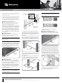
5 Attaching the cable channel
Thread the cables that exit from the end of the CMA arm
through the cable channel bracket before mounting the
bracket to the unused center hole of the left side rack rail.
LED activated, simultaneously press the Fn key and the
desired number key. For example, press Fn + O to type
the number 6.
Sales Level Model designation. The designation that is
referenced in the certifications reports and/or certificates
are printed on the label applied to this product.
Both the Fn LED and the Num LED must be lit in order for
the numeric keypad to operate.
DANGEROUS VOLTAGE
For longer numeric entries, press Fn + F11 to initiate a
continuously active numeric keypad.
Cable
Channel
LCD Controls
Description
Turns the 17” LCD Tray on
or off. A green LED indicates normal operation.
Auto
Auto-synchronizes and
scales down display to
factory presets.
NOTE: The AC inlet is the main power disconnect.
Exit
Exits the OSD or returns
to previous menu.
INSTRUCTIONS
Right arrow
Selects the function to be
adjusted and increases
values of settings.
Left arrow
Decreases values of
settings.
Controls the brightness of
backlight lamps without
using the OSD menu.
Menu
Connecting the 17” LCD Tray
Connect the video, keyboard, and mouse connectors to
either a server or a console switch in the rack cabinet.
Connect the power cord to a properly grounded electrical
outlet or power distribution unit (PDU).
Displays the OSD menu
and moves selector on the
OSD menu.
6
Fully extend the LCD Tray from the front of the rack
cabinet, and then route the cables within the rack cabinet,
securing them with cable straps along the way. Do not
coil the cables.
To minimize the electrical interference from the video
cable, arrange the cable in figure-eight loops. Secure the
cable in the middle with a cable strap.
NOTE: If necessary, the monitor and keyboard can
be secured inside the rack cabinet using the two
thumbscrews on the front of the LCD Tray.
Keyboard Controls
The 17” LCD Tray keyboard with integrated pointing
device is designed for use with any USB, PS/2 or
compatible computer. Both the pointing device and
keyboard use the host computer’s operating system
generic software drivers and therefore do not require
custom software drivers to be installed on the host
computer prior to use.
USB Pass-Through
Connect the passive cable (located on the front lip of the
LCD Tray) to either a KVM switch or a server. This plug
and play cable allows USB 2.0 devices to connect to the
target appliance. No custom drivers are required for this
feature.
Numeric Keypad
The number keys and letter keys share space on the
keyboard. To activate the numeric keypad, press the
Num Lock key to turn on the Num LED. With the Num
This symbol is intended to alert the user to the
presence of uninsulated dangerous voltage
within the product’s enclosure that may be of sufficient
magnitude to constitute a risk of electric shock to
persons. Never remove a cover on a power supply or any
part that has this label attached.
LCD TRAY SAFETY AND
EMC NOTIFICATIONS
USA
WARNING: Changes or modifications to this unit not
expressly approved by the party responsible for compliance
could void the user’s authority to operate the equipment.
NOTE: This equipment has been tested and found to
comply with the limits for a Class A digital device, pursuant
to Part 15 of the FCC Rules. These limits are designed to
provide reasonable protection against harmful interference
when the equipment is operated in a commercial environment. This equipment generates, uses and can radiate
radio frequency energy and, if not installed and used in
accordance with the instruction manual, may cause harmful
interference to radio communications. Operation of this
equipment in a residential area is likely to cause harmful
interference in which case the user will be required to
correct the interference at his own expense.
Japanese Approval
This symbol is intended to alert the user to the
presence of important operating and maintenance
(servicing) instructions.
WARNING: To reduce the risk of electric shock or damage
to your equipment:
–Do not connect or disconnect any cables or perform
installation, maintenance, or reconfiguration of this
product during an electrical storm.
–Connect all power cords to a properly wired and
grounded electrical outlet.
–Connect any equipment that will be attached to this
product to properly wired outlets.
–When possible, only use one hand to connect or
disconnect signal cables.
–Never turn on any equipment when there is evidence
of fire, water, or structural damage.
–Disconnect the attached power cords, networks,
telecommunications systems and modems before you
open the device covers, unless instructed otherwise in
the installation and configuration procedures.
Rack and Wall Mount Safety Considerations
• Elevated Ambient Temperature: If installed in a closed
rack assembly, the operation temperature of the
rack environment may be greater than room ambient.
Use care not to exceed the rated maximum ambient
temperature of the appliance.
• Reduced Air Flow: Installation of the equipment in
a rack should be such that the amount of airflow
required for safe operation of the equipment is not
compromised.
• Mechanical Loading: Mounting of the equipment in the
rack should be such that a hazardous condition is not
achieved due to uneven mechanical loading.
Safety and EMC Approvals and Markings
CE, C-TICK, FCC, GOST, GS/INNOVA, UL, ULC, VCCI
• Circuit Overloading: Consideration should be given
to the connection of the equipment to the supply
circuit and the effect that overloading of circuits
might have on overcurrent protection and supply
wiring. Consider equipment nameplate ratings for
maximum current.
Safety Precautions
Certifications for this product are obtained under one or
more of the following designations: CMN (Certification
Model Number), MPN (Manufacturer’s Part Number) or
• Reliable Earthing: Reliable earthing of rack mounted
equipment should be maintained. Pay particular
attention to supply connections other than direct
connections to the branch circuit (for example, use of
power strips).
To Contact Avocent Technical Support: Visit www.avocent.com Avocent and the Avocent logo are registered trademarks of Avocent Corporation or its affiliates in the U.S. and other countries. All other marks are the property of their respective owners. ©2009 Avocent Corporation.
590-980-501A