1
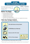
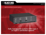
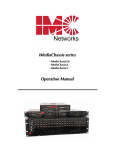
FiberLinX Installation Manual and User Reference Guide 19772 Pauling Foothill Ranch, CA 92610-2611 USA TEL: (949) 465-3000 FAX: (949) 465-3020 www.imcnetworks.com Document Number 50-80111-01 A0 February 2000 Preface This manual contains information to assist with installation and use of IMC Networks FiberLinX product line. For more information about IMC Networks products, please visit the IMC Networks Web site at www.imcnetworks.com. Disclaimer IMC Networks makes no warranties with respect to this document and disclaims any implied warranties of merchantability or fitness for a particular purpose. IMC Networks assumes no responsibility for any errors that may appear in this document or for incidental consequential damages in connection with the performance or use of this material. This document contains proprietary information which is protected by copyright. No part may be reproduced in any way without prior consent of IMC Networks. Copyright © 1999-2000 IMC Networks. All rights reserved. Trademarks FiberLinX is a trademark of IMC Networks. Other brands, product names or features may be trademarks and are the properties of their respective companies. Contents Chapter 1: Introduction About FiberLinX . . . . . . . . . . . . . . . . . . . . . . . . . . . . . . . . . . . . . . . .1.1 About FiberLinX Modules . . . . . . . . . . . . . . . . . . . . . . . . . . . . . . . . .1.2 How FiberLinX Works . . . . . . . . . . . . . . . . . . . . . . . . . . . . . . . . . . .1.2 Chapter 2: Hardware Installation Configuring FiberLinX Modules . . . . . . . . . . . . . . . . . . . . . . . . . . . . .2.1 Switches 1 & 2: Fiber Optic Type . . . . . . . . . . . . . . . . . . . . . .2.2 Switches 3 & 4: Selecting Duplex Mode . . . . . . . . . . . . . . . . .2.2 Switches 5 & 6: SNMP Management Traffic . . . . . . . . . . . . . .2.2 Switches 7 & 8: Configuring FiberLinX as a Host, Remote or fielrStandalone Unit . . . . . . . . . . . . . . . . . . . . . . . . . . . . . . . . .2.3 FiberAlert . . . . . . . . . . . . . . . . . . . . . . . . . . . . . . . . . . . . . . . . . . . .2.3 Installing a FiberLinX Module . . . . . . . . . . . . . . . . . . . . . . . . . . . . . .2.4 Selecting a Twisted Pair Crossover/Pass-Through Connection . . . . . .2.5 LED Operation . . . . . . . . . . . . . . . . . . . . . . . . . . . . . . . . . . . . . . . .2.5 LEDs for the Fiber Data Port . . . . . . . . . . . . . . . . . . . . . . . . . .2.5 LEDs for the Twisted Pair Data Port . . . . . . . . . . . . . . . . . . . . .2.5 LEDs for the Twisted Pair Management Port . . . . . . . . . . . . . .2.5 DB-9 Serial Connector . . . . . . . . . . . . . . . . . . . . . . . . . . . . . . . . . .2.6 Chapter 3: Configuring and Managing FiberLinX Required Management Configuration Steps . . . . . . . . . . . . . . . . . . .3.1 Assigning IP Information to FiberLinX . . . . . . . . . . . . . . . . . . . . . . . .3.1 HUBCTRL 32 . . . . . . . . . . . . . . . . . . . . . . . . . . . . . . . . . . . . .3.2 Serial Port Configuration . . . . . . . . . . . . . . . . . . . . . . . . . . . . .3.2 About iView . . . . . . . . . . . . . . . . . . . . . . . . . . . . . . . . . . . . . . . . . . .3.2 System Requirements . . . . . . . . . . . . . . . . . . . . . . . . . . . . . . .3.3 Using iView To Manage FiberLinX . . . . . . . . . . . . . . . . . . . . . . . . . .3.3 If Using iView with HP OpenView . . . . . . . . . . . . . . . . . . . . . . . . . .3.3 If NOT using iView . . . . . . . . . . . . . . . . . . . . . . . . . . . . . . . . . . . . .3.4 Chapter 4: Application Examples Example 1: Direct Fiber Switch Connection from Central Site to Remote Site . . . . . . . . . . . . . . . . . . . . . . . .4.1 Example 2: Fiber Conversion and Remote Management Between Two Copper-Based Switches . . . . . . . . . .4.2 Example 3: Fiber Conversion and Highly Secure Remote Management Between Two Copper-Based Switches . . . . . . . . . .4.3 Chapter 5: Technical Specifications Fiber Optic Cleaning Guidelines . . . . . . . . . . . . . . . . . . . . . . . . . . .5.1 Electrostatic Discharge Precautions . . . . . . . . . . . . . . . . . . . . . . . . .5.1 Unit Specifications . . . . . . . . . . . . . . . . . . . . . . . . . . . . . . . . . . . . .5.2 Environmental . . . . . . . . . . . . . . . . . . . . . . . . . . . . . . . . . . . . .5.2 Power . . . . . . . . . . . . . . . . . . . . . . . . . . . . . . . . . . . . . . . . . . .5.2 Heat . . . . . . . . . . . . . . . . . . . . . . . . . . . . . . . . . . . . . . . . . . . .5.2 Fiber Optic . . . . . . . . . . . . . . . . . . . . . . . . . . . . . . . . . . . . . . .5.2 Chapter 6: General Information Technical Support . . . . . . . . . . . . . . . . . . . . . . . . . . . . . . . . . . . . . .6.1 Warranty . . . . . . . . . . . . . . . . . . . . . . . . . . . . . . . . . . . . . . . . . . . . .6.1 Federal Communications Commission Radio Frequency Interference Statement . . . . . . . . . . . . . . . . . . . . . . . . . . . . . . . .6.3 Appendix Assiging IP Information to FiberLinX Using Serial Port . . . . . . . . . . . .Ap.1 HUBCTRL32 Installation Instructions . . . . . . . . . . . . . . . . . . . . . . . .Ap.4 Chapter 1: Introduction About FiberLinX FiberLinX from IMC Networks is an IEEE 802.3 compliant, SNMPmanageable media converter/LAN extender/Ethernet bridge that can be managed remotely. FiberLinX is designed to convert between 10 Mbps Ethernet twisted pair (10Base-T) and 10 Mbps Ethernet (10Base-FL) singlemode or multi-mode fiber optic cabling. Each FiberLinX features the following three ports: 10Base-T data port 10Base-FL data port 10Base-T port specifically for SNMP traffic (i.e., the management port). NOTE: Although the Figure 1.1 FiberLinX Port Connections management port is designed to accept SNMP traffic, ANY port on the FiberLinX Module can be configured to serve as the SNMP management port. NOTE: The twisted pair management port is not designed to handle data traffic, and therefore should NOT serve as a redundant twisted pair port. The primary advantage of FiberLinX is that it allows the administrator to completely monitor and manage fiber traffic between switches and routers while remaining isolated from the remote (or customers) network. Figure 1.2 Example FiberLinX Installation 1.1 See Chapter 4 of this guide for more example FiberLinX installations. About FiberLinX Modules FiberLinX Modules can be installed into any IMC Networks PowerChassis/100-Series. The following versions of FiberLinX Modules are available: FiberLinX 10Base-T twisted pair and 10BaseFL 850 nm multi-mode fiber; includes two RJ-45 connectors and one pair ST or SC connectors. FiberLinX 1300 10Base-T twisted pair and 10Base-FL 1300 nm multi-mode fiber; includes two RJ-45 connectors and one pair ST or SC connectors. FiberLinX-SingleMode 10Base-T twisted pair and 10Base-FL 1300 nm single-mode fiber; includes two RJ-45 connectors and one pair ST or SC connectors. FiberLinX-SingleMode/PLUS as above with higher power budget. Figure 1.3 10 Mbps FiberLinX Module How FiberLinX Works Each port on the FiberLinX includes its own MAC Address. The movement of data from one port to another is accomplished via packet switching. The destination address of each Ethernet packet entering the FiberLinX is checked to determine whether it is a management packet or a downstream data packet, and is switched appropriately. Packets not addressed for management ports are sent through to the network. Similarly, management packets are switched internally to the management engine and are Figure 1.4 FiberLinX Packet Switching not forwarded. More information about how FiberLinX works can be found on the IMC Networks Web site at www.imcnetworks.com. 1.2 Chapter 2: Hardware Installation Installing a FiberLinX Module involves the following steps: 1) Configuring the FiberLinX Module via its eight-position Dip switch for the following: Half/Full Duplex setting (data ports only), designating the management traffic port, host/remote or standalone operation; l l l 2) Installation of a PowerChassis/100-Series chassis; 3) Installation of the FiberLinX Module into the above-mentioned PowerChassis; and, 4) Selecting a crossover or pass-through connection for the twisted pair data port. Configuring FiberLinX Modules FiberLinX Modules have an eight-position Dip switch, located at position S2 (shown below), for configuring the module. Figure 2.1 Dip Switch Location on FiberLinX (default settings shown) 2.1 The following table shows the function for each of the eight Dip switches on FiberLinX. Refer to the section on each feature for specific configuration information. FIBERLINX DIP SWITCH GUIDE Switch Feature 1 DO NOT CHANGE Varies 2 DO NOT CHANGE Varies 3 Enables Full-Duplex mode on the Fiber Data port OFF 4 Enables Full-Duplex mode on the Twisted Pair Data port OFF 5 Specifies from which port SNMP traffic is accepted ON 6 Specifies from which port SNMP traffic is accepted OFF 7 Configures FiberLinX as a Remote unit OFF 8 Configures FiberLinX as a Host unit OFF Default Switches 1 & 2: Fiber Optic Type These Dip switch settings are configured at the factory and should NOT be changed in the field. Switches 3 & 4: Selecting Duplex Mode Each data port on FiberLinX can operate in either Half-Duplex (HDX) or Full-Duplex (FDX) Mode. (NOTE: The Twisted Pair management port is ALWAYS Half-Duplex.) You will need to set the duplex mode of these ports depending on the capabilities of the connected hardware. FiberLinX is shipped from the factory with HDX selected on each data port (i.e., Dip switches 3 and 4 in the OFF position). Select FDX for the fiber data port by setting Dip switch 3 to ON. Select FDX for the twisted pair data port by setting Dip switch 4 to ON. Switches 5 & 6: SNMP Management Traffic Although FiberLinX provides a twisted pair port solely for management traffic, you can configure FiberLinX to accept SNMP management traffic from any of its three ports. There are four different ways you can configure FiberLinX to accept (or not accept) SNMP management traffic. Only one source for SNMP management traffic can be active at any time, and only the SNMP management traffic directed to the modules IP address will be accepted. FiberLinX is configured at the factory to accept SNMP management traffic from the twisted pair data port (i.e., Dip switch 5 ON, Dip switch 6 OFF). You can change this setting by adjusting Dip switches 5 and 6. The following table shows the switch settings for each configuration. 2.2 SNMP MANAGEMENT TRAFFIC DIP SWITCHES Switch 5 Switch 6 Result (Designated Mgmt. Port) OFF (none) Accepts no SNMP commands, even if directed to FiberLinX’s IP address. All SNMP traffic on the data ports is passed through. All traffic on the management port is discarded. ON OFF (TP mgmt. port) Accepts SNMP commands only from the management port. All SNMP traffic on the data ports is passed through. OFF ON OFF ON ON Accepts SNMP commands only in-band from the twisted pair data port. All traffic on the management port is discarded. (TP data port) DEFAULT All SNMP traffic on the fiber data port is passed through. Accepts SNMP commands only in-band from the fiber data port. All traffic on the management port is discarded. All SNMP traffic on the twisted pair data port is passed through. (FO data port) Switches 7 & 8: Configuring FiberLinX as a Host, Remote or Standalone Unit When two FiberLinX units are paired with one another, each FiberLinX unit can be configured to be either a Host unit or a Remote unit. As a Host, FiberLinX requests management information from any attached remote unit and displays that information, along with its own, upon SNMP query. As a Remote, FiberLinX will not respond to requests for management information from an attached unit. In single installation, the sole FiberLinX should be configured as standalone unit (factory default). Following is a table showing the Dip switch configurations for each setting. Please see Chapter 4 of this guide for possible installations and their related Host, Remote and standalone Dip switch settings. Configure FiberLinX to be a Host unit by setting Dip switch 8 to ON. Configure FiberLinX to be a Remote unit by setting Dip switch 7 to ON. HOST Switch 7 Switch 8 AND REMOTE DIP SWITCHES Result OFF OFF Standalone Configuration (no Host or Remote) DEFAULT ON OFF Remote Unit Configuration (Slave) OFF ON Host Unit Configuration (Master) FiberAlert Since media converters are a transparent link in a network, FiberLinX features FiberAlert, a troubleshooting feature that assists in pinpointing link faults between media conversion products. If a media converter is not 2.3 receiving a fiber link, FiberAlert disables the media converter's fiber transmitter, thus mirroring the link status of the opposite end of the fiber. Both fiber link LEDs on either side of the devices should extinguish, alerting you to the fault. NOTE: FiberAlert should only be activated on one side of a media conversion. More information on FiberAlert can be found on the IMC Networks Web site at www.imcnetworks.com/to-fa.htm. Installing a FiberLinX Module Once you configure a FiberLinX Module, it is ready to be installed in a chassis. You can install a FiberLinX Module into any IMC Networks PowerChassis/100-Series chassis (e.g., PowerChassis/101, etc.). FiberLinX Modules may be safely installed or removed with power on (i.e., FiberLinX Modules are hot-swappable). Please read the electrostatic discharge precautions on page 5.1 of this manual before proceeding NOTE: FiberLinX Modules should be installed into a PowerChassis only AFTER the PowerChassis has been installed. Please see the installation guide included with your chassis for assistance in installing the chassis. PowerChassis come with blank brackets covering the slots where the modules are to be installed. To install a FiberLinX Module, remove the blank bracket by loosening the screws located on the outside edges of the bracket. Slide the FiberLinX Module into the chassis until the module is seated securely in the connector. Secure the module to the chassis by tightening the captive screws. 2.4 Selecting a Crossover/Pass-Through Connection Once a FiberLinX is installed, you can select a crossover workstation or pass-through repeater/hub connection for the twisted pair data port. FiberLinXs twisted pair data port has one RJ-45 connector for a single shielded or unshielded twisted pair link segment and features a push-button switch, located next to the port, for selecting the type of connection. To select a pass-through connection on FiberLinX, simply press the pushbutton IN. A crossover connection is selected when the push-button is OUT. NOTE: If uncertain whether a crossover or pass-through connection is needed, set the switch to the position that makes the TP data port link LED glow. LED Operation FiberLinX features diagnostic LEDs for each port. The following illustration shows the location of the LEDs on FiberLinX. LEDs for the Fiber Data Port LED functions for the fiber data port are as follows: FDX Glows yellow when FDX is selected on port. ACT Blinks green when data is detected on the port. LNK Glows green when a link is established. FA Glows green when FiberAlert is enabled. LEDs for the Twisted Pair Data Port LED functions for the twisted pair data port are as follows: LNK Glows green when a link is established. FDX Glows yellow when FDX is selected on the port. LEDs for the Twisted Pair Management Port LED functions for the twisted pair management port are as follows: LNK Glows green when a link is established. FDX Glows yellow when FDX is selected on the port. FAR CPU Figure 2.2 UP Glows yellow when far end is detected. FiberLinX LEDs 2.5 FAR TP LINK SNMP TP ACT Glows green when a link is established on remote (far-end) TP data port. Blinks green with SNMP activity. Blinks green with TP activity. NOTE: The FAR CPU UP LED and the FAR TP LNK LED only function when two FiberLinX are connected to one another (i.e., Host and Remote). DB-9 Serial Connector FiberLinX features a DB-9 serial connector, located above the module name on the faceplate. This connector can be used as a serial port connection for assigning IP configuration information to FiberLinX. For more information on assigning IP information, please see Chapter 3 of this guide. For instructions, please see the Appendix of this guide. 2.6 Chapter 3: Configuring and Managing FiberLinX This chapter details the steps you must complete to configure and manage your FiberLinX. Required Management Configuration Steps In order for the installed FiberLinX to be managed using iView or another network management software (NMS) application, the following steps need to be completed: 1) Hardware installation of FiberLinX (see Chapter 2). 2) Assign IP information (i.e., IP address, subnet mask and, if desired, default gateway) to FiberLinX using either the units serial port or HUBCTRL32. (More on this later in this chapter.) 3) Installation of iView or another SNMP network management software package on the management PC. 4) Integration of IMC Networks MIB files into the SNMP management software. (NOTE: If using iView, this will be done for you automatically. Otherwise, refer to your NMSs documentation and see the section If NOT Using iView later in this chapter for integration assistance.) Assigning IP Information to FiberLinX In order to manage FiberLinX, it is first necessary to give it an IP address so that is accessible via SNMP. There are two ways to assign IP information to FiberLinX: using HUBCTRL32 (need Windows 98/NT) via the units serial port Besides assigning an IP address and subnet mask, both methods will also allow you to create community strings, assign access rights, send traps and more. However, HUBCTRL32 offers more options than the serial port method (e.g., you can select which traps to assign with HUBCTRL32). 3.1 HUBCTRL32 HUBCTRL32 (Hub Control 32) is an in-band configuration utility created by IMC Networks that lets users quickly and easily complete the first stages of SNMP configuration for IMC Networks SNMP-manageable devices. Tasks HUBCTRL32 can perform include: setting the IP address, subnet mask and default gateway; defining the community strings and SNMP traps; and setting PPP parameters for remote management. In addition to the above functions, HUBCTRL32 offers an authorized IP address system and access restriction to MIB groups supported by IMC Networks manageable devices. These extra layers of security are purely optional and do not effect SNMP compatibility in any way. HUBCTRL32 can also be used to upload new versions of the system software and new MIB information. It also offers diagnostic capabilities for faster resolution of technical support issues. HUBCTRL32 works with the following platforms: Windows NT Windows 98 HUBCTRL32 can be found on the iView CD, or you can download it from the IMC Networks Web site (www.imcnetworks.com/tech/ software.htm). For installation instructions, please see page Ap.4 in the Appendix of this guide. For information regarding the use of HUBCTRL32, refer to the HUBCTRL32 online help file. Serial Port Configuration The DB-9 serial port found on the FiberLinX faceplate may also be used to assign IP information to FiberLinX. For instructions, please see page Ap.1 in the Appendix of this guide. About iView TM iView is a cross-platform network management application for IMC Networks intelligent networking devices. It features a graphic user interface (GUI) and gives network managers the ability to monitor and control IMC Networks products from virtually any 32-bit Windows platform. iView can also function as a snap-in module for many SNMP applications. For more information about iView, visit www.imcnetworks.com/products/iview.htm. 3.2 System Requirements To run iView for FiberLinX, the management PC must be equipped with the following: 20 MB free disk space, 32 MB RAM as well as one of the following operating systems: TM Windows 95/98/NT (standalone or with OpenView) HP-UX and OpenView IBM AIX and NetView or OpenView Solaris and OpenView Please consult the iView CD for assistance in installing and launching iView for FiberLinX. Using iView To Manage FiberLinX iView for FiberLinX features a Module Detail Screen, the main viewing screen for iView for FiberLinX. Depending on whether you are managing a standalone unit or dual (Host/Remote) FiberLinX units, iViews displays and options will vary. From within iView for FiberLinX, you can use its virtual faceplate display(s) to remotely manage your FiberLinX unit(s). Note that within iView for FiberLinX, the only end-user configuration options are creating descriptions for the units and disabling/enabling ports (default on all ports is enabled). The rest of the functions are purely information-related. For a window-by-window guide to iView for FiberLinX, please consult the FiberLinX online help file (choose Start, Programs, IMC Networks, iView, FiberLinX Help, or use the Help menu within iView for FiberLinX). If Using iView with HP OpenView During the installation process, iView will ask if HP OpenView is installed on the management PC. Click Yes to integrate the appropriate files. You can also manually copy the file FLINX.REG into the appropriate OpenView resource file on the management PC (usually C:\openview\ resource\c). 3.3 Once in OpenView, highlight the FiberLinX icon and select the Tools, FiberLinX; OpenView will then launch iView. If NOT Using iView NOTE: Installation of SNMP software differs from one package to another. This section describes the steps required to integrate the IMC Networks agent with other management software. For installation details on the the management software being used, refer to the manufacturers documentation. The majority of management packages have a function known as MIB COMPILER. This function reads in the MIB information and converts it into machine-readable format. In order to successfully manage FiberLinX with your chosen application, the MIBs listed below need to be integrated into the management software: FLINX.MIB RFC1643.MIB Refer to the management software documentation regarding how MIBs are integrated into the software. NOTE: Although graphics are a desirable feature for viewing FiberLinX information, this same information can be seen by browsing the MIB information to which the management software has access. 3.4 Chapter 4: Application Examples FiberLinX can be used in many configurations based upon application, network architecture and management security requirements. The following are several examples of how you can use FiberLinX in your network. Example 1: Direct Fiber Switch Connection from Central to Remote Site To achieve remote management and monitoring capabilities, directly connect a FiberLinX to a fiber-based switch. All SNMP management traffic and data traffic goes straight into the switch at the Central site via the fiber port. SNMP management traffic is imbedded within the corporate network, but no management data passes to the Remote site. Configure FiberLinX to accept SNMP management traffic from the fiber port. In this application, FiberLinX is neither a Host nor Remote unit. The twisted pair management port on this FiberLinX is unused. EXAMPLE 1: DIP SWITCH SETTINGS Switch 5 ON Switch 6 ON 4.1 Switch 7 Switch 8 OFF OFF Example 2: Fiber Conversion and Remote Management Between Two Copper-Based Switches In this situation, configure the Central sites unit as a Host with management traffic through the twisted pair data port, and the Remote site's unit to accept management traffic through the fiber data port. Note that the twisted pair management ports on both FiberLinX remain unused. EXAMPLE 2: DIP SWITCH SETTINGS FiberLinX Switch 5 Switch 6 Switch 7 Switch 8 Central (Host) ON OFF OFF ON Remote ON ON ON OFF NOTE: You can access and manage the Remote sites FiberLinX directly in this configuration if you assign the unit an IP address. 4.2 Example 3: Fiber Conversion and Highly Secure Remote Management Between Two Copper-Based Switches For the highest level of management security, route SNMP management traffic completely away from the switch. Two FiberLinX units are also used in this configuration. The following illustration shows an external hub being used to maintain LAN separation. Configure the two FiberLinX units used in this example exactly as the ones in Example 2, except direct management traffic on the Central sites unit to the twisted pair management port. EXAMPLE 3: DIP SWITCH SETTINGS FiberLinX Switch 5 Switch 6 Switch 7 Switch 8 Central (Host) OFF ON OFF ON Remote ON ON ON OFF 4.3 4.4 Chapter 5: Technical Specifications Fiber Optic Cleaning Guidelines Fiber Optic transmitters and receivers are extremely susceptible to contamination by particles of dirt or dust which can obstruct the optic path and cause performance degradation. Good system performance requires clean optics and connector ferrules. 1) Use fiber patch cords (or connectors, if you terminate your own fiber) only from a reputable supplier; low-quality components can cause many hard-to-diagnose problems in an installation. 2) Dust caps are installed at IMC Networks to ensure factory-clean optical devices. These protective caps should not be removed until the moment of connecting the fiber cable to the device. Assure that the fiber is properly terminated, polished and free of any dust or dirt, and that the location is as free from dust and dirt as possible. 3) Store spare caps in a dust-free environment such as a sealed plastic bag or box so that when reinstalled they do not introduce any contamination to the optics. 4) Should it be necessary to disconnect the fiber device, reinstall the protective dust caps. 5) If you suspect that the optics have been contaminated, alternate between blasting with clean, dry, compressed air and flushing with methanol to remove particles of dirt. Electrostatic Discharge Precautions Electrostatic discharge (ESD) can cause damage to your add-in modules. Always observe the following precautions when installing or handling an add-in module or any board assembly. 1) Do not remove unit from its protective packaging until you are ready to install it. 2) Wear an ESD wrist grounding strap before handling any module or component. If you do not have a wrist strap, maintain grounded contact with the system unit throughout any procedure requiring ESD protection. 5.1 WARNING! Integrated circuits and fiber optic components are extremely susceptible to electrostatic discharge damage. Do not handle these components directly unless you are a qualified service technician and use tools and techniques that conform to accepted industry practices. 3) Hold boards by the edges only; do not touch the electronic components or gold connectors. 4) After removal, always place the boards on a grounded, static-free surface, ESD pad or in a proper ESD bag. Do not slide the board over any surface. Unit Specifications Environmental Operating Temperature: 32° - 104° F (0° - 40° C) Storage Temperature: 21° - 160° F (-6° - 71° C) Humidity: 5 - 95% non-condensing Power AC Input Load: 100/240V ~ 50/60 Hz, 0.2/0.1A (stand-alone chassis) Heat Heat generated: 50 BTU/hr. Fiber Optic For fiber optic specifications, please visit the IMC Networks Web site at www.imcnetworks.com/fopower.htm. 5.2 Chapter 6: General Information Technical Support IMC Networks technical support is available at: Phone: (949) 465-3000 or (800) 624-1070 (U.S.); +32-16-550880 (Europe) FAX: (949) 465-3020 E-Mail: [email protected] Web: www.imcnetworks.com Warranty IMC Networks warrants to the original end-user purchaser that this product, EXCLUSIVE OF SOFTWARE, shall be free from defects in materials and workmanship under normal and proper use in accordance with IMC Networks' instructions and directions for a period of six (6) years after the original date of purchase. This warranty is subject to the limitations set forth below. At its option, IMC Networks will repair or replace at no charge the product which proves to be defective within such warranty period. This limited warranty shall not apply if the IMC Networks product has been damaged by unreasonable use, accident, negligence, service or modification by anyone other than an authorized IMC Networks Service Technician or by any other causes unrelated to defective materials or workmanship. Any replaced or repaired products or parts carry a ninety (90) day warranty or the remainder of the initial warranty period, whichever is longer. To receive in-warranty service, the defective product must be received at IMC Networks no later than the end of the warranty period. The product must be accompanied by proof of purchase, satisfactory to IMC Networks, denoting product serial number and purchase date, a written description of the defect and a Return Merchandise Authorization (RMA) number issued by IMC Networks. No products will be accepted by IMC Networks which do not have an RMA number. For an RMA number, contact IMC Networks at PHONE: (800) 624-1070 (in the U.S.) or (949) 465-3000, or FAX: (949) 465-3020. The end-user shall return the defective product to IMC 6.1 Networks, freight, customs and handling charges pre-paid. End-user agrees to accept all liability for loss of or damages to the returned product during shipment. IMC Networks shall repair or replace the returned product, at its option, and return the repaired or new product to the end-user, freight prepaid, via method to be determined by IMC Networks. IMC Networks shall not be liable for any costs of procurement of substitute goods, loss of profits, or any incidental, consequential, and/or special damages of any kind resulting from a breach of any applicable express or implied warranty, breach of any obligation arising from breach of warranty, or otherwise with respect to the manufacture and sale of any IMC Networks product, whether or not IMC Networks has been advised of the possibility of such loss or damage. EXCEPT FOR THE EXPRESS WARRANTY SET FORTH ABOVE, IMC NETWORKS MAKES NO OTHER WARRANTIES, WHETHER EXPRESS OR IMPLIED, WITH RESPECT TO THIS IMC NETWORKS PRODUCT, INCLUDING WITHOUT LIMITATION ANY SOFTWARE ASSOCIATED OR INCLUDED. IMC NETWORKS SHALL DISREGARD AND NOT BE BOUND BY ANY REPRESENTATIONS OR WARRANTIES MADE BY ANY OTHER PERSON, INCLUDING EMPLOYEES, DISTRIBUTORS, RESELLERS OR DEALERS OF IMC NETWORKS, WHICH ARE INCONSISTENT WITH THE WARRANTY SET FORTH ABOVE. ALL IMPLIED WARRANTIES INCLUDING THOSE OF MERCHANTABILITY AND FITNESS FOR A PARTICULAR PURPOSE ARE HEREBY LIMITED TO THE DURATION OF THE EXPRESS WARRANTY STATED ABOVE. Every reasonable effort has been made to ensure that IMC Networks product manuals and promotional materials accurately describe IMC Networks product specifications and capabilities at the time of publication. However, because of ongoing improvements and updating of IMC Networks products, IMC Networks cannot guarantee the accuracy of printed materials after the date of publication and disclaims liability for changes, errors or omissions. 6.2 Federal Communications Commission Radio Frequency Interference Statement This equipment has been tested and found to comply with the limits for a Class A computing device, pursuant to Part 15 of the FCC Rules. These limits are designed to provide reasonable protection against harmful interference when the equipment is operated in a commercial environment. This equipment generates, uses and can radiate radio frequency energy and, if not installed and used in accordance with the instruction manual, may cause harmful interference to radio communications. Operation of this equipment in a residential area is likely to cause harmful interference in which case the user will be required to correct the interference at his own expense. Any changes or modifications not expressly approved by the manufacturer could void the user's authority to operate the equipment. The use of non-shielded I/O cables may not guarantee compliance with FCC RFI limits. This digital apparatus does not exceed the Class A limits for radio noise emission from digital apparatus set out in the Radio Interference Regulation of the Canadian Department of Communications. Le présent appareil numérique német pas de bruits radioélectriques dépassant les limites applicables aux appareils numériques de classe A prescrites dans le Règlement sur le brouillage radioélectrique publié par le ministère des Communications du Canada. 6.3 6.4 Appendix Assigning IP Information to FiberLinX Using DB-9 Serial Port The serial port uses an IBM-compatible DB-9 serial connector. To connect the device to your terminal/computer, use a DB 9-pin male/female null modem cable. (If your computer/terminal has a serial port using a connection not compatible with a DB-9 COM port, use the Pin Connection table below for reference in making a cable.) Make sure the cable length is under 50 ft. (15.24m). Plug one end of the cable into the DB-9 connector on the device, and the other into DB-9 PIN CONNECTION CHART the appropriate port on your Function Pin # computer/terminal. Set your Transmit (OUT) 2 computer/terminal for VT-100 Receive (IN) 3 emulation. The serial port on the computer/terminal should be set Ground 5 for 38.4K BAUD, 8 data bits, 1 Not used 1,4, 6-9 stop bit, no parity, no flow control. Main Configuration Screen After running through an initial self test, the screen will display the following message: Press <Enter> for Device Configuration Press Enter to be taken to the main configuration screen. Here you will find several displays: Saved Values displays changes made during current session. IP Address (must be assigned during initial configuration) Subnet Mask (must be assigned during initial configuration) Default Gateway Current Values displays values currently in use. IP Address (IP address of SNMP agent) Subnet Mask (mask to define IP subnet agent is connected to) Default Gateway (default router for IP traffic outside subnet) Ap.1 Command List I = Enter New Saved Parameter Values P = Change Password T = New Trap Destination K = Remove ALL Trap Destinations C = New Community String U = Delete ALL Community Strings E = End Session NOTE: You must reboot after making any modifications to the Saved Values or changes will not take effect. To reboot, type the word Reboot (no quote marks) at the prompt on the main configuration screen, or turn the devices power OFF then ON again. NOTE: Because the Delete key does not work on VT-100 terminal emulators, use the F2 key instead. Assigning TCP/IP Information To modify the Saved Parameter Values (i.e., assign IP address and subnet mask), press I. You will be instructed to enter the IP address and subnet mask for the connected device. Press Enter after each. You may also assign a default gateway, if desired (press Enter to skip). When finished, press Enter, then type Reboot for changes to take effect. The Saved Values and Current Values should now both display the changes made (e.g., new IP address and subnet mask). Creating Community Strings The default community string is named public and has read/write access. For security reasons, IMC Networks recommends you set up two communities: one with read-only only (for general use), the other with read/write access (for the administrator). To create a new community string, go to the main configuration screen and press C. Enter the name of the new community (up to 16 characters, no spaces allowed) and press Enter. Then type one of the following options to assign the community strings access rights: R = read-only access W = read/write access Enter = abort Press Enter. Ap.2 Deleting Communities To delete all community strings and start over, press U. You will then be asked, Are you sure you want to delete all future strings? Press Y to proceed, N to abort. Press Enter. NOTE: The above function will delete ALL community strings. If you want to be able to selectively delete community strings, use HUBCTRL32 to configure your device. Sending Traps Traps are sent by the manageable device to a management PC when a certain event takes place. To enter a trap destination, press T. You will then be asked to Enter a New IP Address. Type the IP address of the destination device and press Enter. Then type the name of the community string (created earlier) and press Enter. Type Reboot for changes to take effect. NOTE: The method above enables ALL of the traps the device is capable of. If you want to be able to selectively activate and deactivate traps, use HUBCTRL32 to configure your device. Removing Traps To remove all trap destinations, press K. You will then be asked if you really want to remove all trap destinations. Press Y to continue. Press N to abort. Press Enter. Password Protection You can password protect the serial configuration process by pressing P from the main configuration screen. You will be asked to enter a password. (NOTE: Passwords are case sensitive.) Enter your password (spaces are NOT allowed) and press Enter. You will then be asked for your password whenever you log on or off. To remove password protection, select P and instead of entering a password, press Enter. Should you forget the password, use HUBCTRL32 to access the back-up copy of the PROM, then reburn the flash PROM. Ending Your Session Be sure to press E before disconnecting the cable in order to stop the device from outputting to the serial port. Ap.3 HUBCTRL32 Installation Instructions Software and Hardware Requirements HUBCTRL32 for Windows NT requires the following: Windows NT version 4.0 or higher. The same hardware requirements for Windows NT plus a network interface card. Internet Explorer 4.0 service pack 2 or higher required for the Help to work. HUBCTRL32 for Windows 98 requires the following: Windows 98. The same hardware requirements for Windows 98 plus a network interface card. Internet Explorer 4.0 service pack 2 or higher required for the Help to work. l l l l l l NOTE: HUBCTRL for DOS is also available. Please contact IMC Networks Technical Support at 800-624-1070 (in U.S.) or via e-mail at [email protected] for more information. Downloading HUBCTRL32 From the IMC Networks Web site: 1) Download the file hubctrl32.exe from IMC Networks Web site. The file can be found under the section Other at: http://www.imcnetworks.com/tech/software.htm 2) Use Windows Explorer to locate the downloaded file. Double Click the file to start. A Welcome dialog box for the HUBCTRL32 Setup Program will appear. 3) Click Continue. The Setup program will launch. 4) Proceed to the Installing HUBCTRL32 for Windows NT and Windows 98 section on the next page. From the iView CD: 1) Using Windows Explorer, browse the iView CD and doubleclick on the file SETUP.EXE located in the directory HC32/. 2) Follow the on-screen instructions. 3) Proceed to the Installing HUBCTRL32 for Windows NT and Windows 98 section on the next page. Ap.4 Installing HUBCTRL32 Once the setup is launched: 1) Another Welcome dialog box for the HUBCTRL32 Setup Program will appear. NOTE: It is strongly recommended that you exit all Windows applications before continuing. 2) 3) 4) 5) 6) 7) Click Next to continue, Cancel to exit the installation process. The License Agreement dialog box will appear. Click Yes to accept the license agreement. The User Information dialog box will appear. Enter your user information. Click Next to continue. The Choose Destination Location dialog box will appear. Here, you will decide exactly where you want HUBCTRL32 and its associated files installed. The default is: C:\Program Files\Hub Control32 To change this location, click Browse To accept the designated location, click Next. The Select Program Folder dialog box will appear. Here, the utility will create a Program group and icons for HUBCTRL32 from the Windows Start menu. The default name of this Program group will be "Hub Control32." To change this name, highlight "Hub Control32" and type the new name. To accept the default name, click Next. The Copy Files dialog box will appear showing the current install settings. Click Next. The SNMP NDIS3 Packet Driver Installation Instructions dialog box will appear. NOTE: THIS WINDOW CONTAINS VITAL INSTRUCTIONS FOR THE CORRECT INSTALLATION OF HUBCTRL32 ON YOUR MACHINE. PLEASE READ THIS SCREEN AND FOLLOW THE INSTRUCTIONS CAREFULLY ONCE THE SETUP UTILITY ENDS. NOTE: This is your last opportunity to click on Back and change any of the settings already configured in the Setup utility. Click Next to continue. 8) The Setup Complete dialog box will appear. Note that you will still need to install the SNMP NDIS driver (see 7, above). Click Finish. Ap.5 9) As stated earlier, the Networking Control Panel application will launch once you finish the Setup Utility. Here you must install the drivers necessary for running HUBCTRL32. At this window, do the following: For Windows 98 Network Control Panel Application A) Highlight an adapter to bind HUBCTRL32 to. B) Click the Add... button. C) Select Protocol from the list then click the Add... button. D) Click Have Disk..., then Browse. E) The install INF and packet drivers can be found in the directory C:\Program Files\Hub Control32 or the directory specified in the Choose Destination Location dialog box (see 4, above). Select this directory, highlight the file SNMPpkt.inf and click OK, then click OK again. F) The correct directory for the driver will already be displayed, click OK to install the new driver. G) Restart the system to complete the HUBCTRL32 installation. For Windows NT Network Control Panel Application You MUST have Administrator rights to perform the following steps. If you do not you will need to LOGOFF and LOGON on as Administrator. A) Click the Protocols tab. B) Click the Add... button, then Have disk... C) Enter C:\Program Files\Hub Control32 or the directory specified in the Choose Destination Location dialog box (see 4, above) in the box, then click OK. D) Click OK to select the SNMP Ndis3 protocol. E) Click Close... to bind the new protocol. F) Restart the system to complete the HUBCTRL32 installation. If you experience any problems, please contact IMC Networks technical support at (800) 624-1070 (in U.S.), +32-16-550880 (Europe) or via e-mail at [email protected] For information regarding the use of HUBCTRL32, please refer to the HUBCTRL32 online Help file (Start, Programs, Hub Control32). Ap.6