1
Public Signage Solutions
EN
2010© Koninklijke Philips Electronics N.V. All rights reserved.
Philips and the Philips Shield Emblem are registered trade marks
of Koninklijke Philips Electronics N.V and are used under license
from Koninklijke Philips Electronics N.V.
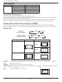
User Manual
BDL3215E
BDL4225E
TABLE OF CONTENTS
SAFETY INSTRUCTIONS..................................................................................................................................................................................................................... 1
Contents ..................................................................................................................................................................................................................................................... 7
Elements Name and Functions ............................................................................................................................................................................................................. 8
Control Panel ................................................................................................................................................................................................................................... 8
Terminal Panel .................................................................................................................................................................................................................................. 9
Remote Control............................................................................................................................................................................................................................. 10
Operating Range for the Remote Control ............................................................................................................................................................................. 11
Handling the remote control ..................................................................................................................................................................................................... 11
How to mount or attach table stand to the LCD Monitor ........................................................................................................................................................ 12
Setup Procedure ..................................................................................................................................................................................................................................... 14
Install the LCD Monitor in Portrait Mode ...................................................................................................................................................................................... 16
Connectivity ............................................................................................................................................................................................................................................ 17
Connectivity Diagram .................................................................................................................................................................................................................. 17
Connecting to a Personal Computer ....................................................................................................................................................................................... 18
Connecting to a Digital Interface Equipment ........................................................................................................................................................................ 19
Connecting to a DVD Player ...................................................................................................................................................................................................... 20
Connecting to a Stereo Amplifier ............................................................................................................................................................................................. 21
Basic Operation ...................................................................................................................................................................................................................................... 22
Power ON and OFF Modes ........................................................................................................................................................................................................ 22
Power Indicator.............................................................................................................................................................................................................................. 23
Using Power Management ........................................................................................................................................................................................................... 23
Display Signal of Video Source Setting to [VIDEO] ............................................................................................................................................................. 23
Picture Size ...................................................................................................................................................................................................................................... 23
Smart Picture Mode ...................................................................................................................................................................................................................... 24
Audio Source Switching ............................................................................................................................................................................................................... 24
Control Lock Mode ...................................................................................................................................................................................................................... 24
OSD Information .......................................................................................................................................................................................................................... 24
OSD (On-Screen-Display) Controls ................................................................................................................................................................................................ 25
PICTURE.......................................................................................................................................................................................................................................... 26
SCREEN ........................................................................................................................................................................................................................................... 28
AUDIO ............................................................................................................................................................................................................................................. 30
PIP (PICTURE IN PICTURE)...................................................................................................................................................................................................... 31
CONFIGURATION 1 .................................................................................................................................................................................................................. 32
CONFIGURATION 2 .................................................................................................................................................................................................................. 34
ADVANCED OPTION ................................................................................................................................................................................................................ 36
NOTE................................................................................................................................................................................................................................................ 39
Pixel defect policy ........................................................................................................................................................................................................................ 41
Features that do not require user interface ................................................................................................................................................................................... 42
Troubleshooting ..................................................................................................................................................................................................................................... 43
Specifications ........................................................................................................................................................................................................................................... 45
Pin Assignment ........................................................................................................................................................................................................................................ 49
User Manual BDL3215E / BDL4225E
SAFETY INSTRUCTIONS
WARNINGS AND PRECAUTIONS
KNOW THESE SAFETY SYMBOLS
CAUTION: TO REDUCE THE RISK OF ELECTRIC SHOCK, DO NOT REMOVE COVER (OR BACK). NO USER SERVICEABLE
PARTS INSIDE. REFER SERVICING TO QUALIFIED SERVICE PERSONNEL.
This symbol indicates high voltage is present inside. It is dangerous to make any kind of contact with any inside part of this
product.
This symbol alerts you that important literature concerning operation and maintenance has been included with this
product.
Note to CATV system installer: This reminder is provided to call CATV system installer’s attention to Article 820-40 of the National
(OHFWULFDO&RGH6HFWLRQRI&DQDGLDQ(OHFWULFDO&RGH3DUW,WKDWSURYLGHVJXLGHOLQHVIRUSURSHUJURXQGLQJDQGLQSDUWLFXODUVSHFLÀHV
that the cable ground shall be connected to the grounding system of the building as close to the point of cable entry as practical.
CAUTION:
to operate it.
)&&&6$UHJXODWLRQVVWDWHWKDWDQ\XQDXWKRUL]HGFKDQJHVRUPRGLÀFDWLRQVWRWKLVHTXLSPHQWPD\YRLGWKHXVHU·VDXWKRULW\
CAUTION:
To prevent electric shock, match the wide blade of plug to the wide slot, and fully insert the plug.
Attention:
3RXUpYLWHUOHVFKRFVpOHFWULTXHVLQWURGXLUHODODPHODSOXVODUJHGHODÀFKHGDQVODERPHFRUUHVSRQGDQWHGHODSULVHHW
SRXVVHUMXVTX·DXIRQG
Important:
One Federal Court has held that unauthorized recording of copyrighted TV programs is an infringement of U.S. copyright
laws. Certain Canadian programs may also be copyrighted and any unauthorized recording in whole or in part may be in violation of these
rights.
TO PREVENT DAMAGE WHICH MAY RESULT IN FIRE OR ELECTRIC SHOCK HAZARD, DO NOT EXPOSE THIS
APPLIANCE TO RAIN OR MOISTURE.
Read and follow these instructions when connecting and using your computer monitor:
v
v
v
v
v
v
v
v
v
v
v
v
Unplug the monitor if you are not going to use it for an extensive period of time.
Unplug the monitor if you need to clean it with a slightly damp cloth. The screen many be wiped with a dry cloth
when the power is off. However, never use alcohol, solvents or ammonia-based liquids.
Consult a service technician if the monitor does not operate normally when you have followed the instructions in this
manual.
The casing cover should be opened only by qualified service personnel.
Keep the monitor out of direct sunlight and away from stoves or any other heat source.
Remove any object that could fall into the vents or prevent proper cooling of the monitor’s electronics.
Do not block the ventilation holes on the cabinet.
Keep the monitor dry. To avoid electric shock, do not expose it to rain or excessive moisture.
If turning off the monitor by detaching power cable or DC power cord, wait for 6 seconds before attach the power
cable or DC power cord for normal operation.
To avoid the risk of shock or permanent damage to the set do not expose the monitor to rain or excessive moisture.
When positioning the monitor, make sure the power plug and outlet are easily accessible.
IMPORTANT: Always activate a screen saver program during your application. If a still image in high contrast remains
on the screen for an extended period of time, it may leave an ‘after-image’ or ‘ghost image’ on the front of the screen.
This is a well-known phenomenon that is caused by the shortcomings inherent in the LCD technology. In most cases
the afterimage will disappear gradually over a period of time after the power has been switched off. Be aware that the
after-image symptom cannot be repaired and is not covered under warranty.
1
User Manual BDL3215E / BDL4225E
REGULATORY INFORMATION
CE DECLARATION OF CONFORMITY
MMD declare under our responsibility that the product is in conformity with the following standards.
(16DIHW\UHTXLUHPHQWRI,QIRUPDWLRQ7HFKQRORJ\(TXLSPHQW
(15DGLR'LVWXUEDQFHUHTXLUHPHQWRI,QIRUPDWLRQ7HFKQRORJ\(TXLSPHQW
(1$$,PPXQLW\UHTXLUHPHQWRI,QIRUPDWLRQ7HFKQRORJ\(TXLSPHQW
EN61000-3-2:2006 (Limits for Harmonic Current Emission)
EN61000-3-3:1995+A1:2001+A2:2005 (Limitation of Voltage Fluctuation and Flicker)
following provisions of directives applicable.
2006/95/EC (Low Voltage Directive)
2004/108/EC (EMC Directive)
93/68/EEC (Amendment of EMC and Low Voltage Directive) and is produced by a manufacturing organization on ISO9000 level.
FEDERAL COMMUNICATIONS COMMISSION (FCC) NOTICE (U.S. Only)
7KLVHTXLSPHQWKDVEHHQWHVWHGDQGIRXQGWRFRPSO\ZLWKWKHOLPLWVIRUD&ODVV%GLJLWDOGHYLFHSXUVXDQWWR
Part 15 of the FCC Rules. These limits are designed to provide reasonable protection against harmful interference in a
UHVLGHQWLDOLQVWDOODWLRQ7KLVHTXLSPHQWJHQHUDWHVXVHVDQGFDQUDGLDWHUDGLRIUHTXHQF\HQHUJ\DQGLIQRWLQVWDOOHGDQG
used in accordance with the instructions, may cause harmful interference to radio communications. However, there is no
JXDUDQWHHWKDWLQWHUIHUHQFHZLOOQRWRFFXULQDSDUWLFXODULQVWDOODWLRQ,IWKLVHTXLSPHQWGRHVFDXVHKDUPIXOLQWHUIHUHQFHWR
UDGLRRUWHOHYLVLRQUHFHSWLRQZKLFKFDQEHGHWHUPLQHGE\WXUQLQJWKHHTXLSPHQWRIIDQGRQWKHXVHULVHQFRXUDJHGWRWU\
to correct the interference by one or more of the following measures:
5HRULHQWRUUHORFDWHWKHUHFHLYLQJDQWHQQD
,QFUHDVHWKHVHSDUDWLRQEHWZHHQWKHHTXLSPHQWDQGUHFHLYHU
&RQQHFWWKHHTXLSPHQWLQWRDQRXWOHWRQDFLUFXLWGLIIHUHQWIURPWKDWWRZKLFKWKHUHFHLYHULVFRQQHFWHG
&RQVXOWWKHGHDOHURUDQH[SHULHQFHGUDGLR79WHFKQLFLDQIRUKHOS
&KDQJHVRUPRGLÀFDWLRQVQRWH[SUHVVO\DSSURYHGE\WKHSDUW\UHVSRQVLEOHIRUFRPSOLDQFHFRXOGYRLGWKH
XVHU·VDXWKRULW\WRRSHUDWHWKHHTXLSPHQW
Use only RF shielded cable that was supplied with the monitor when connecting this monitor to a computer device.
To prevent damage which may result in fire or shock hazard, do not expose this appliance to rain or excessive moisture.
THIS CLASS B DIGITAL APPARATUS MEETS ALL REQUIREMENTS OF THE CANADIAN INTERFERENCE- CAUSING EQUIPMENT
REGULATIONS.
This device complies with Part 15 of the FCC Rules. Operation is subject to the following two conditions: (1) this device
may not cause harmful interference, and (2) this device must accept any interference received, including interference that
may cause undesired operation.
2
User Manual BDL3215E / BDL4225E
POLISH CENTER FOR TESTING AND CERTIFICATION NOTICE
The equipment should draw power from a socket with an attached protection circuit (a three-prong socket). All equipment that works
together (computer, monitor, printer, and so on) should have the same power supply source.
The phasing conductor of the room’s electrical installation should have a reserve short-circuit protection device in
the form of a fuse with a nominal value no larger than 16 amperes (A).
To completely switch off the equipment, the power supply cable must be removed from the power supply socket,
which should be located near the equipment and easily accessible.
A protection mark “B” confirms that the equipment is in compliance with the protection usage requirements of standards PN-93/T-42107
and PN-89/E-06251.
ELECTRIC, MAGNETIC AND ELECTRONMAGNETIC FIELDS (“EMF”)
1. MMD manufactures and sells many products targeted at consumers, which, like any electronic apparatus, in general have the ability to emit
and receive electromagnetic signals.
2. One of MMD’s leading Business Principles is to take all necessary health and safety measures for our products, to comply with all
applicable legal requirements and to stay well within the EMF standards applicable at the time of producing the products.
3. MMD is committed to develop, produce and market products that cause no adverse health effects.
4. MMD confirms that if its products are handled properly for their intended use, they are safe to use according to scientific evidence
available today.
5. MMD plays an active role in the development of international EMF and safety standards, enabling MMD to anticipate further developments
in standardisation for early integration in its products.
3
User Manual BDL3215E / BDL4225E
INFORMATION FOR UK ONLY
WARNING - THIS APPLIANCE MUST BE EARTHED.
Important:
(B)
(A)
This apparatus is supplied with an approved moulded 13A plug. To change a
fuse in this type of plug proceed as follows:
1. Remove fuse cover and fuse.
2. Fit new fuse which should be a BS 1362 5A,A.S.T.A. or BSI approved type.
3. Refit the fuse cover.
If the fitted plug is not suitable for your socket outlets, it should be cut off
and an appropriate 3-pin plug fitted in its place.
If the mains plug contains a fuse, this should have a value of 5A. If a plug
without a fuse is used, the fuse at the distribution board should not be
greater than 5A.
NOTE: The severed plug must be destroyed to avoid a possible shock hazard should it
be inserted into a 13A socket elsewhere.
How to connect a plug
The wires in the mains lead are coloured in accordance with the following
code:
BLUE - “NEUTRAL” (“N”)
BROWN - “LIVE” (“L”)
GREEN & YELLOW - “EARTH” (“E”)
1. The GREEN AND YELLOW wire must be connected to the terminal in the plug which
is marked with the letter “E” or by the Earth symbol or coloured GREEN or GREEN
AND YELLOW.
2. The BLUE wire must be connected to the terminal which is marked with the letter “N”
or coloured BLACK.
3. The BROWN wire must be connected to the terminal which marked with the letter
“L” or coloured RED.
Before replacing the plug cover, make certain that the cord grip is clamped over the
sheath of the lead - not simply over the three wires.
4
User Manual BDL3215E / BDL4225E
Ё⬉ᄤֵᙃѻક∵ᶧࠊᷛ䆚㽕∖Ё5R+6⊩㾘ᷛ⼎㽕∖ѻકЁ᳝↦᳝ᆇ⠽䋼ܗ
㋴ⱘৡ⿄ঞ䞣
᳝↦᳝ᆇ⠽䋼ܗ㋴
䬝
݁Ӌ䫀
⒈㘨㣃
( Cd )
(Cr 6+ )
( PBB )
{
{
{
䪙
( Pb )
{
∲
( Hg )
{
⎆䴶ᵓ
°
°
{
ƻ
ƻ
{
⬉䏃ᵓ㒘ӊ
°
{
{
{
{
{
䰘ӊ
䘹఼ˈ⬉⑤㒓ˈ䖲㒓
°
{
{
{
{
{
䘹఼⬉∴
°
{
{
{
{
{
䚼ӊৡ⿄
⒈Ѡ㣃䝮
( PBDE )
{
{㸼⼎䆹᳝↦᳝ᆇ⠽䋼䆹䚼ӊ᠔᳝ഛ䋼ᴤ᭭Ёⱘ䞣ഛSJ/T11363-2006ᷛޚ㾘ᅮⱘ䰤
䞣㽕∖ҹϟ
°㸼⼎䆹᳝↦᳝ᆇ⠽䋼㟇ᇥ䆹䚼ӊⱘᶤϔഛ䋼ᴤ᭭Ёⱘ䞣䍙ߎSJ/T11363-2006ᷛޚ㾘ᅮ
ⱘ䰤䞣㽕∖
10
ኛᄢཊᡰᐑ
࿒ᵧ↳ጦᡰᐑ)๒ྐྵ*᭓ኔᒨዊ၌࿌ቇ࿌࿌ᒃሸḜᆾທᕞྜྷ༻ᙚᄢཊቇᛐ๖ຂᨤᣝཉ༜ምᆾᎷ⋸
᭓ኔᒨዊཊເᄢཊ᭓ኔᒨዊຂᨤᮯᮒឭ࿁⇺ᐏጿᆾᮯᄷ้ᄀಪᖺឭ࿁⇺ᐏᨔᒃቇᡰᐑಫ
5
User Manual BDL3215E / BDL4225E
NORTH EUROPE (NORDIC COUNTRIES) INFORMATION
Placering/Ventilation
VARNING:
FÖRSÄKRA DIG OM ATT HUVUDBRYTARE OCH UTTAG ÄR LÄTÅTKOMLIGA, NÄR DU STÄLLER DIN UTRUSTNING PÅPLATS.
Placering/Ventilation
ADVARSEL:
SØRG VED PLACERINGEN FOR, AT NETLEDNINGENS STIK OG STIKKONTAKT ER NEMT TILGÆNGELIGE.
Paikka/Ilmankierto
VAROITUS:
SIJOITA LAITE SITEN, ETTÄ VERKKOJOHTO VOIDAAN TARVITTAESSA HELPOSTI IRROTTAA PISTORASIASTA.
Plassering/Ventilasjon
ADVARSEL:
NÅR DETTE UTSTYRET PLASSERES, MÅ DU PASSE PÅ AT KONTAKTENE FOR STØMTILFØRSEL ER LETTE Å NÅ.
END-OF-LIFE DISPOSAL
Your new TV/Monitor contains materials that can be recycled and reused. Specialized companies can recycle your
product to increase the amount of reusable materials and to minimize the amount to be disposed of.
Please find out about the local regulations on how to dispose of your old monitor from your local Philips dealer.
(For customers in Canada and U.S.A.)
This product may contain lead and/or mercury. Dispose of in accordance to local-state and federal regulations.
For additional information on recycling contact www.eia.org (Consumer Education Initiative)
WASTE ELECTRICAL AND ELECTRONIE EQUIPMENT-WEEE
Attention users in European Union private households
This marking on the product or on its packaging illustrates that, under European Directive 2002/96/EG governing used
electrical and electronic appliances, this product may not be disposed of with normal household waste. You are responsible
IRUGLVSRVDORIWKLVHTXLSPHQWWKURXJKDGHVLJQDWHGZDVWHHOHFWULFDODQGHOHFWURQLFHTXLSPHQWFROOHFWLRQ7RGHWHUPLQHWKH
ORFDWLRQVIRUGURSSLQJRIIVXFKZDVWHHOHFWULFDODQGHOHFWURQLFFRQWDFW\RXUORFDOJRYHUQPHQWRIÀFHWKHZDVWHGLVSRVDO
organization that serves your household or the store at which you purchased the product.
Attention users in United States:
Like all LCD products, this set contains a lamp with Mercury. Please dispose of according to all Local, State and Federal Laws. For the
disposal or recycling information, contact: www.mygreenelectronics.com or www.eiae.org.
6
User Manual BDL3215E / BDL4225E
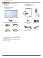
* The following components are prepared as options.
Contents
v
v
v
v
v
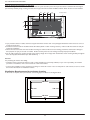
BDL3215E/BDL4225E monitor pack* should include:
v
LCD monitor
v
Power cord (1.8 m)
v
VGA Signal Cable (1.8 m)
v
User Manual
v
Remote Control and AAA Batteries
v
Quick installation guide.
Table stand
Main switch cover
Screw for Main Switch cover x 2
BNC TO RCA adapter x 5
Logo guider
POWER
SMART
VIDEO
SOURCE
ON/OFF
INPUT
AUDIO
SOURCE
PIP
CONTRAST
CHANGE
BRIGHTNESS
DISPLAY
MENU
SET
AUTO
ADJUST
EXIT
VOL UP
MUTE
VOL DOWN
User’s Manual
Remote Control
and AAA Batteries
Main switch cover
* The supplied power cord varies depending on destination.
For EU
Screw for Main switch cover
(3 x 6) x 2
BNC-RCA adapter x 5
For China
Video Signal Cable
(D-SUB to D-SUB Cable)
For North America
For UK
Power cord
* Please make sure that for all other regions, apply a power
cord that conforms to the AC voltage of the power socket and
has been approved by and complies with the safety regulations
of the particular country
<RXPLJKWOLNHWRVDYHWKHSDFNDJHER[DQGSDFNLQJPDWHULDO
for shipping the monitor.
7
Logo guider
User Manual BDL3215E / BDL4225E
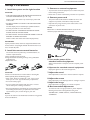
Elements Name and Functions
Control Panel
f
e
c
d
b
a
g
h
a POWER button (B): To switch the power on/off.
b CH (+) button: To move the highlight bar up to adjust the selected item while OSD menu is on.
c CH (-) button: To move the highlight bar down to adjust the selected item while OSD menu is on.
d MENU button: To return to previous menu while OSD menu is on or to activate the OSD menu when the OSD menu is
off.
e VOL (+) button: To increase the adjustment while OSD menu is on, or to increase the audio output level while the OSD
menu is off.
f VOL (-) button: To decrease the adjustment while OSD menu is on, or to decrease the audio output level while the OSD
menu is off.
g Remote control sensor and Power indicator: To receive the IR signal from the remote control. The indicator would
show blue when the LCD monitor is active, and would turn blank when the LCD is POWER OFF. While in the case of the
system is in power save mode, it would show amber. When SCHEDULE is enabled, it would show blinking blue.
h Main Power Switch: To turn the main power on/off.
NOTE:
Keyboard Control Lock Mode: This function completely disables the access to all Keyboard Control functions. To enable the keyboard
control lock, press both “CH+” and “CH-” buttons and hold down continuously for more than 3 seconds. To recover back to the user
mode, press both “CH+” and “CH-” buttons and hold continuously for three 3 seconds.
8
User Manual BDL3215E / BDL4225E
Terminal Panel
11
(OUT)
(OUT)
(IN)
(IN)
1
2
3
4
5
b AUDIO OUT
* This connector does not support analog input.
To input audio signal from an external equipment such as
computers, VCRs, or DVD players.
j VGA (BNC) [R, G, B, H, V] or COMPONENT [Y, Cb/
Pb, Cr/Pr]
d VIDEO INPUT/OUTPUT Connector
v
10
To input digital RGB signals from a computer or other HDTV
device with digital RGB output.
c AUDIO IN 1, 2, 3
VIDEO OUT connector (BNC): To output
composite video signal from VIDEO IN connector.
9
i DVI-D INPUT
To output the audio signal from AUDIO IN 1, 2, or 3 jack to
an external device (Stereo receiver, amplifier, etc.).
v
8
To input analog RGB signals from a computer or from other
RGB equipment.
Connect the supplied power cord to the wall outlet.
VIDEO IN connector (BNC): To input composite
video signal.
7
h VGA IN (mini D-sub 15 pin)
a AC IN connector
v
6
To input analog RGB or Y, Cb/Pb,Cr/Pr signals from DVD
players, HDTV decoders, set-top-box or game consoles etc.
k Kensington Lock
For security and theft prevention.
S-VIDEO IN connector (Mini DIN 4 pin): To input
S-VIDEO (Y/C separate signal).
e EXTERNAL CONTROL (D-Sub 9 pin)
Connect RS-232C input from external equipment such as
computers for the use of loop through function.
f VGA OUT (mini D-Sub 15 pin)
To output the signal from VGA IN and RGB component.
g HDMI IN
Connecting equipment such as DVD players, HDTV devices,
or Set-Top-Box.
9
User Manual BDL3215E / BDL4225E
d CONTRAST button
Remote Control
To start CONTRACT OSD selection, and then press “+”
or “-” button to adjust the value.
e DISPLAY button
POWER
1
To turn on/off the setting information displayed on the rightup corner of the screen.
10
SMART
VIDEO
SOURCE
f “-” button
AUDIO
SOURCE
2
v
v
11
12
g SET button
PIP
To activate the setting with OSD menu.
3
ON/OFF
INPUT
h AUTO ADJUST button
CHANGE
4
13
CONTRAST
BRIGHTNESS
5
To execute the AUTO ADJUST function.
i MUTE button
14
15
Mutes or restores audio output.
MENU
DISPLAY
6
To decrease the adjustment with OSD menu.
To move the sub-picture left when in “PIP” mode.
j VIDEO SOURCE button
16
SET
7
8
To set video source by toggle selection from [HDMI],
[DVI-D], [VGA], [COMPONENT], [S-VIDEO)], [VIDEO]
and [VGA(BNC)].
17
EXIT
AUTO
ADJUST
k AUDIO SOURCE button
18
To set audio source by toggle selection from [AUDIO 1] to
[AUDIO2], [AUDIO3] and [HDMI].
VOL UP
19
MUTE
NOTE: [HDMI] is only selectable when video source is set
to [HDMI].
20
9
VOL DOWN
l SIZE button
To set picture size by toggle selection from [FULL],
[NORMAL], [CUSTOM] , [DYNAMIC] and [REAL].
NOTE: [DYNAMIC] is for video mode only.
m BRIGHTNESS button
To start the BRIGHTNESS OSD selection, and then press
“+” or “-” button to adjust the value.
n o button
v
v
To move the highlight bar up to adjust the selected item
when OSD menu is on.
To move the sub-picture up when in “PIP” mode.
o MENU button
a POWER button
v
v
To turn the OSD menu on/off.
To turn the power on/off.
If LED Power Indicator on the monitor is not lightening,
then the remote control will not work.
p “+” button
v
v
b SMART button
v
v
v
v
v
To increase the adjustment with OSD menu.
To move the sub-picture right when in “PIP” mode.
q EXIT button
To select smart picture mode from [HIGHBRIGHT],
[STANDARD], [sRGB], [CINEMA].
HIGHBRIGHT: for moving image such as Video
STANDARD: for images (Factory setting)
sRGB: for text based images
CINEMA: for movies.
To return to a previous channel or menu screen.
r œ button
v
v
To move the highlight bar down to adjust the selected
item when OSD menu is on.
To move the sub-picture down when in “PIP” mode.
s VOL UP button
c PIP (Picture In Picture) button
To increase the audio output level.
v
v
ON/OFF button: To turn PIP mode ON/OFF.
INPUT button: To select the input signal for the subpicture.
v CHANGE button: To exchange between the main
picture and sub-picture.
NOTE: The “PIP” and “POP” modes do not work if the
screen size is “CUSTOM” or “REAL”.
t VOL DOWN button
To decrease the audio output level.
10
User Manual BDL3215E / BDL4225E
Operating Range for the Remote
Control
Handling the remote control
Do not subject to strong shock.
Use the remote control by pointing it towards the remote
control sensor on the LCD monitor.
Use the remote control unit within a distance of about 7 m/23 ft
from the front of the remote control sensor on the LCD monitor
and within horizontal and vertical angle 30° with a distance of
about 3 m/10 ft.
30
'RQRWDOORZZDWHURURWKHUOLTXLGWRVSODVKWKHUHPRWH
control. If the remote control gets wet, wipe it dry
immediately.
$YRLGH[SRVXUHWRKHDWDQGVWHDP
Other than to install the batteries, do not open the remote
control.
30
POWER
SMART
VIDEO
SOURCE
AUDIO
SOURCE
PIP
ON/OFF
INPUT
CONTRAST
CHANGE
BRIGHTNESS
DISPLAY
MENU
SET
AUTO
ADJUST
EXIT
VOL UP
MUTE
VOL DOWN
NOTE:
The remote control system may not function when direct sunlight
or strong illumination strikes the remote control sensor of the
LCD monitor, or when there is an obstacle in the radiation path.
11
User Manual BDL3215E / BDL4225E
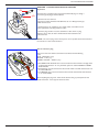
How to mount or attach table stand to the LCD
Monitor
Installs the LCD monitor in one of the following two ways:
Way I: Attach and remove the table stand
How to install table stand
1. Please turn the monitor off.
2. After inserting table stand in guide block, fasten the thumbscrews on both sides of the monitor.
NOTE:
Install the table stand with their longer portions directing to the front.
Thumbscrews
Longer portions directs to the front
Table stand
In the upright position
How to remove the table stand
1. Spread the protective sheet on the flat surface.
2. Make the monitor lying on the protective sheet.
3. Remove the screws using a screwdriver and place them in a safe place for reuse.
12
User Manual BDL3215E / BDL4225E
Way II: Mount the monitor on the wall
Before mounting the monitor to the wall, make sure that the system has been power-off and you have obtain a standard wall-mounting kit
(commercially available). Using mounting interface that comply with TÜV-GS and/or UL1678 standard in North America is recommended.
100
100
100
100
Protective Sheet
100
100
Table
Tabletop stand
1. Lay a protective sheet on a table, which was wrapped around the monitor when it was packaged, beneath the screen surface so as not to
scratch the screen face.
2. This device cannot be used or installed without the Tabletop Stand or other mounting accessory. Make sure all these stuffs are ready for
wall-mount installation.
3. Follow the instructions that come with the base mounting kit. Failure to follow correct mounting procedures could result in damage to
the equipment or injury to the user or installer. Product warranty does not cover damage caused by improper installation.
4. For the wall-mounting kit, use M6 mounting screws (having a length 10 mm longer than the thickness of the mounting bracket) and tighten
WKHPVHFXUHO\5HFRPPHQGHGWRUTXH1vFP
Caution:
For preventing the monitor from falling.
Install the monitor with metal brackets for wall or ceiling installation (commercially available) on your own responsibility. For detailed
procedures of installation, refer to the instructions of the metal brackets.
7ROHVVHQWKHSUREDELOLW\RILQMXU\DQGGDPDJHUHVXOWLQJIURPIDOORIWKHPRQLWRULQFDVHRIHDUWKTXDNHRURWKHUGLVDVWHUEHVXUHWRFRQVXOW
the bracket manufacturer for installation location.
Ventilation Requirements for enclosure locating
To allow heat to disperse, leave space between surrounding objects as shown in the diagram below.
100 mm
100 mm
100 mm
100 mm
13
User Manual BDL3215E / BDL4225E
Setup Procedure
1. Install the system on the right location
3. Connect to external equipment
CAUTION:
7RSURWHFWWKHFRQQHFWHGHTXLSPHQWWXUQRIIWKHPDLQSRZHU
before making connections.
Please refer to section “Connectivity” P.17~P.21 for operations.
THE LCD MONITOR MUST BE MOVED OR INSTALLED BY
TWO OR MORE PERSONS. (For 42” only)
4. Connect power cord
Failure to follow this caution may result in injury if the LCD
monitor falls.
The power outlet socket should be installed as near to the
HTXLSPHQWDVSRVVLEOHDQGVKRXOGEHHDVLO\DFFHVVLEOH
DO NOT ATTEMPT TO INSTALL THE LCD MONITOR BY
YOURSELF.
Fully insert the prongs into the power outlet socket. Loose
connection may cause noise.
7KH/&'GLVSOD\PXVWEHLQVWDOOHGE\DTXDOLÀHGWHFKQLFLDQ
Contact your dealer for more information.
NOTE:
Please refer to “SAFETY INSTRUCTIONS” section of this
manual for proper selection of AC power cord.
DO NOT MOUNT OR OPERATE THE DISPLAY UPSIDE
DOWN, FACE UP, OR FACE DOWN.
DO NOT INSTALL THE LCD MONITOR WHERE IT WILL BE
EXPOSED TO DIRECT SUNLIGHT.
Failure to follow this caution will result in display defects.
IMPORTANT:
Lay the protective sheet, which was wrapped around the LCD
monitor when it was packaged, beneath the LCD monitor so as
not to scratch the panel.
2. Install the remote control batteries
The remote control is powered by 1.5V AAA batteries. To
install or replace batteries:
1. Press and slide to open the cover.
2. Align the batteries according to the (+) and (–) indications
inside the case.
3. Replace the cover.
5. Turn on the power of the
attached external equipment
When connected with a computer, turn the computer power
RQÀUVW
6. Operate the attached external equipment
'LVSOD\WKHVLJQDOIURPWKHH[WHUQDOHTXLSPHQW
7. Adjust the sound
CAUTION:
Incorrect use of batteries can result in leaks or bursting. Be
careful especially about the following points.
0DNHDGMXVWPHQWVWRGHFUHDVHRULQFUHDVHYROXPHLIUHTXLUHG
Place “AAA” batteries matching the + and - signs on each
battery to the + and - signs of the battery compartment.
8. Adjust the screen
'RQRWPL[EDWWHU\W\SHV
9. Adjust the image
0DNHDGMXVWPHQWVWRWKHGLVSOD\SRVLWLRQRUVHWWLQJVLIUHTXLUHG
Do not combine new batteries with used ones. It causes
shorter battery life or leakage of batteries.
0DNHDGMXVWPHQWVRIEULJKWQHVVRUFRQWUDVWLIUHTXLUHG
10. Recommended Adjustment
5HPRYHGHDGEDWWHULHVLPPHGLDWHO\WRSUHYHQWEDWWHU\OLTXLG
from leaking into the battery compartment. Don’t touch
H[SRVHGEDWWHU\DFLGLWFDXVHGDPDJHWR\RXUVNLQ
To reduce the risk of “image persistence”, please adjust the
following items based on the application being used:
NOTE:
“POWER SAVE”, “PANEL SAVING”, “DATE AND TIME”,
“SCHEDULE”.
If you do not intend to use the Remote Control for a long period,
remove the batteries.
14
User Manual BDL3215E / BDL4225E
11. To prevent the main power
switch from being changed
To prevent the possibility of main power switch being carelessly
pushed, please attach the main switch cover (accessory) onto
it.
NOTE:
Remove main power switch cover to turn off the display.
Screw
Main switch cover
15
User Manual BDL3215E / BDL4225E
Install the LCD Monitor in Portrait Mode
BDL3215E/BDL4225E can be installed in portrait position, under the following conditions:
Caution:
Portrait mode is effective only when wall-mounted or ceiling-mounted. The table stand can not be used for the monitor in portrait position.
Placing the monitor in portrait position, will shorten the average life of the LCD backlight.
Operational Environment (Temperature) shall be limited, as shown below:
Operational
Environment
Temperature
5 - 35 °C / 41 - 95 °F
Humidity
20 - 80 % (Without condensation)
Please orientate the monitor in the direction shown as the right figure:
Do not place monitor in landscape in any other manner.
How to set-up
1. Remove the table stand if they are attached.
2. The “
” logo should be on the LEFT side when facing the monitor.
Clockwise
Counterclockwise
90
90
How to Remove the Logo for landscape mode?
1. Prepare a piece of paper with a cutting area of logo as a protector to prevent the front bezel from scratching.
2. Using a knife, carefully remove the logo sticker with the paper placing beneath.
3. Tear off the logo sticker.
1
2
3
How to Use the Logo Guider for Portrait Mode?
(a) Before applying, make sure the guider is well shaped. The “PHILIPS” sticker attached on the end of it could be folded back as figure (a).
(b) Turn back the logo end of the guider and remove the sticky tape of the logo.
(c) Slide the logo guider along the short side of the front bezel as figure c & then return the logo end of the guider back to the right side.
(d) With your left hand fixing the guider, scrunch the logo by your right hand to make it stuck firmly on the front bezel.
(e) Remove the guider and leave the logo over the front bezel.
16
User Manual BDL3215E / BDL4225E
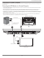
Connectivity
Before making connections:
)LUVWWXUQRIIWKHSRZHURIDOOWKHDWWDFKHGHTXLSPHQWVEHIRUHPDNLQJFRQQHFWLRQV
5HIHUWRWKHXVHUPDQXDOLQFOXGHGLQHDFKVHSDUDWHSLHFHRIHTXLSPHQW
Connectivity Diagram
BDL3215E / BDL4225E
VCR
Equipment with
Digital interface
DVD player
BDL3215E / BDL4225E
Personal computer
(Second monitor)
17
HD or laser disk player
User Manual BDL3215E / BDL4225E
Connecting to a Personal Computer
As you finish the connection between the computer and the LCD monitor, you could play the contents in the computer and display them on
the LCD monitor.
Connecting the LCD Monitor to a Personal Computer
To achieve this, apply the supplied VGA signal cable (mini D-sub 15 pin to mini D-sub 15 pin) to make connection between PC and LCD
monitor (VGA IN connector).
When connecting more than one LCD monitors to PC, apply another VGA signal cable (mini D-sub 15 pin to mini D-sub 15 pin; it’s
commercially available) to make connection between LCD monitor (VGA OUT connector) and the other (VGA IN connector).
The AUDIO IN 1, 2, 3 or HDMI can be connected for audio input using RCA cable. After choosing one of the AUDIO IN connectors, you
might need to select AUDIO 1, 2, 3 or HDMI using the AUDIO SOURCE button on the remote control. HDMI (for audio) is selectable
only when HDMI (for video) is selected.
When connecting more than one LCD monitors to PC, apply RCA cable to make connection between LCD monitor (AUDIO OUT
connector) and the other (AUDIO IN 1, 2, 3). HDMI source is not suitable for this case.
BDL3215E / BDL4225E
To audio output
To analog VGA output
Mini D-sub 15 pin
PC or IBM compatible
RCA
Mini D-sub 15 pin
BDL3215E / BDL4225E
Second monitor
18
User Manual BDL3215E / BDL4225E
Connecting to a Digital Interface Equipment
Connections can be made between LCD monitor and other digital equipment that is equipped with a digital interface compliant with DVI
(Digital Visual Interface) standard.
Connect the LCD Monitor to a Computer with a Digital Output
HDMI IN connector accepts HDMI cable.
HDMI IN connector can receive video from HDMI source (applying a HDMI to HDMI cable) or DVI-D source (applying a HDMI to DVI
cable) of PC.
7RHQVXUHWKHGLVSOD\TXDOLW\XVHTXDOLW\SUHVFULEHGFDEOHVZLWK'9,VWDQGDUGV
The AUDIO IN 1, 2, 3 or HDMI connector can be chosen to receive audio source. Select AUDIO 1, 2, 3 or HDMI from the AUDIO
SOURCE button on the remote control. HDMI (for audio) is only selectable only when HDMI (for video) is selected.
Note that the signal input from HDMI connector cannot be output to the VGA OUT connector.
Equipment with digital interface
such as personal computer with
VGA output (TMDS)
BDL3215E / BDL4225E
To audio output
To HDMI output
HDMI connector
19
User Manual BDL3215E / BDL4225E
Connecting to a DVD Player
As you finish the connection between the DVD player and the LCD monitor, you could display the contents from the played DVD on the
LCD monitor. You might like to refer to your DVD player’s manual for further information.
Connect the LCD Monitor to a DVD Player
To achieve this, apply component (YPbPr) cable to make connection between DVD player (Y, Cb/Pb, Cr/Pr Out) and LCD monitor
(COMPONENT/ YPbPr connector). If your DVD player supports HDMI signal, apply HDMI to HDMI cable for the connection.
The AUDIO IN 2, 3 (both of RCA connector type) can be used for audio input. Select [AUDIO 1] (for 3.5ɔ phone jack), [AUDIO 2],
[AUDIO 3] or [HDMI] from the AUDIO SOURCE button on the remote control. HDMI (for audio) is selectable only when HDMI (for
video) is selected.
To audio left output
BDL3215E / BDL4225E
COMPONENT
(YPbPr)
To audio right output
To DVD Component video output
DVD player
HDMI connector
COMPONENT
(YPbPr)
HDMI connector
RCA
20
To HDMI output
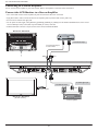
User Manual BDL3215E / BDL4225E
&RQQHFWLQJWRD6WHUHR$PSOLÀHU
You can connect stereo amplifier to your LCD monitor. Refer to the amplifier’s manual for further information.
&RQQHFWWKH/&'0RQLWRUWRD6WHUHR$PSOLÀHU
7XUQRQWKH/&'PRQLWRUDQGWKHDPSOLÀHURQO\DIWHUDOOFRQQHFWLRQVKDYHEHHQFRQQHFWHG
$SSO\5&$FDEOHWRPDNHFRQQHFWLRQVEHWZHHQWKHDPSOLÀHUDXGLRLQDQGWKH/&'PRQLWRUDXGLRRXW
Do not reverse audio left and right jacks.
For the preferred audio signal, select [AUIDO1], [AUDIO2], [AUDIO3] or [HDMI] from the AUDIO SOURCE button on the remote
control. HDMI (for audio) is selectable only when HDMI (for video) is selected.
AUDIO OUT RCA connectors output sound from the selected AUDIO SOURCE.
BDL3215E / BDL4225E
To audio left input
To composite Output
In case of VCR
RCA
BNC
To audio right input
To audio left input
BNC-RCA adaptor
RCA
BDL3215E / BDL4225E
(Second monitor)
External speaker
21
User Manual BDL3215E / BDL4225E
Basic Operation
Power ON and OFF Modes
The LCD monitor power indicator will turn blue while powered on and will turn blank while powered off. The monitor can be powered on
or off using the following three options:
1. Pressing the Main Power Switch.
When the Main Power Switch is turned off, the LCD monitor,
the remote control, the power button and the indicator will not
work. Make sure to turn the Main Power Switch on before using
the other two options.
Main power switch
ON
OFF
2. Pressing the power button.
Before pressing the power button, be sure to turn on the Main
Power button on the LCD monitor.
3. Using the remote control.
Before operating the remote control, be sure to turn on the Main
Power Switch on the LCD monitor.
22
User Manual BDL3215E / BDL4225E
Power Indicator
LED Status
Power Status
LED behavior
LED active
Normal on
Blue
Standby
Amber
RC command
Blue blinking
RC / DC power off
Black
AC power switch off
Black
Using Power Management
The LCD monitor follows the VESA approved DPM Power Management function.
The power management function is an energy saving function that automatically reduces the power consumption of the display when the
keyboard or the mouse has not been used for a certain period of time.
If the power management feature on the LCD monitor has been set to “ON” mode, this allows the system to enter a Power Saving Mode
when no signal is applied. This could potentially increase the life time and decrease the power consumption of the LCD monitor.
Display Signal of Video Source Setting to [VIDEO]
Use the input button on the front panel or the VIDEO SOURCE button on the remote control to set video source to [VIDEO].
Use the COLOR SYSTEM OSD menu to select [AUTO], [NTSC], [PAL], [SECAM], [PAL60], [4.43NTSC], according to your video format.
Picture Size
FULL
HDMI, VGA
NORMAL
DVI-D, VGA (BNC)
REAL
FULL
S-VIDEO, VIDEO
NORMAL
COMPONENT(BNC)
Signal Type
CUSTOM
REAL
NORMAL SIZE
DYNAMIC
CUSTOM
Recommended Size
NORMAL
4:3
DYNAMIC
16:9
FULL
NORMAL:
Display with the input signal aspect ratio from PC signal, or display in 4:3 aspect ratio at COMPONENT or VIDEO signal.
FULL:
Display in the entire screen.
DYNAMIC:
([SDQGSLFWXUHVWRWKHHQWLUHVFUHHQZLWKQRQOLQHDULW\
CUSTOM (ZOOM): Images can be expanded beyond the active display area. The image which is outside of the active display area would
not be shown.
REAL:
ZOOM
,PDJHZLOOEHGLVSOD\HGIRURQHE\RQHSL[HO
ZOOM
23
User Manual BDL3215E / BDL4225E
Smart Picture Mode
HIGHBRIGHT
HDMI, VGA DVI-D
STANDARD
sRGB
VGA (BNC)
HIGHBRIGHT
COMPONENT, VIDEO,
S-VIDEO
STANDARD
CIMEMA
Audio Source Switching
You can select audio source by using the AUDIO SOURCE button on the remote control.
HDMI
HDMI
Other than HDMI
AUDIO1
AUDIO1
AUDIO2
AUDIO2
AUDIO3
AUDIO3
Control Lock Mode
This function disables the operation of all local keyboard buttons on TV. When Control lock mode is activated, all adjustments via local
keyboard buttons will not work.
To disable the buttons, press and hold down the CH+ and CH- buttons together for at least 3 seconds.
To enable the buttons, press and hold down the CH+ and CH- buttons together for at least 3 seconds again.
OSD Information
HDMI, VGA, VGA (BNC), DVI-D
VGA
Video Source
1024 x 768
Input signal Information
48kHz 60Hz
AUDIO : 1
SIZE : FULL
Audio Source
Picture Size
COMPONENT
COMPONENT
AUDIO : 3
SIZE : FULL
Video Source
Audio Source
Picture Size
S-VIDEO, VIDEO
S-VIDEO
NTSC
AUDIO :3
SIZE : NORMAL
Video Source
Color System of Input Signal
Audio Source
Picture Size
PIP or POP
Main: VGA / Sub: S-VIDEO
VGA
1024 x 768
Main picture Information
48kHz 60Hz
AUDIO : 1
S-VIDEO
Sub picture Information
NTSC
SIZE : FULL
Main picture Information
24
User Manual BDL3215E / BDL4225E
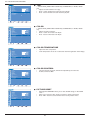
OSD (On-Screen-Display) Controls
Press MENU button to
open Main menu. Press
o or œ button to select
the sub-menu
Press o or œ, and “+” or
“-” button to make selection
or adjust the setting. Press
SET button to enable the
setting.
Press MENU or EXIT
button to exit.
Remote Control
MENU
SET
SET
SET
EXIT
Press MENU button to
open Main menu. Press
CH + or CH - button to
select.
Control Panel
CH + / CH - and
VOL + / VOL - button
CH + / CH button
PICTURE
Press MENU button to
exit.
MENU button
PICTURE
PICTURE
BRIGHTNESS
70
BRIGHTNESS
70
BRIGHTNESS
CONTRAST
50
CONTRAST
50
CONTRAST
SHARPNESS
50
SHARPNESS
50
SHARPNESS
BLACK LEVEL
50
NOISE REDUCTION
OSD screen
Press CH + or CH - as o
or œ button , and VOL + or
VOL - as Wor p button to
make selections or adjust the
settings.
Press VOL + as Wbutton to
enable the setting.
LOW
BLACK LEVEL
50
NOISE REDUCTION
LOW
TINT
TINT
TINT
COLOR
COLOR
COLOR
COLOR TEMPERATURE
NATIVE
COLOR TEMPERATURE
NATIVE
90
50
50
BLACK LEVEL
COLOR CONTROL
COLOR CONTROL
PICTURE RESET
PICTURE RESET
PICTURE RESET
Adjust
set: Enter
exit: BACK
menu: Quit
Sel
Adjust
25
set: Enter
exit: BACK
menu: Quit
LOW
COLOR TEMPERATURE
COLOR CONTROL
Sel
50
NOISE REDUCTION
Sel
Adjust
NATIVE
set: Enter
exit: BACK
menu: Quit
User Manual BDL3215E / BDL4225E
Main-Menu
PICTURE
Ê BRIGHTNESS
PICTURE
BRIGHTNESS
70
CONTRAST
50
SHARPNESS
50
BLACK LEVEL
50
NOISE REDUCTION
v
v
v
Adjusts overall images and background screen brightness.
Press + button to increase brightness.
Press - button to decrease brightness.
LOW
TINT
COLOR
COLOR TEMPERATURE
NATIVE
COLOR CONTROL
PICTURE RESET
Sel
Adjust
set: Enter
exit: BACK
menu: Quit
Ê CONTRAST
PICTURE
BRIGHTNESS
70
CONTRAST
50
SHARPNESS
50
BLACK LEVEL
50
NOISE REDUCTION
v
v
v
Adjusts image brightness of the input signal.
Press + button to increase contrast.
Press - button to decrease contrast.
LOW
TINT
COLOR
COLOR TEMPERATURE
NATIVE
COLOR CONTROL
PICTURE RESET
Sel
Adjust
set: Enter
exit: BACK
menu: Quit
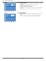
Ê SHARPNESS
PICTURE
BRIGHTNESS
70
CONTRAST
50
SHARPNESS
50
BLACK LEVEL
50
NOISE REDUCTION
LOW
TINT
COLOR
COLOR TEMPERATURE
NATIVE
v
v
v
v
v
This function is digitally capable to keep a crisp image at any timing.
It is adjustable to get a distinct or soft image.
Each picture mode can be set independently.
Press + button to increase sharpness.
Press - button to decrease sharpness.
COLOR CONTROL
PICTURE RESET
Sel
Adjust
set: Enter
exit: BACK
menu: Quit
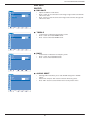
Ê BLACK LEVEL
PICTURE
BRIGHTNESS
70
CONTRAST
50
SHARPNESS
50
BLACK LEVEL
50
NOISE REDUCTION
v
v
v
Adjusts image brightness for the background.
Press + button to increase black level.
Press - button to decrease black level.
LOW
TINT
COLOR
COLOR TEMPERATURE
NOTE: sRGB picture mode is the standard one and cannot be changed.
NATIVE
COLOR CONTROL
PICTURE RESET
Sel
Adjust
set: Enter
exit: BACK
menu: Quit
Ê NOISE REDUCTION
PICTURE
BRIGHTNESS
70
CONTRAST
50
SHARPNESS
50
BLACK LEVEL
50
NOISE REDUCTION
LOW
TINT
COLOR
COLOR TEMPERATURE
* : INPUT S-VIDEO, VIDEO only
v Adjusts the noise reduction level.
v Press + button to increase noise reduction level.
v Press - button to decrease noise reduction level.
NATIVE
COLOR CONTROL
PICTURE RESET
Sel
Adjust
set: Enter
exit: BACK
menu: Quit
26
User Manual BDL3215E / BDL4225E
Ê TINT
PICTURE
BRIGHTNESS
70
CONTRAST
50
SHARPNESS
50
BLACK LEVEL
50
NOISE REDUCTION
LOW
TINT
COLOR
COLOR TEMPERATURE
NATIVE
* : INPUT HDMI (HDMI INPUT MODE-HD), COMPONENT, S-VIDEO, VIDEO
only.
v Adjusts the color balance in an image.
v Press + button the flesh tone color becomes greenish.
v Press - button the flesh tone color becomes purplish.
COLOR CONTROL
PICTURE RESET
Sel
Adjust
set: Enter
exit: BACK
menu: Quit
Ê COLOR
PICTURE
BRIGHTNESS
70
CONTRAST
50
SHARPNESS
50
BLACK LEVEL
50
NOISE REDUCTION
LOW
TINT
COLOR
COLOR TEMPERATURE
NATIVE
* : INPUT HDMI (HDMI INPUT MODE-HD), COMPONENT, S-VIDEO, VIDEO
only.
v Adjusts the color saturation.
v Press + button to increase color depth.
v Press - button to decrease color depth.
COLOR CONTROL
PICTURE RESET
Sel
Adjust
set: Enter
exit: BACK
menu: Quit
Ê COLOR TEMPERATURE
PICTURE
BRIGHTNESS
70
CONTRAST
50
SHARPNESS
v
v
Adjust the color temperature.
Color temperature can be set to values that match the application of the display.
50
BLACK LEVEL
50
NOISE REDUCTION
LOW
TINT
COLOR
COLOR TEMPERATURE
NATIVE
COLOR CONTROL
PICTURE RESET
Sel
Adjust
set: Enter
exit: BACK
menu: Quit
Ê COLOR CONTROL
PICTURE
BRIGHTNESS
70
CONTRAST
50
SHARPNESS
v
v
The color level of red, green, and blue are adjustable by the color bars.
R: Red, G: Green, B: Blue
50
BLACK LEVEL
50
NOISE REDUCTION
LOW
TINT
COLOR
COLOR TEMPERATURE
NATIVE
COLOR CONTROL
PICTURE RESET
Sel
Adjust
set: Enter
exit: BACK
menu: Quit
Ê PICTURE RESET
v
PICTURE
BRIGHTNESS
70
CONTRAST
50
SHARPNESS
50
BLACK LEVEL
50
NOISE REDUCTION
LOW
TINT
v
v
Selecting PICTUER RESET allows you to reset all OSD settings in “PICTURE”
menu.
Select “Yes” and press “SET” button to restore to factory preset data.
Press “EXIT” button to cancel and then return to the previous menu.
COLOR
COLOR TEMPERATURE
NATIVE
COLOR CONTROL
PICTURE RESET
Sel
Adjust
set: Enter
exit: BACK
menu: Quit
27
User Manual BDL3215E / BDL4225E
Main-Menu
SCREEN
Ê H POSITION
SCREEN
H POSITION
50
V POSITION
50
CLOCK
55
CLOCK PHASE
0
ZOOM MODE
FULL
CUSTOM ZOOM
SCREEN RESET
Sel
Adjust
set: Enter
exit: BACK
* : INPUT VGA and VGA(BNC) only.
v Controls the position of Horizontal Image within the LCD display area.
v Press + button to move image to right.
v Press - button to move image to left.
menu: Quit
Ê V POSITION
SCREEN
H POSITION
50
V POSITION
50
CLOCK
55
CLOCK PHASE
0
ZOOM MODE
FULL
CUSTOM ZOOM
* : INPUT VGA and VGA(BNC) only.
v Controls the position of Vertical Image within the LCD display area.
v Press + button to move screen to UP.
v Press - button to move screen to DOWN.
SCREEN RESET
Sel
Adjust
set: Enter
exit: BACK
menu: Quit
Ê CLOCK
SCREEN
H POSITION
50
V POSITION
50
CLOCK
55
CLOCK PHASE
* : INPUT VGA, VGA(BNC) only.
v Press + button to expand the width of image to right on the screen.
v Press - button to narrow the width of the image to left on the screen.
0
ZOOM MODE
FULL
CUSTOM ZOOM
SCREEN RESET
Sel
Adjust
set: Enter
exit: BACK
menu: Quit
Ê CLOCK PHASE
SCREEN
H POSITION
50
V POSITION
50
CLOCK
* : INPUT VGA, VGA(BNC) only.
Improves focus, clarity and image stability by increasing or decreasing this setting.
55
CLOCK PHASE
0
ZOOM MODE
FULL
CUSTOM ZOOM
SCREEN RESET
Sel
Adjust
set: Enter
exit: BACK
menu: Quit
Ê ZOOM MODE
v
SCREEN
H POSITION
50
V POSITION
50
CLOCK
55
CLOCK PHASE
v
0
ZOOM MODE
FULL
CUSTOM ZOOM
v
SCREEN RESET
v
Sel
Adjust
set: Enter
exit: BACK
Selects “FULL”, “NORMAL”, “CUSTOM” or “REAL”. (INPUT HDMI, VGA,
VGA(BNC) only.)
Selects “FULL”, “NORMAL” “DYNAMIC”, “CUSTOM” or “REAL”. (INPUT
COMPONENT, S-VIDEO, VIDEO only)
Dynamic image is the same as FULL size image when HDTV signal is the input
source.
Selecting “REAL” image will display 1 by 1 pixel.
menu: Quit
28
User Manual BDL3215E / BDL4225E
Ê CUSTOM ZOOM
v
SCREEN
H POSITION
50
V POSITION
50
CLOCK
55
CLOCK PHASE
0
ZOOM MODE
FULL
CUSTOM ZOOM
SCREEN RESET
v
v
v
v
v
Sel
Adjust
set: Enter
exit: BACK
“CUSTOM ZOOM” will be selected when you select “CUSTOM” in ZOOM
MODE menu.
“ZOOM”: expands horizontal and vertical size simultaneously.
“HZOOM”: expands the horizontal size only.
“VZOOM”: expands the vertical size only.
“H POSITION”: moves to the right with + button and moves to the left with –
button.
“V POSITION”: moves up with + button and moves down with – button.
menu: Quit
Ê SCREEN RESET
v
SCREEN
H POSITION
50
V POSITION
50
CLOCK
55
CLOCK PHASE
0
ZOOM MODE
FULL
CUSTOM ZOOM
v
v
Select SCREEN RESET allows you to reset all OSD settings from “PICTURE”
setting.
Select “Yes” and press “SET” button to restore the factory preset data.
Press “EXIT” button to cancel and then return to the previous menu.
SCREEN RESET
Sel
Adjust
set: Enter
exit: BACK
menu: Quit
29
User Manual BDL3215E / BDL4225E
Main-Menu
AUDIO
Ê BALANCE
AUDIO
BALANCE
50
TREBLE
50
BASS
55
AUDIO RESET
Sel
Adjust
v
v
v
set: Enter
exit: BACK
Adjusts the balance of L/R volume.
Press + button to move the stereo sound image to right. Sound at the left side
will be in low level.
Press - button to move the stereo sound image to left. Sound at the right side
will be in low level.
menu: Quit
Ê TREBLE
AUDIO
BALANCE
50
TREBLE
50
BASS
55
v
v
v
To accentuate or reduce the high frequency sound.
Press + button to increase TREBLE sound.
Press - button to decrease TREBLE sound.
AUDIO RESET
Sel
Adjust
set: Enter
exit: BACK
menu: Quit
Ê BASS
AUDIO
BALANCE
50
TREBLE
50
BASS
55
v
v
v
To accentuate or reduce the low frequency sound.
Press + button to increase BASS sound.
Press - button to decrease BASS sound.
AUDIO RESET
Sel
Adjust
set: Enter
exit: BACK
menu: Quit
Ê AUDIO RESET
v
AUDIO
BALANCE
50
TREBLE
50
BASS
55
AUDIO RESET
Sel
Adjust
set: Enter
exit: BACK
v
v
Selecting Audio reset allows you to reset all OSD settings from “AUDIO”
setting.
Select “YES” and press “SET” button to restore the factory preset.
Press “EXIT” button to cancel and then return to the previous menu.
menu: Quit
30
User Manual BDL3215E / BDL4225E
Main-Menu
PIP (PICTURE IN PICTURE)
NOTE:
The “PIP” and “POP” modes do not function when the screen size is set to “CUSTOM”
or “REAL”.
Ê PIP SIZE
v
PIP
PIP SIZE
SMALL
PIP AUDIO
MAIN AUDIO
PIP RESET
Sel
Adjust
set: Enter
exit: BACK
v
Selects the size of auxiliary picture that inserted in the main picture when
“Picture-in-Picture” (PIP) mode is activated.
“Large”, “Middle” and “Small” are available.
menu: Quit
Ê PIP AUDIO
PIP
PIP SIZE
SMALL
PIP AUDIO
v
v
MAIN AUDIO
PIP RESET
Sel
Adjust
set: Enter
exit: BACK
Selects sound source in PIP mode.
When “MAIN AUDIO” is selected, you will get the sound in the main picture,
when “PIP AUDIO” is selected, you will get the sound in the auxiliary picture.
menu: Quit
Ê PIP RESET
PIP
PIP SIZE
SMALL
PIP AUDIO
MAIN AUDIO
PIP RESET
Sel
Adjust
set: Enter
exit: BACK
v
v
v
Selecting PIP Reset allows you to reset all OSD settings from PIP setting.
Select “Yes” and press “SET” button to restore the factory preset data.
Press “EXIT” button to cancel and then return to the previous menu.
menu: Quit
31
User Manual BDL3215E / BDL4225E
Main-Menu
CONFIGURATION 1
Ê AUTO ADJUST
CONFIGURATION 1
AUTO ADJUST
POWER SAVE
LANGUAGE
ENGLISH
PANEL SAVING
COLOR SYSTEM
CONFIGURATION RESET
FACTORY RESET
Sel
set: Enter
Adjust
exit: BACK
* : INPUT VGA only
v Press “SET” button to automatically adjust screen size, horizontal position,
vertical position, clock, clock phase, white level and black level.
v Press “EXIT” button to cancel the execution of “AUTO ADJUST” and return to
the previous menu.
menu: Quit
Ê POWER SAVE
v
CONFIGURATION 1
AUTO ADJUST
POWER SAVE
LANGUAGE
ENGLISH
PANEL SAVING
v
COLOR SYSTEM
CONFIGURATION RESET
FACTORY RESET
Sel
set: Enter
Adjust
exit: BACK
If VGA “ON” is selected, the monitor will go to power management mode when
HDMI, VGA, VGA(BNC) and sync is lost.
If VIDEO “ON” is selected, the monitor will go to power management mode
after about 10 minutes delay from the time when COMPONENT, S-VIDEO or
VIDEO input signal is lost.
menu: Quit
Ê LANGUAGE
OSD control menus are available in eight languages.
(English, German, French, Italian, Spanish, Polish, Turkish, Russian, Simple Chinese)
CONFIGURATION 1
AUTO ADJUST
POWER SAVE
LANGUAGE
ENGLISH
PANEL SAVING
COLOR SYSTEM
CONFIGURATION RESET
FACTORY RESET
Sel
set: Enter
Adjust
exit: BACK
menu: Quit
Ê PANEL SAVING
CONFIGURATION 1
AUTO ADJUST
POWER SAVE
LANGUAGE
ENGLISH
PANEL SAVING
v
v
v
COLOR SYSTEM
CONFIGURATION RESET
v
v
FACTORY RESET
v
Sel
Adjust
set: Enter
exit: BACK
Selects “PANEL SAVING” to reduce the risk of the “image persistence”.
“BRIGHTNESS”: Selects “ON” to decrease brightness.
“PIXEL SHIFT”: Image is slightly expanded periodically (Time setting for
PRYHPHQWLVUHTXLUHG
Movement area is approximately +/- 10mm from original position.
Please locate important information such as text within 90% area of the screen
image.
PIP will be disabled when “MOTION” is activated.
menu: Quit
Ê COLOR SYSTEM
CONFIGURATION 1
AUTO ADJUST
POWER SAVE
LANGUAGE
ENGLISH
PANEL SAVING
COLOR SYSTEM
CONFIGURATION RESET
FACTORY RESET
Sel
Adjust
set: Enter
exit: BACK
* : INPUT S-VIDEO, VIDEO only
v Selects the Color System depends on your input video format.
v “AUTO”: NTSC, PAL, SECAM, PAL60 or 4.43 NTSC is automatically selected.
v “NTSC”: Specific selection of NTSC.
v “PAL”: Specific selection of PAL.
v “SECAM”: Specific selection of SECAM.
v “PAL-60”: Specific selection of PAL60.
v “4.43NTSC”: Specific selection of 4.43 NTSC.
menu: Quit
32
User Manual BDL3215E / BDL4225E
Ê CONFIGURATION RESET
v
CONFIGURATION 1
AUTO ADJUST
POWER SAVE
LANGUAGE
ENGLISH
PANEL SAVING
COLOR SYSTEM
CONFIGURATION RESET
v
v
Selecting “CONFIGURATION RESET” allows you to reset all configuration
settings.
Select “Yes” and press “SET” button to restore the factory preset data.
Press “EXIT” button to cancel and return the previous menu.
FACTORY RESET
Sel
Adjust
set: Enter
exit: BACK
menu: Quit
Ê FACTORY RESET
v
CONFIGURATION 1
AUTO ADJUST
POWER SAVE
LANGUAGE
ENGLISH
PANEL SAVING
COLOR SYSTEM
CONFIGURATION RESET
v
v
FACTORY RESET
Sel
Adjust
set: Enter
exit: BACK
Selecting “YES” allows you to reset “PICTURE”, “SCREEN”, “AUDIO”,
“CONFIGURATION 1”, “CONFIGURATION 2” and “ADVANCED OPTION”
back to factory settings (except “LANGUAGE”, “DATE AND TIME” and
“SCHEDULE”).
Select “YES” and press “SET” button to restore the factory preset data.
Press “EXIT” button to cancel and return the previous menu.
menu: Quit
33
User Manual BDL3215E / BDL4225E
Main-Menu
CONFIGURATION 2
Ê OSD TURN OFF
CONFIGURATION 2
OSD TURN OFF
50
SLEEP TIMER
OFF
OSD H POSITION
50
OSD V POSITION
50
v
MONITOR INFORMATION
Sel
v
10
INFORMATION OSD
Adjust
set: Enter
exit: BACK
OSD control menu will stay on as long as it is activated. In the OSD Turn Off
submenu, you can select how long the monitor waits after the last touch of a
button to shut off the OSD control menu.
The preset choices are 5 -120 seconds.
menu: Quit
Ê INFORMATION OSD
CONFIGURATION 2
OSD TURN OFF
50
10
INFORMATION OSD
SLEEP TIMER
OFF
OSD H POSITION
50
OSD V POSITION
50
v
MONITOR INFORMATION
Sel
v
v
Adjust
set: Enter
exit: BACK
Sets the display of OSD information.
The information OSD will display when input signal or source change or warning
message like as no-signal or out-of range.
A time bar between 1 to 10 seconds is available.
menu: Quit
Ê SLEEP TIMER
CONFIGURATION 2
OSD TURN OFF
50
v
v
10
INFORMATION OSD
SLEEP TIMER
OFF
OSD H POSITION
50
OSD V POSITION
50
v
Sets “SLEEP TIMER” mode ON/OFF.
In “SLEEP TIMER” menu, you can preset the monitor to automatically power
off.
A time bar between 1 to 24 hours is available.
MONITOR INFORMATION
Sel
Adjust
set: Enter
exit: BACK
menu: Quit
Ê OSD H POSITION
Adjusts the horizontal position of the OSD menu.
CONFIGURATION 2
OSD TURN OFF
50
10
INFORMATION OSD
OFF
SLEEP TIMER
OSD H POSITION
50
OSD V POSITION
50
MONITOR INFORMATION
Sel
Adjust
set: Enter
exit: BACK
menu: Quit
Ê OSD V POSITION
Adjusts the vertical position of the OSD menu.
CONFIGURATION 2
OSD TURN OFF
50
10
INFORMATION OSD
SLEEP TIMER
OFF
OSD H POSITION
50
OSD V POSITION
50
MONITOR INFORMATION
Sel
Adjust
set: Enter
exit: BACK
menu: Quit
34
User Manual BDL3215E / BDL4225E
Ê MONITOR INFORMATION
Indicates the model and serial number of your monitor.
CONFIGURATION 2
OSD TURN OFF
50
10
INFORMATION OSD
SLEEP TIMER
OFF
OSD H POSITION
50
OSD V POSITION
50
MONITOR INFORMATION
Sel
Adjust
set: Enter
exit: BACK
menu: Quit
Ê BNC VIDEO MODE
CONFIGURATION 2
OSD TURN OFF
50
Selects between analog RGB component video (VGA) and analog Y Pb Pr component
video.
10
INFORMATION OSD
SLEEP TIMER
OFF
50
OSD H POSITION
OSD V POSITION
50
MONITOR INFORMATION
RGB
BNC VIDEO MODE
Sel
Adjust
set: Enter
exit: BACK
menu: Quit
35
User Manual BDL3215E / BDL4225E
Main-Menu
ADVANCED OPTION
Ê INPUT RESOLUTION
ADVANCED OPTION
INPUT RESOLUTION
AUTO
GAMMA SELECTION
SCAN MODE
SCAN CONVERSION
* : INPUT VGA only
v Manually selects the correct timing according to the input source.
v “Auto” / “1024x768” / “1280x768” / “1360x768” / “1366 x 768”.
FILM MODE
IR CONTROL
KEYBOARD CONTROL
TILING
DATE AND TIME
SCHEDULE
MONITOR ID
DDC/CI
ON
SMART POWER
OFF
ADVANCED OPTION RESET
Sel
Adjust
set: Enter
exit: BACK
menu: Quit
Ê GAMMA SELECTION
ADVANCED OPTION
INPUT RESOLUTION
AUTO
v
v
Changes the displayed color temperature.
“2.2” / “2.4” / “Native”
GAMMA SELECTION
SCAN MODE
SCAN CONVERSION
NOTE: sRGB picture mode is standard and cannot be changed.
FILM MODE
IR CONTROL
KEYBOARD CONTROL
TILING
DATE AND TIME
SCHEDULE
MONITOR ID
DDC/CI
ON
SMART POWER
OFF
ADVANCED OPTION RESET
Sel
Adjust
set: Enter
exit: BACK
menu: Quit
Ê SCAN MODE
ADVANCED OPTION
INPUT RESOLUTION
AUTO
GAMMA SELECTION
SCAN MODE
SCAN CONVERSION
FILM MODE
IR CONTROL
KEYBOARD CONTROL
TILING
* : INPUT HDMI (HDMI INPUT MODE-HD), COMPONENT, S-VIDEO, VIDEO
only
v Changes the display area of the image.
v “OVERSCAN”: Sets to display area about 95%.
v “UNDERSCAN”: Sets to display area about 100%.
DATE AND TIME
SCHEDULE
MONITOR ID
DDC/CI
ON
SMART POWER
OFF
ADVANCED OPTION RESET
Sel
Adjust
set: Enter
exit: BACK
menu: Quit
Ê SCAN CONVERSION
ADVANCED OPTION
INPUT RESOLUTION
AUTO
GAMMA SELECTION
SCAN MODE
SCAN CONVERSION
FILM MODE
IR CONTROL
KEYBOARD CONTROL
TILING
DATE AND TIME
SCHEDULE
* : INPUT HDMI (HDMI INPUT MODE-HD), COMPONENT, S-VIDEO, VIDEO
only
v Selects IP (Interlace to Progressive) converter function.
v “PROGRESSIVE”: Enables the IP function, to convert interlace signal to
progressive. Normally use this setting.
v “INTERLACE”: Disable the IP function.
MONITOR ID
DDC/CI
ON
SMART POWER
OFF
ADVANCED OPTION RESET
Sel
Adjust
set: Enter
exit: BACK
NOTE: This mode is better suited for motion pictures, but it might cause the problem of image retention.
menu: Quit
Ê FILM MODE
ADVANCED OPTION
INPUT RESOLUTION
AUTO
GAMMA SELECTION
SCAN MODE
SCAN CONVERSION
FILM MODE
IR CONTROL
KEYBOARD CONTROL
TILING
DATE AND TIME
SCHEDULE
MONITOR ID
DDC/CI
ON
SMART POWER
OFF
ADVANCED OPTION RESET
Sel
Adjust
set: Enter
exit: BACK
* : INPUT HDMI (HDMI INPUT MODE-HD), COMPONENT, S-VIDEO, VIDEO
only
v Selects Film mode function.
v “AUTO”: Enables the Film mode function. This mode is better suited for movies,
which is converted 24 frames/sec source to DVD Video. We recommend to
select “PROGRESSIVE” in “SCAN CONVERSION”.
v “OFF”: This mode is better suited for a broadcast source (like a set-top box) or
VCRs.
menu: Quit
36
User Manual BDL3215E / BDL4225E
Ê IR CONTROL
ADVANCED OPTION
INPUT RESOLUTION
AUTO
GAMMA SELECTION
SCAN MODE
SCAN CONVERSION
FILM MODE
IR CONTROL
KEYBOARD CONTROL
TILING
DATE AND TIME
SCHEDULE
MONITOR ID
DDC/CI
ON
SMART POWER
OFF
ADVANCED OPTION RESET
Sel
Adjust
set: Enter
exit: BACK
menu: Quit
Selects the operation mode of the remote controller when multiple BDL3215E/
BDL4225E monitors are connected via RS-232C.
The item in this menu will be effective by pressing “SET” button on the selected
item.
“NORMAL”: The monitor will be controlled normally by the remote controller.
´35,0$5<µ7KHÀUVW%'/(%'/(PRQLWRURIWKRVHPXOWLFRQQHFWHG
via RS-232C is designated as “PRIMARY”.
´6(&21'$5<µ%'/(%'/(PRQLWRUVRWKHUWKDQWKHÀUVWRQHPXOWL
connected via RS-232C are designated as “SECONDARY”.
“LOCK”: Disable the monitor control by infrared remote controller.
Keep pressing “DISPLAY” button for 5 sec or more, this setting will return to
“NORMAL”.
Ê KEYBOARD CONTROL
ADVANCED OPTION
INPUT RESOLUTION
AUTO
GAMMA SELECTION
SCAN MODE
SCAN CONVERSION
v
v
v
Selects the operation mode of the keyboard control.
Select “YES” to disable the function of keyboard.
Select “NO” to enable the function of keyboard.
FILM MODE
IR CONTROL
KEYBOARD CONTROL
TILING
DATE AND TIME
SCHEDULE
MONITOR ID
DDC/CI
ON
SMART POWER
OFF
ADVANCED OPTION RESET
Sel
Adjust
set: Enter
exit: BACK
menu: Quit
Ê TILING
v
ADVANCED OPTION
INPUT RESOLUTION
AUTO
GAMMA SELECTION
v
v
SCAN MODE
SCAN CONVERSION
FILM MODE
IR CONTROL
KEYBOARD CONTROL
TILING
DATE AND TIME
SCHEDULE
MONITOR ID
DDC/CI
ON
SMART POWER
OFF
ADVANCED OPTION RESET
Sel
Adjust
set: Enter
exit: BACK
menu: Quit
v
v
v
v
v
v
“TILING” demonstrates multiple screens. This feature provides a single large
screen using up to 25 monitors.
It will be able to divide up to 5 each horizontal and vertical.
This requires you to feed the PC output into each of the monitor through a
distributor.
“H MONITORS”: Selects the number of horizontal divide.
“V MONITORS”: Selects the number of vertical divide.
“POSITION”: Selects the position to expand the screen.
“FRAME COMP”: Works in tandem with “TILING” to compensate for the
width of the tile bezels in order to accurately display the image.
“ENABLE”: Selects “YES”, the monitor will expand the selected position.
PIP will be disabled when “TILING” is activate
Ê DATE AND TIME
v
ADVANCED OPTION
INPUT RESOLUTION
Adjusts the current date and time for internal clock. “SCHEDULE”.
AUTO
GAMMA SELECTION
SCAN MODE
SCAN CONVERSION
FILM MODE
IR CONTROL
KEYBOARD CONTROL
TILING
DATE AND TIME
SCHEDULE
MONITOR ID
DDC/CI
ON
SMART POWER
OFF
ADVANCED OPTION RESET
Sel
Adjust
set: Enter
exit: BACK
menu: Quit
Ê SCHEDULE
v
ADVANCED OPTION
INPUT RESOLUTION
AUTO
GAMMA SELECTION
v
v
v
SCAN MODE
SCAN CONVERSION
FILM MODE
IR CONTROL
KEYBOARD CONTROL
TILING
DATE AND TIME
SCHEDULE
MONITOR ID
DDC/CI
ON
SMART POWER
OFF
Before using “SCHEDULE”, set current time and date for internal clock in
“DATE AND TIME” menu.
Programs the monitor’s working schedule.
Schedule the power on / off time of the input source.
“SCHEDULE” OSD will not disappear except pressing “EXIT” on the remote
control.
ADVANCED OPTION RESET
Sel
Adjust
set: Enter
exit: BACK
menu: Quit
37
User Manual BDL3215E / BDL4225E
Ê MONITOR ID
ADVANCED OPTION
INPUT RESOLUTION
AUTO
GAMMA SELECTION
SCAN MODE
SCAN CONVERSION
ID numbers for remote control are assigned to BDL3215E/BDL4225E monitors
that are multi-connected via RS-232C.
ID numbers 1 to 26 are selectable.
FILM MODE
IR CONTROL
KEYBOARD CONTROL
TILING
DATE AND TIME
SCHEDULE
MONITOR ID
DDC/CI
ON
SMART POWER
OFF
ADVANCED OPTION RESET
Sel
Adjust
set: Enter
exit: BACK
menu: Quit
Ê DDC/CI
ADVANCED OPTION
INPUT RESOLUTION
AUTO
Turns “ON” or “OFF” the DDC/CI communication function. Selects “ON” for
normal use.
GAMMA SELECTION
SCAN MODE
SCAN CONVERSION
FILM MODE
IR CONTROL
KEYBOARD CONTROL
TILING
DATE AND TIME
SCHEDULE
MONITOR ID
DDC/CI
ON
SMART POWER
OFF
ADVANCED OPTION RESET
Sel
Adjust
set: Enter
exit: BACK
menu: Quit
Ê SMART POWER
v
ADVANCED OPTION
INPUT RESOLUTION
AUTO
GAMMA SELECTION
v
v
v
v
SCAN MODE
SCAN CONVERSION
FILM MODE
IR CONTROL
KEYBOARD CONTROL
TILING
DATE AND TIME
SCHEDULE
Selecting “SMART POWER” allows you to choose a certain level of power
saving condition.
Selects “OFF” to set the system in normal power condition.
Select “MEDIUM” to set the system in medium level power saving status.
Select “HIGH” to set the system in high level power saving status.
Press “EXIT” button to cancel and return to the previous menu.
MONITOR ID
DDC/CI
ON
SMART POWER
OFF
ADVANCED OPTION RESET
Sel
Adjust
set: Enter
exit: BACK
menu: Quit
Ê ADVANCED OPTION RESET
v
ADVANCED OPTION
INPUT RESOLUTION
AUTO
GAMMA SELECTION
SCAN MODE
SCAN CONVERSION
FILM MODE
v
v
v
IR CONTROL
KEYBOARD CONTROL
TILING
DATE AND TIME
SCHEDULE
MONITOR ID
DDC/CI
ON
SMART POWER
OFF
Selecting “ADVANCED OPTION RESET” allows you to reset all OSD settings
from “ADVANCED OPTION” menu, except for GAMMA SELECTION, “DATE
AND TIME”, “SCHEDULE, MONITOR ID”, and “DDC/CI”.
Selects “YES” and press “SET” button to restore the factory preset data.
Press “EXIT” button to cancel and return the previous menu.
“GAMMA SELECTION” is reset when “PICTURE RESET” in “PICTURE” menu
is carried out.
ADVANCED OPTION RESET
Sel
Adjust
set: Enter
exit: BACK
menu: Quit
38
User Manual BDL3215E / BDL4225E
NOTE
NOTE 1:
Image Persistence
3OHDVHEHDZDUHWKDW/&'7HFKQRORJ\PD\H[SHULHQFHDSKHQRPHQDNQRZQDV,PDJH3HUVLVWHQFH,PDJH3HUVLVWHQFHRFFXUVZKHQUHVLGXDO
or “ghost” image of the previous image remains visible on the screen. Unlike CRT monitors, LCD monitors’ image persistence is not
permanent, but constant images being displayed for a long period of time should be avoided.
7RDOOHYLDWHLPDJHSHUVLVWHQFHWXUQRIIWKHPRQLWRUIRUDVORQJDVWKHSUHYLRXVLPDJHZDVGLVSOD\HG)RUH[DPSOHLIDQLPDJHZDVRQWKH
monitor for one hour and a residual image remains, the monitor should be turned off for one hour to erase the image.
As with all personal display devices, PHILIPS recommends to display moving images and using a moving panel saving at regular intervals
whenever the screen is idle or the monitor is turned off when not in use.
Please set “POWER SAVE”, “PANEL SAVING”, “DATE AND TIME” and “SCHEDULE” functions to further reduce the risk of Image
persistence.
Image Sticking of LCD Panel
Image Persistence is not permanent, but when fixed image is displayed for long period, ionic impurities inside LCD are accumulated along the
displayed image, and it is observed permanently.
Recommendations
For preventing the fast transition to Image Sticking, and for longer life usage of LCD, the following are recommended.
1. Do not fixed image to be displayed for a long period of time on screen.
2. In case a fixed image is displayed for a long time, it is advised to activate the pixel shift feature that will periodically move the image in four
directions
3. When the LCD monitor will not be used for a period of time, turns off the monitor by remote control, uses Power Management Function
or uses “SCHEDULE” function from the monitor menu.
4. Reducing the environmental temperature is effective for long life use.
When Protection board (glass, acryl) is installed over the LCD surface, enclosed into the box / wall, or stack the monitor, please utilize
the temperature sensors inside monitor.
5. Accesses “PANEL SAVING” menu and set “BRIGHTNESS” to “ON”.
NOTE 2:
HOW TO SETUP SCHEDULE
Using “SCHEDULE” function allows you to set up to seven different scheduled time intervals when the LCD Monitor will be activated.
6FKHGXOHWKHSRZHURQRIIWLPHRIWKHLQSXWVRXUFH$FKHFNPDUNLQWKHER[QH[WWRWKHQXPEHURIWKHVFKHGXOHLQGLFDWHVWKDWWKH
selected schedule is in effect.
Press o or œ button to move the number (1 to 7) of the schedule to make the selection.
Press (+) or (-) button to move the cursor horizontally within the particular schedule. Press o or œ button to increase time and select
LQSXWVSRW7KH´6(7µEXWWRQLVXVHGWRFRQÀUPDVHOHFWLRQ
If you create a schedule, but do not want to use the power on time, select “--” in the “ON” time slot.
If you do not want to use the power off time, select “--” in the OFF time slot.
If there is no input selected (“--” showing in the input spot), the input from the previous schedule will be used.
The selection of EVERY DAY within a schedule takes priority over other schedules that are set up to operate weekly. When schedules are
overlapping, scheduled Power ON time has priority over scheduled Power OFF time.
If there are two schedules programmed for the same time, then the earliest / highest numbered scheduled has priority.
39
User Manual BDL3215E / BDL4225E
NOTE 3: “PIP”, “POP” and “SIDE BY SIDE”
The following table shows the combination of signal inputs under “PIP” and “POP” modes are activated. These modes do not function when
the screen size is “CUSTOM” or “REAL”.
SUB
MAIN
HDMI
DVI-D
VGA
COMPONENT
S-VIDEO
VIDEO
VGA(BNC)
HDMI
°
°
{
{
{
{
{
DVI-D
°
°
{
{
{
{
{
VGA
{
{
°
{
{
{
{
COMPONENT
{
{
{
°
{
{
°
S-VIDEO
{
{
{
{
°
°
{
VIDEO
{
{
{
{
°
°
{
VGA (BNC)
{
{
°
°
{
{
°
{: Supported
°: Not supported
Press the “PIP ON/OFF” buttons on the remote control to change between “PIP”, “POP” and “SIDE BY SIDE” mode as shown in the
diagram below.
SIDE BY SIDE
SIDE BY SIDE
OFF
POP
PIP
FULL
ASPECT
A
A
B
A B
B
AB
A
“PIP”, “POP” mode resolution (Reference)
PIP SIZE
Y
SMALL
Z
: 320 dots X 240 dots
Y
MIDDLE
Z
: 480 dots X 320 dots
Y
LARGE
Z
: 640 dots X 480 dots
POP SIZE
: 320 dots X 240 dots
< Remote control numbering function >
By connecting multiple BDL3215E/BDL4225E monitors by using RS-232C cables, you can control any or all monitors by one remote control.
1. Assign arbitrary ID number to each of multi-connected BDL3215E/BDL4225E monitors by using MONITOR ID. ID numbers 1 to 26 are
selectable.
,WLVUHFRPPHQGHGWRDVVLJQVHTXHQWLDO,'QXPEHUVIURPDQGXS
2. The remote control mode of the first BDL3215E/BDL4225E monitor is set to PRIMARY and the other monitors are set to
SECONDARY.
3. When you direct the remote control at the remote control signal sensor of the PRIMARY monitor and press the DISPLAY button on the
remote controller, the ID selection OSD appears at the upper left of the screen.
ID: 1
ID No. : 2
ID number of the currently viewed monitor
Select the ID number of the monitor you want to control using the +/- button on the remote controller.
The ID of the monitor you want to control is displayed at the upper left of its screen.
By selecting ALL, you can control all the multi-connected monitors.
4. Direct the remote control at the remote control signal sensor of the PRIMARY monitor. OSD appears on the monitor will have the ID
number you selected.
NOTE:
When the ID selection OSD is being displayed on the PRIMARY monitor, press the DISPLAY button on the remote controller again to
cancel the ID selection OSD and then control the monitor you selected.
HINT:
If you set the remote control mode wrongly and remote control operation becomes unavailable, press MENU button on the control panel
of the monitor to display the OSD screen and change the remote control mode using ADVANCED OPTION. By pressing and holding down
the DISPLAY button on the remote control for 5 seconds or longer, the remote control mode is initialized to NORMAL.
40
User Manual BDL3215E / BDL4225E
Pixel defect policy
Philips strives to deliver the highest quality products. We use some of the industry’s most advanced manufacturing processes and practice
stringent quality control. However, pixel or sub-pixel defects on the PDP / TFT panels used in Plasma- & LCD- displays are sometimes
unavoidable. No manufacturer can guarantee that all panels will be free from pixel defects, but Philips guarantees that any Plasma- & LCDdisplays with an unacceptable number of defects will be repaired during the warranty period in line with your local guarantee conditions.
This notice explains the different types of pixel defects and defines the acceptable defect level for the BDL3215E/BDL4225E LCD screen. In
order to qualify for repair under warranty, the number of pixel defects must exceed a certain level which is given in the reference table. If
the LCD screen is within specification a warranty exchange / claim back will be refused. Additionally, because some types or combinations of
pixel defects are more noticeable than others, Philips sets even higher quality standards for those.
Pixels and Sub-pixels
A pixel, or picture element, is composed of three sub-pixels in the primary colors of red, green and blue. Many pixels together form an
image. When all sub-pixels of a pixel are lit, the three colored sub-pixels together appear as a single white pixel. When all are dark, the
three colored sub-pixels together appear as a single black pixel. Other combinations of lit and dark sub-pixels appear as single pixels of other
colors.
subpixel
subpixel
R
G
subpixel
B
R G B
pixel
Types of Pixel Defects + Dot definition
Pixel and sub-pixel defects appear on the screen in different ways. There are three categories of pixel defects and several types of sub-pixel
defects within each category.
'RWGHÀQLWLRQ :KDWLVDGHIHFWLYH´'RWµ"
One or more defective, adjacent sub-pixel are defined as one “dot”. The no. of defective sub-pixels are not relevant to define a defective
dot. This means that a defective dot can consist of one, two or three defective sub-pixels which can be dark or lit.
R G B
One dot = One Pixel; consists of three sub-pixels of Red; Green and Blue
Bright Dot Defects
Bright dot defects appear as pixels or sub-pixels that are always lit or “on”. These are the examples of bright dot defects:
G
R
W
Y
R
B
One lit red, green or blue
sub-pixel
C
Two adjacent lit sub-pixels:
- Red + Blue = Purple
- Red + Green = Yellow
- Green + Blue = Cyan (Light Blue)
41
Three adjacent lit subpixels (one white dot)
User Manual BDL3215E / BDL4225E
Dark Dot Defects
Black dot defects appear as pixels or sub-pixels that are always dark or “off”. These are the examples of black dot defects:
One dark dot
Two adjacent dark dots=
1 pair of dark dots
Two dark dots, specifications defines the minimum
distance between dark dots
Proximity of Pixel Defects
Because pixel and sub-pixels defects of the same type that are nearby one another may be more noticeable, Philips also specifies tolerances
for the proximity of pixel defects. In the table below you can find specifications about:
v
v
v
Allowed amount of adjacent dark dots = (adjacent dark dots =1 pair of dark dots)
Minimum distance between dark dots
Total no. of all defective dots
Pixel Defect Tolerances
In order to qualify for repair due to pixel defects during the warranty period, a PDP / TFT panel in a Philips Plasma / LCD- display must have
pixel or sub-pixel defects exceeding the tolerances listed in the following table.
BRIGHT DOT EFFECT
MODEL
1 lit sub pixel
ACCEPTABLE LEVEL
BDL3215E
BDL4225E
3
1
2 adjacent lit sub pixels
1
1
3 adjacent lit sub pixels (one white pixel)
0
0
50% ~ Less Dot (Weak Dot)
7
7
5mm
5mm
7
7
Distance between two bright dot defects*
Total bright dot defects of all types
BLACK DOT EFFECT
ACCEPTABLE LEVEL
1 dark sub pixel
9
8
2 adjacent dark sub pixels
3
3
3 adjacent dark sub pixels
1
1
Distance between two black dot defects*
NA
NA
Total black dot defects of all types
9
8
TOTAL DOT DEFECTS OF ALL TYPES
10
9
NOTE:
* 1 or 2 adjacent sub pixel defects = 1 dot defect.
42
User Manual BDL3215E / BDL4225E
Troubleshooting
No picture
The signal cable should be completely connected to the display card/computer.
The display card should be completely seated in its slot.
Power Switch and computer power switch should be in set to “ON”.
Check and make sure the display card is in supported mode or system is being activated. (Please refer to display card or system manual to
change graphics mode.)
Check the monitor and your display card with respect to compatibility and recommended settings.
Check the signal cable connector for bent or pushed-in pins.
If nothing is displayed on the screen when HDCP device is connected, reset the power of the device.
Power Button does not respond
Unplug the power cord of the monitor from the AC outlet to turn off and reset the monitor.
Image persistence / Advanced anti image sticking
As with all personal display devices, PHILIPS recommends to display moving images and using a moving panel saving at regular intervals
whenever the screen is idle or the monitor is turned off when not in use.
'RQRWDOORZDVWLOOLPDJHWREHGLVSOD\HGIRUDQH[WHQGHGSHULRGRIWLPHDVWKLVFDQFDXVHDSHUPDQHQWDIWHULPDJHWRUHPDLQRQWKH
monitor.
Image is unstable or unfocused
Signal cable should be completely attached to the computer.
8VHWKH26',PDJH$GMXVWFRQWUROVWRIRFXVDQGDGMXVWGLVSOD\E\LQFUHDVLQJRUGHFUHDVLQJWKHÀQHDGMXVWPHQW:KHQWKHGLVSOD\PRGHLV
changed, the OSD Image Adjust settings may need to be re-adjusted.
Check the monitor and your display card with respect to compatibility and recommended signal timings.
,I\RXUWH[WLVJDUEOHGFKDQJHWKHYLGHRPRGHWRQRQLQWHUODFHDQGXVH+]UHIUHVKUDWH
Image of component signal is greenish
Check to see if the COMPONENT input connector is selected.
LED on monitor is not lit (no blue or amber color can be seen)
Power Switch should be in the ON position and power cord should be connected.
Make certain the computer is not in a power-saving mode (touch the keyboard or mouse).
Display image is not sized properly
Use the OSD Image Adjust controls to increase or decrease the coarse adjustment.
Check and make sure the display card is in supported mode or system is being activated. (Please refer to display card or system manual to
change graphics mode.)
Selected resolution is not displayed properly
8VH26''LVSOD\0RGHWRHQWHU,QIRUPDWLRQPHQXDQGFRQÀUPWKDWWKHDSSURSULDWHUHVROXWLRQKDVEHHQVHOHFWHG,IQRWVHOHFW
corresponding option.
No Sound
Check if mute function is activated.
Check if volume is set at minimum.
Remote Control doesn’t work
Check the Remote Control’s batteries status.
Check if batteries are inserted correctly.
Check if the Remote Control is pointing at the monitor’s remote sensor when operating.
43
User Manual BDL3215E / BDL4225E
“SCHEDULE”/“SLEEP TIMER” function is not working properly
If “SCHEDULE” and “SLEEP TIMER” schedules are programmed at the same time, then the earliest / highest numbered schedule has
priority.
“SLEEP TIMER” will be reset by the following reasons:
v
v
If the “SLEEP TIMER” function is enable
If the LCD monitor power supply is interrupted unexpectedly.
Stripe Noise
/LJKWYHUWLFDORUKRUL]RQWDOVWULSHVPD\DSSHDUGHSHQGLQJRQWKHVSHFLÀFGLVSOD\SDWWHUQ7KLVLVQRSURGXFWIDXOWRUGHJUDGDWLRQ
“NO SIGNAL” is displayed on the screen
Image may not be displayed right after HDCP device is connected.
44
User Manual BDL3215E / BDL4225E
6SHFLÀFDWLRQV
3URGXFW6SHFLÀFDWLRQV%'/(
Diagonal: 32” / 80 cm diagonal
Pixel Pitch: 0.511 mm / 0.51075(H)x0.51075(V)
Resolution: 1366 x 768 dots
Color: Over 16 million colors (depending on video card used)
Display Colors: 8bit-16.7M
LCD Module
Brightness: 450 cd/m2 (typ.)
Contrast Ratio: 3500:1 (typ.)
Response time: 8ms (typ.)
Viewing Angle: 89° (typ.) @ CR>10
Design View Distance: 875 mm
Horizontal: 15.625 / 15.734, 31.5 - 91.1 kHz
Frequency
Vertical: 50.0 / 58.0 - 85.0 Hz
Pixel Clock
25.0 MHz - 165.0 MHz
Viewable Size
697.7 mm x 392.3 mm
Input Signal
HDMI
HDMI 19 Pin
Digital
Digital TMDS (with HDCP)
DVI-D
DVI-D 24 Pin
Digital RGB
DVI (HDCP)
VGA60, SVGA60, XGA60, WXGA, SXGA60*1, UXGA*1, 1920 x 1080*1 (60Hz)
Analog RGB
0.7 Vp-p/75 ohm
VGA60, SVGA60, XGA60, WXGA, SXGA60*1, UXGA*1, 1920 x 1080*1 (60Hz)
Sync
Separate: T TL level (Pos./Neg)
Analog RGB
0.7 Vp-p/75ohm
VGA60, SVGA60, XGA60, WXGA, SXGA60*1, UXGA*1, 1920 x 1080*1 (60Hz)
Sync
Separate: TTL level (Pos./Neg)
VGA
VGA(BNC)
15pin Mini D-sub
BNC
(R,G,B,H,V)
COMPONENT
BNC (Y,Cb/Pb,
Cr/Pr)
Component
Y: 1.0 Vp-p/75 ohm, Cb/Cr (Pb/Pr): 0.7 Vp-p/75 ohm
HDTV/DVD:1080i@60Hz*1, 1080p@60Hz*1, 720p@50Hz/60Hz, 576p@50Hz,
480p@60Hz, 576i@50Hz, 480i@60Hz
S-VIDEO
Mini DIN 4 pin
S-VIDEO
Y: 1.0 Vp-p/75 ohm C: 0.286 Vp-p/75 ohm (NTSC), 0.3Vp-p/75 ohm (PAL/SECAM)
NTSC/PAL/SECAM/4.43NTSC/PAL60
VIDEO
BNC
RCA
Composite
1.0 Vp-p/75 ohm
NTSC/PAL/SECAM/4.43NTSC/PAL60
VGA
15pin Mini D-sub
Analog RGB
0.7 Vp-p with 75 ohm terminated. Separate HV sync: TTL level (Pos./Neg)
VIDEO
BNC
Composite
1.0 Vp-p with 75 ohm terminated
RCA (L/R) x2
STEREO Mini
Jack
Analog RGB
Output Signal
AUDIO
AUDIO Input
AUDIO Output RCA (L/R)
Speaker
Control
Power Supply
Stereo L/R 0.5 Vrms
Analog RGB
Stereo L/R 0.5 Vrms
Speaker Jack 7W + 7W (8 ohm)
RS-232C In: 9 Pin D-sub
1.4 – 0.6 A @100 - 240 VAC, 50-60 Hz
Temperature: 5 - 40 °C (landscape), 5 - 35 °C (portrait)
Operational
Environment
Humidity: 20 - 80 % (without condensation)
Altitude: 0 – 3000 m
Storage Environment
Dimension
Weight (without
stand)
Temperature: -20 - 60 °C
Humidity: 10 - 90% (without condensation)/90% - 3.5% x (Temp - 40°C) regarding over 40°C
Net: 789 (W) x 476.3 (H) x 133 (D) mm
Gross: 926 (W) x 610 (H) x 286 (D) mm
Net: 13.2 kg
Gross: 17.4 kg
45
User Manual BDL3215E / BDL4225E
3URGXFW6SHFLÀFDWLRQV%'/(
VESA Compatible arm mounting interface
200 mm x 200 mm & 200 mm x 400 mm (10Holes)
Complied Regulatory and Guidelines
UL60950-1/CSA C22.2 No. 60950-1/TUV/GS/EN60950-1
FCC-B/DOC-B/EN55022-B/EN55024/EN61000-3-2/EN61000-3-3/CE/GOST-R
Power Management
VESA DPM
Normal on : 115W (typical), 120W (max.)
Power consumption
Standby: < 1W, standby mode
Switch off (DC or TACT): < 1W, RC active
Switch off (AC mains): < No power consumption
Plug & Play
VESA DDC2B, DDC/CI
Accessories
Setup Manual, Quick installation guide, Power Cord, Video Signal Cable, Remote
Control, AAA Battery x 2, Screw for Main switch cover x 2, CD-ROM, Main switch
cover.
NOTE: 7HFKQLFDOVSHFLÀFDWLRQVDUHVXEMHFWWRFKDQJHZLWKRXWQRWLFH
*1: Compressed image
46
User Manual BDL3215E / BDL4225E
3URGXFW6SHFLÀFDWLRQV%'/(
Diagonal: 42.02” / 106.731cm diagonal
Pixel Pitch: 0.4845 mm (H) x 0.4845 mm(V)
Resolution: 1920 x 1080 dots
Color: Over 16 million colors (depending on video card used)
Display Colors: 10bit-1.06 Billion colors
LCD Module
Brightness: 500cd /m2 (typ.)
Contrast Ratio: 1400:1 (typ.)
Response time: 5ms (typ.)
Viewing Angle: 89° (typ.) @ CR>10
Design View Distance: 1300 mm
Horizontal: 15.625 / 15.734, 31.5 - 91.1 kHz
Frequency
Vertical: 50.0 / 58.0 - 85.0 Hz
Pixel Clock
25.0 MHz - 165.0 MHz
Viewable Size
930.24 mm x 523.26 mm
Input Signal
HDMI
HDMI 19 Pin
Digital
Digital TMDS (with HDCP)
DVI-D
DVI-D 24 Pin
Digital RGB
DVI (HDCP)
VGA60, SVGA60, XGA60, WXGA, SXGA60, UXGA*1, 1920 x 1080*1 (60Hz)
VGA
15pin Mini D-sub
Analog RGB
0.7 Vp-p/75 ohm
VGA60, SVGA60, XGA60, WXGA, SXGA60, UXGA*1, 1920 x 1080*1 (60Hz)
Sync
Separate: TTL level (Pos./Neg)
Analog RGB
0.7 Vp-p/75ohm
VGA60, SVGA60, XGA60, WXGA, SXGA60, UXGA*1, 1920 x 1080*1 (60Hz)
Sync
Separate: TTL level (Pos./Neg)
VGA(BNC)
BNC
(R,G,B,H,V)
COMPONENT
BNC (Y,Cb/Pb,
Cr/Pr)
Component
Y: 1.0 Vp-p/75 ohm, Cb/Cr (Pb/Pr): 0.7 Vp-p/75 ohm
HDTV/DVD:1080i@60Hz, 1080p@60Hz, 720p@50Hz/60Hz, 576p@50Hz,
480p@60Hz, 576i@50Hz, 480i@60Hz
S-VIDEO
Mini DIN 4 pin
S-VIDEO
Y: 1.0 Vp-p/75 ohm C: 0.286 Vp-p/75 ohm (NTSC), 0.3Vp-p/75 ohm (PAL/SECAM)
NTSC/PAL/SECAM/4.43NTSC/PAL60
VIDEO
BNC
RCA
Composite
1.0 Vp-p/75 ohm
NTSC/PAL/SECAM/4.43NTSC/PAL60
Output Signal
VGA
15pin Mini D-sub
Analog RGB
0.7 Vp-p with 75 ohm terminated. Separate HV sync: TTL level (Pos./Neg)
VIDEO
BNC
Composite
1.0 Vp-p with 75 ohm terminated
RCA (L/R) x2
STEREO Mini
Jack
Analog RGB
AUDIO
AUDIO Input
AUDIO Output RCA (L/R)
Stereo L/R 0.5 Vrms
Analog RGB
Speaker
Control
Stereo L/R 0.5 Vrms
Speaker Jack 7W + 7W (8 ohm)
RS-232C In: 9 Pin D-sub
Power Supply
3.0 – 1.0 A @100 - 240 VAC, 50-60 Hz
Temperature: 5 - 40 °C (landscape), 5 - 35 °C (portrait)
Operational Environment
Humidity: 20 - 80 % (without condensation)
Altitude: 0 – 3000 m
Storage Environment
Temperature: -20 - 60 °C
Dimension
Weight (without
stand)
Humidity: 10 - 90% (without condensation)/90% - 3.5% x (Temp - 40°C) regarding over 40°C
Net: 1021.8(w) x 662.7(H) x 250(D) mm
Gross: 1170(w) x 748(H) x 341(D) mm
Net: 21.8 kg
Gross: 28 kg
VESA Compatible arm mounting interface
200 mm x 200 mm & 200 mm x 400 mm (10Holes)
Complied Regulatory and Guidelines
UL60950-1/CSA C22.2 No. 60950-1/TUV/GS/EN60950-1
FCC-B/DOC-B/EN55022-B/EN55024/EN61000-3-2/EN61000-3-3/CE/GOST-R
47
User Manual BDL3215E / BDL4225E
3URGXFW6SHFLÀFDWLRQV%'/(
Power Management
VESA DPM
Normal on: 215W (typical), 220W (max.)
Power consumption
Standby: < 1W, standby mode
Switch off (DC or TACT): < 1W, RC active
Switch off (AC mains): < No power consumption
Plug & Play
VESA DDC2B, DDC/CI
Accessories
Setup Manual, Quick installation guide, Power Cord, Video Signal Cable, Remote
Control, AAA Battery x 2, Screw for Main switch cover x 2, CD-ROM, Main
switch cover.
NOTE: 7HFKQLFDOVSHFLÀFDWLRQVDUHVXEMHFWWRFKDQJHZLWKRXWQRWLFH
*1: Compressed image
48
User Manual BDL3215E / BDL4225E
Pin Assignment
1. Analog Video Signal Input (Mini D-SUB 15P): VGA
Pin No
Name
1
Video Signal Red
2
Video Signal Green
3
Video Signal Blue
4
GND
5
DDC-GND
6
Red - GND
7
Green - GND
8
Blue -GND
9
+5V (DDC)
10
SYNC-GND
11
GND
12
DDC-SDA
13
H-SYNC
14
V-SYNC
15
DDC-SCL
Mini D-SUB 15P
6
11
10
15
MINI DIN 4P
2. S-VIDEO input (MINI DIN 4P): S-VIDEO
Pin No
1
5
Name
1
GND
2
GND
3
Y (Luminance)
4
C (Chroma)
4
3
2
1
3. HDMI
1
Pin - Assignment of HDMI connector:
1
TMDS Data2+
8
TMDS Data0 Shield
15
2
3
TMDS Data2 Shield
9
TMDS Data0-
16
SDA
TMDS Data2-
10
TMDS Clock+
17
DDC/CEC Ground
4
TMDS Data1+
11
TMDS Clock Shield
18
+5V Power
TMDS Data1 Shield
12
TMDS Clock
19
Hot Plug Detect
6
TMDS Data1-
13
CEC
7
TMDS Data0+
14
Reserved (N.C. on device)
4. RS-232C input/output
Name
1
NC
2
RXD
3
TXD
4
NC
5
GND
6
NC
7
RTS
8
CTS
9
NC
1
Mini D-SUB 9P
5
9
6
49
19
SCL
5
Pin No
HDMI
2
18
.RQLQNOLMNH3KLOLSV(OHFWURQLFV19$OOULJKWVUHVHUYHG
Philips and the Philips Shield Emblem are registered trademarks
RI.RQLQNOLMNH3KLOLSV(OHFWURQLFV19DQGDUHXVHGXQGHUOLFHQVH
IURP.RQLQNOLMNH3KLOLSV(OHFWURQLFV19
6SHFLÀFDWLRQVDUHVXEMHFWWRFKDQJHZLWKRXWQRWLFH
www.philips.com