1
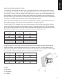
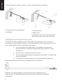
ENGLISH
TM-UST TECHMOUNT OWNERS MANUAL
TM-UST TECHMOUNT GUIDE DE L’UTILISATEUR
TM-UST TECHMOUNT MANUAL DE USUARIO
TM-UST TECHMOUNT GEBRUIKERSHANDLEIDING
BEDIENUNGSANLEITUNG TM-UST TECHMOUNT
TM-UST TECHMOUNT MANUALE DEL PROPRIETARIO TM-UST
TM-UST TECHMOUNT: INSTRUKCJA OBSŁUGI
installation:innovation
ENGLISH
TM-UST TECHMOUNT OWNERS MANUAL
Congratulations on your choice of the Vision
TM-UST TECHMOUNT. In order to obtain the
best performance please be sure to read this
owner’s manual and use your product only in
accordance with the instructions. An electronic
version of this manual and further information
can be found on www.visionaudiovisual.com
CONFORMITY
The product described in this owner’s
manual is in compliance with RoHS (EU
directive 2002/95/EC), and WEEE
(EU directive 2002/96/EC) standards.
Certificates including SGS reports are
available on request. This product should be
returned to the place of purchase at the end
of its useful life for recycling.
WARNINGS
During installation take care to adhere to workplace health and safety laws:
• Attach the bracket to a rated load-bearing structure.
• Do not cut or drill any parts above head height. This should all be done using the correct
safety equipment at floor level.
• Avoid overstretching which might result in the ladder tipping over.
• SWL (safe working load): 7.5kg (4.5kg if using extension pole)
THE ST8 WALL FIXTURES PROVIDED ARE ONLY FOR ATTACHMENT TO APPROPRIATE
SOLID WALLS – NOT HOLLOW WALLS. ALWAYS USE THE APPROPRIATE FIXTURES.
VISION DOES NOT ACCEPT LIABLITY FOR DETTACHMENT FROM THE WALL EITHER BY
INSTALLATION WITH INADEQUATE FIXTURES OR OVERLOADING.
Packaging
Save all packing material. It is essential for shipping in the event the unit ever needs repair.
IF ORIGINAL PACKAGING IS NOT USED TO RETURN THE UNIT TO THE SERVICE CENTRE,
DAMAGE IN TRANSIT WILL NOT BE COVERED BY WARRANTY.
1
ENGLISH
Contents
1 x 2-part Boom Assembly
1 x Wall Assembly
1 x Universal Spider Fitting
1 x H50 Pin-Hex key
4 x M2.5 43mm pan slot for Optoma & Acer
4 x M3 43mm screws
4 x M4 43mm screws
4 x M5 43mm screws
4 x M6 43mm screws
6 x ST8 50mm Ceiling Fixtures with rawl plugs for wall attachment
1 x 2-part Wall Plate Cover
6 x Wall Plate Inserts
1 x Boom Cover
Bracket Parts
1. Bolts
2. Wall Plate
3. Boom Part – section 1
4. Boom Part – section 2
5. Universal “Spider” Fitting
2
ENGLISH
INSTALLATION INSTRUCTIONS
1. Attach the wall plate to the wall using six appropriate fixtures. When you have attached
the wall plate you will have 170mm of height adjustment, but it is still important to position
it carefully. In rooms with low ceilings the height you can mount the screen/whiteboard will
be limited by the ceiling height so the bracket should be mounted as close to the ceiling as
possible. Where you have plenty of ceiling height, you should mount the screen/whiteboard
in place first to determine where the TM-UST should be positioned.
Most interactive whiteboards have side-to-side adjustment when in place, and the TM-UST
has ample up/down adjustment. Read the projector’s manual for advice.
For the Hitachi CP-A range of ultra short throw projectors the wall plate should be 100mm
to the right of the centre of the whiteboard/screen as you look at the wall. The chart below
gives approximate guidelines for the distance between the bottom of the wall plate and the
top of the viewable screen surface for common screen and whiteboard sizes.
Screen Diagonal
(inches)
57
64
77
82
94
98
Screen Width
(mm)
1158
1300
1565
1666
1910
1991
Bracket Distance
(mm)
170
190
240
290
300
320
For the Sanyo PLC-XE50 ultra short throw projector the wall plate should be 80mm to the
left of the centre of the whiteboard/screen as you look at the wall. The chart below gives
approximate guidelines for the distance between the bottom of the wall plate and the top of
the viewable screen surface for common screen and whiteboard sizes.
Screen Diagonal
(inches)
77
80
82
94
98
Screen Width
(mm)
1565
1626
1666
1910
1991
Bracket Distance
(mm)
260
270
280
320
340
1. Wall
2. Wall plate
3. Rawl plugs
4. ST8 Bolts
3
ENGLISH
2. Fit section 1 of the boom to the
wall plate, and fix tightly using the
four pin-hex bolts included.
1. Section 1 of boom
3. Fit the universal “spider” fitting included to the projector as shown by threading the
43mm screws included through the hollow screw already in place on each “leg” of the
spider. The Hitachi requires M6 screws, and the Sanyo requires M4. Other screw sizes
are included to cater for other projectors.
Fit the spider to section 2 of the boom as shown:
1. Universal “Spider” Fitting
2. Projector
3. Section 2 of boom
4. Take the assembled parts above and slide section 2 of the boom into section 1 as
shown below.
If the screen/whiteboard is very small (for
example 57” diameter) you will need to
insert section 2 projector-end first so that
the projector faces away from the wall,
then turn the projector 180 degrees.
1. Section 1 of boom
2. Section 2 of boom
4
ENGLISH
5. Plug power into the projector and turn it on. Follow these steps to setup the projector:
1. Adjust the boom length so that the projected image matches the screen WIDTH (don’t
worry about height yet), making sure the projector lens is exactly in the centre of the
screen.
Note once you have done this adjustment for screens/whiteboards less than 77”
(diameter) or 1500mm (wide), section 1 may protrude beyond the rear of the projector
and may require shortening. In this case follow this process:
1. Mark the excess length of section 1
2. Remove the projector and section 2 assembly from section 1
3. Cut section 1 shorter with a hacksaw at the projector end.
Lock section 2 into position with the locking pin-hex bolts on the top surface of section 1.
2. Use a spirit level and the hollow adjustment screws in the end of each spider leg to
make sure the projector is level.
3. Turn the wall plate adjustment bolt (shown below) to move the boom up or down as
required. If the screen is not perfectly flat and perpendicular to the projector lens the
projected image may not perfectly fit the screen. In which case make small adjustments
to the spider adjustment screws if necessary. Large adjustments will result in a poor
image.
1. Up/Down adjustment bolt (accessible
from the top or bottom of the wall plate)
Once all adjustments are made, insert the pin-hex bolts that lock the boom in place to the
wall plate.
5
ENGLISH
7. Route the power and inputs cables as shown and clip the covers into place:
1. Cable routing at top and bottom
of wall plate
1. Wall plate cover
2. Boom cover
3. Wall plate inserts (use to cover the boom
adjustment range hole on the wall cover)
ALTERNATIVE EXTENSION POLE FITTING
The TM-UST can be extended to up to 1.5m for short throw projectors. This is achieved
by fitting the extension pole to section 1, then fitting section 2 to the extension pole. To cut
excess length off the extension pole follow this process:
a.
Turn the projector on. Slide section 2 up and down the extension
pole into position so that the image matches the width of the screen/
whiteboard.
b.
Mark the excess length of the extension pole
c.
Turn the projector off. Remove the projector and section 2 assembly from
the extension pole.
d.
Cut the extension pole shorter with a hacksaw at the projector end.
Replace the projector and section 2 assembly and finish installation.
WARNING: THE SAFE WORKING LOAD LIMIT WITH THE EXTENSION POLE IS
4.5KG. DO NOT FIT THE EXTENSION POLE TO SECTION 1 IF SECTION 1 HAS BEEN
SHORTENED.
6
ENGLISH
WARRANTY
This product comes with a 2-year return to base warranty, effective from the date of
purchase. This warranty applies only to the original purchaser and is not transferable.
For the avoidance of doubt, this will be taken from the information held by the appointed
national distributor at the point of sale. The liability of the manufacturer and its
appointed service company is limited to the cost of repair and or replacement of the
faulty unit under warranty, except for death or injury (EU85/374/EEC). This warranty
protects you against the following:
• Faulty wields resulting in the product not safely performing its task within the
recommended SWL (safe working load).
• Poor fi nishing resulting in the product not being able to be assembled.
• External corrosion if identifi ed within 24 hours of purchase.
If you find you do have a problem with this product, you should contact the AV reseller
you purchased this product from. The original purchaser is responsible for shipment of
the product to the manufacturer’s appointed service centre for repair.
We will endeavour to return repaired units within 5 working days, however this may not
always be possible in which case it will be returned as soon as practically possible. This
warranty does not protect this product against faults caused by abuse, misuse, or incorrect installation which might be caused by ignoring the guidelines set out in this manual.
If failure is not covered by this warranty, the owner will be given the option to pay for
labour and parts to repair the unit at the service company’s standard rate.
7
8
FRANÇAIS
TM-UST TECHMOUNT GUIDE DE L'UTILISATEUR
Merci d'avoir acheté Vision TM-UST
TECHMOUNT. Afin d'obtenir les meilleures
performances du produit, s'assurer d'avoir
lu ce guide d'utilisateur et d'avoir respecté
les instructions avant son utilisation. Pour
télécharger la version électronique de ce
guide et obtenir plus d'informations, consulter
notre site Internet www.visionaudiovisual.com
CONFORMITÉ
Le produit décrit dans ce guide de
l'utilisateur est conforme à la RoHS (la
directive européenne 2002/95/EC) et à la
DEEE (la directive européenne 2002/96/
EC). Les certificats ainsi que les rapports
SGS sont disponibles sur demande. Ce
produit doit être retourné en magasin à la fin
de sa durée de vie pour recyclage.
AVERTISSEMENT
Lors de l'installation, se conformer aux conditions de sécurité et de santé sur le lieu de travail
suivantes :
• Fixer le support à une structure à charge nominale.
• Ne pas couper ni percer une pièce au-dessus de la hauteur de la tête. Afin de réaliser
cela, utiliser le bon
dispositif de protection au niveau du sol.
• Éviter toute extension de mouvement pouvant provoquer le déséquilibre de l'échelle.
• Charge maximale d'utilisation : 7.5kg (4.5kg avec l’extension pole)
LES DISPOSITIFS DE FIXATION AU MUR ST8 FOURNIS DOIVENT UNIQUEMENT ÊTRE
FIXÉS SUR DES MURS SOLIDES - PAS SUR DES MURS CREUX. TOUJOURS UTILISER LES
DISPOSITIFS DE FIXATION APPROPRIÉS. VISION DÉCLINE TOUTE RÉSPONSABILITÉ
CONCERNANT TOUT DÉTACHEMENT DU MUR CAUSÉ PAR UN DISPOSITIF DE FIXATION
INADÉQUAT OU SURCHARGÉ.
EMBALLAGE
Conserver l'emballage. Il sera indispensable en cas de renvoi de l'unité pour la réparation.
Tout dommage éventuel survenant lors du transport de l'unité ne sera pas couvert par la
garantie en cas de non-utilisation de l'emballage d'origine.
9
FRANÇAIS
Éléments
1 support mobile en deux pièces
1 ensemble mural
1 support-étoile universel
1 boulon de sécurité « pin-hex »
4 x vis à tête cylindrique large fendue M2,5 de 43 mm d'Optoma & Acer
4 vis M3 de 43 mm
4 vis M4 de 43 mm
4 vis M5 de 43 mm
4 vis M6 de 43 mm
6 plafonniers à crochets pour fixation murale
1 couvercle en deux pièces pour la plaque murale
6 douilles filetées pour la plaque murale
1 couvercle pour le support mobile
Pièces du support de fixation
1. Boulons
2. Plaque murale
3. Partie 1 du support mobile
4. Partie 2 du support mobile
5. Support-étoile universel
10
1. Fixer la plaque murale au mur en utilisant les dispositifs de fixation appropriés. Après
avoir fixé la plaque murale, on obtient un ajustement vertical de 170 mm, mais il est toujours
nécessaire de la positionner soigneusement. La hauteur nécessaire pour monter l'écran /
le tableau blanc sera limitée dans les pièces ayant un plafond bas. Il faut donc installer le
support de fixation le plus près possible du plafond. Il est préférable de monter l'écran / le
tableau blanc en premier dans les pièces ayant une hauteur de plafond suffisante afin de
déterminer le positionnement du TM-UST.
La plupart des tableaux blancs interactifs possèdent un ajustement côte à côte une fois mis
en place. De plus, le TM-UST possède un ajustement bas / haut. Consulter le guide du
projecteur pour plus d'informations.
En ce qui concerne la gamme de projecteurs à projection ultra courte Hitachi CP-A, la
plaque murale doit être placée à 100 mm à droite du centre de l'écran / du tableau blanc.
Le tableau ci-dessous donne un aperçu des distances approximatives entre le bas de la
plaque murale et le haut du champ de vision de l'écran en ce qui concerne les écrans et les
tableaux blancs ayant une taille normale.
Écran Diagonal
(pouce)
57
64
77
82
94
98
Écran Largeur
(mm)
1158
1300
1565
1666
1910
1991
Support distance
(mm)
170
190
240
290
300
320
En ce qui concerne la gamme de projecteurs à projection ultra courte Sanyo PLC-XE50, la
plaque murale doit être placée à 80 mm à gauche du centre de l'écran / du tableau blanc.
Le tableau ci-dessous donne un aperçu des distances approximatives entre le bas de la
plaque murale et le haut du champ de vision de l'écran en ce qui concerne les écrans et les
tableaux blancs ayant une taille normale.
Écran Diagonal
(pouce)
77
80
82
94
98
Écran Largeur
(mm)
1565
1626
1666
1910
1991
Support distance
(mm)
260
270
280
320
340
1. Mur
2. Plaque murale
3. Crochets
4. Boulons ST8
11
FRANÇAIS
INSTRUCTIONS D'INSTALLATION
FRANÇAIS
2. Insérer la partie 1 du support
mobile dans la plaque murale, puis
serrer fermement en utilisant les
boulons de sécurité « pin-hex ».
1. Partie 1 du
support mobile
3. Insérer le support-étoile universel fourni (voir illustration ci-dessous), puis fileter les vis
de 43 mm fournies dans les vis creuses déjà installées sur chaque « bras » du supportétoile. La marque Hitachi nécessite des vis de type M6 tandis que Sanyo nécessite des
vis de type M4. D'autres types de vis sont fournis pour une utilisation avec d'autres
marques de projecteurs.
Insérer le support-étoile sur la partie 2 du support mobile (voir illustration ci-dessous).
1. Support-étoile universel
2. Projecteur
3. Partie 2 du support mobile
4. Faire glisser la partie 2 du support mobile, qui se trouve avec les parties assemblées
ci-dessus, dans la partie 1 du support mobile (voir illustration ci-dessous).
Si l'écran / le tableau blanc est trop petit
(ex. : diamètre de 145 cm), il faut insérer
la partie 2 de l'extrémité du projecteur en
premier de façon à ce que le projecteur
soit dans le sens opposé au mur, ensuite
faire pivoter le projecteur de 180°.
1. Partie 1 du support mobile
2. Partie 2 du support mobile
12
FRANÇAIS
5. Brancher le projecteur à une source d'alimentation électrique et le mettre en marche.
Suivre les étapes d''installation du projecteur suivantes :
1. Ajuster la longueur du support mobile afin que la largeur de l'image projetée soit
égale à celle de l'écran (ne pas s'occuper de la hauteur pour l'instant) et s'assurer que
l'objectif se trouve exactement au centre de l'écran.
Noter que lorsque cet ajustement est effectué pour les écrans / tableaux blancs de moins
de 195 cm de diamètre ou de 1 500 mm de largeur, la partie 1 peut dépasser de la
partie arrière du projecteur et peut nécessiter un raccourcissement. Dans ce cas, suivre
les étapes suivantes :
1. Marquer la longueur qui dépasse de la partie 1
2. Retirer le projecteur et la partie 2 du support mobile de la partie 1
3. Couper le bout en trop de la partie 1 au niveau du marquage avec une
scie à métaux à l'extrémité du projecteur.
Fixer la partie 2 sur la partie supérieure de la partie 1 à l'aide des boulons de sécurité
« pin-hex ».
2. Utiliser un indicateur de niveau ainsi que les vis creuses d'ajustement à l'extrémité de
chaque bras du support-étoile afin de s'assurer que le projecteur est nivelé.
3. Tourner le boulon d'ajustement de la plaque murale (voir ci-dessous) pour déplacer le
support mobile vers le haut ou vers le bas si nécessaire. Si l'écran n'est pas totalement
plat et perpendiculaire par rapport à l'objectif du projecteur, l'image projetée peut ne
pas s'afficher correctement à l'écran. Dans certains cas, ajuster les vis d'ajustement du
support-étoile si nécessaire. Les ajustements poussés peuvent produire une mauvaise
image.
1. Boulon d'ajustement haut / bas
(accessible à partir de la partie
supérieure ou inférieure de la plaque
murale)
Après avoir effectué tous les ajustements, insérer les boulons de sécurité « pin-hex » pour
fixer le support mobile à la plaque murale.
13
FRANÇAIS
7. Passer les câbles d'entrée et d'alimentation (voir illustration ci-dessous), ensuite mettre le
couvercle.
1. Cheminement des câbles en haut
et en bas de la plaque murale
1. Couvercle de la plaque murale
2. Couvercle du support mobile
3. Douilles filetées de la plaque murale
(utilisées pour couvrir les trous d'ajustement
du support mobile sur le couvercle mural)
EXTENSION SUPPLÉMENTAIRE DU SUPPORT MOBILE
Le TM-UST peut être rallongé de plus de 1,5 m pour les projecteurs à projection courte.
Pour cela, insérer la barre d'extension dans la partie 1 du support mobile en premier,
insérer ensuite la partie 2 dans la barre d'extension. Afin d'éliminer la longueur
excédentaire de la barre d'extension, suivre les étapes suivantes :
a.
Mettre en marche le projecteur. Faire glisser la partie 2 vers le haut
et vers le bas de la barre d'extension afin que la largeur de l'image
projetée soit égale à celle de l'écran / du tableau blanc.
b.
Marquer la longueur excédentaire de la barre d'extension.
c.
Éteindre le projecteur. Retirer le projecteur et la partie 2 de la barre
d'extension.
d.
Couper le bout en trop de la barre d'extension au niveau du marquage
avec une scie à métaux à l'extrémité du projecteur.
Remettre le projecteur et la partie 2 et terminer l'installation.
AVERTISSEMENT : LA CHARGE MAXIMALE AUTORISÉE DE LA BARRE D'EXTENSION
EST DE 4.5KG. NE PAS INSÉRER LA BARRE D'EXTENSION DANS LA PARTIE 1 SI CETTE
DERNIÈRE A ÉTÉ RACCOURCIE.
14
FRANÇAIS
GARANTIE
Ce produit est garanti 2 ans à compter de la date
d'achat. La présente garantie s'applique uniquement à l'acheteur initial et n'est en aucun
cas cessible. Par soucis de clarté, cela sera repris par les informations détenues par le
distributeur national désigné
, que vous pouvez consulter au point de vente. La responsabilité du fabricant et de ses
sociétés de services désignées se limite aux frais de réparation ou de remplacement des
unités défectueuses sous garantie, sauf en cas de mort ou de blessure (EU85/374/EEC).
La présente garantie vous couvre en cas de :
• Utilisations inadaptées ayant pour conséquence que le produit n'effectue pas sa tâche
de manière sûre dans la limite de la
charge maximale d'utilisation recommandée.
• Mauvaise finition entraînant l'impossibilité d'assembler le produit.
• Corrosion externe si elle est découverte dans les 24 heures suivant l'achat.
Si vous rencontrez des problèmes avec ce produit, vous devez contacter le revendeur
audiovisuel
à qui vous avez acheté ce produit. L'acheteur initial est responsable du transport du
produit au centre de services désigné du fabricant pour réparation.
Nous ferons tout notre possible pour retourner les unités réparées dans un délai de
5 jours ouvrables. Toutefois, cela n'est pas toujours possible et, dans ce cas, nous les
retournerons dès que possible. La présente garantie ne couvre pas ce produit en cas de
défauts causés par une installation frauduleuse, inadaptée ou incorrecte qui peut être
causée par le non-respect des instructions exposées dans le présent guide.
Si le défaut n'est pas couvert par la présente garantie, l'utilisateur devra payer la main
d'œuvre et les pièces nécessaires pour réparer l'unité au tarif normal de la société de
services.
15
16
ESPAÑOL
MANUAL DEL PROPIETARIO DE TM-UST TECHMOUNT
Enhorabuena por haber adquirido el TM-UST
TECHMOUNT de Vision. A fin de obtener el
mejor rendimiento, le rogamos que lea este
manual del propietario y utilice el producto
únicamente de acuerdo con las instrucciones.
En el sitio Web www.visionaudiovisual.com
podrá encontrar una versión electrónica de
este manual, así como información adicional.
CONFORMIDAD
El producto que se describe en el presente
manual del propietario cumple las normas
RoHS (directiva de la UE 2002/95/CE)
y WEEE (directiva de la UE 2002/96/
CE). Previa petición, se pueden facilitar
los certificados, incluidos los informes
SGS. Este producto se debe devolver al
establecimiento de compra al final de su
vida útil para su reciclaje.
ADVERTENCIAS
Durante la instalación, debe respetar las leyes sobre seguridad y salud en el lugar de
trabajo:
• Coloque el soporte en una estructura que soporte la carga nominal.
• No corte ni perfore ninguna pieza situada por encima de la altura de la cabeza. Este
proceso se debe realizar con un equipo
de seguridad adecuado desde el nivel del suelo.
• Evite estirarse demasiado, ya que podría volcarse la escalera.
• SWL (carga segura de trabajo): 7.5kg (4.5kg con extensión polo)
LOS DISPOSITIVOS DE SUJECIÓN A LA PARED ST8 QUE SE PROPORCIONAN
ESTÁN DESTINADOS ÚNICAMENTE PARA SU COLOCACIÓN EN PAREDES SÓLIDAS
ADECUADAS, NO EN PAREDES HUECAS. UTILICE SIEMPRE DISPOSITIVOS DE
SUJECIÓN ADECUADOS. VISION NO ASUME NINGUNA RESPONSABILIDAD POR EL
DESPRENDIMIENTO DE LA PARED, YA SEA POR UNA INSTALACIÓN CON DISPOSITIVOS
DE SUJECIÓN INADECUADOS O POR UNA CARGA EXCESIVA.
Embalaje
Guarde todo el material de embalaje. Es fundamental para enviar el aparato en caso de
que sea necesario repararlo.
SI NO SE UTILIZA EL EMBALAJE ORIGINAL PARA DEVOLVER EL APARATO AL CENTRO DE
SERVICIO, LA GARANTÍA NO CUBRIRÁ LOS DAÑOS QUE SE PRODUZCAN DURANTE EL
TRANSPORTE.
17
ESPAÑOL
Contenido
1 x Conjunto de montaje del brazo 2 piezas
1 x Conjunto de montaje en la pared
1 x Accesorio de cruceta universal
1 x Llave macho hexagonal H50
4 x Tornillo de cabeza plana con ranura M2.5 43 mm para Optoma y Acer
4 x Tornillos M3 43 mm
4 x Tornillos M4 43 mm
4 x Tornillos M5 43 mm
4 x Tornillos M6 43 mm
6 x Dispositivos de sujeción para el techo ST8 50 mm con tacos para colocación
en la pared
1 x Cubierta de la placa de pared 2 piezas
6 x Piezas de inserción en la placa de pared
1 x Cubierta del brazo
Piezas del soporte
1. Pernos
2. Placa de pared
3. Pieza del brazo - sección 1
4. Pieza del brazo - sección 2
5. Accesorio de cruceta universal
18
ESPAÑOL
INSTRUCCIONES DE INSTALACIÓN
1. Acople la placa de pared a la pared con seis dispositivos de sujeción adecuados.
Cuando haya colocado la placa de pared dispondrá de 170 mm para ajustar la altura,
aunque es importante colocarla con cuidado. En estancias con techos bajos, la altura a
la que puede montar la pantalla/pizarra electrónica está limitada por la altura del techo.
Por lo tanto, el soporte se debe montar lo más cerca del techo que sea posible. Cuando
se dispone de mucha altura hasta el techo, se debe montar primero la pantalla/pizarra
electrónica para determinar dónde se debe colocar el TM-UST.
La mayoría de las pizarras electrónicas interactivas disponen de un ajuste lateral una vez
que están colocadas y el TM-UST permite realizar un amplio ajuste vertical. Lea el manual
del proyector para obtener información.
Para la gama Hitachi CP-A de proyectores de distancia ultracorta, la placa de pared debe
estar situada a 100 mm hacia la derecha respecto al centro de la pizarra electrónica/
pantalla estando situados de cara a la pared. La tabla siguiente proporciona directrices
aproximadas sobre la distancia que debe haber entre la parte inferior de la placa de pared
y la parte superior de la superficie visible de la pantalla para los tamaños más comunes de
pantallas y pizarras electrónicas.
Pantalla Diágonal
(pulgadas)
57
64
77
82
94
98
Pantalla Ancho
(mm)
1158
1300
1565
1666
1910
1991
Soporte Distancia
(mm)
170
190
240
290
300
320
Para el proyector Sanyo PLC-XE50 de distancia ultracorta, la placa de pared debe
estar situada a 80 mm hacia la izquierda respecto al centro de la pizarra electrónica/
pantalla estando situados de cara a la pared. La tabla siguiente proporciona directrices
aproximadas sobre la distancia que debe haber entre la parte inferior de la placa de pared
y la parte superior de la superficie visible de la pantalla para los tamaños más comunes de
pantallas y pizarras electrónicas.
Pantalla Diágonal
(pulgadas)
77
80
82
94
98
Pantalla Ancho
(mm)
1565
1626
1666
1910
1991
Soporte Distancia
(mm)
260
270
280
320
340
1. Pared
2. Placa de pared
3. Tacos
4. Pernos ST8
19
ESPAÑOL
2. Coloque la sección 1 del brazo
en la placa de pared y sujétela
con firmeza utilizando los cuatro
pasadores hexagonales que se
incluyen.
1. Sección 1 del brazo
3. Coloque el accesorio de cruceta universal que se incluye en el proyecto tal como
se muestra. Para ello, enrosque los tornillos de 43 mm que se incluyen en los tornillos
huecos que ya están colocados en cada "pie" del accesorio de cruceta. El modelo
Hitachi necesita tornillos M6 y el modelo Sanyo necesita M4. Se incluyen otros tamaños
de tornillos para cubrir las necesidades de distintos proyectores.
Coloque el accesorio de cruceta en la sección 2 del brazo, tal como se indica:
1. Accesorio de cruceta universal
2. Proyector
3. Sección 2 del brazo
4. Coja las piezas que acaba de montar y deslice la sección 2 del brazo en la sección 1,
tal como se indica a continuación.
Si la pantalla/pizarra eléctrica es muy
pequeña (por ejemplo, 57” de diámetro),
será necesario insertar primero el extremo
del proyector de la sección 2 de forma
que el proyector no quede orientado
hacia la pared y, a continuación, girar el
proyector 180 grados.
1. Sección 1 del brazo
2. Sección 2 del brazo
20
ESPAÑOL
5. Conecte el proyector a la alimentación eléctrica y enciéndalo. Siga estos pasos para
configurar el proyector:
1. Ajuste la longitud del brazo de forma que la imagen proyectada coincida con el
ANCHO de la pantalla (no se preocupe por la altura todavía) y compruebe que la lente
del proyector está situada justo en el centro de la pantalla.
Tenga en cuenta que cuando realiza este ajuste con pantallas/pizarras eléctricas de
menos de 77” (diámetro) o 1500 mm (ancho), la sección 1 puede sobresalir por la
parte posterior del proyector y puede ser necesario acortarla. Si este es el caso, realice
el proceso siguiente:
1. Marque la longitud que sobra de la sección 1.
2. Retire de la sección 1 el proyector y el montaje de la sección 2.
3. Corte la sección 1 con una sierra para metales por el extremo del proyector.
Fije en su sitio la sección 2 con los pasadores hexagonales de bloqueo en la superficie
superior de la sección 1.
2. Utilice un nivel de aire y los tornillos huecos de ajuste situados en el extremo de cada
pie del accesorio de cruceta para asegurarse de que el proyector está nivelado.
3. Gire el perno de ajuste de la placa de pared, que se muestra a continuación, para
mover el brazo hacia arriba o hacia abajo según sea necesario. Si la pantalla no
está totalmente plana y perpendicular a la lente del proyector, puede que la imagen
proyectada no quede encuadrada a la perfección en la pantalla. En este caso, realice
pequeños ajustes en los tornillos de ajuste del accesorio de cruceta si fuese necesario.
Los ajustes grandes provocarían que la imagen fuese de poca calidad.
1. Perno de ajuste vertical, al que se
puede acceder desde la parte superior o
inferior de la placa de pared.
Una vez que se hayan realizado todos los ajustes, inserte los pasadores hexagonales
que mantienen el brazo sujeto a la placa de pared.
21
ESPAÑOL
7. Guíe los cables de electricidad y de entrada tal como se indica y coloque las tapas en
su sitio:
1. Recorrido del cable en la parte
superior e inferior de la placa de pared.
1. Tapa de la placa de pared.
2. Tapa del brazo.
3. Inserciones de la placa de pared, que se
utilizan para cubrir el orificio del rango de
ajuste del brazo en la tapa de la pared.
COLOCACIÓN DEL VÁSTAGO DE EXTENSIÓN ALTERNATIVO
El TM-UST se puede alargar hasta 1,5 m para proyectores de distancia corta. Esto
se consigue colocando un vástago de extensión en la sección 1 y acoplando, a
continuación, la sección 2 en el vástago de extensión. Para cortar la longitud que sobre
del vástago de extensión realice el proceso siguiente:
a.
Encienda el proyector. Deslice la sección 2 hacia arriba y hacia abajo
por el vástago de extensión hasta que esté en su sitio de forma que la
imagen coincida con el ancho de la pantalla/pizarra electrónica.
b.
Marque la longitud que sobra del vástago de extensión.
c.
Apague el proyector. Retire del vástago de extensión el proyector y el
montaje de la sección 2.
d.
Corte el vástago de extensión con una sierra para metales por el
extremo del proyector.
Vuelva a colocar el proyector y el montaje de la sección 2 y complete la instalación.
ADVERTENCIA: EL LÍMITE DE CARGA DE TRABAJO SEGURA CON EL VÁSTAGO DE
EXTENSIÓN ES DE 4.5KG. NO ACOPLE EL VÁSTAGO DE EXTENSIÓN EN LA SECCIÓN
1 SI ÉSTA SE HA ACORTADO.
22
ESPAÑOL
GARANTÍA
Este producto incluye una garantía de devolución de dos años que entra en
vigor a partir de la fecha de compra. Esta garantía sólo se aplica al comprador
original y no es transferible. Para evitar cualquier duda, este dato se obtendrá de la
información que posee el distribuidor
nacional designado en el punto de venta. La responsabilidad del fabricante y su
empresa de mantenimiento designada está limitada en virtud de la garantía al coste de
la reparación o a la sustitución del aparato defectuoso, salvo en casos de fallecimiento
o lesión (UE85/374/CEE). Esta garantía cubre lo siguiente:
• Rendimiento defectuoso que provoca que el producto no funcione de forma segura
dentro de las recomendaciones de carga segura de trabajo.
• Acabado defectuoso que impida montar el producto.
• Corrosión externa si se detecta en un plazo de 24 horas desde la fecha de compra.
Si percibe que el producto presenta algún problema, debe ponerse en contacto con
el distribuidor de AV al que adquirió el producto. El comprador original es responsable
de enviar el producto al centro de mantenimiento designado por el fabricante para su
reparación.
Haremos todo lo posible por devolver los productos reparados en 5 días laborables, si
bien no siempre es posible y, en ese caso, se devolverá tan pronto como sea factible.
Esta garantía no cubre los fallos del producto causados por una utilización excesiva o
indebida ni por una instalación incorrecta, que pueda deberse a no haber tenido en
cuenta las directrices que se indican en este manual.
Si el fallo no está cubierto por la garantía, el propietario dispondrá de la opción de
pagar los costes de mano de obra y material para reparar el aparato al precio estándar
de la empresa de mantenimiento.
23
24
NEDERLANDS
TM-UST TECHMOUNT GEBRUIKERSHANDLEIDING
Gefeliciteerd met uw aankoop van de Vision
TM-UST TECHMOUNT. Lees deze gebruikershandleiding en gebruik uw product alleen in
overeenstemming met de aanwijzingen voor
een optimale prestatie. U vindt een elektronische versie van deze handleiding en verdere
informatie op www.visionaudiovisual.com
NALEVING
Het product dat beschreven wordt in deze
gebruikershandleiding voldoet aan de
normen van EU-richtlijn 2002/95/EG
betreffende de beperking van het gebruik
van bepaalde gevaarlijke stoffen (RoHS)
en EU-richtlijn 2002/96/EG betreffende
afgedankte elektrische en elektronische
apparatuur (AEEA). Certificaten, waaronder
de SGS-rapporten, zijn op aanvraag
verkrijgbaar. Aan het einde van de
levensduur dient dit product voor recycling
naar de plaats van aankoop te worden
teruggebracht.
WAARSCHUWINGEN
Houd bij de installatie rekening met de gezondheids- en veiligheidsvoorschriften voor op de
werkvloer:
• Bevestig de steun aan een vaste gewichtdragende structuur.
• Snijd en boor niet in plaatsen die zich boven uw hoofd bevinden. Al deze werkzaamheden dienen uitgevoerd te worden met de juiste
veiligheidsuitrusting vlak boven de vloer.
• Strek u niet te ver uit, omdat de ladder dan kan wegglijden.
• VWL (veilige werklading): 7.5kg (4.5kg met de extensie pole)
DE MEEGELEVERDE ST8-MUURBEVESTIGINGSMATERIALEN ZIJN ALLEEN GESCHIKT VOOR
BEVESTIGING AAN BLINDE MUREN, NIET VOOR SPOUWMUREN. GEBRUIK ALTIJD DE
JUISTE BEVESTIGINGSMATERIALEN. VISION IS NIET AANSPRAKELIJK VOOR LOSRAKEN
VAN DE MUUR DOOR INSTALLATIE MET ONGESCHIKTE BEVESTIGINGSMATERIALEN OF
DOOR OVERBELADING.
Verpakking
Bewaar alle verpakkingsmaterialen. Dit is belangrijk voor het geval dat het product ter
reparatie moet worden verzonden.
INDIEN HET ONDERDEEL NIET IN ZIJN ORIGINELE VERPAKKING WORDT
TERUGGESTUURD NAAR HET SERVICECENTRUM, WORDT ONDERWEG OPGELOPEN
SCHADE NIET DOOR DE GARANTIE GEDEKT.
25
NEDERLANDS
Inhoud
1 x 2-delige armassemblage
1 x muurassemblage
1 x universeel 'spin' hulpstuk
1 x H50 Pin zeshoekige ringsleutel
4 x M2.5 43mm kruiskopschroef voor Optoma & Acer
4 x M3 43mm schroeven
4 x M4 43mm schroeven
4 x M5 43mm schroeven
4 x M6 43mm schroeven
6 x ST8 50mm plafondbevestingsmaterialen met plugs voor bevestiging aan de muur
1 x 2-delig muurplaatdeksel
6 x muurplaatinzetstukken
1 x armplaat
Onderdelen steun
1. Bouten
2. Muurplaat
3. Onderdeel arm – sectie 1
4. Onderdeel arm – sectie 2
5. Universeel 'spin' hulpstuk
26
NEDERLANDS
INSTALLATIE-INSTRUCTIES
1. Bevestig de muurplaat met de zes juiste bevestigingsmaterialen aan de muur. Nadat u
de muurplaat heeft bevestigd, is er nog een verticale speling van 170 mm. Het blijft echter
belangrijk dat u de muurplaat zorgvuldig op zijn plaats brengt. Indien u laag plafond heeft,
is er maar beperkte ruimte om het scherm/whiteboard op te hangen, dus dient u de steun zo
dicht mogelijk onder het plafond te hangen. Als het plafond hoog genoeg is, dient u eerst
het scherm/whiteboard op te hangen om te bepalen waar de TM-UST moet komen.
De meeste interactieve whiteboards kunnen aan beide kanten worden aangepast zodra ze
op hun plaats hangen. Bovendien biedt de TM-UST voldoende mogelijkheid om verticaal te
worden aangepast. Lees de handleiding van de projector voor advies.
Bij de Hitachi CP-A-reeks van Ultra Short Throw projectoren dient de muurplaat 100 mm
rechts van het midden van het whiteboard/scherm te zijn geplaatst als je naar de muur kijkt.
Onderstaande tabel geeft bij benadering richtlijnen voor de afstand tussen de onderkant van
de muurplaat en de bovenkant van het zichtbare schermoppervlak voor standaardmaten van
schermen en whiteboards.
Scherm Diagonaal
(inches)
57
64
77
82
94
98
Scherm Breedte
(mm)
1158
1300
1565
1666
1910
1991
Steun Afstand
(mm)
170
190
240
290
300
320
Bij de Sanyo PLC-XE50 Ultra Short Throw projector dient de muurplaat 80 mm links
van het midden van het whiteboard/scherm te zijn geplaatst als je naar de muur kijkt.
Onderstaande tabel geeft bij benadering richtlijnen voor de afstand tussen de onderkant van
de muurplaat en de bovenkant van het zichtbare schermoppervlak voor standaardmaten van
schermen en whiteboards.
Scherm Diagonaal
(inches)
77
80
82
94
98
Scherm Breedte
(mm)
1565
1626
1666
1910
1991
Steun Afstand
(mm)
260
270
280
320
340
1. Muur
2. Muurplaat
3. Pluggen
4. ST8-bouten
27
NEDERLANDS
2. Bevestig sectie 1 van de arm
stevig aan de muurplaat met de
vier meegeleverde Pin zeshoekige
bouten.
1. Sectie 1 van arm
3. Bevestig het universele 'spin' hulpstuk dat bij de projector is meegeleverd door de
meegeleverde 43 mm schroeven door de holle schroeven te steken die zich al in elke
'poot' van de spin bevinden (zie afbeelding). Voor de Hitachi zijn M6-schroeven nodig
en voor de Sanyo M4-schroeven. De overige meegeleverde schroefmaten zijn bedoeld
voor andere projectoren.
Bevestig de spin aan sectie 2 van de arm zoals afgebeeld:
1. Universeel 'spin' hulpstuk
2. Projector
3. Sectie 2 van arm
4. Pak de hierboven gemonteerde onderdelen en schuif sectie 2 van de arm in sectie 1,
zoals hieronder afgebeeld.
Als het scherm/whiteboard erg klein is
(bijvoorbeeld 57” diameter), dient u eerst
het projectoreinde van sectie 2 erin te
schuiven zodat de projector van de muur
af staat. Draai de projector vervolgens
180 graden.
1. Sectie 1 van arm
2. Sectie 2 van arm
28
NEDERLANDS
5. Steek de stekker in de projector en zet hem aan. Volg deze stappen om de projector in
te stellen:
1. Pas de armlengte aan, zodat het geprojecteerde beeld net zo groot is als de
BREEDTE van het scherm (let nog niet op de hoogte). Zorg er daarbij voor dat de lens
van de projector zich precies in het midden van het scherm bevindt.
Let op: als u deze aanpassing eenmaal hebt uitgevoerd voor schermen/whiteboards
kleiner dan 77” (diameter) of 1500mm (breedte) kan sectie 1 aan de achterkant van de
projector uitsteken. U dient deze dan in te korten. Doe in dat geval het volgende:
1. Markeer het uitstekende gedeelte van sectie 1
2. Verwijder de projector en de sectie 2-assemblage van sectie 1
3. Snijd met een metaalzaag een deel van sectie 1 af aan het einde van
de projector.
Klem sectie 2 bovenop sectie 1 met de Pin zeshoekige bouten.
2. Gebruik een waterpas en de holle bevestigingsschroeven aan het eind van iedere
poot van de spin om ervoor te zorgen dat de projector waterpas staat.
3. Draai de bout wat losser van de muurplaat (zoals hieronder) om de arm naar
behoefte omhoog of omlaag te verschuiven. Als het scherm niet volledig vlak en
loodrecht ten opzichte van de projectorlens staat, kan het zijn dat het geprojecteerde
beeld niet perfect op het scherm past. Maak dan, indien nodig, wat kleine aanpassingen
aan de 'spin' schroeven. Grote aanpassingen zullen resulteren in een slecht beeld.
1. Omhoog/Omlaag aanpasbare bout
(bereikbaar vanaf de boven- of onderkant
van de muurplaat)
Breng, wanneer alle aanpassingen zijn gemaakt, de Pin zeshoekige bouten aan die de
arm op de juiste plaats op de muurplaat klemmen.
29
NEDERLANDS
7. Leid de stroom- en invoerkabels zoals op de afbeelding en klem de deksels weer op hun
plaats:
1. Kabelgeleiding aan de boven- en
onderkant van de muurplaat
1. Muurplaatdeksel
2. Armdeksel
3. Muurplaatinzetstukken (gebruikt om de
gaten voor de armaanpassingen op het
muurdeksel af te dekken)
ALTERNATIEVE BEVESTIGING MET VERLENGSTUK
De TM-UST kan tot 1,5 m verlengd worden voor Short Throw projectoren. Dit wordt bereikt
door het verlengstuk op sectie 1 te monteren en vervolgens sectie 2 op het verlengstuk.
Om het uitstekende deel van het verlengstuk af te snijden doet u het volgende:
a.
Zet de projector aan. Schuif sectie 2 heen en weer op het verlengstuk
totdat het beeld net zo breed is als het scherm/whiteboard.
b.
Markeer het uitstekende gedeelte van het verlengstuk
c.
Zet de projector uit. Verwijder de projector en de sectie 2-assemblage
van het verlengstuk.
d.
Snijd met een metaalzaag een deel van het verlengstuk af aan het einde
van de projector.
Plaats de projector en de sectie 2-assemblage weer terug en maak de installatie af.
WAARSCHUWING: DE VEILIGE WERKLADING VAN HET VERLENGSTUK IS 4.5KG.
BEVESTIG HET VERLENGSTUK NIET AAN SECTIE 1 ALS SECTIE 1 IS INGEKORT.
30
NEDERLANDS
GARANTIE
Dit product heeft een retourgarantie van twee jaar beginnend op de dag van
aankoop. Deze garantie geldt alleen voor de oorspronkelijke koper en kan niet worden
overgedragen. Om enige twijfel te voorkomen is deze informatie gebaseerd op de informatie van de aangewezen
nationale distributeur op het verkooppunt. De aansprakelijkheid van de fabrikant en
diens
aangewezen servicebedrijf is beperkt tot de reparatiekosten en/of vervanging van het
defecte apparaat waarvoor deze garantie geldt, behalve in geval van overlijden of letsel
(EU85/374/EEG). Deze garantie beschermt u tegen:
• Verkeerd gebruik waardoor het product niet veilig werkt binnen de
aanbevolen VWL (veilige werklading).
• Slechte afwerking waardoor het product niet gemonteerd kan worden.
• Externe corrosie wanneer dit binnen 24 uur na aankoop wordt vastgesteld.
Indien u toch problemen met dit product ondervindt, dient u contact op te nemen met de
elektronicazaak
waar u dit product heeft gekocht. De oorspronkelijke koper is verantwoordelijk voor de
verzending van het product naar het door de fabrikant aangewezen servicecentrum.
Wij zullen proberen de gerepareerde onderdelen binnen vijf werkdagen terug te sturen.
Dit is echter niet altijd mogelijk. In dat geval sturen wij het gerepareerde onderdeel zo
snel als mogelijk is terug. Deze garantie beschermt het product niet tegen gebreken
veroorzaakt door misbruik, verkeerd gebruik of onjuiste installatie welke het gevolg kan
zijn van het niet naleven van de richtlijnen in deze handleiding.
Indien het gebrek niet door deze garantie wordt gedekt, heeft de eigenaar de mogelijkheid om voor de arbeidsuren en de gerepareerde onderdelen te betalen tegen het
standaardtarief van het servicebedrijf.
31
32
DEUTSCHE
BEDIENUNGSANLEITUNG TM-UST TECHMOUNT
Herzlichen Glückwunsch zum Kauf des Vision
TM-UST TECHMOUNT! Um die bestmögliche
Funktionalität Ihres Produkts zu erzielen, lesen
Sie diese Bedienungsanleitung aufmerksam
durch und verwenden Sie das Produkt entsprechend den gegebenen Anweisungen. Unter
www.visionaudiovisual.com finden Sie die
elektronische Version dieser Bedienungsanleitung sowie weitere Informationen.
KONFORMITÄT
Das in dieser Bedienungsanleitung
beschriebene Produkt entspricht der EURichtlinie zur Beschränkung der Verwendung
bestimmter gefährlicher Stoffe in Elektround Elektronikgeräten (2002/95/EG)
sowie der EU-Richtlinie über Elektro- und
Elektronik-Altgeräte (2002/96/EG). Auf
Anfrage können Zertifikate (einschließlich
SGS-Berichten) eingesehen werden.
Dieses Produkt sollte nach Ablauf seiner
Lebensdauer beim Händler zurückgegeben
werden, um ein ordnungsgemäßes Recycling
zu ermöglichen.
WARNHINWEISE
Achten Sie darauf, dass bei der Montage die Bestimmungen zu Sicherheit und Gesundheitsschutz am Arbeitsplatz eingehalten werden:
• Befestigen Sie die Halterung an einer Wand, die zum Tragen von Lasten geeignet ist.
• Führen Sie keine Schneide- oder Bohrarbeiten über Kopfhöhe durch. Alle diese Arbeiten
sollten unter Verwendung geeigneter Sicherheitsausrüstung
auf Bodenhöhe ausgeführt werden.
• Vermeiden Sie Haltungen, bei denen Sie sich übermäßig strecken müssen, um ein Umkippen der Leiter zu verhindern.
• Tragfähigkeit: 7.5kg (4.5kg mit der endung-polig)
DIE MITGELIEFERTEN WANDBEFESTIGUNGEN ST8 SIND NUR FÜR DIE BEFESTIGUNG
AN GEEIGNETEN MASSIVWÄNDEN, NICHT ABER FÜR HOHLWÄNDE BESTIMMT.
VERWENDEN SIE IMMER GEEIGNETE BEFESTIGUNGEN. VISION ÜBERNIMMT KEINE
HAFTUNG FÜR SCHÄDEN, DIE DURCH EIN ABLÖSEN DER HALTERUNG VON DER
WAND ENTSTANDEN SIND, WELCHES DURCH DIE VERWENDUNG UNGEEIGNETER
BEFESTIGUNGEN ODER ÜBERLADUNG VERURSACHT WURDE.
Verpackung
Bewahren Sie das Verpackungsmaterial vollständig auf. Es wird für den Transport im
Reparaturfall benötigt.
WENN FÜR DEN TRANSPORT ZUM REPARATURZENTRUM NICHT DIE
ORIGINALVERPACKUNG VERWENDET WIRD, WERDEN EVENTUELLE
TRANSPORTSCHÄDEN NICHT VON DER GARANTIE ABGEDECKT.
33
DEUTSCHE
Lieferumfang
1 x 2-teiliges Armstück
1 x Wandstück
1 x universelle Spinnenhalterung
1 x H50 Stift-Inbus
4 x M2,5 43-mm-Linsenkopfschraube mit Schlitz für Optoma & Acer
4 x M3 43-mm-Schrauben
4 x M4 43-mm-Schrauben
4 x M5 43-mm-Schrauben
4 x M6 43-mm-Schrauben
6 x ST8 50-mm-Deckenbefestigungen mit Wanddübeln zur Wandmontage
1 x 2-teilige Wandplattenabdeckung
6 x Wandplatteneinsätze
1 x Armabdeckung
Halterungsteile
1. Schrauben
2. Wandplatte
3. Armteil – Abschnitt 1
4. Armteil – Abschnitt 2
5. Universelle Spinnenhalterung
34
DEUTSCHE
MONTAGEANLEITUNG
1. Bringen Sie die Wandplatte mit sechs dafür geeigneten Befestigungen an der Wand
an. Nach Anbringung der Wandplatte kann die Höhe noch um bis zu 170 mm verändert
werden. Dennoch ist bei der Positionierung auf größtmögliche Genauigkeit zu achten. In
niedrigen Räumen wird die maximale Höhe, in der die Bildwand/das Whiteboard befestigt
werden kann, von der Höhe der Decke bestimmt. Daher sollte die Halterung so nahe wie
möglich an der Decke angebracht werden. In hohen Räumen sollte zunächst die Bildwand/
das Whiteboard befestigt werden, damit anschließend die Positionierungshöhe des TM-UST
ermittelt werden kann.
Die meisten interaktiven Whiteboards können nach ihrer Montage seitlich verschoben
werden, zudem verfügt das TM-UST über einen großen Spielraum bei der Höhenverstellung.
Weitere Informationen hierzu finden Sie in der Bedienungsanleitung des Projektors.
Für Ultra-Nah-Projektoren der Serie CP-A von Hitachi sollte sich die Wandplatte 100 mm
rechts vom Mittelpunkt der Bildwand/des Whiteboards befinden (Blickrichtung zur Wand).
Die untenstehende Tabelle enthält Richtwerte für den Abstand zwischen der Unterkante der
Wandplatte und der Oberkante des sichtbaren Teils der Bildwand für gängige Bildwand- und
Whiteboard-Größen.
Bildwand
Bilddiagonale (zoll)
57
64
77
82
94
98
Bildwand
Breite (mm)
1158
1300
1565
1666
1910
1991
Halterung
Abstand (mm)
170
190
240
290
300
320
Für den Ultra-Nah-Projektor PLC-XE50 von Sanyo sollte sich die Wandplatte 80 mm links
vom Mittelpunkt der Bildwand/des Whiteboards befinden (Blickrichtung zur Wand). Die
untenstehende Tabelle enthält Richtwerte für den Abstand zwischen der Unterkante der
Wandplatte und der Oberkante des sichtbaren Teils der Bildwand für gängige Bildwand- und
Whiteboard-Größen.
Bildwand Bilddiagonale (zoll)
77
80
82
94
98
Bildwand Breite (mm)
1565
1626
1666
1910
1991
Halterung
Abstand (mm)
260
270
280
320
340
1. Wand
2. Wandplatte
3. Wanddübel
4. ST8 Schrauben
35
DEUTSCHE
2. Bringen Sie Abschnitt 1 des
Arms an der Wandplatte an und
befestigen Sie ihn mithilfe der vier
beiliegenden Stift-Inbusschrauben.
1. Armabschnitt 1
3. Verbinden Sie die beiliegende universelle Spinnenhalterung entsprechend der
Abbildung mit dem Projektor, indem Sie die beiliegenden 43 mm-Schrauben in die
Hohlschrauben eindrehen, die sich jeweils an einem Bein der Spinnenhalterung
befinden. Für den Projektor von Hitachi werden die M6-Schrauben benötigt, für
den Projektor von Sanyo die M4-Schrauben. Für andere Projektortypen sind weitere
Schraubengrößen im Lieferumfang enthalten.
Bringen Sie die Spinnenhalterung entsprechend der Abbildung an Abschnitt 2 des
Arms an:
1. Universelle Spinnenhalterung
2. Projektor
3. Armabschnitt 2
4. Nehmen Sie nun die vormontierten Teile und schieben Sie Abschnitt 2 des Arms in
Abschnitt 1, wie unten gezeigt.
Wenn die Bildwand/das Whiteboard sehr
klein ist (z. B. 57'' Bilddiagonale), müssen
Sie Abschnitt 2 mit dem Projektor-Ende
voran einführen, sodass der Projektor von
der Wand wegzeigt, und ihn dann um
180° drehen.
1. Armabschnitt 1
2. Armabschnitt 2
36
DEUTSCHE
5. Schließen Sie das Netzkabel am Projektor an und schalten Sie ihn ein. Befolgen Sie zur
Einstellung des Projektors die folgenden Schritte:
1. Wählen Sie die Armlänge so, dass das projizierte Bild die BREITE der Bildwand
vollständig ausfüllt (die Höhe wird in einem späteren Arbeitsschritt angepasst) und stellen
Sie sicher, dass sich die Linse des Projektors exakt in der Mitte der Bildwand befindet.
Beachten Sie, dass nach der Einstellung für Bildwände/Whiteboards mit einer
Bilddiagonalen von weniger als 77'' oder einer Breite von weniger als 150 cm Abschnitt
1 über das Ende des Projektors hervorstehen und eine Kürzung erforderlich machen
kann. Gehen Sie in diesem Fall wie folgt vor:
1. Markieren Sie den überstehenden Teil von Abschnitt 1.
2. Trennen Sie die Einheit aus Projektor und Abschnitt 2 von Abschnitt 1.
3. Kürzen Sie Abschnitt 1 am dem Projektor zugewandten Ende mit
einer Metallsäge.
Befestigen Sie Abschnitt 2 mithilfe der Stift-Inbus-Feststellschrauben an der
entsprechenden Position auf der Oberseite von Abschnitt 1.
2. Verwenden Sie eine Wasserwaage und die Einstell-Hohlschrauben am Ende jedes
Beins der Spinnenhalterung, um den Projektor waagrecht auszurichten.
3. Drehen Sie an der Wandplatteneinstellschraube (siehe unten), um das Armstück auf
die gewünschte Höhe zu bringen. Wenn die Bildwand nicht absolut eben bzw. lotrecht
zur Projektorlinse ist, ist es möglich, dass sich das projizierte Bild nicht vollständig mit
der Bildwandfläche deckt. Nehmen Sie in diesem Fall ggf. kleinere Korrekturen mithilfe
der Spinnenhalterungs-Einstellschrauben vor. Größere Korrekturen haben einen Verlust
der Bildqualität zur Folge.
1. Auf/ab-Einstellschraube (von der
Ober- oder Unterseite der Wandplatte
aus zugänglich)
Fixieren Sie nach Abschluss der Einstellungen die Stift-Inbusschrauben, die den Arm in
der Wandplatte halten.
37
DEUTSCHE
7. Führen Sie die Netz- und Eingangskabel entsprechend der Abbildung und setzen Sie
die Abdeckungen auf:
1. Kabelführung ober- und unterhalb
der Wandplatte
1. Wandplattenabdeckung
2. Armabdeckung
3. Wandplatteneinsätze (zur Abdeckung
des Armeinstellungslochs an der
Wandabdeckung)
ALTERNATIVE VERLÄNGERUNGSARMHALTERUNG
Das TM-UST kann für Ultra-Nah-Projektoren um bis zu 1,5 m verlängert werden. Hierfür
muss Abschnitt 1 mit dem Verlängerungsarm und dieser mit Abschnitt 2 verbunden
werden. Um den Verlängerungsarm auf das gewünschte Maß zu kürzen, gehen Sie wie
folgt vor:
a.
Schalten Sie den Projektor ein. Schieben Sie Abschnitt 2 am
Verlängerungsarm auf und ab, bis das Bild mit der Breite der Bildwand/
des Whiteboards übereinstimmt.
b.
Markieren Sie den überstehenden Teil des Verlängerungsarms.
c.
Schalten Sie den Projektor aus. Trennen Sie die Einheit aus Projektor und
Abschnitt 2 vom Verlängerungsarm.
d.
Kürzen Sie den Verlängerungsarm am dem Projektor zugewandten Ende
mit einer Metallsäge.
Bringen Sie die Einheit aus Projektor und Abschnitt 2 wieder an und schließen Sie die
Montage ab.
WARNHINWEIS: DIE MAXIMALE TRAGFÄHIGKEIT BEI VERWENDUNG DES
VERLÄNGERUNGSARMS BETRÄGT 4.5KG. BRINGEN SIE DEN VERLÄNGERUNGSARM
NICHT AN ABSCHNITT 1 AN, WENN ABSCHNITT 1 ZUVOR GEKÜRZT WURDE.
38
DEUTSCHE
GARANTIE
Auf dieses Produkt wird eine 2-jährige Rückgabegarantie ab
Kaufdatum gewährt. Diese Garantie gilt nur für den ursprünglichen Käufer und kann
nicht übertragen werden. Im Zweifelsfall wird dies anhand der Informationen entschieden, die dem für das jeweilige Land zuständigen
Vertragshändler am Verkaufsort vorliegen. Die Haftung des Herstellers und
des von ihm bestimmten Serviceunternehmens beschränkt sich auf die Reparaturkosten
und/oder den Ersatz des fehlerhaften Teils im Rahmen der Garantie; eine Ausnahme davon stellen Todesfälle und Körperverletzungen dar (EU-Richtlinie 85/374/EWG). Diese
Garantie umfasst folgende Punkte:
• Abbrechen oder Nachgeben der Konstruktion,
wodurch eine sichere Verwendung des Produkts innerhalb des empfohlenen Tragfähigkeitsbereichs nicht mehr möglich ist.
• Mangelhafte Verarbeitung, aufgrund derer das Produkt nicht montiert werden kann.
• Von außen erkennbare Roststellen, sofern diese innerhalb von 24 Stunden nach Kauf
beanstandet werden.
Wenn Sie ein Problem mit dem Produkt feststellen, wenden Sie sich an den AV-Händler,
bei dem Sie dieses Produkt gekauft haben. Der ursprüngliche Käufer ist für den Transport
des Produkts zu dem vom Hersteller bestimmten Reparaturzentrum verantwortlich.
Wir bemühen uns, reparierte Geräte innerhalb von fünf Werktagen an den Kunden
zurückzusenden. Sollte dies aufgrund gegebener Umstände nicht möglich sein, werden
wir selbstverständlich versuchen, das Gerät dennoch so schnell wie möglich zurückzusenden. Diese Garantie gilt nicht für Produktmängel, die durch unsachgemäßen oder
unachtsamen Gebrauch bzw. fehlerhafte Montage entstanden und beispielsweise auf
Missachtung der Hinweise in dieser Bedienungsanleitung zurückzuführen sind.
Im Falle eines Funktionsmangels, der nicht von dieser Garantie abgedeckt wird, hat der
Besitzer die Möglichkeit, das Produkt zum Standardpreis für Arbeits- und Ersatzteilkosten
bei dem für die Reparatur zuständigen Unternehmen reparieren zu lassen.
39
40
ITALIANO
TM-UST TECHMOUNT MANUALE DEL PROPRIETARIO
Congratulazioni per aver scelto TM-UST
TECHMOUNT di Vision. Per ottenere le
migliori prestazioni, leggere questo manuale
e utilizzare il prodotto seguendo attentamente
le istruzioni ivi riportate. Una versione
elettronica di questo manuale e ulteriori
informazioni sono reperibili all'indirizzo
www.visionaudiovisual.com
CONFORMITÀ
Il prodotto descritto in questo manuale è
conforme agli standard RoHS (direttiva
UE 2002/95/CE) e WEEE (direttiva UE
2002/96/CE). Le certificazioni, compresi i
rapporti SGS, sono disponibili su richiesta.
Al termine della sua vita utile, consegnare
questo prodotto al rivenditore per il
riciclaggio.
AVVERTENZE
Durante l'installazione, attenersi scrupolosamente alle leggi in materia di salute e sicurezza
sul posto di lavoro:
• Fissare la staffa a una struttura portante solida.
• Non tagliare o trapanare nessuna parte al di sopra dell'altezza della testa. Questo genere
di operazioni va eseguito al livello del pavimento
utilizzando l'attrezzatura antinfortunistica idonea.
• Durante l'utilizzo di scale, non allungarsi eccessivamente onde evitare il ribaltamento.
• SWL (safe working load: carico di lavoro massimo): 7.5kg (4.5kg con estensione polo)
I DISPOSITIVI DI FISSAGGIO A PARETE ST8 FORNITI A CORREDO SONO INDICATI
ESCLUSIVAMENTE PER PARETI PIENE, NON PER PARETI A CASSA VUOTA. UTILIZZARE
SEMPRE DISPOSITIVI DI FISSAGGIO IDONEI. VISION DECLINA OGNI RESPONSABILITÀ
IN CASO DI DISTACCO DALLA PARETE IMPUTABILE A INSTALLAZIONE CON DISPOSITIVI
DI FISSAGGIO NON IDONEI O A SOVRACCARICO.
Imballaggio
Conservare tutto l'imballaggio originale per la spedizione in caso di riparazioni dell'unità.
LA GARANZIA NON COPRE GLI EVENTUALI DANNI SUBITI DURANTE IL TRASPORTO SE
L'UNITÀ GIUNGE AL CENTRO DI ASSISTENZA SENZA IMBALLAGGIO ORIGINALE.
41
ITALIANO
Contenuto
1 x kit di montaggio per braccio a due elementi
1 x kit di montaggio per parete
1 x dispositivo di fissaggio universale a ragno
1 x chiave a brugola H50
4 x viti a taglio M2.5 di 43mm per Optoma e Acer
4 x viti M3 di 43mm
4 x viti M4 di 43mm
4 x viti M5 di 43mm
4 x viti M6 di 43mm
6 x dispositivi di fissaggio a soffitto ST8 di 50mm con tasselli per attacco a parete
1 x copertura per piastra a muro a due elementi
6 x inserti per piastra a muro
1 x copertura per il braccio
Parti della staffa
1. Bulloni
2. Piastra a muro
3. Parte della staffa – sezione 1
4. Parte della staffa – sezione 2
5. Dispositivo di fissaggio universale a ragno
42
ITALIANO
ISTRUZIONI PER L'INSTALLAZIONE
1. Fissare la piastra a muro alla parete mediante sei dispositivi di fissaggio idonei. Una
volta fissata la piastra a muro, sono disponibili 170mm per la regolazione dell'altezza,
ma è comunque importante posizionarla con attenzione. Negli ambienti con soffitto basso,
l'altezza a cui si può montare lo schermo/la lavagna bianca sarà limitata dall'altezza del
soffitto, pertanto la staffa dovrà essere montata il più vicino possibile al soffitto. Quando il
soffitto è alto, sistemare lo schermo/la lavagna bianca prima di stabilire dove posizionare il
TM-UST.
La maggior parte delle lavagne bianche interattive, una volta sistemate, possono essere
regolate lateralmente, mentre il TM-UST può essere ampiamente regolato in senso verticale.
Leggere il manuale del proiettore per suggerimenti in merito.
Per la serie di proiettori ultra short throw Hitachi CP-A, la piastra a muro dovrebbe essere
posta a 100mm a destra rispetto al centro della lavagna bianca/dello schermo guardando
verso la parete. La tabella sottostante fornisce linee guida indicative sulla distanza che
dovrebbe intercorrere tra la parte inferiore della piastra a muro e la parte superiore della
superficie guardabile dello schermo per schermi e lavagne di dimensioni normali.
Schermo Diagonale Schermo Ampiezza (policci)
(mm)
57
1158
64
1300
77
1565
82
1666
94
1910
98
1991
Staffa Distanza
(mm)
170
190
240
290
300
320
Per il proiettore ultra short throw Sanyo PLC-XE50, la piastra a muro dovrebbe essere posta
a 80mm a sinistra rispetto al centro della lavagna bianca/dello schermo guardando verso
la parete. La tabella sottostante fornisce linee guida indicative sulla distanza che dovrebbe
intercorrere tra la parte inferiore della piastra a muro e la parte superiore della superficie
guardabile dello schermo per schermi e lavagne di dimensioni normali.
Schermo Diagonale Schermo Ampiezza
(policci)
(mm)
77
1565
80
1626
82
1666
94
1910
98
1991
Staffa Distanza
(mm)
260
270
280
320
340
1. Parete
2. Piastra a muro
3. Tasselli
4. Bulloni ST8
43
ITALIANO
2. Montare la sezione 1 del braccio
alla piastra a muro e fissarla
saldamente con i quattro bulloni a
brugola.
1. Sezione 1 del braccio
3. Montare il dispositivo di fissaggio universale a ragno al proiettore come mostrato,
infilando le viti di 43mm fornite a corredo nella vite forata già posta su ogni "arto" del
dispositivo a ragno. Per Hitachi utilizzare viti M6, per Sanyo viti M4. Sono fornite viti di
altre dimensioni per diversi tipi di proiettori.
Adattare il dispositivo a ragno alla sezione 2 del braccio come mostrato:
1. Dispositivo di fissaggio universale stile
ragno
2. Proiettore
3. Sezione 2 della staffa
4. Prendere le parti montate sopra e far scorrere la sezione 2 del braccio nella sezione 1
come mostrato sotto.
Se lo schermo/la lavagna bianca è di
dimensioni ridotte (p.es. 57" di diametro)
sarà necessario collegare la sezione 2 al
proiettore prima, in modo che il proiettore
non guardi alla parete, quindi girare il
proiettore di 180 gradi.
1. Sezione 1 della staffa
2. Sezione 2 della staffa
44
ITALIANO
5. Collegare il proiettore alla corrente e accenderlo. Procedere come segue per impostare
il proiettore:
1. Regolare la lunghezza del braccio in modo che l'immagine proiettata corrisponda
all'AMPIEZZA dello schermo (per il momento trascurare l'altezza), assicurandosi che
l'obiettivo del proiettore sia esattamente al centro dello schermo.
Notare che, una volta effettuata questa regolazione, in caso di schermi/lavagne inferiori
a 77" (diametro) o a 1500mm (ampiezza), la sezione 1 potrebbe sporgere rispetto alla
parte posteriore del proiettore e potrebbe, pertanto, dover essere accorciata. In questo
caso, procedere nel seguente modo:
1. Segnare di quanto deve essere ridotta la lunghezza della sezione 1
2. Rimuovere il proiettore e la sezione 2 dalla sezione 1
3. Accorciare la sezione 1 con un seghetto per metalli
Fissare la sezione 2 sulla parte superiore della sezione 1 con i bulloni di bloccaggio a
brugola.
2. Usare una livella a bolla d'aria e le viti forate poste sulla parte terminale di ogni
"arto" del dispositivo a ragno per accertarsi che il proiettore sia dritto.
3. Girare il bullone di regolazione della piastra a muro (come mostrato sotto) per
spostare il braccio verso l'alto e verso il basso secondo necessità. Se lo schermo
non è perfettamente orizzontale e perpendicolare rispetto all'obiettivo del proiettore,
l'immagine proiettata potrebbe non corrispondere completamente allo schermo. In tal
caso, se necessario, regolare leggermente le viti di regolazione del dispositivo a ragno.
Regolando in misura maggiore, l'immagine potrebbe risultare di scarsa qualità.
1. Bullone di regolazione verso l'alto e
verso il basso (accessibile dalla parte
superiore o inferiore della piastra a
muro)
Una volta effettuate tutte le regolazioni, inserire i bulloni a brugola che fissano il braccio
alla piastra a muro.
45
ITALIANO
7. Far passare la corrente e inserire i cavi come mostrato; infine, sistemare le coperture al
loro posto:
1. Cavo che passa dalla parte
superiore e inferiore della piastra
a muro
1. Copertura della piastra a muro
2. Copertura del braccio
3. Inserti della piastra a muro (per coprire
l'apertura sulla copertura della parete per la
regolazione del braccio)
ASTA DI PROLUNGA ALTERNATIVA
Qualora siano in uso proiettori short throw, il TM-UST può essere allungato sino a 1,5m.
Questo risultato si ottiene installando un'asta di prolunga alla sezione 1 e installando
poi la sezione 2 all'asta di prolunga. Per ridurre la lunghezza dell'asta di prolunga,
procedere nel seguente modo:
a.
Accendere il proiettore. Far scorrere su e giù la sezione 2 lungo l'asta
di prolunga finché l'immagine corrisponde all'ampiezza dello schermo/
della lavagna bianca.
b.
Segnare di quanto deve essere ridotta la lunghezza dell'asta di
prolunga.
c.
Spegnere il proiettore. Rimuovere il proiettore e la sezione 2 dall'asta di
prolunga.
d.
Accorciare l'asta di prolunga con un seghetto per metalli.
Rimettere a posto il proiettore e la sezione 2 e terminare l'installazione.
ATTENZIONE: IL CARICO DI LAVORO MASSIMO CON L'ASTA DI PROLUNGA È PARI A
4.5KG. NON MONTARE L'ASTA DI PROLUNGA ALLA SEZIONE 1 SE QUESTA È STATA
ACCORCIATA.
46
ITALIANO
GARANZIA
Il presente prodotto è coperto da 2 anni di garanzia con formula "return to base" con
decorrenza dalla data
di acquisto. Tale garanzia copre solo il primo acquirente e non è cedibile. Onde evitare
qualsiasi dubbio, il primo acquirente è colui che risulta aver effettuato l'acquisto sulla
base delle informazioni raccolte presso il punto vendita dal
distributore nazionale autorizzato. La responsabilità del produttore e della società
fornitrice del servizio di assistenza tecnica autorizzata è limitata ai costi per la
riparazione e/o sostituzione dell'unità difettosa in garanzia, salvo i casi di morte o
lesione (UE 85/374/CEE). La garanzia copre l'utente nei seguenti casi:
• Saldature difettose tali da non consentire al prodotto di adempiere alla sua funzione in
sicurezza nei limiti del SWL consigliato (safe working load: carico di lavoro massimo).
• Finiture scadenti tali da non consentire il montaggio del prodotto.
• Corrosione esterna se riscontrata entro 24 ore dall'acquisto.
Qualora il prodotto presenti problemi, contattare il rivenditore di audiovisivi
presso cui è stato effettuato l'acquisto. Il primo acquirente è responsabile della
spedizione del prodotto al centro di assistenza del produttore per la riparazione.
Verrà compiuto ogni sforzo per restituire le unità riparate entro 5 giorni lavorativi;
qualora ciò non fosse possibile, la restituzione avverrà comunque nel più breve tempo
possibile. La garanzia non copre il prodotto contro i guasti provocati da cattivo uso,
uso improprio o installazione non corretta imputabile alla mancata conoscenza delle
istruzioni descritte in questo manuale.
Qualora il guasto non sia coperto da garanzia, al possessore verrà offerta la possibilità
di pagare la manodopera e i pezzi per la riparazione dell'unità alla tariffa standard
richiesta dalla società fornitrice del servizio di assistenza tecnica.
47
POLSKI
TM-UST TECHMOUNT: INSTRUKCJA OBSŁUGI
Gratulujemy wyboru uchwytu do projektorów
szerokokątnych Vision TM-UST TECHMOUNT.
Aby móc w pełni wykorzystać możliwości tego
produktu, należy koniecznie przeczytać niniejszą
instrukcję obsługi i używać go wyłącznie zgodnie
z zawartymi w niej zaleceniami. Elektroniczna
wersja tej instrukcji i inne informacje są dostępne
pod adresem www.visionaudiovisual.com
ZGODNOŚĆ
Produkt opisany w tej instrukcji spełnia normy
określone dyrektywami RoHS (2002/95/WE)
i WEEE (2002/96/WE). Na żądanie są
dostępne odnośne certyfikaty, w tym również
raporty SGS. Zużyty lub niezdatny do dalszego
użytkowania produkt należy zwrócić w miejscu
jego zakupu w celu poddania go utylizacji.
OSTRZEŻENIA
Przy instalowaniu uchwytu należy przestrzegać obowiązujących przepisów bezpieczeństwa
i higieny pracy:
• Uchwyt wolno zainstalować wyłącznie na konstrukcji nośnej o znanym udźwigu.
• Nie wolno wykonywać cięć ani nawiertów w częściach znajdujących się na wysokości
przekraczającej wzrost osoby instalującej produkt. Tego rodzaju prace powinny być
wykonywane na części bezpiecznie ułożonej na podłożu i przy użyciu odpowiedniego
wyposażenia ochronnego.
• W przypadku pracy na drabinie, nie wolno nadmiernie wychylać się w żadną stronę,
gdyż grozi to przewróceniem drabiny.
• Dopuszczalne obciążenie robocze: 7,5 kg (4,5 kg w przypadku użycia belki przedłużającej)
ZAŁĄCZONE KOŁKI DO MURU ST8 SŁUŻĄ WYŁĄCZNIE DO MOCOWANIA UCHWYTU
DO NADAJĄCEJ SIĘ DO TEGO CELU ŚCIANY LITEJ – NIE WOLNO UŻYWAĆ ICH DO
MOCOWANIA UCHWYTU DO ŚCIAN PUSTYCH (NP. GIPSOWO-KARTONOWYCH).
NALEŻY ZAWSZE UŻYWAĆ WŁAŚCIWYCH MOCOWAŃ. FIRMA VISION NIE PONOSI
ODPOWIEDZIALNOŚCI ZA ODDZIELENIE SIĘ UCHWYTU OD ŚCIANY W WYNIKU
UŻYCIA PRZY JEGO INSTALACJI NIEWŁAŚCIWYCH MOCOWAŃ LUB PRZEKROCZENIA
DOPUSZCZALNEGO OBCIĄŻENIA.
OPAKOWANIE
Zachowaj wszystkie materiały, fabrycznie użyte do opakowania produktu. Będą one potrzebne
w przypadku, gdyby wymagał on kiedykolwiek przesłania do naprawy. GWARANCJA NIE
OBEJMUJE USZKODZEŃ PRODUKTU POWSTAŁYCH W TRANSPORCIE, JEŻELI W CELU JEGO
PRZESŁANIA DO CENTRUM SERWISOWEGO UŻYTO INNEGO OPAKOWANIA NIŻ ORYGINALNE.
49
POLSKI
ZAWARTOŚĆ ZESTAWU
1 x dwuczęściowy wysięgnik
1 x podstawa uchwytu (mocowana do ściany)
1 x uniwersalny uchwyt pająkowy
1 x klucz imbusowy H50
4 x śruba M2,5 43 mm z rowkiem do projektorów Optoma i Acer
4 x śruba M3 43 mm
4 x śruba M4 43 mm
4 x śruba M5 43 mm
4 x śruba M6 43 mm
6 x wkręt sufitowy ST8 50 mm z kołkiem do muru
1 x dwuczęściowa osłona podstawy uchwytu
6 x nakładka na podstawę uchwytu
1 x osłona wysięgnika
CZĘŚCI UCHWYTU
1. Kołki wkrętów
2. Podstawa uchwytu
3. Wysięgnik – segment 1
4. Wysięgnik – segment 2
5. Uniwersalny uchwyt pająkowy
50
POLSKI
INSTALACJA
1. Przymocuj podstawę uchwytu do ściany za pomocą odpowiednich mocowań (wkrętów
i kołków). Chociaż po przytwierdzeniu do ściany podstawa uchwytu daje możliwość regulacji
wysokości położenia wysięgnika w zakresie aż 170 mm, istotne jest, aby uważnie i dokładnie
wybrać miejsce jej instalacji. W niskich pomieszczeniach, w których wysokość zainstalowania
ekranu/tablicy jest ograniczona wysokością sufitu, uchwyt należy instalować jak najbliżej
sufitu. W pomieszczeniach wysokich należy najpierw zainstalować we właściwym miejscu
ekran lub tablicę, z którą ma być używany projektor, a dopiero następnie określić — według
położenia ekranu — wysokość, na której należy zainstalować uchwyt TM-UST.
Większość tablic interaktywnych daje po instalacji możliwość regulowania swojego położenia
w poziomie, zaś uchwyt TM-UST oferuje szeroki zakres regulacji w pionie. Wskazówki na
temat wzajemnego ustawienia poszczególnych elementów systemu do prezentacji mogą
również znajdować się w instrukcji projektora.
W przypadku projektorów ultraszerokokątnych Hitachi CP-A, podstawę uchwytu należy zainstalować o 100 mm na prawo od środka tablicy/ekranu. Poniższa tabela podaje w przybliżeniu
odległości między dolną krawędzią przykręconej do ściany podstawy uchwytu a górną
krawędzią obszaru projekcji na ekranie lub tablicy interaktywnej, dla kilku najczęściej
stosowanych przekątnych ekranów i tablic.
Ekran Przekątna
(cale) 57
64
77
82
94
98
Ekran szerokość
(mm) 1158
1300
1565
1666
1910
1991
Techmount Odległość
(mm)
170
190
240
290
300
320
Ekran Przekątna (cale)
77
80
82
94
98
Ekran szerokość Techmount Odległość
(mm)
(mm)
1565
260
1626
270
1666
280
1910
320
1991
340
W przypadku projektora ultraszerokokątnego SANYO PLC-XE50, podstawę uchwytu należy
zainstalować o 80 mm na lewo od środka tablicy/ekranu. Poniższa tabela podaje w przybliżeniu odległości między dolną krawędzią przykręconej do ściany podstawy uchwytu
a górną krawędzią obszaru projekcji na ekranie lub tablicy interaktywnej, dla kilku
najczęściej stosowanych przekątnych ekranów i tablic.
1. Ściana
2. Podstawa uchwytu
3. Kołki montażowe
4. Wkręty ST8
51
POLSKI
2. Zamocuj segment 1 wysięgnika
do przykręconej do ściany podstawy
uchwytu i zabezpiecz go,
dokręcając mocno cztery
załączone śruby imbusowe.
1. Segment 1 wysięgnika
3. Zamocuj uniwersalny uchwyt pająkowy do projektora, jak pokazano na ilustracji,
wkręcając śruby o długości 43 przez tuleje fabrycznie założone na ramionach uchwytu.
Projektory Hitachi wymagają użycia śrub M6, zaś projektory SANYO – śrub M4. Z myślą
o użytkownikach innych projektorów, do zestawu załączono też śruby o innych średnicach.
Nałóż uchwyt pająkowy na segment 2 wysięgnika, jak na poniższej ilustracji:
1. Uniwersalny uchwyt pająkowy
2. Projektor
3. Segment 2 wysięgnika
4. Podnieś projektor z przymocowanym do niego w poprzednich etapach instalacji elementem
uchwytu i wsuń segment 2 wysięgnika do wnętrza jego segmentu 1, jak na poniższej ilustracji.
Jeżeli użyty ekran/tablica jest bardzo
niewielkich rozmiarów (np. ma przekątną 57”), wsuń segment 2 wysięgnika
w segment 1 tym końcem, na którym
zamocowany jest projektor – przez co
początkowo projektor będzie zwrócony
w kierunku przeciwnym od ściany
– a następnie odwróć projektor
o 180 stopni, kierując go ku
powierzchni projekcji.
1. Segment 1 wysięgnika
2. Segment 2 wysięgnika
52
POLSKI
Podłącz projektor do sieci zasilającej i włącz go. Ustaw projektor, postępując w następujący
sposób:
1. Tak ustaw długość wysięgnika, aby wyświetlany obraz dopasował się NA SZEROKOŚĆ
do rozmiarów ekranu (na razie zignoruj jeszcze wysokość obrazu) i aby obiektyw projektora
znalazł się dokładnie pośrodku ekranu
W przypadku ekranów/tablic o przekątnej poniżej 77”(szerokości poniżej 1500 mm),
w wyniku tej regulacji segment 1 wysięgnika może wystawać poza tylną ścianę obudowy
projektora. Wymagane będzie wówczas jego skrócenie. W takim przypadku:
1. Zaznacz nadmiar długości na segmencie 1 wysięgnika.
2. Zdejmij segment 2 wraz z przymocowanym do niego projektorem z segmentu 1.
3. Skróć segment 1, przycinając jego koniec po stronie projektora piłką do metalu
do zaznaczonej wcześniej długości.
Z powrotem załóż segment 2 na segment 1 i unieruchom go, przykręcając go do górnej
powierzchni segmentu 1 śrubami imbusowymi.
2. Wypoziomuj projektor za pomocą poziomicy i tulei regulacyjnych na końcu ramion
uchwytu pająkowego.
3. Za pomocą śruby regulacji pionowej wysięgnika, znajdującą się w podstawie uchwytu
(ilustracja niżej), zależnie od potrzeb, podnieś lub obniż wysięgnik. Jeżeli ekran nie jest
idealnie płaski i prostopadły do osi optycznej projektora, rzutowany obraz może być
wyświetlany niesymetrycznie. W takim przypadku może zajść potrzeba wprowadzenia
nieznacznych korekt za pomocą śrub regulacyjnych uchwytu pająkowego. Zbyt duże
korekty spowodują jednak nieprawidłowe wyświetlanie obrazu.
1. Śruba regulacji pionowej wysięgnika
(możliwość regulacji od dołu lub od góry)
Po dokonaniu wszystkich korekt, włóż w otwory i przykręć śruby imbusowe, mocujące
wysięgnik do podstawy.
53
POLSKI
7. Przeprowadź przewody zasilające i sygnałowe tak, jak pokazano na ilustracji, i załóż
na elementy uchwytu przeznaczone dla nich osłony:
1. Sposób poprowadzenia
przewodów
1. Osłona podstawy
2. Osłona wysięgnika
3. Nakładki na podstawę (zasłaniają otwór
pionowej regulacji położenia wysięgnika)
ZASTOSOWANIE BELKI PRZEDŁUŻAJĄCEJ
Wysięgnik uchwytu do projektorów szerokokątnych TM-UST można przedłużyć, zwiększając
jego długość nawet do 1,5 m. W tym celu należy użyć belki przedłużającej, której jeden
koniec mocuje się do segmentu 1 wysięgnika, a następnie nakłada się na jej drugi koniec
segment 2. Nadmiar długości belki przedłużającej należy odciąć, postępując w następujący
sposób:
a. Włącz projektor. Przesuwając segment 2 wysięgnika po belce przedłużającej,
ustaw projektor we właściwej odległości od powierzchni projekcyjnej
ekranu lub tablicy, tak, aby rzutowany obraz optymalnie dostosował się
do jej szerokości.
b. Zaznacz nadmiar długości na belce przedłużającej
c. Wyłącz projektor. Zdejmij projektor z przymocowanym do niego
segmentem 2 wysięgnika z belki przedłużającej.
d. Skróć belkę przedłużającą, za pomocą piłki do metalu przycinając
jego koniec po stronie projektora do zaznaczonej wcześniej długości.
Z powrotem nałóż na belkę przedłużającą segment 2 z przymocowanym do niego
projektorem i dokończ proces instalacji
OSTRZEŻENIE: W PRZYPADKU ZASTOSOWANIA BELKI PRZEDŁUŻAJĄCEJ, MAKSYMALNE
DOPUSZCZALNE OBCIĄŻENIE ROBOCZE UCHWYTU WYNOSI 4,5 KG. NIE WOLNO
ZAKŁADAĆ BELKI PRZEDŁUŻAJĄCEJ, JEŻELI SKRÓCONO SEGMENT 1 WYSIĘGNIKA.
54
POLSKI
GWARANCJA
Niniejszy produkt jest objęty 2-letnią gwarancją typu Return to Base (naprawa w punkcie
serwisowym), o okresie biegnącym od daty zakupu. Gwarancja ta przysługuje tylko
pierwszemu nabywcy i jest nieprzenośna. W celu uniknięcia nieporozumień, tożsamość
pierwszego nabywcy jest określana na podstawie ewidencji prowadzonej przez wyznaczonego dystrybutora w kraju zakupu produktu. Odpowiedzialność producenta i wyznaczonego przez niego dostawcy usług serwisowych z tytułu niniejszej gwarancji jest
ograniczona do wysokości kosztu naprawy lub wymiany wadliwego produktu, za wyjątkiem
przypadków poniesionej przez konsumenta śmierci lub obrażeń (dyrektywa 85/374/EWG).
Niniejsza gwarancja chroni nabywcę w zakresie:
• niezdolności produktu do bezpiecznego pełnienia swojej funkcji przy obciążeniu nie
przekraczającym zalecanego przez producenta dopuszczalnego obciążenia roboczego,
• wad wykończenia, uniemożliwiających złożenie produktu,
• korozji zewnętrznych powierzchni produktu, o ile zostanie stwierdzona w ciągu 24 godzin
od zakupu.
W przypadku jakichkolwiek problemów z produktem należy skontaktować się ze sprzedawcą
sprzętu audio-wideo, u którego został on nabyty. Pierwszy nabywca jest odpowiedzialny
za przesłanie produktu do autoryzowanego przez producenta punktu serwisowego
w celu dokonania naprawy.
Producent dołoży starań, aby naprawiony produkt został zwrócony w ciągu 5 dni
roboczych, może to jednak w niektórych przypadkach nie być wykonalne i jego zwrot
nastąpi wówczas później, w najwcześniejszym możliwym terminie. Niniejsza gwarancja
nie chroni konsumenta przed wadami produktu, spowodowanymi świadomym lub nieświadomym użyciem produktu niezgodnie z przeznaczeniem, bądź nieprawidłowo przeprowadzoną instalacją. Wady takie mogą wyniknąć z niezastosowania się do wytycznych
zawartych w tej instrukcji.
W przypadku, gdy stwierdzona wada okaże się nie być objęta niniejszą gwarancją,
właściciel produktu otrzyma możliwość dokonania zapłaty za wykonawstwo i części,
co umożliwi naprawienie sprzętu po standardowych stawkach stosowanych przez firmę
oferującą autoryzowane przez producenta usługi serwisowe.
55