1
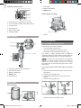
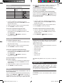
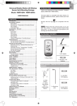
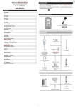
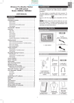
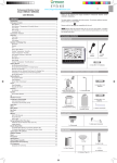
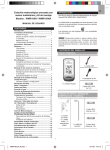
EN
Advanced Weather Station
with Wireless Sensor Set
& Mounting Package
Model: WMR100 / WMR100A
INTRODUCTION
Thank you for selecting the Oregon ScientificTM Weather
Station (WMR100 / WMR100A).
The base station is compatible with other sensors. To
purchase additional sensors, please contact your local
retailer.
USER MANUAL
CONTENTS
Sensors with this logo
unit.
Introduction ................................................................ 1
Packing Contents ....................................................... 1
are compatible with this
NOTE Please keep this manual handy as you use
your new product. It contains practical step-by-step
instructions, as well as technical specifications and
warnings you should know about.
Wind Sensor ................................................................ 1
Rain Gauge .................................................................. 2
Overview ..................................................................... 2
LCD Display ................................................................. 3
PACKAGING CONTENTS
Wind Sensor ................................................................ 4
Rain Gauge .................................................................. 4
Getting Started ........................................................... 4
Set up Remote Wind Sensor ....................................... 4
Set up Remote Rain Gauge ......................................... 6
Set up Base Station ..................................................... 7
Base Station ............................................................... 7
Change Display / Setting ............................................. 7
1 x USB
Cable
Clock Reception ......................................................... 7
1 x 6V
Adapter
Clock / Calendar ......................................................... 8
Clock Alarm ................................................................ 8
4 x UM-3 / AA
Moon Phase ................................................................ 8
Auto Scanning Function ........................................... 8
The “Virtual Weather Station” software and manual are
available for download at this address:
Weather Forecast ....................................................... 8
Temperature and Humidity ....................................... 9
http://www2.oregonscientific.com/assets/software/
wmr100.exe
Temperature and Humidity Trend ................................ 9
Comfort Level ............................................................... 9
Wind Direction / Speed ............................................ 10
WIND SENSOR
UVI / Barometer / Rainfall ........................................ 10
UV Index .................................................................... 11
Barometer .................................................................. 11
Rainfall ....................................................................... 11
Weather Alarms ........................................................ 11
Connection to PC ..................................................... 11
1 x Wind
Vane
Backlight ................................................................... 12
Reset ......................................................................... 12
Accessories – Sensors ............................................ 12
Troubleshooting ....................................................... 12
1 x Top
Pole
Precautions .............................................................. 12
Specifications ........................................................... 13
About Oregon Scientific .......................................... 14
1 x Wind
Sensor
with
“TShaped”
Connector
Eu-declaration of Conformity ................................. 14
FCC Statement ......................................................... 14
Declaration of Conformity .......................................... 14
1 x Wind Direction
Indicator
1
WMR100_EN_86L4515-017.indd 1
6/15/06 4:24:00 PM
EN
OVERVIEW
2 x Rectangular
Base Legs
2 x Round
U-Shaped
Bolts
3 x Pins
3 x Tension Strings
1x
MidPole
1
2
4
3
5
1. MEMORY /
ON/OFF: Read the max
/ min memory record; activate / deactivate alarms
1x
Bottom
Pole
2. ALARM: View and set alarms for barometer,
temperature, humidity, rainfall and wind speed
3. MODE: Switch between the different display modes /
settings
4. Rotating dial: Rotate left or right to increase or
decrease the values of the selected reading
4 x Screws
(Type A)
2 x Screws
(Type B)
5. SELECT: Switch between the different areas
1
2
4 x UM-3
/ AA
1 x Cone-Shaped
End
1 x Plastic
Support Base
3
7
4
5
6
RAIN GAUGE
1. AC adapter socket
2. RESET: Returns unit to default settings
3. SEARCH: Searches for sensors or for the radiocontrolled clock signal
4. UNIT: Selects unit of measurement
1 x Rain
Collector
1 x Filter
5. Battery compartment
2 x UM-3 / AA
6. WMR100 only – EU / UK radio signal
7. USB connector
4 x Screws
(Type C)
6 x Washers
2
WMR100_EN_86L4515-017.indd 2
6/15/06 4:24:24 PM
EN
Wind Speed / Wind Direction Area
LCD DISPLAY
6
1
6
2
3
7
7
1
2
4
5
8
1. Wind speed levels: AVERAGE / MAX / GUST
2. Wind speed level indicator
3
3. Outdoor wind sensor battery is low
4. Wind speed level description
5. Gust wind or wind speed reading (m / s, kph, mph
or knots)
4
6. HI gust wind alarm is set
7. Wind direction display
5
UVI / Barometer / Rainfall Area
1. Weather Forecast Area
2. Temperature / Heat Index / Wind Chill Area
1
3. Wind Speed / Wind Direction Area
2
4. UVI / Barometer / Rainfall Area
7
8
9
3
4
5
5. Clock / Alarm / Calendar / Moon Phase Area
6. AC adapter icon - displays when unplugged
7. Low battery icon for base station
10
6
8. Humidity / Dew Point Area
1. UVI / barometer / rainfall readings is showing
2. Outdoor UV / rain sensor battery is low
Temperature / Heat Index / Wind Chill Area
1
2
3
4
5
3. UV / barometer / rainfall alarm is set
6
7
8
9
7. Accumulated rainfall is showing
4. Rain rate is showing
5. UVI / barometric pressure (mmHg, inHg or mb /
hPa) / rainfall readings (in / hr or mm / hr)
6. UVI level indicator
8. Past 24hrs rainfall is showing
9. Altitude is showing
10. UVI / barometric pressure / rainfall historical bar
chart display
1. Temperature trend
2. Wind Chill level - temperature is showing
Clock / Alarm / Calendar / Moon Phase Area
3. Heat Index level - temperature is showing
1
2
4. HI / LO temperature, HI Heat Index and LO Wind
Chill alarms are set
5. Selected area icon
3
6. Indoor / Outdoor channel temperature and humidity
is displayed
4
5
6
7. MAX / MIN temperature
1. Clock radio reception
8. Outdoor sensor battery is low
2. Alarm 1 and 2 are displayed and set
9. Temperature (°C / °F)
3. Timestamp is displayed
4. Offset time zone
5. Moon phase
6. Time / date / calendar
3
WMR100_EN_86L4515-017.indd 3
6/15/06 4:24:43 PM
EN
Humidity / Dew Point Area
1. Rain gauge
1
2
2. Battery compartment
3. RESET button
3
4
Tipping bucket rain gauge
5
6
1
1. Dew point level - Temperature is showing
2. HI / LO humidity and Dew Point alarms are set
3. Comfort levels
4. Humidity trend
5. MAX / MIN humidity
2
6. Humidity reading
1. Funnel
WIND SENSOR
2. Level indicator
GETTING STARTED
1
2
SET UP REMOTE WIND SENSOR
5
The wind sensor can take 3 readings:
6
•
The wind speed and directions
•
The outdoor temperature (Channel 1 only)
•
The outdoor relative humidity (Channel 1 only)
The sensor is battery operated and is capable of
transmitting data to the base station wirelessly within an
approximate operating range of 100 meters (328 feet).
3
NOTE For best results, ensure that the wind direction
indicator on the wind sensor points to the North to
enable an accurate reading. The sensor also should
be positioned in an open area away from trees or other
obstructions.
4
To set up the wind sensor main body on the steel
pole:
1. Wind vane measuring the wind speed
3. Battery compartment
1. Assemble the wind direction pointer on the top of the
wind sensor.
4. RESET hole
2. Use the screw (Type B) to fix.
5. North indicator
3. Assemble the wind vanes on the top of the wind
pointer.
2. Wind direction sensor
6. Plastic sleeve protecting the batteries
4. Use the screw (Type B) to fix.
RAIN GAUGE
1
Base and funnel
1
2
4
3
2
3
5. Hold the wind sensor upright and rotate the
protective sleeve to the left to unlock.
4
WMR100_EN_86L4515-017.indd 4
6/15/06 4:24:53 PM
10. Assemble the top pole to the mid-pole.
11. Use the screw to fix.
7. Insert batteries (4 x UM-3 / AA) in the compartment,
matching the polarity (+ / -) and press RESET.
8
8. Slide the protective sleeve up to close the
compartment.
10
9
9. Rotate the sleeve to the right to lock.
5
11
7
8
6
EN
6. Slide the sleeve down to open the battery
compartment.
12. Assemble the wind sensor main body on top of the
pole. Use the screw (Type A) to fix.
9
13. Open the battery compartment.
14. Using a compass, rotate the wind direction part until
the NORTH indicator points to the “North”.
15. Press RESET.
To set up the steel pole support:
16. Close the battery compartment.
1. Assemble the “cone shape” guiding end with the
bottom steel pole.
2. Screw the guiding end clockwise at the bottom of
the pole.
13
14
3. Remove the cover hole from the plastic base.
15
12
16
1
17. Insert the 2 rectangular base legs into the ground to
firmly fix the pole.
3
18. To keep the pole stable, use the 3 pins to firmly fix
the tension strings to the ground.
2
4. Insert the plastic base onto the steel pole until the
screw hole aligns with the support.
5. Use the screw that is already attached on the base,
with the washers and bolts to fix.
17
6. Use the guiding end to start inserting the steel pole
at a perpendicular angle into the ground.
18
WARNING Make sure that there are NO electric
cables / power lines, gas / water pipes in the area
where you are placing the steel pole. Do not place
the pole into a hard rocky type of ground as it may
bend or break the pole. It should be inserted into
soft soil.
7. Place a wooden block on the top of the pole. With
a hammer, hit the wooden block to insert the pole at
a perpendicular angle to the ground until reaching
the base.
7
To set up the wind sensor main body on an existing
pole:
5
4
1. Remove the screw that fixes the plastic connector
at the end of the top pole.
6
2. Slide down the plastic connector.
3. Detach plastic base from the bundled steel pole if
previously installed.
8. Assemble the mid-pole on top of the bottom pole.
9. Use the screw to fix.
WMR100_EN_86L4515-017.indd 5
5
4. Assemble it at the end of the top pole using the
screw that is already attached on the base, with the
washers and bolts to fix.
6/15/06 4:25:13 PM
EN
The rain gauge should be mounted horizontally about 1
meter (2-3 feet) from the ground in an open area away
from trees or other obstructions to allow rain to fall
naturally for an accurate reading.
4
1
3
2
To set up the sensor:
1. Slide the cover up and insert the batteries (2 x UM3 / AA), matching the polarity (+ / -).
5. Mount the plastic base on an existing pole.
6. Using the 2 U-bolts, secure the base on the pole
using the 4 washers and bolts.
7. Assemble the wind sensor main body horizontally to
the pole.
8. Use the screw to fix.
9. Open the battery compartment.
6
9
2. Remove the tape.
5
7
8
10. Using a compass, rotate the wind direction part until
the NORTH indicator points to the “North”.
3. Put a few drops of water on the cross at the base of
the funnel to check the horizontal level.
11. Press RESET.
12. Close the battery compartment.
13. Rotate the sleeve to the right to lock.
1
3
10
2
4
12
11
If water remains on 1-4, the gauge is not horizontal.
13
4. If necessary, adjust the level using the screw.
9
7
NOTE For best results, ensure the base is horizontal to
allow maximum drainage of any collected rain.
SET UP REMOTE RAIN GAUGE
The rain gauge collects rain and takes readings of
the total rainfall over a period of time. The sensor can
remotely transmit data to the base station.
The base station and rain gauge should be positioned
within effective range: about 100 meters (328 feet) in an
open area.
6
WMR100_EN_86L4515-017.indd 6
6/15/06 4:25:43 PM
NOTE Install batteries in the remote sensor before the
base station matching the polarities (+ and -).
EN
In addition, the UNIT
and SEARCH buttons
located at the bottom of
the base station allows
pre-setting of the remote
sensor channels and the
measurement units for
display.
SET UP BASE STATION
TIP To exit from the setting mode, push any button.
Alternatively, the base station will automatically exit after
30 seconds.
For continuous use, please install the AC adapter. The
batteries are for back-up use only.
CLOCK RECEPTION
NOTE Please make sure the socket-outlet is installed
near the equipment and is easily accessible.
This product is designed to synchronize its calendar
clock automatically once it is brought within range of a
radio signal:
WMR100:
•
DCF-77 generated from Frankfurt, Germany for
Central Europe
•
MSF-60 generated from Rugby, England
The radio signal range is 1500 km (932 miles).
WMR100A:
•
Install the base station batteries (4 x UM-3 / AA)
matching the polarity + and -. Press RESET after each
battery change.
The radio signal range is 3219 km (2000 miles).
WMR100 only - slide the EU / UK switch to the appropriate
setting based on your location. Press RESET whenever
you change the selected setting.
NOTE Do not use rechargeable batteries. It is
recommended that you use alkaline batteries with this
product for longer performance.
The battery icon indicator
following areas:
The reception icon will blink when it is searching for a
signal. If the radio signal is weak it can take up to 24
hours to get a valid signal reception.
may appear in the
AREA
MEANING
Weather Forecast
Area
Battery in the base station is low.
indicates the status of the clock reception signal.
ICON
will show when AC adapter is
The displayed channel indicates
the outdoor sensor for which
battery is low.
Wind Speed / Wind
Direction Area
Battery in the wind sensor is low.
UVI / Barometer /
Rainfall Area
Battery in the UV / Rain sensor
is low.
MEANING
Time is synchronized.
disconnected.
Temperature / Heat
Index / Wind Chill
Area
WWVB-60 generated from the atomic clock in Fort
Collins, Colorado
Receiving signal is strong
Time is not synchronized.
Receiving signal is weak
To enable (and force a signal search) / disable the
clock radio reception (clock synchronization):
1. Press SELECT to navigate to the Clock / Calendar /
Alarm Area.
will show next to the Area.
2. Press and hold SEARCH.
appears when it is enabled.
NOTE For best reception, the base station should be
placed on a flat, non-metallic surface near a window
in an upper floor of your home. The antenna should
be placed away from electrical appliances and not be
moved around when searching for a signal.
BASE STATION
CHANGE DISPLAY / SETTING
To change the display and settings, use the following
buttons on the rotating dial: SELECT, MEMORY /
ON/OFF, MODE and ALARM.
7
WMR100_EN_86L4515-017.indd 7
6/15/06 4:26:07 PM
EN
To activate / deactivate an alarm:
CLOCK / CALENDAR
1. Press SELECT to navigate to the Clock Area.
will show next to the Area.
To manually set the clock:
(You only need to set the clock and calendar if you have
disabled the clock radio reception.)
2. Press ALARM to toggle between alarm 1
alarm 2
1. Press SELECT to navigate to the Clock Area.
will show next to the Area.
3. Press MEMORY /
deactivate the alarm.
alarm is activated.
2. Press and hold MODE to change the clock setting.
The setting will blink.
3. Rotate the dial left or right to decrease or increase
the setting value.
The Calendar must be set for this feature to work (see
Clock / Calendar section).
5. Repeat steps 1 to 5 to set the time zone offset
hour (+ / -23 hours), 12 / 24 hour format, hour,
minute, year, date / month format, month, date and
weekday language.
ICON
DESCRIPTION
New moon
NOTE If you enter +1 in the time zone setting, this will
give you your regional time plus 1 hour.
Waxing crescent
NOTE The weekday is available in English, French,
German, Italian or Spanish.
First quarter
To change the clock display:
Full moon
1. Press SELECT to navigate to the Clock Area.
will show next to the Area.
Waning gibbous
Waxing gibbous
2. Press MODE to toggle between:
Clock with Seconds
•
Clock with Weekday
•
Calendar
Third quarter
Waning crescent
AUTO SCANNING FUNCTION
CLOCK ALARM
To activate the outdoor temperature and humidity
auto-scan function:
The clock has 2 alarms that can be set to sound with
a beep.
ICON
1. Press SELECT to navigate to the Temperature or
Humidity Area.
will show next to the Area.
MEANING
Alarm 1 or 2 is activated
2. Press and hold MODE to activate auto-scan. The
temperature and humidity display will scroll from
indoor to ch1 through to ch10.
No alarm is set
3. Press MEMORY /
ON/OFF or MODE or
ALARM to stop the auto-scan.
Alarm 1 or 2 is displayed
No icons
to activate or
appears when the
MOON PHASE
4. Press MODE to confirm.
•
and
NOTE Channel 1 is used for the outdoor temperature
and humidity sensor in the remote wind sensor.
Additional temperature and humidity sensors can use
other channels.
To set an alarm:
1. Press SELECT to navigate to the Clock Area.
will show next to the Area.
2. Press ALARM to toggle between alarm 1
alarm 2
display.
WEATHER FORECAST
3. When you’ve selected the alarm you wish to
change, press and hold ALARM. The alarm setting
will blink.
The weather display in the top part of the screen shows
the current weather and the weather forecast for the next
12-24 hours within a 30-50 km (19-31 mile) radius.
4. Rotate the dial left or right to change the setting.
Weather Forecast Area
5. Press ALARM to confirm.
ICON
DESCRIPTION
Sunny
Partly cloudy
8
WMR100_EN_86L4515-017.indd 8
6/15/06 4:26:18 PM
DESCRIPTION
Cloudy
•
Current / MAX heat index
•
Current / MIN wind chill
•
Current / MAX / MIN dew point
•
Current / MAX / MIN humidity
EN
ICON
The timestamp is displayed accordingly in the Clock
Area.
Rainy
To clear the memories and timestamp for the
temperature, heat index, wind chill, humidity and
dew point readings:
Snowy
In the Temperature or Humidity Area, press and hold
MEMORY /
ON/OFF to clear the readings.
TEMPERATURE AND HUMIDITY
The weather station displays indoor and outdoor
readings for:
To change the high / low temperature, heat index,
wind chill, humidity and dew point alarms:
1. Current, minimum and maximum temperatures and
relative humidity.
1. In the Temperature or Humidity Area, press
ALARM repeatedly to toggle between high / low
alarms for temperature, heat index, wind chill,
humidity and dew point readings.
2. Comfort level indicator and trend line.
3. Heat index, wind chill and dew point level.
The weather station can connect up to 10 remote
sensors.
2. Press and hold ALARM to enter the alarm setting.
NOTE Channel 1 is dedicated for outdoor temperature
and humidity in the wind sensor.
4. Press ALARM to confirm the setting.
3. Rotate the dial left or right to set the desired values.
To activate / deactivate the high / low temperature,
heat index, wind chill, humidity and dew point
alarms:
shows which remote sensor’s data you are viewing.
appears when indoor data is displayed.
The timestamp records the date and time when storing
the temperature and humidity readings in memory.
1. In the Temperature or Humidity Area, press ALARM
repeatedly to select the desired alarm.
To select the temperature measurement unit:
2. Press MEMORY /
ON/OFF to activate or
deactivate the alarm.
Press UNIT (at the bottom of the base station) to select
°C / °F.
NOTE The dew point advises at what temperature
condensation will form. The wind chill factor is based on
the combined effects of temperature and wind speed.
NOTE The unit of all temperature related displays will
be changed simultaneously.
TEMPERATURE AND HUMIDITY TREND
To view readings from indoor / outdoor sensors
(1-10) for temperature and humidity:
The trend lines are shown next to the temperature and
humidity readings. The trend is shown as follows:
1. Press SELECT to navigate select the Temperature
or Humidity Area.
will show next to the Area.
TREND ICON
2. Rotate the dial left or right to select the channel.
DESCRIPTION
Rising
Steady
To view minimum and maximum temperature or
humidity:
Falling
1. In the Temperature or Humidity Area, press MODE
repeatedly to cycle through the readings for:
•
Current Temperature
COMFORT LEVEL
•
Heat Index
•
Wind Chill
•
Dew Point
The Comfort Zone icon indicates how comfortable the
climate is based on current temperature and humidity
measurements:
•
Humidity
ICON
2. Forr each of the above readings, press MEMORY /
ON/OFF repeatedly to toggle respectively
between:
•
DESCRIPTION
Comfortable
Neutral
Uncomfortable
Current / MAX / MIN temperature
9
WMR100_EN_86L4515-017.indd 9
6/15/06 4:26:22 PM
EN
To activate / deactivate the high gust wind speed
alarm:
WIND DIRECTION / SPEED
The base station provides
wind speed and wind
direction information.
1. In the Wind Speed and Wind Direction Area, press
ALARM repeatedly to select the desired alarm.
2. Press MEMORY /
ON/OFF to activate or
deactivate the alarm.
To read the wind direction
find the compass point the
is pointing to.
UVI / BAROMETER / RAINFALL
The timestamp records the date and time when storing
the wind speed readings.
The weather station works with one UV sensor and
one rain gauge. The station is capable of storing and
displaying the hourly history data for the last 10 hours
of UV index, and 24 hours of rainfall and barometric
pressure readings.
To select the wind speed unit:
Press UNIT (at the bottom of the base station) to switch
between:
•
Metres per second (m / s)
•
Kilometers per hour (kph)
•
Miles per hour (mph)
•
Knots (knots)
UVI
BAROMETER
RAINFALL
The wind level is shown by a series of icons:
ICON
LEVEL
DESCRIPTION
N/A
<2 mph (<4km/h)
Light
2-8 mph (3~13 km/h)
Moderate
9-25 mph (~14-41 km/h)
To view the UV / Barometer / Rainfall readings:
Strong
26-54 mph (~42-87 km/h)
1. Press SELECT to navigate to the UV / Barometer /
Rainfall Area.
will show next to the Area.
Storm
>55 mph (>88 km/h)
The bar chart display shows the current and historical
data for the UV index, barometric pressure and rainfall
readings.
2. Press MODE to toggle between UVI / Barometer
/ Rainfall readings. The corresponding icon will
appear:
To display the AVERAGE and GUST wind:
UVI
1. Press SELECT to navigate to the Wind Speed and
Wind Direction Area.
will show next to the Area.
BAROMETER
RAINFALL
2. Press MODE to toggle between AVERAGE and
GUST wind readings.
3. Rotate the dial left or right to view the historical data
for the selected area. The corresponding historical
readings are showing.
To display the maximum speed and direction for
gust wind:
In the Wind Speed and Wind Direction Area, press
MEMORY /
ON/OFF to toggle between wind speed
/ MAX GUST wind readings. The timestamp is displayed
accordingly in the Clock Area.
NOTE The number shown in the HR icon indicates how
long ago each measurement was taken (e.g. 2 hours
ago, 3 hours ago, etc.).
To clear the memories and timestamp for the wind
readings:
To select the measurement unit for the barometer or
rainfall readings:
In the Wind Speed and Wind Direction Area, press and
hold MEMORY /
ON/OFF to clear the readings.
In the UV / Barometer / Rainfall Area, press UNIT (at the
bottom of the base station) to switch between:
•
For barometer: Millimeters of mercury (mmHg),
inches of mercury (inHg), millibars per hectopascal
(mb / hpa).
•
For rainfall: Millimeters (mm), inches (in), inches per
hour (in / hr) or millimeters per hour (mm / hr).
To change the high gust wind speed alarm:
1. In the Wind Speed and Wind Direction Area, press
and hold ALARM to enter the high gust wind alarm
setting.
2. Rotate the dial left or right to set the desired values.
3. Press ALARM to confirm the settings.
10
WMR100_EN_86L4515-017.indd 10
6/15/06 4:26:27 PM
The UV index levels are as follows:
To toggle between rainfall & rain rate display:
UV INDEX
DANGER
LEVEL
0-2
Low
To reset the accumulated rainfall and timestamp:
3-5
Moderate
6-7
High
In the UV / Barometer / Rainfall Area and Rainfall reading
display. Press and hold MEMORY /
ON/OFF to reset
the accumulated rainfall to ‘0’ and to set the timestamp
to current date and time.
8-10
Very high
11 and above
Extremely high
EN
time when the accumulated rainfall is displayed. The
icon
appears and the start date is showing.
UV INDEX
ICON
In the UV / Barometer / Rainfall Area and Rainfall reading
display, press and hold MODE.
To change the HI rainfall rate alarm:
To change the high UV alarm:
1. In the UV / Barometer / Rainfall Area and Rainfall
reading display, press and hold ALARM to enter the
Rainfall alarm setting.
1. In the UV / Barometer / Rainfall Area and UVI
reading display. Press and hold ALARM to enter the
high UV alarm setting.
2. Rotate the dial left or right to set the desired values.
2. Rotate the dial left or right to set the desired values.
3. Press ALARM to confirm the settings.
3. Press ALARM to confirm the settings.
To activate / deactivate the high UV alarm:
To activate / deactivate the HI rainfall rate alarm:
1. In the UV / Barometer / Rainfall Area and UVI
reading display, press ALARM repeatedly to select
the desired alarm.
1. In the UV / Barometer / Rainfall Area and Rainfall
reading display, press ALARM repeatedly to select
the desired alarm.
2. Press MEMORY /
ON/OFF to activate or
deactivate the alarm.
2. Press MEMORY /
ON/OFF to activate or
deactivate the alarm.
BAROMETER
WEATHER ALARMS
To change the barometer alarm:
Weather alarms are used to alert you of certain weather
conditions. Once activated, the alarm will go off when a
certain criterion is met.
1. In the UV / Barometer / Rainfall Area and Barometer
reading display. press and hold ALARM to enter the
Barometer alarm setting.
Alarms can be set for:
2. Rotate the dial left or right to set the desired values.
•
Indoor and outdoor high/low temperatures, dew point
and high/low humidity
3. Press ALARM to confirm the settings.
•
High Heat Index
To activate / deactivate the barometer alarm:
•
High Gust Wind
1. In the UV / Barometer / Rainfall Area and Barometer
reading display, press ALARM repeatedly to select
the desired alarm.
•
Low wind chill
•
High UV
•
Pressure drop
•
High rain rate
2. Press MEMORY /
ON/OFF to activate or
deactivate the alarm.
See the relevant section for how to set the alarm.
To set the altitude level compensation for the
Barometer readings:
To silence any alarm: Press any button or rotate the
dial.
1. In the UV / Barometer / Rainfall Area and Barometer
reading display. Press and hold MODE to enter the
altitude setting.
CONNECTION TO PC
2. Rotate the dial left or right to set the desired values.
The weather station is capable of connecting to a PC
computer using the USB connection. The “Virtual
Weather Station” software can read the latest weather
data collected from the base station. Please download
the software from the following website:
3. Press MODE to confirm the setting.
RAINFALL
http://www2.oregonscientific.com/assets/software/
wmr100.exe
To view the current hour, accumulated or last 24
hours rainfall history:
For full details see the “Virtual Weather Station” software
instructions.
In the UV / Barometer / Rainfall Area and Rainfall reading
display, press MEMORY /
ON/OFF repeatedly to
toggle between current, past 24 hours or accumulated
rainfall. The clock line will change to display the start
11
WMR100_EN_86L4515-017.indd 11
6/15/06 4:26:29 PM
EN
PC System requirements
PROBLEM
SYMPTOM
REMEDY
The minimum system requirements for use of the “Virtual
Weather Station” software is:
Temp
Shows “LLL” or
“HHH”
Temperature is
out-of-range
•
Operating system: Microsoft Windows 98 or above
•
Processor: Pentium II 166Mhz or above
Remote
sensor
Cannot locate
remote sensor
1. Check
batteries
2. Check if
sensors are
within range
• RAM: Min. 64Mb
•
Hard disk free space: Min. 30Mb
To connect the base station to the computer:
PRECAUTIONS
3
2
This unit is engineered to give you years of
satisfactory service if you handle it carefully. Here are
a few precautions:
• Placement of this product on wood surfaces with
certain types of finishes, such as clear varnish, may
result in damage to the finish. Consult the furniture
manufacturer’s care instructions for direction as to
the types of objects that may safely be placed on
the wood surface. Oregon Scientific shall not be
responsible for any damage to wood surfaces from
contact with this product.
• Do not cover the ventilation holes. Make sure
items that are nearby such as newspapers,
tablecloths, curtains etc cannot accidentally cover
the ventilation holes.
• Do not immerse the unit in water. If you spill liquid
over it, dry it immediately with a soft, lint-free cloth.
• Do not clean the unit with abrasive or corrosive
materials. This may scratch the plastic parts and
corrode the electronic circuit.
• Do not subject the unit to excessive force, shock,
dust, temperature or humidity, which may result in
malfunction, shorter electronic life span, damaged
battery and distorted parts.
• This product may malfunction if electrostatic
discharge or radio interference appears in the
environment and / or affects the ac power line. The
unit will revert to normal operation when interference
stops.
• Do not tamper with the unit’s internal components.
Doing so will invalidate the warranty on the unit and
may cause unnecessary damage. The unit contains
no user-serviceable parts.
• Only use fresh batteries as specified in the user’s
instructions. Do not mix new and old batteries as the
old ones may leak.
• Do not dispose this product as unsorted municipal
waste. Collection of such waste separately for special
treatment is necessary.
• Due to printing limitations, the displays shown in this
manual may differ from the actual display.
• The contents of this manual may not be reproduced
without the permission of the manufacturer.
1
1. Uncover the USB point on the side of the
base station.
2. Plug in the USB cable.
3. Plug in the other end of the cable in the computer.
BACKLIGHT
Press any button or rotate the dial to activate the
backlight.
RESET
Press RESET to return to the default settings.
ACCESSORIES – SENSORS
This product can work with up to 10 sensors at any one
time to capture outdoor temperature, relative humidity
or UV readings in various locations. Optional wireless
remote sensors such as those listed below can be
purchased separately. For more information, please
contact your local retailer.
•
Thermo-hygro THGR800 (3-Ch)
•
Thermo-hygro THGR810 (10-Ch)
•
UV UVN800
TROUBLESHOOTING
PROBLEM
Barometer
SYMPTOM
Strange
readings
REMEDY
Set unit
Calendar
Strange date /
month
Change
language
Clock
Cannot adjust
clock
Disable radiocontrolled clock
Cannot autosynch
1. Adjust
batteries
NOTE The technical specifications for this product and
the contents of the user manual are subject to change
without notice.
2. Press RESET
3. Manually
activate radiocontrolled
clock
12
WMR100_EN_86L4515-017.indd 12
6/15/06 4:26:31 PM
EN
SPECIFICATIONS
REMOTE WIND SENSOR UNIT
BASE STATION
Weight
556 g (1.23 lbs) without battery
Wind speed unit
m/s, kph, mph, knots
Speed accuracy
2 m/s ~ 10 m/s (+/- 3 m/s)
10 m/s ~ 56 m/s (+/- 10%)
Direction accuracy
16 positions
Transmission of
wind speed signal
Approx. every 14 seconds
Memory
Max speed gust
Dimensions
(L x W x H)
143 x 89 x 165 mm
(5.6 x 3.5 x 6.5 inches)
Weight
300g (0.66 lbs) without battery
INDOOR BAROMETER
Barometer unit
mb/hPa, inHg and mmHg
Measuring range
700 – 1050mb/hPa
Accuracy
+/- 10 mb/hPa
OUTDOOR TEMPERATURE
Resolution
1mb (0.0 inHg)
Temp. unit
°C / °F
Altitude setting
Sea level
User setting for compensation
Displayed range.
-50°C to 70°C (-58°F to 158°F)
Weather display
Sunny, Partly Cloudy, Cloudy,
Rainy and Snowy
Operating range.
-30°C to 60°C (-4°F to 140°F)
Accuracy
Memory
Historical data and bar chart for
last 24hrs
-20°C – 0°C: +/- 2°C (+/- 4.0°F)
0°C - 40°C: +/- 1°C (+/- 2.0°F)
40°C - 50°C: +/- 2°C (+/- 4.0°F)
50°C - 60°C: +/- 3°C (+/- 6.0°F)
INDOOR TEMPERATURE
Comfort
20°C to 25°C (68°F to 77°F)
Memory
Current, min and max temp.
Dew Point w/ max and min
Wind chill temp. and min
Temp. unit
°C / °F
Displayed range.
0°C to 50°C (32°F to 122°F)
Operating range.
-30°C to 60°C (-4°F to 140°F)
Accuracy
0°C - 40°C: +/- 1°C (+/- 2.0°F)
40°C - 50°C: +/- 2°C (+/- 4.0°F)
Comfort
20°C to 25°C (68°F to 77°F)
Operating range.
25% to 90%
Memory
Current, min and max temp.
Dew Point w/ min and max
Resolution
1%
Accuracy
Alarm
Hi / Lo
25% - 40%: +/- 7%
40% - 80%: +/- 5%
80% - 90%: +/- 7%
RELATIVE HUMIDITY
Displayed range.
2% to 98%
INDOOR RELATIVE HUMIDITY
Comfort
40% to 70%
Displayed range
2% to 98%
Memory
Current, min and max
Operating range
25% to 90%
Resolution
1%
Accuracy
25% - 40%: +/- 7%
40% - 80%: +/- 5%
80% - 90%: +/- 7%
Comfort
RF TRANSMISSION
RF frequency
433MHz
Range
Up to 100 meters (328 feet) with
no obstructions
40% to 70%
Transmission
Approx. every 60 seconds
Memory
Current, min and max
No. of Channel
Alarm
Hi / Lo
1 for Wind/ Rain/ UV and 10 for
Temp. / Humidity
Battery
4 x UM-3 (AA) 1.5V
RADIO-CONTROLLED / ATOMIC CLOCK
Synchronization
Auto or disabled
Clock display
HH:MM:SS
Hour format
12hr AM/PM or24hr
Calendar
DD/MM or MM/DD
Weekday in 5
languages
(E, G, F, I, S)
Battery
4 x UM-3 (AA) 1.5V batteries
AC adapter
6V
REMOTE RAIN GAUGE
Dimensions
(L x W x H)
107 x 87 x 56 mm
(4.2 x 3.4 x 2.2 inches)
Weight
134 g (0.3 lbs) without battery
Rainfall unit
Mm/hr and in/hr
Range
0 mm/hr – 999 mm/hr
Resolution
1 mm/hr
Accuracy
< 15 mm/hr: +/- 1 mm
15 mm to 9999 mm: +/- 7%
Memory
Past 24hrs, hourly and accumulated
from last memory reset
Battery
2 x UM-3 (AA) 1.5V
13
WMR100_EN_86L4515-017.indd 13
6/15/06 4:26:33 PM
EN
particular installation. If this equipment does cause
harmful interference to radio or television reception,
which can be determined by turning the equipment
off and on, the user is encouraged to try to correct the
interference by one or more of the following measures:
ABOUT OREGON SCIENTIFIC
Visit our website (www.oregonscientifi
www.oregonscientific.com)
c.com to learn
more about Oregon Scientific products such as digital
cameras; MP3 players; children’s electronic learning
products and games; projection clocks; health and
fitness gear; weather stations; and digital and conference
phones. The website also includes contact information
for our Customer Care department in case you need
to reach us, as well as frequently asked questions and
customer downloads.
We hope you will find all the information you need on our
website, however if you’re in the US and would like to
contact the Oregon Scientific Customer Care department
directly, please visit:
•
Reorient or relocate the receiving antenna.
•
Increase the separation between the equipment and
receiver.
•
Connect the equipment into an outlet on a circuit
different from that to which the receiver is connected.
•
Consult the dealer or an experienced radio / TV
technician for help.
DECLARATION OF CONFORMITY
www2.oregonscientific.com/service/default.asp
The following information is not to be used as contact
for support or sales. Please call our customer service
number (listed on our website at www.oregonscientific.
com), or on the warranty card for this product) for all
inquiries instead.
OR
Call 1-800-853-8883.
For international inquiries, please visit:
www2.oregonscientific.com/about/international.asp
We
EU-DECLARATION OF CONFORMITY
Hereby, Oregon Scientific, declares that this Weather
Station with Wireless Rain and Wind sensors model
WMR100 is in compliance with the essential requirements
and other relevant provisions of Directive 1999/5/EC. A
copy of the signed and dated Declaration of Conformity is
available on request via our Oregon Scientific Customer
Service.
Name:
Oregon Scientific, Inc.
Address:
19861 SW 95th Ave., Tualatin,
Oregon 97062 USA
Telephone No.:
1-800-853-8883
declare that the product
COUNTRIES RTTE APPROVAL COMPLIED
All EU countries, Switzerland CH
and Norway N
Product No.:
WMR100A
Product Name:
Professional Weather Station
Manufacturer:
IDT Technology Limited
Address:
Block C, 9/F, Kaiser Estate,
Phase 1,41 Man Yue St.,
Hung Hom, Kowloon,
Hong Kong
is in conformity with Part 15 of the FCC Rules. Operation
is subject to the following two conditions:
FCC STATEMENT
This device complies with Part 15 of the FCC Rules.
Operation is subject to the following two conditions: (1)
This device may not cause harmful interference, and
(2) This device must accept any interference received,
including interference that may cause undesired
operation.
1. This device may not cause harmful interference.
2. This device must accept any interference
received, including interference that may cause
undesired operation.
WARNING Changes or modifications not expressly
approved by the party responsible for compliance could
void the user’s authority to operate the equipment.
NOTE This equipment has been tested and found
to comply with the limits for a Class B digital device,
pursuant to Part 15 of the FCC Rules. These limits
are designed to provide reasonable protection against
harmful interference in a residential installation.
This equipment generates, uses and can radiate radio
frequency energy and, if not installed and used in
accordance with the instructions, may cause harmful
interference to radio communications. However, there
is no guarantee that interference will not occur in a
WMR100_EN_86L4515-017.indd 14
14
6/15/06 4:26:34 PM
EN
Advanced Weather Station
with Wireless Sensor Set
& Mounting Package
Model: WMR100 / WMR100A
USER MANUAL
15
WMR100_EN_86L4515-017.indd 15
6/15/06 4:26:34 PM
EN
© 2006 Oregon Scientific. All rights reserved.
086L004515-017
16
WMR100_EN_86L4515-017.indd 16
6/15/06 4:26:35 PM